equivalent circuit model to characterize the coplanar waveguide structure, which consists of relatively thick metal line on very thick polyimide over lossy substrate ...
856
IEEE TRANSACTIONS ON ELECTRON DEVICES, VOL. 44, NO. 5, MAY 1997
Simple Modeling of Coplanar Waveguide on Thick Dielectric over Lossy Substrate Jin-Su Ko, Bon-Kee Kim, and Kwyro Lee, Senior Member, IEEE
Abstract—We present a simple semi-empirical high-frequency equivalent circuit model to characterize the coplanar waveguide structure, which consists of relatively thick metal line on very thick polyimide over lossy substrate such as Si BiCMOS wafer. Considering the geometric dependence of the conductive loss and the skin effect of the substrate loss, we derive modified models for the equivalent circuit elements. We verify the validity of our model by comparing it with the experimental measurement. Our model is simple enough not only to be suitable for efficient circuit simulation but also to be useful for process characterization and design.
I. INTRODUCTION
T
HERE IS A strong interest in the monolithic integration of radio frequency (RF) and microwave circuits for the growing market of wireless communications. It is very desirable to integrate both the active and the passive devices on a silicon wafer because it is a very mature technology and it allows much higher integration density. Furthermore, very efficient integration of RF and logic circuits is feasible if BiCMOS technology is used. However, the use of standard silicon technology has serious drawback of various RF losses due to the lossy substrate and the limited metal thickness [1]. Recently, many attempts to remedy this have been proposed especially for the monolithic inductors [2]–[5]. Among these, interconnection technology based on thick polyimide/thick metal [3] seems to be most promising since it gives very high performance without adding too much process complexity. It should be noted here that the process technology for the high-performance inductor is almost the same as that for the interconnection. In this paper, we suggest a simple semi-empirical equivalent circuit model to characterize the coplanar waveguide structure based on this new process. This model is suitable for the efficient circuit simulation as well as very useful for process characterization and design. In Section II, we describe the fabrication technology and microwave measurement method briefly. This is followed by the equivalent circuit model in Section III. In Section IV, we compare the model developed in Section III with the experimental results obtained as described in Section II and discuss its validity. The implications given Manuscript received October 21, 1996; revised January 7, 1997. The review of this paper was arranged by Editor C.-Y. Lu. J.-S. Ko was with the Department of Electrical Engineering, Korea Advanced Institute of Science and Technology (KAIST), Taejon 305-701, Korea. He is now with Samsung Electronics Company, Kyungki-Do 449-900, Korea. B.-K. Kim and K. Lee are with the Department of Electrical Engineering, Korea Advanced Institute of Science and Technology (KAIST), Taejon 305701, Korea. Publisher Item Identifier S 0018-9383(97)03011-6.
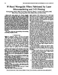
Fig. 1. The schematic cross section of the coplanar waveguide structure studied in this paper.
by the model are also discussed. Finally, some conclusions are drawn in Section V. II. MONOLITHIC COPLANAR WAVEGUIDE FABRICATION BASED ON THICK METAL/POLYIMIDE ON SILICON WAFER Our coplanar waveguide structure fabrication is started from the fully processed double metal BiCMOS wafer. The resistivity of the bulk silicon is about 20 -cm. The doping density and the thickness for the p-type epitaxial layer are cm and m, respectively, resulting in 5.1 sheet resistance. On top of the processed double metal standard BiCMOS wafer, about 10- m thick dielectric (polyimide) and 3.8- m thick metal 3 (aluminum) are deposited and patterned, respectively. The schematic cross section of the coplanar waveguide (CPW) structure using this process is shown in Fig. 1. In this work, three different coplanar waveguide structures are studied. The designed separation for the three coplanar waveguide lines is 10 m, 20 m, and 30 m, respectively. The designed waveguide width is fixed at 20 m, and the longitudinal length is at 1 mm. Note that since metal 3 is etched by wet chemical, the actual metal 3 size on wafer is much smaller than the designed one. The etch bias in our case is about 3 m per side, that is, m and m , where is the actual (design) width and is the actual (design) separation for the CPW. -parameter measurements are performed over the frequency range from 1 GHz to 10 GHz, using on-wafer Cascade Microtech probes and Wiltron 360B Vector Network Analyzer. Measured data are de-embedded using dummy patterns to remove the pad parasitic effects. The basic -parameter sub-
0018–9383/97$10.00 1997 IEEE
KO et al.: SIMPLE MODELING OF COPLANAR WAVEGUIDE
857
Fig. 2. Equivalent circuit model per unit length for the coplanar waveguide studied in this paper.
traction method developed in [6] and [7] is adopted to extract the pure waveguide parameters. From the de-embedded parameters, we calculate the complex characteristic impedance and the complex propagation constant using the method proposed in [7]. From the extracted and , we finally calculate the four circuit elements in the equivalent transmission line model shown in Fig. 2 by the method described in [7]. III. EQUIVALENT CIRCUIT MODEL Hasegawa et al. [8] showed that when the wave propagates in MIS (metal-insulator-semiconductor), the three fundamental modes exist. The characteristic and the condition for the appearance of each mode are clarified as follows [8], [9]. 1) When the product of frequency and the resistivity of the semiconductor substrate is large enough to produce a small dielectric loss tangent, the substrate acts like a dielectric. Both the transverse electric and the magnetic fields and , respectively,) can freely penetrate into the semiconductor substrate and the propagation mode of so-called “dielectric quasi-TEM mode” occurs. 2) When the product of frequency and substrate conductivity is large enough to yield the small penetration depth into the substrate, the substrate behaves like a lossy conductor wall. In this case, the propagation mode is called as “skin-effect mode,” where neither nor penetrates into the semiconductor substrate. 3) When the frequency is low compared with the dielectric relaxation frequency, , given by
guide structure. Using worst case parameters for the three transmission lines under consideration, the dielectric relaxation frequency and the skin depth are 177 GHz and 469 m, respectively, for the epitaxial layer and and are 7.7 GHz and 2250 m, respectively, for the bulk substrate. Note first that both ’s are much larger than the quasi-static field range (the largest one is m m in our CPW. Because the electromagnetic fields in our CPW are localized nearly at silicon surface, we conservatively estimate the effective to be larger than 10 GHz. Therefore, we can treat the propagation mode of our structure as slowwave mode. Kwon et al. [9] showed that the slow-wave mode propagation on coplanar MIS structure is a quasi-TEM mode and can therefore be treated by fairly elementary techniques. Using the above assumptions, we suggest a modified simple equivalent circuit and modified element models to represent the coplanar waveguide structures studied in this paper as shown in Fig. 2. Metal conductive losses are introduced as in series with longitudinal inductance and energy storage and loss associated with the transverse electric field and the transverse current are represented by the dielectric capacitance and substrate resistance , respectively. Since the magnetic field profile of the present structure is nearly the same as that in the normal coplanar waveguide, can be determined by conformal mapping. This leads to [9], [11] (3) Here, is velocity of light and can be approximated by [11]
for (4) for
Here,
(1) and when the depth of quasi-static field penetration into the substrate is small compared with the skin depth of the substrate, defined as
is a geometric factor which
(5) and
(2)
(6)
the substrate acts like neither of the above. Here, and are the conductivity and the dielectric constant, respectively, of the substrate. and are the permittivity of free space and the permeability of substrate, respectively. This mode of propagation is called as the “slow-wave mode” and freely penetrates into the does not. semiconductor substrate while The earlier works [9], [10] showed that this quasi-static field range is about in the coplanar wave-
In this paper, we introduce the parameter as the correction factor for the thick metal thickness and its trapezoidal cross section because the above equations assume infinitesimally thin metallic strip conductor and ground planes. For example, the value of is found to be about 1.3 in our case. Since electric field is largely confined to the dielectric layer below the center conductor (note that in slow wave mode, the substrate behaves as the ground plane as far as the electric field is concerned), the dielectric capacitance including fringing
858
IEEE TRANSACTIONS ON ELECTRON DEVICES, VOL. 44, NO. 5, MAY 1997
Fig. 3. Comparison between model (lines) and the experimental measurement (dots) for the frequency dependent four equivalent circuit elements defined in Fig. 2. The values of So =Wo are 20/10 (model: and measurement: ); 20/20 (— — — — and � � � �), and 20/30 (1 1 1 1 1 and 2 2 2 2 ), respectively.
This formula expresses the series skin resistance per unit length in terms of that part of the total inductance per unit length, which is attributable to the skin effect, that is, to the inductance produced by the magnetic field within the metallic conductors. Using this formula, the conductive loss resistance of CPW can be derived as [11]
field effects is approximated by [12]
(7)
where represents the thickness of metal 3 and is the effective thickness of multi-dielectric layers and is calculated by (8) , and are the dielectric constants of where polyimide, PSG, and oxide layer, and , and are the thickness of polyimide, PSG, and oxide layer, respectively. in (3), we introduce the correction factor In (7), similarly to for the trapezoidal cross section as shown in Fig. 1. The value of is found to be 0.79 in our case. The complicated full-wave analysis [13] verified that the capacitance of our trapezoidal shape is smaller than one of rectangular shape. The derivation for the longitudinal conductive loss is usually based upon “Wheeler’s incremental inductance” formula [14].
(9)
where for for (10) Here, represents the sheet resistance of the metal 3 and and are the effective dielectric constant and the characteris defined as and istic impedance, respectively. is used as in this work. and are already defined in (4) and (5).
KO et al.: SIMPLE MODELING OF COPLANAR WAVEGUIDE
859
Fig. 4. Comparison between model (lines) and the experimental measurement (dots) for the characteristic impedance (magnitude and angle), the attenuation, and the slow-wave factor. The values of So =Wo are 20/10 (model: and measurement: ); 20/20 (— — — — and � � � �), and 20/30 (1 1 1 1 1 and 2 2 2 2 ), respectively.
Because Wheeler’s formula is valid only when the metal thickness is larger than the skin depth by at least a factor of four, we cannot use it directly. (Note that the skin depth of metal 3 is 1.9 m at 2 GHz.) Thus, we adopt the effective sheet resistance in (9) as follows [7]: (11) used in [11]. Here, and are the instead of the conductivity and the skin depth, respectively, of the metal 3. To derive the expression for in Fig. 2, note first that for both the epitaxial layer and bulk substrate. Accordingly, transverse current flow is predominantly resistive and can be represented by in series with as shown. should include the skin effects of metal 3 ground lines, too. In this paper, we propose (12) The derivation of term in (12) was based upon the analogy between the transverse resistance of our structure and the inverse transverse capacitance of normal CPW [9]. This skin effect was ignored in [9] because of the heavily doped substrate cm However, since the low doped substrate is widely used in Si MMIC to decrease the substrate loss of passive components, it is important to consider the skin effect loss in modeling.
In this paper, we preclude the longitudinal semiconductor current flows described in [9] because the magnitude of this impedance is very large compared with that of the impedance of and in series, at typically low bulk doping for high-frequency applications. As a result, four circuit and can be compared directly elements with the four circuit elements extracted from four measured -parameters, that is, complex and complex
IV. COMPARISON BETWEEN MEASUREMENT AND MODELING Using (3)–(12), the circuit elements , and are calculated and are compared with the measured values as described in Section II. The results are shown in Fig. 3. the attenuation constant , and The complex the slow-wave factor are also compared in Fig. 4. As can be seen from measured data, series inductance and conductive loss resistance are dependent on the is almost independent of it. The CPW separation, while effective dielectric constant calculated from the slow-wave factor is larger than the dielectric constants of either dielectric layer. From these results, our assumptions that the transverse magnetic field penetrates into the substrate while transverse electric field does not and that the wave propagation of our CPW is slow-wave mode can be justified.
860
IEEE TRANSACTIONS ON ELECTRON DEVICES, VOL. 44, NO. 5, MAY 1997
As can be seen from Fig. 3, metallic loss resistance and substrate resistance are affected by the CPW separation and skin effect, respectively, in agreement with our modified models given by (9) and (12). Moreover, also modeled series inductance and dielectric capacitance show good agreement with measured values as shown in Fig. 3. As a result, the calculated magnitude and angle of show good agreement with measured values as shown in Fig. 4. The attenuation constant of Fig. 4, however, shows a relatively large error (about 15%) especially at high frequency due to the inaccuracy in modeling. (See Fig. 3.) The discrepancy of between measurement and modeling could be originated in the substrate doping fluctuation. The attenuation constant can be approximated by [9]
for
and
(13)
and Here the first term expresses the conductor loss the second one does the substrate loss In Fig. 4, calculated and are plotted together for the case of m We find that the sum of each loss is equal nearly to the total loss and this justifies our assumptions in (13). It is also very interesting to note that is dominant over for GHz and vice versa for GHz. It should be noted, however, that the cross frequency point, where is identical to , varies depending on the CPW geometry. As can be seen in Fig. 4, the attenuation of our CPW is quite small. The maximum observed attenuation of approximately 0.33 dB/mm m m at 10 GHz, is, to the best of our knowledge, considerably less than any other data obtained from standard (several tens -cm) Si substrate. This small loss is due to the thick metal 3 which reduces the conductive loss drastically and the thick polyimide which reduces both the substrate loss and the conductive loss by reducing drastically. (Note that is proportional to and to in (13).) In our metal 3 BiCMOS process, the substrate loss is more dominant than the conductor loss at high frequency due to thick metal as shown in Fig. 4. Therefore, at high frequency, much loss reduction could have been obtained if we used highly n-doped layer such as n buried layer and/or metal 1 and metal 2 underneath the CPW which are always available in BiCMOS technology. This would increase the conductive loss at low frequency due to the reduction in [See (13)]. However, more experiments are needed to clarify these points.
V. CONCLUSION We derive a simple semi-empirical equivalent circuit model for the coplanar waveguide structure which consists of thick metal line on very thick dielectric over low doped Si substrate.
Specially, we take into account the skin effect for the substrate loss and the geometric dependence of CPW for the metallic loss Our model agrees well with the measured values from the s-parameters in the frequency range from 1 GHz to 10 GHz. These results show that our coplanar waveguide not only shows the least loss ever reported from standard (low doped) silicon substrate but also can indeed be characterized by a quasi-TEM mode due to the slow-wave propagation. Our model is simple enough not only to be suitable for efficient circuit simulation but also to be useful for process characterization and design.
ACKNOWLEDGMENT The authors would like to thank the Media Technology Team of Samsung Electronics Company Ltd., Korea, for help in the CPW fabrication process. They also appreciate the reviewers for their valuable comments.
REFERENCES [1] H. Hasegawa and S. Seki, “Analysis of interconnection delay on very high-speed LSI/VLSI chips using an MIS microstrip line model,” IEEE Trans. Microwave Theory Tech., vol. MTT-32, pp. 1721–1727, Dec. 1984. [2] J. Y. -C. Chang, A. A. Abidi, and M. Gaitan, “Large suspended inductors on silicon and their use in a 2-�m CMOS RF amplifier,” IEEE Electron Device Lett., vol. 14, pp. 246–248, May 1993. [3] B. K. Kim, B. K. Ko, K. Lee, J. W. Jeong, K. S. Lee, and S. C. Kim, “Monolithic planar RF inductor and waveguide structures on silicon with performance comparable to those in GaAs MMIC,” in IEDM Tech. Dig., 1995, pp. 717–720. [4] J. N. Burghartz, M. Soyuer, K. A. Jenkins, and M. D. Hulvery, “HighQ inductors in standard silicon interconnection technology and its application to an integrated RF power amplifier,” in IEDM Tech. Dig., 1995, pp. 1015–1017. [5] M. Case, P. MacDonald, M. Matloubian, M. Chen, L. Larson, and D. Rensch, “High-performance microwave elements for SiGe MMIC’s,” in Proc. IEEE/Cornell Conf. Advanced Concepts in High-Speed Semiconductor and Circuits, Aug. 1995, pp. 85–92. [6] P. J. Van Wijen, H. R. Classen, and E. A. Wolsheimer, “A new straightforward calibration and correction procedure for “on wafer” high-frequency S -parameter measurements (45 MHz–18 GHz),” in Proc. IEEE BCTM, 1987, pp. 70–73. [7] Y. Eo, and W. R. Eisenstadt, “High-speed VLSI interconnect modeling based on S -parameter measurements,” IEEE Trans. Comp. Hybrids, Manuf. Technol., vol. 16, pp. 555–562, Aug. 1993. [8] H. Hasegawa, M. Furukawa, and H. Yanai, “Properties of microstrip line on Si-SiO2 system,” IEEE Trans. Microwave Theory Tech., vol. MTT-19, pp. 869–881, Nov. 1971. [9] Y. R. Kwon, V. M. Hietala, and K. S. Champlin, “Quasi-TEM analysis of slow-wave mode propagation on coplanar microstructure MIS transmission lines,” IEEE Trans. Microwave Theory Tech., vol. MTT-35, pp. 545–551, June 1987. [10] M. E. Davis, E. W. Williams, and A. C. Celestini, “Finite-boundary corrections to the coplanar waveguide analysis,” IEEE Trans. Microwave Theory Tech., vol. MTT-21, pp. 594–596, Sept. 1973. [11] K. C. Gupta, R. Garg, and I. J. Bahl, Microstrip Lines and Slotlines. Dedham, MA: Artech House, 1979, ch. 7. [12] C. P. Yuan and T. N. Trick, “A simple formula for the estimate of the capacitance of two-dimensional interconnects in VLSI circuits,” IEEE Electron Device Lett., vol. EDL–3, pp. 391–393, Dec. 1982. [13] L. Zhu and E. Yamashita, “Effects of conductor edge profile on transmission properties of conductor-backed coplanar waveguides,” IEEE Trans. Microwave Theory Tech., vol. 43, pp. 847–853, Apr. 1995. [14] H. A. Wheeler, “Formulas for the skin effects,” Proc. IRE, vol. 30, pp. 412–424. Sept. 1942.
KO et al.: SIMPLE MODELING OF COPLANAR WAVEGUIDE
Jin-Su Ko was born in Cheju, Korea, in 1967. He received the B.S. degree in electronic engineering from Yonsei University, Seoul, Korea, in 1990, and the M.S. and Ph.D. degrees in electrical engineering from Korea Advanced Institute of Science and Technology (KAIST), Taejon, Korea, in 1992 and 1997, respectively. Since March 1997, he has been with the Media Technology Team of Samsung Electronics, Co., Kyungki-Do, Korea, where he is working on the design of Si MMIC and the modeling for highfrequency devices and components.
Bon-Kee Kim was born in Chuncheon, Korea, in 1971. He received the B.S. and M.S. degrees in electrical engineering from Korea Advanced Institute of Science and Technology, Taejon, in 1993 and 1995, respectively. Since March 1995, he has been pursuing the Ph.D. degree in the Department of Electrical Engineering of KAIST, where he is studying Si MMIC design and MMCC fabrication.
861
Kwyro Lee (S’79–M’83–SM’90) was born in Kyungki-Do, Korea. He received the B.S. degree in electronics engineering from Seoul National University, Seoul, Korea, in 1976 and the M.S.E.E. and Ph.D. degrees from the University of Minnesota, Duluth, in 1981 and 1983, respectively. From 1983 to 1986, he was with GoldStar Semiconductor, Inc., Korea, where he developed high-density NMOS and CMOS logic and memory products. In 1987, he moved to Korea Advanced Institute of Science and Technology, where he is currently a Professor in the Department of Electrical Engineering. From 1988 to 1989, he worked as a Visiting Researcher in the Department of Electrical Engineering, University of Minnesota, working on III–V heterojunction and superlattice. His research interests are focused on low-power devices and circuits for RF and digital applications based on both silicon and compound semiconductor technologies.