Journal of the Optical Society of Korea Vol. 16, No. 4, December 2012, pp. 381-385
DOI: http://dx.doi.org/10.3807/JOSK.2012.16.4.381
Simplified Integral Imaging Pickup Method for Real Objects Using a Depth Camera Gang Li1, Ki-Chul Kwon1, Gwan-Ho Shin1, Ji-Seong Jeong2, Kwan-Hee Yoo2, and Nam Kim1* 1
College of Electrical and Computer Engineering, Chungbuk National University, Gaesin-dong, Heungduk-gu, Cheongju 361-763, Korea 2 Department of Information and Industrial Engineering, Chungbuk National University, Gaesin-dong, Heungduk-gu, Cheongju 361-763, Korea (Received June 29, 2012 : revised August 3, 2012 : accepted August 20, 2012) In this paper, we present a novel integral imaging pickup method. We extract each pixel’s actual depth data from a real object’s surface using a depth camera, then generate elemental images based on the depth map. Since the proposed method generates elemental images without a lens array, it has simplified the pickup process and overcome some disadvantages caused by a conventional optical pickup process using a lens array. As a result, we can display a three-dimensional (3D) image in integral imaging. To show the usefulness of the proposed method, an experiment is presented. Though the pickup process has been simplified in the proposed method, the experimental results reveal that it can also display a full motion parallax image the same as the image reconstructed by the conventional method. In addition, if we improve calculation speed, it will be useful in a real-time integral imaging display system. Keywords : Integral imaging, Pickup, Depth camera, Elemental image OCIS codes : (100.6890) Three-dimensional image processing; (110.6880) Three-dimensional image acquisition; (120.4820) Optical systems
I. INTRODUCTION Although many researchers have investigated 3D image display and visualization, most of the 3D display technologies are not effective or suitable for commercial applications. This is due to the fact that most of these technologies require supplementary glasses or tracking devices in order to visualize a 3D scene. Some other 3D technologies have been developed, for example stereoscopy [1], autostereoscopy [2], holography [3-4]. Amongst these techniques, integral imaging is an attractive autostereoscopic 3D display technology using a lens array [5-18]. An integral imaging system consists of a pickup and display sections. In the pickup section, an object is imaged through a lens array. Each elemental lens forms a corresponding image of the object, and the elemental images are captured by a charge-coupled device (CCD) camera. However, when we obtain elemental images from real objects in a conventional optical pickup method, there are some disadvantages in using a lens array [5-16]. The setup of a lens array and a CCD camera should be placed exactly, and it should prevent unnecessary beams to
come into the lens array. Also, aberrations of the lenses should be considered, generated elemental images sometimes need post-processing, and so on. Furthermore, generating elemental images from an object as big as a person, requires a complex optical structure, because of limitations of the camera lens and lens array. In order to overcome these drawbacks, in this paper, we present a new pickup method to extract 3D information from a real object using a depth camera, then to generate elemental images based on the depth and color data of object pixels. The configuration of the proposed method is shown in Fig. 1. The proposed pickup method just needs a depth camera, PC, and LCD monitor. As shown in Fig. 1, we can generate elemental images from people without a lens array. Hence it has simplified the optical setup of the pickup process, and the problems in conventional pickup process caused by using a lens array have been solved. Finally, a 3D image would then be integrated through a lens array and the image can be observed as being a natural 3D image. The proposed pickup method computes the elemental image pixel coordinates, as if they focused through a lens
*Corresponding author:
[email protected] Color versions of one or more of the figures in this paper are available online.
- 381 -
382
Journal of the Optical Society of Korea, Vol. 16, No. 4, December 2012
FIG. 1. Concept of the proposed method.
FIG. 2. Architecture of elemental images generation using proposed method.
array. The proposed method consists of three stages: input, calculation and display. Fig. 2 shows the architecture of elemental images generation using the proposed method. Object information is entered in the input stage. Then elemental image generation uses pixel mapping based on the object information in the calculation stage. Finally, we generate the elemental image set.
II. INPUT STAGE In the input stage, the parameters of the lens array and display panel should be stored in the program. The depth data of every pixel on the 3D object surface has been extracted by the depth camera. An example of extracted depth data distribution is shown in Fig. 3. The depth data of the object are real distance from object surface points to the depth-camera. Note that the obtained object depth information should be converted. There are two reasons why we should convert it. First, when we reconstruct the 3D image depending on our proposed method, it needs to be converted from a pseudoscopic image to orthoscopic image [12, 13]. As shown in Fig. 4, if we use the original depth data to reconstruct integral images directly, the recorded elemental images are back-projected through a lens array. As shown in Fig. 4(a), the observed image is reversed.
FIG. 3. An example of real depth data distribution from a 3D object using the depth camera.
FIG. 4. Geometry of integral image reconstruction: (a) using original depth data, (b) using converted depth data.
However our ultimate goal is to display the 3D image as shown in Fig. 4(b). Therefore, the real depth data Z(i,j) must be in inverse proportion to the converted distance L(i,j). Another reason is that the depth range of an integral imaging technique has inherent limitations [17, 18]. Typically, the real depth data extracted by a depth camera will exceed the expressible depth range of the integral imaging method. The definition of depth range of the integral imaging method is expressed as Δd =
2⋅d ⋅ PI , PL
(1)
where PL is the pitch of the elemental lens, PI is the pixel size of the object image, and d is the central depth of the integral imaging system. The variables d and PI can be expressed by d=
f ⋅g , f +g
(2)
PI =
d ⋅ PD , g
(3)
Simplified Integral Imaging Pickup Method for Real Objects Using a Depth Camera - Gang Li et al. where f is the focal length of the elemental lens, g is the gap between the LCD display and the lens array, and PD is the pixel pitch of the LCD monitor. As shown in Fig. 4, in order to display all pixels clearly, the reconstructed pixels must locate in the range from d- / 2 to d+ / . It means that all of the converted depth data should be located in this range. Finally, the converted distance L(i,j) is expressed as
L(i , j ) = where Z(i,
d ⋅ (max( Z ) + min( Z )) , Z (i , j ) × 2 j)
(4)
is the real depth of (i, j)-th pixel.
III. ELEMENTAL IMAGES CALCULATION AND GENERATION For the calculation stage, we need to create three buffers. The information for every object pixel is stored in the first buffer. The second buffer is reserved for the center coordinates of the elemental lenses. And the third buffer is used for storing the calculated elemental image pixel set. Fig. 5 shows the geometry of pixel mapping from object pixels to the elemental image plane through an elemental lens. The coordinates of the elemental lenses center are computed based on lens pitch and elemental lens indices. As shown in Fig. 5, after the ray of the object pixel A(i, j) passes through the center of the lens, it will be located at the positions of elemental image plane A'(u, v). The pixel coordinate (u, v) is given by u = PL ⋅ iL − (i ⋅ PI − PL ⋅ iL ) ⋅
v = PL ⋅ jL − ( j ⋅ PI − PL ⋅ jL ) ⋅
g , L(i , j ) g L( i , j )
,
383
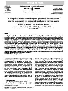
where i and j are the object pixel indices in the x and y axes, respectively; iL and jL are the indices of the lenses on the x and y axes. From Eqs. (5) and (6), we can verify that every pixel position in the elemental image plane is calculated by its own depth data L(i,j). Figure 6 shows the color images of the object and their corresponding depth map. In order to extract the region of interest in the depth map, we separated the background from the person, as shown in Figs. 6(b) and (d). It is necessary to prevent unwanted beams to come into the lens array, in the conventional optical pickup process. While we capture object and separate the background from the object to extract the region of interest, then generate elemental images. So it eased the setup conditions, and it avoided the aberrations caused by lens array, which means we can generate an elemental image from an object almost anywhere. Fig. 7 shows the elemental images plotted by the proposed method.
(a)
(b)
(c)
(d)
(5)
(6)
FIG. 5. Geometry of pixels mapping from object image plane to elemental image plane for generating elemental image pixels.
FIG. 6. Object color images and their corresponding depth map images; (a) full color image and (c) its depth map, (b) region of interest and (d) its depth map.
FIG. 7. Elemental image generated by proposed method.
384
Journal of the Optical Society of Korea, Vol. 16, No. 4, December 2012
IV. EXPERIMENT To demonstrate the proposed method, we have carried out an experiment. The implemented experimental setup is shown in Fig. 8. It is composed of a depth camera, a PC, and a high resolution LCD monitor. And the lens array is used in the reconstruction process to integrate elemental image generated by the proposed pickup method. Compared with the conventional optical pickup method, it has significantly simplified the pickup process. System parameters are listed in Table 1. In our experiment, we used a KINECT sensor as the depth camera. Recently Microsoft released a non-commercial KINECT software development kit (SDK) for Window 7. We use C# program to run the KINECT SDK, and extract each pixel’s real depth data. The depth map resolution is same with the color image, which is 320 × 240. The detectable depth range of the KINECT sensor is from 800 mm to 4000 mm. The extracted real depth range from the object which shown in Fig. 3 is from 994.9 mm to 1207.7 mm, and the real depth data of every pixel is converted by Eq. (4). The lens array used in the experiment consisted of 30(H) × 30(V) rectangular elemental lenses that are 5 mm × 5 mm with a 10 mm focal length. Furthermore the gap between the lens array and the LCD monitor is set to 11mm. In order to verify that the image generated by the proposed pickup method is also effective as a conventional optical pickup method, we captured the reconstruction image obtained by
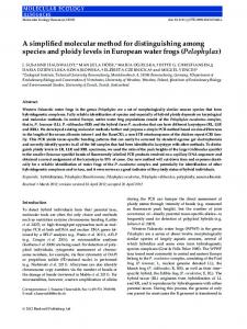
the proposed method in five different viewing positions. Fig. 9 shows the experimental result. As shown in Figs. 9(a), (c), and (e), the vertical distance y between marked pixels are 77.19 mm, 89.6 mm, and 82.1 mm, respectively. It can be confirmed that the proposed method successfully creates pixels disparity in the vertical direction. In the same way, the horizontal distance x between the marked pixels in Figs. 9(b), (c), and (d) is 30.8 mm, 47.8 mm, and 34.4 mm, respectively. It can be also confirmed that the proposed method successfully creates pixels disparity in the horizontal direction. From the experimental result, in different viewing positions we can observe the correct parallax image.
V. CONCLUSION In conclusion, a novel pickup method that generates elemental images from real objects based on integral imaging is proposed. The proposed method extracts 3D information from the object using a depth camera. Since our proposed pickup method generates elemental images without a lens array, the optical pickup process of conventional integral imaging has been simplified. Some disadvantages caused by using a lens array have been solved. If the calculation speed improved, the proposed method can be applied to a
FIG. 9. Reconstruction image using proposed pickup method and captured at five different viewing positions.
FIG. 8. Experimental setup. TABLE 1. Specifications of experimental setup Key components
Specifications
Characteristics
Lens array
Focal length Number of lenses Pitch of elemental lens
10 mm 30 (H) × 30 (V) 5 mm
Depth-camera
Model
XBOX 360 KINECT sensor
Display
Pitch of pixel Resolution
0.1245 mm × 0.1245 mm 3840 × 2400 pixels
Simplified Integral Imaging Pickup Method for Real Objects Using a Depth Camera - Gang Li et al. real-time integral imaging display [19], because of the simplified pickup process. Furthermore, it easy to obtain elemental images even from moving objects.
ACKNOWLEDGMENT This research was supported by the KCC (Korea Communications Commission), Korea, under the R&D program supervised by the KCA (Korea Communications Agency) (KCA-2012-(1191101108-110010200)) and the National Research Foundation of Korea (NRF) grant funded by the Korea government (MEST) (No. 2012-0000479).
REFERENCES 1. J. L. Fergason, S. D. Robinson, C. W. McLaughlin, B. Brown, A. Abileah, T. E. Baker, and P. J. Green, “An innovative beamsplitter-based stereoscopic/3D display design,” Proc. SPIE 5664, 488-494 (2005). 2. Y.-H. Tao, Q.-H. Wang, J. Gu, W.-X. Zhao, and D.-H. Li, “Autostereoscopic three-dimensional projector based on two parallax barriers,” Opt. Lett. 34, 3220-3222 (2009). 3. K. Choi, J. Kim, Y. Lim, and B. Lee, “Full parallax viewingangle enhanced computer-generated holographic 3D display system using integral lens array,” Opt. Express 13, 1049410502 (2005). 4. J.-L. Zhao, H. Jiang, and J. Di, “Recording and reconstruction of a color holographic image by using digital lensless Fourier transform holography,” Opt. Express 16, 2514-2519 (2008). 5. G. Lippmann, “La photographie integrale,” C. R. Acad. Sci. 146, 446-451 (1908). 6. Y. Kim, K. Hong, and B. Lee, “Recent researches based on integral imaging display method,” 3D Res. 1, 17-27 (2010). 7. G. Baasantseren, J.-H. Park, K.-C. Kwon, and N. Kim, “View angle enhanced integral imaging display using two elemental image masks,” Opt. Express 17, 14405-14417 (2009). 8. S.-g. Park, B.-S. Song, and S.-W. Min, “Analysis of image visibility in projection-type integral imaging system without
385
diffuser,” J. Opt. Soc. Korea 14, 121-126 (2010). 9. S. Yeom, Y.-H. Woo, and W.-W. Beak, “Distance extraction by means of photon-counting passive sensing combined with integral imaging,” J. Opt. Soc. Korea 15, 357-361 (2011). 10. J.-H. Park, J. Kim, Y. Kim, and B. Lee, “Resolution-enhanced three-dimension/ two-dimension convertible display based on integral imaging,” Opt. Express 13, 1875-1884 (2005). 11. Y. Kim, J. Kim, J.-M. Kang, J.-H. Jung, H. Choi, and B. Lee, “Point light source integral imaging with improved resolution and viewing angle by the use of electrically movable pinhole array,” Opt. Express 15, 18253-18267 (2007). 12. F. Okano, H. Hoshino, J. Arai, and I. Yuyama, “Real-time pickup method for a three-dimensional image based on integral photography,” Appl. Opt. 36, 1598-1603 (1997). 13. H. Navarro, R. Martinez-Cuenca, G. Saavedra, M. MartinezCorral, and B. Javidi, “3D integral imaging display by smart pseudoscopic-to-orthoscopic conversion (SPOC),” Opt. Express 18, 25573-25583 (2010). 14. A. Tolosa, R. Martinez-Cuenca, A. Pons, G. Saavedra, M. Martinez-Corral, and B. Javidi, “Optical implementation of micro-zoom arrays for parallel focusing in integral imaging,” J. Opt. Soc. Am. 27, 495-500 (2010). 15. J.-S. Jang and B. Javidi, “Improved viewing resolution of three-dimensional integral imaging by use of nonstationary micro-optics,” Opt. Lett. 27, 324-326 (2002). 16. J. Hahn, Y. Kim, E.-H. Kim, and B. Lee, “Undistorted pickup method of both virtual and real objects for integral imaging,” Opt. Express 16, 13969-13978 (2008). 17. D.-Q. Pham, N. Kim, K.-C. Kwon, J.-H. Jung, K. Hong, B. Lee, and J.-H. Park, “Depth enhancement of integral imaging by using polymer-dispersed liquid-crystal films and a dual-depth configuration,” Opt. Lett. 35, 3135-3137 (2010). 18. Y. Kim, H. Choi, J. Kim, S.-W. Cho, Y. Kim, G. Park, and B. Lee, “Depth-enhanced integral imaging display system with electrically variable image planes using polymerdispersed liquid-crystal layers,” Appl. Opt. 46, 3766-3773 (2007). 19. K.-C. Kwon, C. Park, M.-U. Erdenebat, J.-S. Jeong, J.-H. Choi, N. Kim, J.-H. Park, Y.-T. Lim, and K.-H. Yoo, “High speed image space parrael processing for computergenerated integral imaging system,” Opt. Express 20, 732-740 (2012).