Simulation of Integrated Circuit Immunity with LECCS Model Kouji ICHIKAWA1, 2, Masashi INAGAKI1, Yukihiko SAKURAI1, Isao IWASE1, Makoto NAGATA3, Osami WADA4 1
DENSO CORPORATION, R&D Center, Aichi, Japan {kouji_ichikawa, masashi_inagaki, yukihiko_sakurai, isao_iwase}@denso.co.jp 2 Kobe University, Graduate School of Science and Technology, Hyogo, Japan 3 Kobe University, Department of Computer and Systems Engineering, Hyogo, Japan
[email protected] 4 Kyoto University, Department of Electrical Engineering, Graduate School of Engineering, Kyoto, Japan
[email protected] Abstract — We have been developing an LSI model for EMC simulation in electronic control units. EMI simulations have been applied to some units using an LSI EMI model. These models have been called the LECCS Model and ICEM Model, but there are few examples of EMS simulation in printed circuit boards. Therefore , we studied the LSI EMS model and attempted to perform an EMS simulation of a printed circuit board. The LSI was tested through the DPI method (IEC61967-4). The EMS in this test system was analyzed, and the usefulness of this method of analysis was confirmed. The analysis was also applied to a product.
I. INTRODUCTION In this work, Immunity analysis for Board design is attempted using LSI’s immunity model. The target of the PCB analysis is the automobile electronic control unit (ECU). Compared with other electronic products, those used in automobiles are placed in an environment in which ECUs that emit noise are located near those that must not malfunction even if subjected to noise. EMC problems are likely to occur. This location arrangement becoming even more crowded with the increased use of electronics in automobiles. So there is also a trend toward increasingly strict regulation. Because the cost of an ECU is also decreasing, the printed circuit boards used generally have fewer layers than regular consumer products, in most cases, they are single-sided or doublesided. Number of noise suppression components that can be used is also limited. In addition, there is a trend to shorter product development times. Ensuring the EMC performance of the ECU has a great impact on product development. Automobile ECUs have become more computerized, so as to form complex electronic systems. The semiconductors (IC/LSI) supporting these systems also must have increasingly high performance. EMC problems of ECUs are affected more and more by the EMC performance of these semiconductors. Key tasks in the design in order to assure EMC performance include the selection of semiconductors with low noise and high immunity, and the investigation of the peripheral layout design of semiconductors on printed circuit boards. To analyze the noise propagation of PCB, the LSI EMI model has been examined. LSI is assumed to be a noise source, and the noise propagation route of power supply/GND pattern of PCB has been analyzed. Some
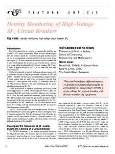
examples of the analysis can be shown. However, there are a few reports on immunity analysis using an LSI model, and especially few examples of application to PCB analysis. The present study analyzed immunity phenomena using LSI and PCB impedance [1]-[4]. The possibility of EMS analysis for PCB design using an LSI model was also investigated. II. IMMUNITY ANALYSIS AND LSI MODELING A. LSI Immunity Test The following LSI Immunity test methods are presently under discussion by the IEC: IEC62132-1: General conditions and definitions IEC62132-2: Tem-Cell and Wideband Tem-Cell Method IEC62132-3: Bulk Current Injection (BCI) method IEC62132-4: Direct RF Power Injection method IEC62132-5: Workbench Faraday Cage method In this research, the Direct RF Power Injection method (DPI)[5] is selected. It is the only method impressing a high-frequency electric power on the examination terminal for GND. As a result, it is convenient, and the test set-up can be modeled easily. EMS simulation technology including the LSI is first examined using this DPI method. Figure 1 and 2 show the measurement system. The output of the signal generator is amplified, and the signal is supplied to the DUT with the capacity coupling. The bias is supplied to the DUT through the decoupling network (inductor) so that the amplified signal will not be affected. Figure 3 shows the result of the immunity test in the test set-up presented in Figure 1. DUT malfunction was determined from the waves of the LSI output terminal. The evaluation test was conducted under the conditions shown in the figures below.
Fig. 1.
BCI test-setup
17th International Zurich Symposium on Electromagnetic Compatibility, 2006
308
17th International Zurich Symposium on Electromagnetic Compatibility, 2006
Fig. 4. Fig. 2.
Composition of LSI, PCB, and test set-up
The relation between the impressed voltages, Vdpi and Verr, in the voltage at the malfunction of LSI is one condition of Eq. (1).
LSI evaluation board
(2)
Eq. (3) can calculate Vdpi from the relation between Vcc and Vs and using the measured Verr. (3) The potential in terminal LSI when a constant voltage is impressed is calculated beforehand. Next, assuming the system is linear, and the terminal voltage at which the LSI malfunctions is converted into the voltage at the injection port. As a result, it is thought that analyzing the DPI test is feasible. (The relation of Vcc, Vs, Verr and Vdpi are actually shown by Eq. (3), although it does not become an impedance model as simple as Z1 and Z2.) The parameters needed at this time are the following three: 1. Impedances of LSI 2. Impedances of test set-up such as Z1 and Z2. 3. Malfunction voltage of LSI shown in Verr. These parameters are acquired and the possibility of the analysis is examined. The internal impedance of the LSI has already been examined at the EMI simulation [6][7]. This is because the LSI used in this analysis is the same, and the same result can be used. Figure 5 shows the internal impedance of LSI.
Terminal to be tested: 5V power supply terminals (VCC_5A,VCC_5B) Test frequency: 100 kHz - 1 GHz㩷 Fig. 3.
Immunity Test Result
㩷
This LSI has a 3.3V power supply terminal. But it was not tested, because the DUT had an internal voltage regulator (5V->3.3V) circuit was not connected to the power line of the other circuit on PCB. The immunity of this LSI became lower at 1 – 2 MHz, and at 200 – 600 MHz according to Figure 3. Immunity levels are different from VCC_5A and VCC_5B at 10 MHz or less. However, at 100 MHz or more, the immunity levels are the same. B. LSI immunity Analysis Next, we attempt to simulate the test results shown in figure 3. It can be presumed that the voltage impression or the current injection to the terminal is a cause of LSI malfunction. When the current is impressed on the power supply terminal, it is converted into voltage by internal impedance of LSI. It is thought that the voltage generated at the terminal becomes the parameter for the judgment of malfunction, so this parameter is used and the analysis is made. A model like figure 4 can be assumed when approaching this DPI method examination. The relation of voltage (Vs) generated when injecting it from a highfrequency electric power source (RF), and the voltage (Vcc) of the LSI of the power supply terminal can be shown by Eq. (1).
Fig. 5.
(1) 309
Impedances of LSI
17th International Zurich Symposium on Electromagnetic Compatibility, 2006
TABLE I IMPEDANCES OF LSI
Fig. 8.
Voltage of terminal when LSI malfunctions (160-300 MHz)
C. Immunity Analysis at LSI level Fig. 6.
Impedances of test set-up including the DUT
Next, We attempt to analyze the impedances of the set-up in Figure 1. Figure 6 shows the impedance characteristics of the test set-up including DUT. The impedance decrease with 10 MHz, the resonance of the test set-up’s inductance and capacity of the internal LSI internal impedance are a cause. The resonance by 100 MHz or more is thought to be the impedance of the test set-up. Figure 5 shows the modeling of the test set-up in which this characteristic was reflected by using the impedance model of LSI. We then evaluate the malfunction voltage of the LSI. From testing with the set-up shown in Figure 1, the result of measuring Verr at the power supply terminal of LSI is shown in Figure 7. This result is a voltage of the terminal VCC_5B when LSI malfunctions. The malfunctioning frequency domain was on the low-frequency side of 10 MHz or less and the high-frequency side of 100 MHz or more. A steady evaluation could not be done on the highfrequency side. However, it was steady from 4Vp-p to 5Vp-p on the low-frequency side. The evaluation on the high-frequency side examines whether the malfunction mode of LSI is different from the case of 10 MHz or whether there is no problem in the test.
Fig. 7.
The EMI simulation is conducted at the evaluation board and LSI level. The RF power source is connected with the set-up with the impedance characteristic of Figure 6 including the impedance model of LSI of Figure 5, and voltage Vcc of the LSI terminal caused at this time is calculated. Next, the quotient of each frequency with the malfunction voltage Verr of LSI obtained in Figures 7 and 8 is calculated, and Vdpi is analyzed. At this time, Verr does not have a constant value as shown in Figures 7 and 8. This makes for a complex analysis. It is calculated with two Verr and analyzed with two voltages, 5V and 4V. Figure 9 compare the test results with those for immunity in Figure 3. The tendency in the level of immunity tested by the DPI method has been calculated, and the correspondence is good, but several reasons for the lower simulation accuracy are conceivable. 1. Accuracy of impedance model in Figure 6 2. Measurement accuracy of malfunction judgment voltage in Figure 7 and 8. Those are not constant value. 3. The malfunction mechanism is complex and the parameter to calculate it are lacking. It is necessary to further examine the malfunction mechanism of LSI in order to improve the accuracy of the simulation result as stated above, and the appropriate range to apply this analytical method must be investigated.
Voltage of terminal when LSI malfunctions (0.16-10 MHz) Fig. 9. 310
Simulation result of DPI test
17th International Zurich Symposium on Electromagnetic Compatibility, 2006
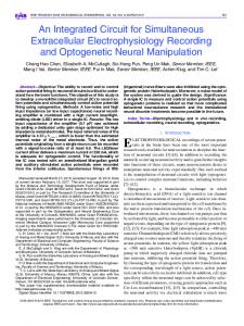
III. EXPANSION WITH PCB ANALYSIS Semiconductors such as LSI and sensors are nonlinear element and become a trigger of malfunctions. There is a great demand for the analytical technology to understand and improve EMS performance. PCBs in theses products have many components and a complex layout. Therefore, the impedance characteristic of the PCB becomes complex, and analytical accuracy might be compromised was feared, Application to automotive electronic equipment was tried and the accuracy was verified. Targeted ECU is a two-sided PCB and the size is 110 mm × 92.5 mm. The LSI power source and wiring harness were selected and analyzed. In designing the power supply to the LSI and the route to the terminal GND, not only the power supply system wiring but also the injections of LSI into the I/O terminal from the signal line were included. Attention was paid to the power supply system design since confirming coverage of the model is an aim, and in some cases immunity level improves by changing the design of the power supply system. The analytical result of the DPI method is shown in Figure 10 using results just like those of the abovementioned analysis of the PCB impedance. In the present PCB product analysis, to easily cause a malfunction, the analysis/measured was performed the same as at the time of single LSI analysis, with the capacitors excluded. It is analyzed with the malfunction level Verr=5Vp-p and 4Vp-p as well as LSI mentioned before. There was no malfunction in the analysis at 100MHz, but at 10MHz the simulation value and measurement trend coincided. This is one reason for the low accuracy of the impedance model of the measurement system including the circuit boards. Moreover, the result of analyzing the current route when injection power of 5MHz is impressed is shown in Figure 11. The injection power reached LSI when the capacitor was not installed in the PCB, causing the malfunction. However, the return path was formed when the capacitor was installed, the invasion of the current disappeared even as for LSI, and no malfunction was caused. If the route of entry can be analyzed like this, the immunity can be improved.
Fig. 11.
IV. CONCLUSION A method for analyzing the DPI method using simulation was examined. In this study we considered how to analyze the LSI EMS model based on the EMI model. An impedance characteristic that contained LSI and its voltage malfunction were necessary to simulate it. This parameter was used and analyzed. Although the accuracy was far from sufficient, qualitatively was not a problem, and the effectiveness of the basic approach was recognized. In future study, together with due consideration of ways to improve accuracy, we intend to investigate simulations of other immunity test methods as well. This is method was applied to a power supply system analysis of a complex product PCB at a lowfrequency power of 10 MHz. As a result, validation of effectiveness was possible in analyzing the malfunction at a low frequency, but the accuracy was lower as the frequency became higher. We took this to incident the near impossibility of parameters sufficient to express the mechanism of the malfunction.
References [1] [2]
[3] [4] [5] Fig. 10.
Simulation result of DPI test at product PCB level
[6] [7]
311
RF propagation analysis of PCB product level
E. Takahashi, et al., "Evaluation of LSI Immunity to Noise Using an Equivalent Internal Impedance Model," EMC Europe 2002 Int. Symposium on EMC, pp. 487-492, Sep. 2002. K. Ichikawa, et al., "EMI Analysis of a PCB for Automotive Equipment Using an LSI Power Current Model," 4th Int. Workshop on EMC of Integrated Circuits (EMC Compo 04), pp. 38-42, Angers, April 2004. F. Lafon, et al., ”ICEM-ICIM Modeling and Exploitation for Bus Transceivers Applications”, 4th Int. Workshop on EMC of Integrated Circuits (EMC Compo 04), pp.123-128, Apr. 2004. S. Baffreau, et al., “Re-use of ICEM for immunity simulation”, EMC Zurich 2005, pp. 659-677, Feb. 2005 IEC 62132-4 Integrated Circuits - Measurement of Electromagnetic Immunity - 150 kHz to 1 GHz - Part 4: Direct RF Power Injection Method. Y. Mabuchi, et al., “LECCS (Linear Equivalent Circuit and Current Source) Modeling Technique for ICs”, EMC Zurich 2005, pp. 781-799, Feb. 2005 K. Ichikawa, et al., “A Study on Measurement of LSI Immunity for PCB Analysis”, IEICE Tech. Rep., EMCJ2004-115, pp. 77-82, Dec. 2004, (in Japanese).