In this report we propose a slice-based volume rendering algorithm which attempts to address this goal. We describe both the basic algorithm and several ways ...
Ohio State University Technical Report OSU-ACCAD-1/93-TR1, January 1993.
Slice-Based Volume Rendering J. Edward Swan II ½ ¾
Roni Yagel¾
½ Department of Computer and
¾ The
Information Science Advanced Computing Center for the Arts and Design The Ohio State University
Abstract A current goal in volume graphics is a volume rendering algorithm that provides an elegant and controllable tradeoff between image quality and rendering speed. In this report we propose a slice-based volume rendering algorithm which attempts to address this goal. We describe both the basic algorithm and several ways that it can operate in an incremental and an adaptive manner.
1
Introduction
The proposed sliced-based algorithm attempts to apply volume rendering to real-time, interactive graphics. Volume rendering is fundamental to volume visualization, which deals with the communication of diverse volumes of data including scalar, vector, tensor, and multi-modal [Elvins92] and is fundamental to all scientific fields. Although a real-time volume rendering algorithm would be of general value, a virtual medical environment is the current motivation of this research. Such environments are currently used for diagnostic medicine, surgical planning for orthopedic prosthesis, and radiation treatment planning. The bottleneck in these applications is rendering 3D images [DeFanti87]. In addition such an environment would be useful for general medical diagnoses and planning, as well as education. We especially see value in the training of medical students in areas such as anatomy where either the anatomical structures are difficult to visualize from the 2D cues used in standard textbooks, or examples of anatomical structures do not correspond to real structures in humans, as results from the use of models or cadavers. To support the goal of real-time volume rendering, the algorithm needs to have the following features: 1. The rendering must occur in “real time” where this is defined as quick enough that a user has a sense of interaction. If necessary the algorithm must tradeoff image quality for rendering speed. As hardware inevitably becomes faster this tradeoff will become less and less deleterious to image quality. 2. The rendering must be incremental or adaptive. For speed a lower quality image may be displayed at first, but then the algorithm must be able to enhance image quality at the expense of further CPU resources. 3. The rendering must occur in the background during user pauses. The effect should be a (possibly) lower-quality image that appears immediately but which is replaced by a higherquality image if the user does not change the viewing parameters for a length of time.
2
Background
Numerous volume rendering algorithms have been proposed. These can be classified into two broad categories based on the primitive
rendered: surface fitting and direct volume rendering. In addition, the direct volume rendering algorithms can be further classified by the general approach used: forward projection, backward projection, and hybrid methods [Elvins92].
2.1 Surface Fitting A class of volume rendering algorithms fit a 2D surface to points in the volume with a particular data value, and then render this surface. Among the early techniques are the opaque cube or cuberille methods [Herman79], where voxels containing the data value of interest are rendered as small individual cubes. Another early technique is contour-connecting [Keppel75] [Fuchs77], where closed contours at the data value are traced in adjacent volume slices and then connected with a 2D surface. A current and widely used method is marching cubes [Wyvill86] [Lorensen87], where cubes are fit to the data value of interest and then tessellated with triangles. Closely related are the marching tetrahedra [Shirley90] and dividing cubes [Cline88] algorithms which instead of cubes fit the data with tetrahedra and sub-pixel sized points respectively. All surface fitting algorithms have the good property that once the surface is fitted it can be quickly rendered with current graphics hardware. They all suffer, however, in that they can only display discrete data values; they are poor methods for visualizing a range of values. And they suffer from sampling errors and artifacts, such as false positive and false negative values, which can be incorrectly interpreted as valid data.
2.2 Direct Volume Rendering Another class of volume rendering algorithms directly render each voxel as a small cube of a semi-transparent material. These cubes are drawn onto the image plane, with the contribution of each attenuated according to the cube’s distance from the image plane — closer cubes are attenuated by a small amount, while distant cubes are attenuated more. Thus the final image does not contain a hard or explicit surface, but instead appears to be constructed from layers of semi-transparent gels. Since they do not attempt to fit a surface, direct volume rendering algorithms can be implemented free of the sampling errors that arise when a binary decision is made about the existance of a surface at each voxel. They are also well suited to display a range or a smooth variance of data values, and they can display thin, wispy objects that would be difficult to fit with a surface. They suffer the disadvantage that rendering requires processing every voxel in the data set. 2.2.1 Forward Projection Forward projection direct volume rendering algorithms operate in object order: they process the voxels of the volume sequentially and access the pixels of the image plane in random order. Two approaches are the splatting [Westover90] and the v-buffer [Upson88] methods. These transform each voxel into image coordinates, and then determine the pixels on the image plane covered by the voxel’s
Ohio State University Technical Report OSU-ACCAD-1/93-TR1, January 1993. Image Plane
projection. The image is thus composited voxel by voxel on the image plane. With the slice shearing [Drebin88] method, the entire volume is first transformed into the viewing pyramid, and then resampled into image coordinates. Then each slice parallel to the image plane, starting with the rear, is composited with the slice immediately in front, until composition with the first slice results in the rendered image.
Cut Planes Eye Point Volume
2.2.2 Backward Projection Backward projection or ray tracing direct volume rendering algorithms operate in image order: they process the pixels of the image plane sequentially and access the voxels of the volume in random order. Among the methods are [Tuy84], [Levoy88], [Upson88], and [Levoy90]. These algorithms transform a ray from each pixel into object coordinates, and then calculate the pixel’s value by compositing the voxels intersected by the ray. The contribution of each voxel is attenuated according to it’s distance along the ray; farther voxels are attenuated more than closer voxels. A backward projection algorithm may not visit every voxel in the volume, especially if the rays are divergent as happens with a perspective viewpoint. In this case every voxel in the data set is not visited and hence the algorithm may run faster than a forward projection approach. However in some sense the resulting image is not as “good” as a forward projection in that the image is less accurate since it is based on less information (fewer voxels). The resolution of backward projection can be increased so that the rays visit every voxel, but in this case the complexity becomes equivalent to that of forward projection — every voxel must be visited to render the image; the order of this visitation is the only difference.
View Ray
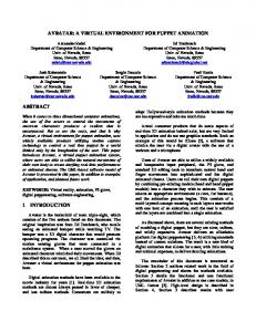
Figure 1: Construction of view ray and cut planes.
Cut Plane
View Ray
Polygons 2.2.3 Hybrid Methods A hybrid method with respect to the methods above is one that operates in neither strict object nor strict image order, but instead in some intermediate order. The sliced-based method proposed in this report falls into this category.
3
Figure 2: Intersecting a cut plane to produce polygons.
Basic Algorithm
The sliced-based algorithm represents a new method of combining forward and backward projection. The image plane is projected into and intersected with the volume at regular intervals. The result is a list of polygons parallel to the image plane that can be rendered with any polygon rendering engine. The algorithm consists of the following steps:
�
�
� � � remains fixed, and all the cut the normal vector planes are produced by varying �. This may facilitate intersecting the cut planes with the volume. 3.2 Intersect Cut Planes
1. Project image plane to produce cut planes.
In the second stage of the algorithm, each cut plane is intersected with the voxels of the volume (see figure 2). A polygon is produced at the intersection between the cut plane and each voxel. Figure 3 details the formation of a polygon from the intersection of a cut plane with a voxel. The color and normal of each polygon vertex are determined by interpolation from the two nearest voxel vertices. Considerations:
2. Intersect cut planes with volume to produce polygon list. 3. Render polygon list.
3.1 Calculate Cut Planes In the first stage of the sliced-based algorithm the view ray is constructed. It originates at the eye point and passes though the center of the volume. At intervals along this ray cut planes are produced. These planes are perpendicular to the view ray and parallel to the image plane (see figure 1). Considerations:
¯ An efficient cut plane-voxel intersection algorithm is needed — we don’t want to consider each voxel separately, which would be ���¿ �. The implicit plane equation can be used to tell which side of a cut plane a given voxel is on. This suggests running down a beam of voxels along one axis of the volume raster to find where the beam intersects the cut plane. Then a filling algorithm can be used to find other voxels intersected by the same cut plane, such as those that appear in [Yagel92] and [Fujimoto86].
¯ The view ray forms the normal of all the cut planes. Thus from the implicit equation for a plane
� �� �� � � � 2
Ohio State University Technical Report OSU-ACCAD-1/93-TR1, January 1993. ¯ To solve the hidden voxel problem the list of polygons must be rendered semi-transparently in front-to-back order. This must be supported by the rendering hardware.
Voxel Vertex
4
Adaptive/Incremental Considerations
�� �
Forward projection algorithms are �¿ complexity, since they process each voxel. Backward projection algorithms are O �¿ , and also �¿ if every voxel in the volume is sampled by (at least one) ray. Hopefully the sliced-based algorithm can operate in an adaptive/incremental manner and therefore beat this �¿ com¿ plexity. Even if it cannot do better than � then perhaps it can still adapt the � to allow real-time interaction. If there are enough cut planes that every voxel is intersected by at least one of them, then the sliced-based algorithm becomes comparable to a forward projection algorithm, and the two methods should produce identical images. This suggests a possible evaluation criteria: when applying adaptive/incremental techniques when is the generated image identical to one produced by a forward projection algorithm? As the sliced-based algorithm adaptively/incrementally decreases the sampling rate of the volume when does the image begin to degrade? Comparing the generated image pixel by pixel with one rendered from a forward projection algorithm can serve as an image quality metric.
Polygon Vertex
� �
�� �
Voxel Vertex
�� �
�� �
Polygon
Figure 3: Formation of a polygon.
Normal Color Generated Polygon
4.1 Volume Resolution
Figure 4: A normal and a color are produced for each polygon vertex. Normals of polygon vertices will not necessarily be coplanar.
A powerful method to speed up the algorithm is to incrementally alter the resolution of the volume raster. First the sliced-based algorithm is applied to a low-resolution volume (e.g. ¿ ) and then to ¿ successively greater resolutions ( ¿ � ), etc. The rendering of the lower resolutions directly affects the � in the complexity metric and will lead to increased performance at the cost of image quality. Considerations:
� ��
¯ Coherency is available between successive voxels intersected with the same cut plane — polygon vertices and edges are shared between adjacent intersected voxels. The sliced-based algorithm must take advantage of this for efficiency considerations.
��
¯ Building these lower resolution rasters is a ���¿ � task for each (although the � will shrink each time), which implies that they must be pre-calculated before rendering begins. The original raster could either be resampled with a voxel grid of arbitrary resolution or the 8 vertices of each voxel could be averaged into 1 vertex.
¯ The intersection of a cut plane with each voxel will produce a series of intersection possibilities similar to those encountered in the marching cubes algorithm [Lorensen87]. Marching cubes uses a case table to efficiently handle the different intersection possibilities. A similar structure can be used for the sliced-based method.
¯ This method also uses more memory than just keeping the original raster. ¯ This method is superior to methods that adapt to measures of image plane complexity such as [Levoy90b] or [Whitted80]. These methods point sample the volume raster and therefore can miss small but bright objects. In contrast, with this method the lower resolution rasters contain all the object information, abet in a low (blurry) resolution manner.
3.3 Render Polygons In the third stage of the algorithm, the polygons produced from the second stage are rendered with a polygon rendering engine. For speed a hardware polygon renderer will be used. Considerations:
4.2 Sampling Distance Between Cut Planes
¯ The sliced-based algorithm assumes the partial volume effect, and thus the values at the vertices of the voxels represent point samples of a continuously varying 3D scalar field. The algorithm will not render volumes of boolean voxels.
The second method to reduce complexity is to alter the distance Ô between cut planes. Each cut plane is expected to contribute O( �¾ ) to the time complexity (see section 5.1). As the distance between them rises and fewer cut planes are used the algorithm will become faster.
�
¯ Because of the partial volume effect, both the color and the normal at each polygon vertex will be determined by interpolation from surrounding voxels (see figure 4) as opposed to calculated from the polygon itself. Thus as the polygon is rendered it will be necessary for the polygon renderer to interpolate both the normal and the color across the face of the polygon — e.g. both Gaoraud and Phong shading must be supported by the rendering hardware.
4.2.1 Periodic Sampling The interval at which cut planes are produced along the view ray can be varied. It could be regular (figure 5a), or the portion of the volume closest to the eye point could be sampled more frequently than the farther portion (figure 5b), or other sampling methods could be devised.
3
Ohio State University Technical Report OSU-ACCAD-1/93-TR1, January 1993.
Cut Plane
(a) (a)
(b)
(b)
Figure 5: Sampling rate of cut planes in volume raster.
4.2.2 Adaptive Sampling Another method is to only sample those slices of the volume raster that contribute the most to the final image. This would quickly build image quality by intelligent placement of cut planes. Once the image quality reaches a certain threshold, the algorithm would forego the remaining cut planes. For example the algorithm could sample the raster sparsely (figure 5a) and then fill in the gaps based on the object complexity of different areas of the volume raster. Considerations:
(c)
Figure 6: Adapting the number of polygons generated from each cut plane. (a) The cut plane in the volume raster. (b) Sparse point samples in the cut plane. (c) Additional point samples adaptively added. (d) The samples tessellated into polygons.
¯ This method requires some sort of complexity measure of the voxel data set. This measure would be taken as polygons are formed from each cut plane.
Ô plane will be O( �¾ ), as this is an upper bound on the number of voxels intersected by a plane intersecting a voxel raster at an arbitrary angle.
�
4.3 Sampling Within a Cut Plane The third method to reduce complexity is to alter the number of polygons which Ô are produced from each cut plane. This would reduce the O( �¾ ) complexity per cut plane (see section 5.1).
5.2 Compare with Levoy’s Criteria
�
[Levoy90b] describes a method to adaptively refine images of raytraced volume data. He critiques his method with 3 criteria of refinement techniques for adaptive rendering environments. The sliced-based method analyzed by these criteria yields:
4.3.1 Adaptive Polygon Generation Each cut plane can be adaptively sampled like the Whitted method of adaptive supersampling of ray-traced scenes [Whitted80], as detailed in figure 6.
1. Work is distributed according to where it makes the most difference. This is addressed in two ways: 1) the adaptive consideration of where to place the cut planes and 2) the adaptive formation of polygons within each cut plane.
4.3.2 Generating One Polygon per Voxel As described in section 3 and figure 2, the cut plane can generate one polygon for every voxel it intersects. Considerations:
2. Intermediate images are formed from partial information. This is addressed in two ways: 1) sampling lower resolution rasters and 2) viewing each cut plane as it is calculated, e.g. the user views the image plane continuously as each cut plane is composited with it. For example in figure 5b the volume raster is sampled more frequently in the areas close to the view point, which may provide adequate image quality even though the whole volume raster has not been sampled. The user would see these cut planes composited with the image plane in front-to-back order.
¯ The previous methods form a tradeoff between the number of polygons produced, which affects time, and the sampling density of the cut plane, which affects image quality. However, it is likely that the one polygon per voxel method can be based on integer operations, while the adaptive polygon generation method will be based on floating point operations. Thus the overhead of adaptive polygon generation may make it no faster than generating one polygon per voxel.
5
(d)
3. The amount of work discarded after the formation of each image is minimized. This is not addressed by the slicedbased method.
Discussion
5.1 Algorithm Complexity
5.3 Image versus Object Complexity
The complexity of generating the view ray and the cut planes should be negligible; perhaps a function of one dimension of volume size (O(�)). I believe the complexity of generating polygons from a cut
Existing adaptive refinement algorithms (e.g. [Levoy90b] [Whitted80]) use measures of image complexity to drive where effort is extended in rendering the image. In contrast, the proposed
4
Ohio State University Technical Report OSU-ACCAD-1/93-TR1, January 1993.
References
Image Plane
Eye Point
Volume
[Cline88]
Cline, H.E., Lorensen, W.E., Ludke, S., Crawford, C.R., and Teeter, B.C., “Two Algorithms for Threedimensional Reconstruction of Tomograms”, Medical Physics, Volume 15, Number 3, May/June 1988, pages 320–327.
[DeFanti87]
DeFanti, T.A., Brown, M.D., and McCormick, B.H. (ed), “Special Issue on Visualization in Scientific Computing”, Computer Graphics, Volume 21, Number 6, November 1987, ACM SIGGRAPH: New York, page A4.
[Drebin88]
Drebin, R., Carpenter, L., and Hanrahan, P., “Volume Rendering”, Computer Graphics (SIGGRAPH ’88 Proceedings), Volume 22, Number 4, August 1988, pages 65–74.
[Elvins92]
Elvins, T.T., “A Survey of Algorithms for Volume Visualization”, Computer Graphics, Volume 26, Number 3, August 1992, pages 194–201.
[Fuchs77]
Fuchs, H., Kedmen, Z., and Uselton, S., “Optimal Surface Reconstruction from Planar Contours”, Communications of the ACM, Volume 20, Number 10, October 1977, pages 693–702.
Cut Plane
1D Template 2D Template View Ray
Figure 7: Using templates to intersect a cut plane with the volume raster. The view ray is determined by a 1D template, from which the 2D template of the cut plane samples the volume.
adaptive refinements to the sliced-based algorithm use measures of object complexity to drive where additional effort is placed. Thus the sliced-based algorithm adapts to the 3D volume itself, as opposed to the volume’s 2D projection. Since there is much more data in a 3D than a 2D extent, we expect this adaptation to be more accurate.
5.4 Future Enhancements
[Fujimoto86] Fujimoto, A., Tanaka, T., and Iwata, K., “ARTS: Accelerated Ray-Tracing System”, IEEE Computer Graphics and Applications, April 1986, pages 16– 26.
5.4.1 Use of Templates
[Herman79]
Herman, G.T. and Liu, H.K., “Three-Dimensional Display of Human Organs from Computed Tomograms”, Computer Graphics and Image Processing, Volume 9, Number 1, January 1979, pages 1–21.
[Keppel75]
Keppel, E., “Approximating Complex Surfaces by Triangulation of Contour Lines”, IBM Journal of Research and Development, Volume 19, Number 1, January 1975, pages 2–11.
[Levoy88]
Levoy, M., “Display of Surfaces from Volume Data”, IEEE Computer Graphics and Applications, Volume 8, Number 3, March 1988, pages 29–37.
[Levoy90]
Levoy, M., “Efficient Ray Tracing of Volume Data”, ACM Transactions on Graphics, Volume 9, Number 3, July 1990, pages 245–261.
[Levoy90b]
Levoy, M., “Volume Rendering by Adaptive Refinement”, The Visual Computer, Volume 6, Number 1, February 1990, pages 2–7.
Intersecting each cut plane with the volume raster could use a 2D template (figure 7), similar to the templates from [Yagel92]. Such a template would only have to be computed once for a given view and volume raster resolution, and then could be “slid” into the volume along the view ray. Since the production of polygons from a cut plane intersection will dominate processing time, efforts to expedite this section of the algorithm are important. These templates determine sample positions from look-up tables, and are thus based on integer operations whereas other methods are based on floating point operations. This is expected to yield speed benefits. 5.4.2 Support for Perspective Viewpoint As described, the sliced-based method yields an orthogonal view of the volume raster (figure 1). However, it could also support a perspective viewpoint by scaling the polygons according to a perspective transformation — those close to the viewpoint would be larger, while those far away would be smaller. The [Drebin88] method achieves a perspective view in a similar manner: it uses the perspective transformation to resample the volume raster.
[Lorensen87] Lorensen, W.E. and Cline, H.E., “Marching Cubes: A High Resolution 3D Surface Construction Algorithm”, Computer Graphics (SIGGRAPH ’87 Proceedings), Volume 21, Number 4, July 1987, pages 163–169.
5.4.3 Use of Existing Polygon List When the viewpoint changes, the whole sliced-based algorithm is repeated — the volume raster is resampled with cut planes and a new polygon list is generated. In particular the old polygon list from the former view point is thrown away. It may be possible to reuse these old polygons. When the viewpoint changes, they could be rotated and scaled to yield a quick yet lower-quality image. The user could view this while the new polygon list is generated. As soon as they were ready a higher-quality image from the new polygon list would replace the image from the old.
5
[Shirley90]
Shirley, P. and Tuchman, A., “A Polygonal Approximation to Direct Scalar Volume Rendering”, Computer Graphics, Volume 24, Number 5, November 1990, pages 63–70.
[Tuy84]
Tuy, H.K. and Tuy, L.T., “Direct 2-D Display of 3D Objects”, IEEE Computer Graphics and Applications, Volume 4, Number 10, October 1984, pages 29–33.
Ohio State University Technical Report OSU-ACCAD-1/93-TR1, January 1993. [Upson88]
Upson, C. and Keeler, M., “The V-Buffer: Visible Volume Rendering”, Computer Graphics (SIGGRAPH ’88 Proceedings), Volume 22, Number 4, August 1988, pages 59–64.
[Westover90] Westover, L., “Footprint Evaluation for Volume Rendering”, Computer Graphics (SIGGRAPH ’90 Proceedings), Volume 24, Number 4, August 1990, pages 367–376. [Whitted80]
Whitted, T., “An Improved Illumination Model for Shaded Display”, Communications of the ACM, Volume 23, Number 6, June 1980, pages 343–349.
[Wyvill86]
Wyvill, B., McPheeters, C. and Wyvill, G., “Data Structure for Soft Objects”, The Visual Computer, Volume 2, Number 4, August 1986, pages 227–234.
[Yagel92]
Yagel, R., and Kaufman, A., “Template-Based Volume Viewing”, Proceedings EUROGRAPHICS’92, 1992, pages 157–168.
6