The slicer then computes an architec- tural slice and forward slice with respect to the crite- rion and outputs it to the maintainer. An architectural slice is a partial ...
Slicing Software Architectures3 Jianjun Zhao Department of Computer Science and Engineering Fukuoka Institute of Technology zhao@cs. t.ac.jp Applying slicing technique to software architectures promises bene t for software architecture development at least in two aspects. First, architectural understanding and maintenance should bene t from slicing. When a maintainer wants to modify a component or connector in an architectural description of a software system in order to satisfy new design requirement, he/she must rst investigate which components or connectors will a�ect the modi ed component or connector and which components or connectors will be a�ected by the modi ed component or connector. By using a slicing tool on its architectural description, he/she can extract the parts of the description containing those components and connectors that might a�ect the modi ed component or connector and might be a�ected by the modi ed component or connector. The slicing tool which provides such information can assist the maintainer greatly. Second, architectural reuse should bene t from slicing. While reuse of code is important, in order to make truly large gains in productivity and quality, reuse of software designs and patterns may o�er the greater potential for return on investment. By slicing an architectural description of a software system, a system designer can extract reusable architectures from it, and reuse them into new system designs for which they are appropriate.
Abstract
This paper introduces a new form of slicing, named architectural slicing, to aid architectural understanding and reuse. In contrast to traditional slicing, architectural slicing is designed to operate on the architectural description of a software system, rather than the source code of a program. Architectural slicing provides knowledge about the high-level architecture of a software system, rather than the low-level implementation details of a program. 1
Introduction
Software architecture is receiving increasingly attention as a critical design level for software systems [16]. The software architecture of a system de nes its highlevel structure, exposing its gross organization as a collection of interacting components. A well-de ned architecture allows an engineer to reason about system properties at a high level of abstraction. Architectural description languages (ADLs) are formal languages that can be used to represent the architecture of a software system. They focus on the high-level structure of the overall application rather than the implementation details of any speci c source module. Recently, a number of architectural description languages have been proposed such as ACME [8], Rapide [10], and UniCon [15] to support formal representation and reasoning of software architectures. As software architecture design resources (in the form of architectural descriptions) are going to be accumulated, the development of techniques to support understanding, testing, reengineering, maintenance, and reuse of software architectures will become an important issue. One promising way to support software architecture development is to use slicing technique. Program slicing, originally introduced by Weiser [18], is a decomposition technique which extracts program elements related to a particular computation. A program slice consists of those parts of a program that may directly or indirectly a�ect the values computed at some program point of interest, referred to as a slicing criterion. The task to compute program slices is called program slicing. We refer to this kind of slicing as traditional slicing to distinguish it from a new form of slicing introduced later. Traditional slicing has been studied primarily in the context of conventional programming languages [17]. In such languages, slicing is typically performed using dependence graph representations [4, 9, 6, 14, 19, 20]. Traditional slicing has many applications in software engineering activities including program understanding [5], debugging [1], testing [2], maintenance [7], reuse [13], reverse engineering [3], and complexity measurement [14]. 3 Technical
While slicing is useful in software architecture development, existing slicing techniques for conventional programming languages can not be applied to architectural descriptions straightforwardly due to the following reasons. First, the traditional de nition of slicing is concerned with slicing programs written in conventional programming languages which primarily consist of variables and statements/clauses as their basic language elements, and the slicing notions are usually de ned as (1) a slicing criterion is a pair (s, V) where s is a statement/clause and V is a set of variables de ned or used at s, and (2) a slice consists of only statements/clauses. However, in an architectural description language, the basic language elements are components and connectors, but neither variables nor statements/clauses as in conventional programming languages. Therefore, to slice architectural descriptions, new de nition of slicing must be given. Second, existing techniques for computing slices of a conventional program are topically performed using dependence graph representations which can be used to represent program dependences in a program. Usually, there are two types of program dependences in a conventional program, i,e., control dependences representing the control conditions on which the execution of a statement or expression depends and data dependences representing the ow of data between statements or expressions. However, the dependences in a conventional program are basically de ned between statements or variables, but neither com-
Report 97-SE-117, pp.85-92, Information Process-
ing Sociaty of Japan, November 1997.
85
ponents nor connectors as in architectural description languages. Moreover, in addition to the de nition/use binding relationship, an architectural description language usually support more broad and complex relationships between components and/or connectors such as pipes, event broadcast, and client-server protocol. As a result, new types of dependence relationships between components and/or connectors in an architectural description must be studied in order to compute an architectural slice. In this paper, we introduce a new form of slicing, named architectural slicing. In contrast to traditional slicing, architectural slicing is designed to operate on an architectural description of a software system, rather than the source code of a program. Architectural slicing provides knowledge about the high-level architecture of a software system, rather than the low-level implementation details of a program. Abstractly, our slicing algorithm takes as input an architectural description (written in its associated architectural description language) of a software system, then it removes from the description those components and connectors which are not necessary for ensuring that the semantics of the description of the system is maintained. This bene t allows unnecessary components and connectors to be removed at architectural level of the system which may lead to considerable space savings, especially for largescale software system consisting of numerous components. In order to compute an architectural slice, we present software architectural dependence graph to explicitly represent various types of dependences in an architectural description of a software system. Based on the graph, we give a two-phase algorithm to compute an architectural slice. The purpose for development of architectural slicing is quite di�erent from that for development of traditional slicing. While traditional slicing was designed originally for supporting source code level understanding and debugging of a conventional program, architectural slicing was primarily designed for supporting architectural level understanding and reuse of a largescale software system. However, just as traditional slicing has many other applications in software engineering activities, we believe that architectural slicing has also useful in other software architecture development activities including architectural testing, reverse engineering, reengineering, and complexity measurement. The rest of the paper is organized as follows. Section 2 brie y introduces the ACME: an architectural description language. Section 3 de nes some notions about slicing software architectural descriptions. Section 4 presents three types of dependences in an architectural description and a dependence graph. Section 5 gives a two-phase algorithm for computing an architectural slice. Concluding remarks are given in Section 6. 2
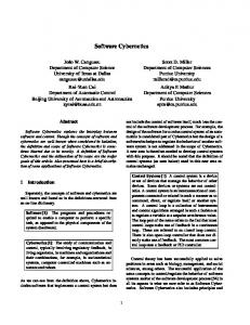
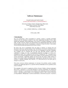
for a wide variety of architecture tools." [8] There are seven design elements in ACME that can be used to represent software architectures which include components, connectors, systems, ports, roles, representations, and bindings. Among them, the most basic elements of architectural description are components, connectors, and systems. Readers can refer [8] for more details of the language description, and we brie y introduce these design elements here. Components are used to represent the primary computational elements and data stores of a system. Intuitively, they correspond to the boxes in box-and-line descriptions of software architectures. Typical examples of components include clients, servers, lters, objects, and databases. Each component has its interface de ned by a set of ports. A component may provide multiple interfaces by using di�erent types of ports. Each port identi es a point of interaction between the component and its environment. A port can represent a simple interface such as procedure signature, or more complex interfaces, such as a collection of procedure calls that must be invoked in certain speci ed orders, or an event multi-cast interface point. Connectors are used to represent interactions between components. Connectors mediate the communication and coordination activities between components. Intuitively, they correspond to the lines in box-and-line descriptions. connectors may represent simple forms of interaction, such as pipes, procedure calls, event broadcasts, and also more complex interactions, such as a client-server protocol or a SQL link between a database and an application. Each connector has its interface de ned by a set of roles. Each role of a connector de nes a participant of the interaction represented by the connector. Connectors may have two roles such as the caller and callee roles of an RPC connector, the reading and writing roles of a pipe, or the sender and receiver roles of a message passing connector, or more than two roles such as an even broadcast connector which might have a single event-announcer role and an arbitrary number of event-receiver roles. Systems represent con gurations of components and connectors. Figure 2 (a) shows the ACME architectural description of a simple London Ambulance Service dispatch system (LAS system) which is taken from [12], and Figure 1 (a) shows its architectural representation. The architectural representation contains ve components which are connected by six connectors. For example, in the representation, the component call_entry and the component incident_mgr is connected by the connector call_info_channel. Each component is declared to have a set of ports, and each connector is declared to have a set of roles. For example, a component incident_mgr has four ports designed as map_request, incident_info_request, send_incident_info, and receive_call_msg, and a connector call_info_channel has two roles designed as from and to. The topology of the system is declared by a set of attachmentses. For example, an attachments incedent_info_path represents the connections from calls to incident manager, incident updates to resource manager, and dispatch requests to dispatcher. In order to provide more information about architectural descriptions, ACME also supports annotation of architectural structure with lists of properties. Each property has a name, an optional type, and a value,
ACME: An Architecture Description Language
We assume that readers are familiar with the basic concepts of architectural description languages, and in this paper, we use ACME architectural description language [8] as our target language to represent software architectures. The selection of the ACME is based on its potentially wide use because \it is being developed as a joint e�ort of the software architecture research community to provide a common intermediate representation 86
// Instance based example - simple LAS architecture: map_request_rpc1 = connector { System LAS_CAD = { roles : {client_end, server_end } // system components } call_entry = component { ports : { send_call_msg } // connect up the attachments } incident_info_path = attachments : { incident_mgr = component { // calls to incident_manager ports : { map_request, incident_info_request, call_entry.send_call_msg to call_info_channel.to; send_incident_info, receive_call_msg } } // incident updates to resource manager resource_mgr = component { incident_mgr.send_incident_info to ports : { map_request, incident_info_request, incident_update_channel.from; receive_incident_info, send_dispatch_request } resource_mgr.receive_incident_info to } incident_update_channel.to; dispatcher = component { ports : { receive_dispatch_request } // dispatch requests to dispatcher } resource_mgr.send_dispatch_request to map_server = component { dispatch_request_channel.from; ports : { request_port1, request_port2 } dispatcher.receive_dispatch_request to } dispatch_request_channel.to; } // system connectors // message passing connectors rpc_requests = attachments : { call_info_channel = connector { // calls to map server roles : { from, to } incident_mgr.map_request to map_request_rpc1.client_end; } map_server.request_port1 to map_request_rpc1.server_end; incident_update_channel = connector { resource_mgr.map_request to map_request_rpc2.client_end; roles : { from, to } map_server.request_port2 to map_request_rpc2.server_end; } dispatch_request_channel = connector { // incident info from incident_mgr roles : {from, to } resource_mgr.incident_info_request to } incident_info_request_rpc.client_end; // RPC connectors incident_mgr.incident_info_request to incident_info_request_rpc = connector { incident_info_request_rpc.server_end; roles : { client_end, server_end } } } } map_request_rpc1 = connector { roles : { client_end, server_end } }
Figure 2: An architectural description in ACME and a slice of it. and each ACME architectural design entity can be annotated. For example, in Figure 2, the connector call_info_channel1 has a set of properties that state the connection type is massage passing channel and the message ow is from the role from to the role to. In order to focus on the key idea of architectural slicing. In this paper, we assume that an ACME architectural description contains these basic elements including component whose interface is de ned by a set of ports, connector whose interface is de ned by a set of roles and system whose topology is declared by a set of attachmentses each including a set of attachments. Representations and bindings will not be considered here, and we will consider them in our future work. In the rest of the paper, we assume that an architectural description be devoted by (Cm ; Cn ; Am ) where Cm , Cn , and Am are the set of components, connectors, and attachmentses of the description respectively. 3 3.1
and connectors interact with component resource_mgr through these two ports. A common way is to manually check the source code of the description to nd such information. However, it is very time-consuming and error-prone even for a small size description because there may be complex dependence relations between components and/or connectors in the description. However, if the maintainer has an architectural slicer in hand, The work may probably be simpli ed and automated without the disadvantages mentioned above. In such a scenario, he/she only needs to invoke the slicer, which takes as input a complete architectural description of the system and the set of ports of the component resource_mgr, i.e., incident_info_request, receive_incident_info (this is an architectural slicing criterion). The slicer then computes an architectural slice and forward slice with respect to the criterion and outputs it to the maintainer. An architectural slice is a partial description of the original one which includes those components and connectors that might a�ect the component resource_mgr through ports in the criterion, and an architectural forward slice is a partial description of the original one which includes those components and connectors that might be a�ected by the component resource_mgr through ports in the criterion. The other parts of the description that might not a�ect or be a�ected by, the component resource_mgr have been removed, i.e., sliced away from the original description. The maintainer can thus focus his/her attention only on the contents included in the slice to investigate the impact of modi cation. Using the algorithm we present in Section 5, the slice shown in Figure
Architectural Slicing A Simple Example
We present a simple example to explain our approach on architectural slicing. The example shows also one application of architectural slicing, where it is used in architectural understanding of a software system. Consider the LAS system whose ACME description is shown in Figure 2 (a). Suppose a maintainer needs to modify two ports incident_info_request and receive_incident_info of the component resource_mgr in the architectural description in order to satisfy new design requirement, the rst thing he/she has to do is to investigate which components 87
call_entry
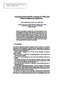
The above de nition showed that a reduced component, connector, or attachments of a component, connector, or attachments may be itself in the case that no its port, role, or attachments has been removed from it, or an empty component, connector, or attachments in the case that all its ports, roles, or attachments have been removed. Figure 3 shows a component incident_mgr, a connector map_request_rpc1, and an attachments rpc_requests as well as their corresponding reduced component, connector, and attachments. The small rectangles represent those ports, roles, or attachments that have been removed from the original component, connector, or attachments. Having the de nitions of a reduced component, connector and attachments, we now de ne the meaning of the word \subset".
incident_mgr call_info_channel
incident_info_request_rpc
incident_update _channel resource_mgr
map_request_rpc1
dispatch_ request_ channel
De nition 3.2 Let P = (Cm ; Cn ; Am ) and P = (Cm ; Cn ; Am ) be architectural descriptions, then: � Cm = fcm1 ; cm2 ; : : : ; cmk g is a \subset" of Cm = fcm1 ; cm2 ; : : : ; cmk g if for i = 1; 2; : : : ; k , cmi is a reduced component of cmi , � Cn = fcn1 ; cn2 ; : : : ; cnk g is a \subset" of Cn = fcn1 ; cn2 ; : : : ; cnk g if for i = 1; 2; : : : ; k , cni is a reduced connector of cni , � Am = fam1 ; am2 ; : : : ; amk g is a \subset" of Am = fam1 ; am2 ; : : : ; amk g if for i = 1; 2; : : : ; k, ami is a reduced attachments of ami , 0
0
0
0
0
0
0
0
0
map_request_rpc2
0
0
0
0
0
dispatcher
map_server
0
0
0
0
0
Figure 1: The architecture of the LAS system.
De nition 3.3 Let P = (Cm ; Cn ; Am ) and P = (Cm ; Cn ; Am ) be architectural descriptions. Then P is a reduced architectural description of P if: (1) Cm is a \subset" of Cm , (2) Cn is a \subset" of Cn , and (3) Am is a \subset" of Am . 0
0
2 can be computed. 3.2
0
0
Intuitively, an architectural slice may be viewed as a subset of the behavior of a software architectural description, similar to the original notion of the traditional static slice. However, while a traditional slice intends to isolate the behavior of a speci ed set of program variables, an architectural slice intends to isolate the behavior of a speci ed set of a component's ports or a connector's roles. Given an architectural description P = (Cm ; Cn ; Am ) of a software system, our goal is to compute a slice Sp = (Cm ; Cn ; Am ) that should be a \subset" of P that preserves partially the semantics of P . To de ne the meanings of the word \subset," we introduce the concept of a reduced component, connector and attachements. 0
0
0
Architectural Slices
0
0
0
Having the de nitions of a reduced architectural description, we de ne some notions about slicing software architectural descriptions. In an architectural description of a software system, a component/connector's interface is de ned to be a set of ports/roles which identify the form of the component/connector interacting with its environments. To understand how a component interacts with the other components or connectors for making changes, a maintainer must examine each port of the component of interest. Moreover, it has been frequently emphasized that connectors are as important as components for architectural design, and a maintainer may also modify a connector during the maintenance. To satisfy these requirements, we de ne a slicing criterion for an architectural description as a set of ports of a component or a set of roles of a connector of interest.
0
De nition 3.1 Let P = (Cm ; Cn ; Am ) be an architectural description and cm 2 Cm , cn 2 Cn , and am 2 Am be a component, connector, and attachments of P respectively: � A reduced component of cm is a component cm that is derived from cm by removing zero, or more ports from cm . � A reduced connector of cn is a connector cn that is derived from cn by removing zero, or more roles from cn . � A reduced attachments of am is an attachments am that is derived from am by removing zero, or more attachments from am .
De nition 3.4 Let P = (Cm ; Cn ; Am ) be an architectural description. A slicing criterion for P is a pair (c; E ) such that: � c 2 Cm and E is a set of ports of c, or � c 2 Cn and E is a set of roles of c.
0
0
Note that the determination of the set E depends on users' interest on what they want to examine. The E may be the set of ports/roles of component/connector c, or just a subset of ports/roles of component/connector c.
0
88
incident_mgr = component { ports : { , incident_info_request, send_incident_info, receive_call_msg } }
incident_mgr = component { ports : { map_request, incident_info_request, send_incident_info, receive_call_msg } } (a)
(b)
map_request_rpc1 = connector { roles : { client_end, serve_end } property : { conn_type : string = RPC; } }
map_request_rpc1 = connector { roles : { , } property : { conn_type : string = RPC; } }
(c)
rpc_requests = attachments : // calls to map server incident_mgr.map_request map_server.request_port1 resource_mgr.map_request map_server.request_port2
(d)
{
rpc_requests = attachments : { // calls to map server
to to to to
map_request_rpc1.client_end; map_request_rpc1.server_end; map_request_rpc2.client_end; map_request_rpc2.server_end;
// incident info from incident_mgr resource_mgr.incident_info_request to incident_info_request_rpc.client_end; incident_mgr.incident_info_request to incident_info_request_rpc.server_end;
// incident info from incident_mgr resource_mgr.incident_info_request to incident_info_request_rpc.client_end; incident_mgr.incident_info_request to incident_info_request_rpc.server_end;
}
} (e)
(f)
Figure 3: A connector, component, and attachments and their corresponding reduced connector, component, and attachments.
De nition 3.5 Let P = (Cm ; Cn ; Am ) be an architectural description. A slice Sp = (Cm ; Cn ; Am ) of P on a given slicing criterion (c; E ) is a reduced architectural description of P which contains only those reduced components, connectors, and attachmentses that might directly or indirectly a�ect the behavior of c through elements in E . 0
0
[6, 9] for programs written in conventional programming languages, is well suited for computing slices of the programs since it provides a powerful framework for dependence analysis. In order to compute a slice of an architectural description, we would like to use a similar representation to explicitly represent dependences in an architectural description. In this section we rst introduce three types of dependences in an architectural description, then present a dependence graph for architectural descriptions.
0
De nition 3.6 Let P = (Cm ; Cn ; Am ) be an architectural description. A forward slice Sf p = (Cm ; Cn ; Am ) of P on a given slicing criterion (c; E ) is a reduced architectural description of P which contains only those reduced components, connectors, and attachmentses that might be directly or indirectly a�ected by the behavior of c through elements in E . 0
0
0
4.1
Traditional dependence analysis has been primarily studied in the context of conventional programming languages. In such languages, dependences are usually de ned between statements or variables. However, in an architectural description language, the basic language elements are topically components and connectors, but neither statements nor variables. Moreover, in an architectural description language, the interactions among components and/or connectors is through their interfaces that are usually de ned to be a set of ports (for components) and a set of roles (for connectors). As a result, it is not enough to de ne dependences just between components and/or connectors in an architectural description. In this paper, we de ne dependences in an architectural description as dependence relationships between ports and/or roles of components and/or connectors. In the following, we present three types of dependences in an architectural description. The rst type of dependence relationship in an architectural description is called component-connector dependences which can be used to represent dependence relationships between a port of a component and a role of a connector in the description. Informally, if there is an information ow from a port of a component to a role of a connector, then there exists a component-
From De nitions 3.5 and 3.6, it is obviously that there is at least one slice or forward slice of an architectural description that is itself, and the architecture represented by Sp or Sf p should be a \subarchitecture" of the architecture represented by P . De ning an architectural slice as a reduced architectural description of the original one is particularly useful for supporting architectural reuse. By using an architectural slicer, a system designer can automatically decompose an existing architecture (in the case that its architectural description is available) into some small architectures each having its own functionality which may be reused in new system designs. Moreover, the view of an architectural slice as a reduced description dose not reduce the use when applied it to architectural understanding because it also contains enough information for a maintainer to facilitate the modi cation. 4
Dependences in Architectural Descriptions
A Dependence Model for Architectural Descriptions
It has been shown that a dependence graph representation such as the program dependence graph (PDG)
89
connector dependence between them. For example, in Figure 2 (a), there is a component-connector dependence between the port receive_incident_info of the component resource_mgr and the role to of the connector incident_update_channel since there is a message ow from the role to to the port receive_incident_info. The second type of dependence relationship in an architectural description is called connector-component dependences which can be used to represent dependence relationships between a role of a connector and a port of a component. Informally, if there is an information
ow from a role of a connector to a port of a component, then there exists a connector-component dependence between them. For example, in Figure 2 (a), there is a connector-component dependence between the role from of the connector call_info_channel and the port send_call_msg of the component call_entry since there is a message ow from the port send_call_msg to the role from. The third type of dependence relationships in an architectural description is called additional dependences which can be used to represent dependence relationships between two ports or roles within a component or connector. Informally, for a component or connector there are additional dependences from each port or role as input to other ports or roles as output. For example, in Figure 2 (a), there is an additional dependence between the roles client_end and server_end of the connector map_request_rpc2 and also an additional dependence between the ports map_request and receive_incident_info of the component resource_msg. 4.2
Software Graph
Architectural
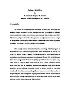
(resource_mgr.receive_incident_info) is a port vertex that represents the port receive_incident_info of the component resource_mgr. Large circles represent connectors in the description, and small circles represent the roles of each connector. Each role vertex has its name described by connector name.role name. For example, rv 7 (incident_info_request_rpc. client_end) is a role vertex that represents the role client_end of the connector incident_info request. The complete description of each vertex is shown in the bottom of the gure. Bold arcs represent component-connector dependence arcs that connect a port of a component to a role of a corresponding connector. Bold dashed arcs represent connector-component dependence arcs that connect a role of a connector and a port of a corresponding component. Thin dashed arcs represent additional dependence arcs that connect two ports or roles within a component or connector. For example, (pv 8; rv 4) and (pv 3; rv 8) are component-connector dependence arcs. (rv 5; pv 9) and (rv 9; pv 2) are connector-component dependence arcs. (rv 2; rv 1) and (rv 6; rv 5), and (pv 2; pv 5) and (pv 7; pv 8) are additional dependence arcs. 5
Computing Architectural Slices
The slicing notions de ned in Section 3 give us only a general view of an architectural slice, and do not tell us how to compute it. In this section we present an algorithm to compute a slice of an architectural description based on its SADG. Our algorithm is a dependence graph based one which contains two phases: (1) Computing a slice Sg over the SADG of an architectural description, and (2) Constructing an architectural slice Sp or Sf p from Sg .
Dependence
To explicitly represent three types of dependences in an architectural description, we de ne a dependence graph named software architectural dependence graph (SADG for short) for architectural descriptions. The SADG of an architectural description is an arc-classi ed digraph whose vertices represent the ports of components and the roles of the connectors in the description, and arcs represent three types of dependence relationships introduced above in the description.
5.1
Computing a Slice over the SADG
Let P = (Cm ; Cn ; Am ) be an architectural description and G = (V; C om; C on; Add) be the SADG of P . To compute a slice over the G, we re ne the slicing notions de ned in Section 3 as follows:
slicing criterion for G is a pair (c; Vc ) such that: (1) c 2 Cm and Vc is a set of port vertices corresponding to the ports of c, or (2) c 2 Cn and Vc is a set of role vertices corresponding to roles of c, � The slice Sg (c; Vc ) of G on a given slicing criterion (c; Vc ) is a subset of vertices of G such that for any vertex v of G, v 2 Sg (c; Vc ) i� there exists a path from v 2 Vc to v in the SADG. � The forward slice Sf g (c; Vc ) of G on a given slicing criterion (c; Vc ) is a subset of vertices of G such that for any vertex v of G, v 2 Sf g (c; Vc ) i� there exists a path from v to v 2 Vc in the SADG. � A
De nition 4.1 The software architectural dependence graph (SADG) of an architectural description P is an arc-classi ed digraph (V; C om; C on; Add), where: � V is the set of vertices that represent each port and role in the P ; � C om is the set of component-connector dependence arcs such that any (u; v) 2 C om i� u is componentconnector dependent on v; � C on is the set of connector-component dependence arcs such that any (u; v) 2 C on i� u is connectorcomponent dependent on v; � Add is the set of additional dependence arcs such that any (u; v) 2 Add i� u is additional dependent on v.
0
0
According to the above descriptions, the computation of a slice or forward slice over the SADG can be solved by using an usual depth- rst or breath- rst graph traversal algorithm to traverse the graph by taking some port/role vertices corresponding to a component/connector of interest as the start point of interest. Figure 4 shows a slice over the SADG with respect to the slicing criterion (resource_mgr; Vc ) such that Vc = fpv 7; pv 8g. The shaded parts of the graph have been removed, i.e., sliced away.
Figure 4 shows the SADG of the architectural description in Figure 2. In the gure, large squares represent components in the description, and small squares represent the ports of each component. Each port vertex has its name described by component name.port name. For example, pv 8 90
call_info_channel
pv1
rv1
incident_mgr
pv5
rv2
pv3 pv4
pv2
call_entry rv8 incident_info_request_rpc rv7 rv3
resource_mgr
rv4
pv7 pv9
call_entry.send_call_msg incident_mgr.map_request incident_mgr.incident_info_request incident_mgr.send_incident_info incident_mgr.receive_call_msg resource_mgr.map_request resource_mgr.incident_info_request resource_mgr.receive_incident_info resource_mgr.send_dispatch_request dispatcher.receive_dispatch_request map_server.request_port1 map_server.request_port2
rv1: rv2: rv3: rv4: rv5: rv6: rv7: rv8: rv9: rv10: rv11: rv12:
call_info_channel.from call_info_channel.to incident_update_channel.from incident_update_channel.to dispatch_request_channel.from dispatch_request_channel.to incident_info_request_rpc.client_end incident_info_request_rpc.server_end map_request_rpc1.client_end map_request_rpc1.server_end map_request_rpc2.client_end map_request_rpc2.server_end
rv9 incident_update_channel
pv8
rv10 rv5
pv1: pv2: pv3: pv4: pv5: pv6: pv7: pv8: pv9: pv10: pv11: pv12:
pv6
map_request_rpc1
rv6 dispatch_request_channel rv11
map_request_rpc2
rv12 pv10
pv11 dispatcher map_server
pv12
Figure 4: The dependence graph of the architectural description in Figure 2 and a slice over it.
5.2
reduced component cn of cn such that cn 2 Sp and cn is not an empty component. { For any connector cn 2 Cn , if there exists no role vertex v such that v 2 Sg and v represents a role of cn , then there exists a unique reduced connector cn of cn such that cn 2 Sp and cn is an empty connector. { The reduced connectors Cn in Sp have the same relative order as the connectors Cn in P. 0
Computing an Architectural Slice
The slice Sg computed above is only a slice over the SADG of an architectural description, which is a set of vertices of the SADG. Since we wish to obtain a slice of an architectural description itself, we should map each element in Sg to the source code of the description. By using the reduced component, connector, and attachments introduced in Section 3, a slice Sp of an architectural description can be constructed in the following three steps. Let P = (Cm ; Cn ; Am ) be an architectural description and G = (V ; C om; C on; Add) be the SADG of P . Step 1: Mapping a port vertex in Sg to its corresponding reduced component:
0
{ For any attachments
am 2 Am , if there exists two vertices such that v1 ; v2 2 Sg and v1 to v2 represents an attachment in am , then there exists a unique reduced attachments am of am such that am 2 Sp and am is not an empty attachments. { For any attachments am 2 Am , if there exists no two vertices such that v1; v2 2 Sg and v1 to v2 represents an attachment in am , then there exists a unique reduced attachments am of am such that am 2 Sp and am is an empty attachments. { The reduced attachmentses Am in Sp have the same relative order as the attachmentses Am in P .
0
0
0
0
Step 3: Reducing an attachments in P to its corresponding reduced attachments:
cm 2 Cm , if there exists a port vertex v such that v 2 Sg and v represents a port of cm , then there exists a unique reduced component cm of cm such that cm 2 Sp and cm is not an empty component. { For any component cm 2 Cm , if there exists no port vertex v such that v 2 Sg and v represents a port of cm , then there exists a unique reduced component cm of cm such that cm 2 Sp and cm is an empty component. { The reduced components Cm in Sp have the same relative order as the components Cm in P. 0
0
0
{ For any component 0
0
0
0
0
0
0
0
0
0
0
0
Step 2: Mapping a role vertex in Sg to its corresponding reduced connector: { For any connector cn 2 Cn , if there exists a port vertex v such that v 2 Sg and v represents a port of cn , then there exists a unique
Figure 2 shows a slice of the ACME description with respect to the slicing criterion (resource_mgr, E) such that E=fincident_info_request, 91
receive_incident_infog is a set of ports of component resource_mgr. The parts contained in rectangles are those that have been removed, i.e., sliced away from the original description. 6
[3] J. Beck and D. Eichmann, \Program and Interface Slicing for Reverse Engineering," Proceeding of the 15th International Conference on Software Engineering, pp.509-518, Baltimore, Maryland, IEEE Computer Society Press, 1993. [4] J. Cheng, \Slicing Concurrent Programs { A GraphTheoretical Approach," Lecture Notes in Computer Science, Vol.749, pp.223-240, Springer-Verlag, 1993. [5] A. De Lucia, A. R. Fasolino, and M. Munro, \Understanding function behaviors through program slicing,"
Concluding Remarks
We introduced a new form of slicing, named architectural slicing to aid architectural understanding and reuse. In contrast to the traditional slicing, Architectural slicing is designed to operate on the architectural description of a software system, rather than the source code of a program. Architectural slicing provides knowledge about the high-level architecture of a software system, rather than the low-level implementation details of a program. In order to compute an architectural slice, we also presented the software architectural dependence graph to explicitly represent various types of dependences in an architectural description of a software system. Based on the graph, we gave a two-phase algorithm to compute an architectural slice. While our initial exploration used ACME as the architectural description language, the concept and approach of architectural slicing are languageindependent. However, the implementation of an architectural slicing tool may di�er from one architecture description language to another because each language has its own structure and syntax which must be handled carefully. In architectural description languages, in addition to provide both a conceptual framework and a concrete syntax for characterizing software architectures, they also provide tools for parsing, displaying, compiling, analyzing, or simulating architectural descriptions written in their associated language. However, existing language environments provide no tools to support architectural understanding, maintenance, testing, and reuse from an engineering viewpoint. We believe that a slicing tool such as an architectural slicer introduced in this paper should be provided by any ADL as an essential means to support these development activities. As future work, we would like to extend our approach presented in this paper to handle other constructs in ACME language such as templates and styles which were not considered here, and also to extend our approach to handle the slicing problem for other architecture description languages such as UniCon and Wright. Moreover, we are also considering to apply the coordination theory [11] to software architecture dependence analysis to identify all primary dependence relationships between components. Finally, to demonstrate the usefulness of our slicing approach, we are implementing a slicer for ACME architectural descriptions to support architectural level understanding and reuse. The next step for us is to perform some experiments to evaluate the usefulness of architectural slicing in practical development of software architectures.
Proceedings of the Fourth Workshop on Program Com-
prehension, Berlin, Germany, March 1996. [6] J.Ferrante, K.J.Ottenstein, and J.D.Warren, \The Program Dependence Graph and Its Use in Optimization," ACM Transaction on Programming Language and Sys-
, Vol.9, No.3, pp.319-349, 1987. [7] K. B. Gallagher and J. R. Lyle, \Using Program Slicing in Software Maintenance," IEEE Transaction on Software Engineering, Vol.17, No.8, pp.751-761, 1991. [8] D. Garlan, R. Monroe, and D. Wile, \ACME: An Architecture Description Interchange Language," Submitted for publication, January 1997. [9] S. Horwitz, T. Reps, and D. Binkley, \Interprocedural Slicing Using Dependence Graphs," ACM Transaction on Programming Language and System, Vol.12, No.1, pp.26-60, 1990. [10] D. C. Luckham, L. M. Augustin, J. J. Kenney, J. Veera, D. Bryan, and W. Mann, \Speci cation Analysis of System Architecture Using Rapide," IEEE Transaction on Software Engineering, Vol.21, No.4, pp.336-355, April 1995. [11] T. W. Malone and K. Crowston, \The Interdisciplinary Study of Coordination," ACM Computing Surveys, Vol.26, No.1, pp.87-119, March 1994. [12] B. Monroe, D. Garlan, and D. Wile, \ACME BNF and Examples," Microsoft Component-Based Software Development Workshop, June 3-5, 1996. [13] J. Q. Ning, A. Engberts, and W. Kozaczynski, \Automated Support for Legacy Code Understanding," Communications of ACM, Vol.37, No.5, pp.50-57, May 1994. [14] K. J. Ottenstein and L. M. Ottenstein, \The Program Dependence Graph in a software Development Environment," ACM Software Engineering Notes, Vol.9, No.3, pp.177-184, 1984. [15] M. Shaw, R. DeLine, D. V. Klein, T. L. Ross, D. M. Young, and G. Zelesnik, \Abstractions for Software Architecture and Tools to Support Them," IEEE Transaction on Software Engineering, Vol.21, No.4, pp.314-335, April 1995. [16] M. Shaw and D. Garlan, \Software Architecture: Perspective on an Emerging Discipline," Prentice Hall, 1996. [17] F. Tip, \A Survey of Program Slicing Techniques," Journal of Programming Languages, Vol.3, No.3, pp.121-189, September, 1995. [18] M. Weiser, \Program Slices: Formal, Psychological, and Practical Investigations of an Automatic Program Abstraction Method," PhD thesis, University of Michigan, Ann Arbor, 1979. [19] J. Zhao, J. Cheng and K. Ushijima, \Static Slicing of Concurrent Object-Oriented Programs," Proc. of the COMPSAC'96, pp.312-320, IEEE Computer Society Press, August 1996. [20] Zhao, J., Cheng, J. and Ushijima, K. : Slicing Concurrent Logic Programs, in T. Ida, A. Ohori and M. Takeichi (Eds.), Second Fuji International Workshop on Functional and Logic Programming, pp.143-162, World Scienti c (1997). tem
References
[1] H. Agrawal, R. Demillo, and E. Spa�ord, \Debugging with Dynamic Slicing and Backtracking," SoftwarePractice and Experience, Vol.23, No.6, pp.589-616, 1993. [2] S. Bates, S. Horwitz, \Incremental Program Testing Using Program Dependence Graphs," Conference Record of the 20th Annual ACM SIGPLAN-SIGACT Sympo-
, pp.384396, Charleston, South California, ACM Press, 1993. sium of Principles of Programming Languages
92