SMALL FOOTPRINT IMPLEMENTATION OF DUAL-MICROPHONE DELAY-AND-SUM. BEAMFORMING FOR IN-CAR SPEECH ENHANCEMENT. Ngoc-Vinh Vu.
SMALL FOOTPRINT IMPLEMENTATION OF DUAL-MICROPHONE DELAY-AND-SUM BEAMFORMING FOR IN-CAR SPEECH ENHANCEMENT Ngoc-Vinh Vu1 , Hua Ye1 , Jim Whittington1 , John Devlin1 , Michael Mason2 1 2
Department of Electronic Engineering, La Trobe University, Melbourne, Australia
Speech and Audio Research Laboratory, Queensland University of Technology, Brisbane, Australia
ABSTRACT For effective speech processing in an automotive environment, speech enhancement is necessary due to significant levels of background noise. In this paper, we present a cost effective small footprint implementation of one particular speech enhancement technique: dual microphone delay-andsum beamforming. In order to save resources, the implementation utilizes the overlapping frame property used in speech processing systems. The implementation also exhibits a simple interconnection structure leading to even greater resource saving. Experiment results show that the proposed design can produce enhanced output very close to that generated by a theoretical (floating-point) model while only requiring a modest hardware resource usage. Index Terms— Dual Microphone, Microphone Array, Speech Enhancement, Noise Reduction, FPGA. 1. INTRODUCTION In the automotive environment, interfering noises such as engine noise, road noise and other traffic noise are a major impediment to acquiring high quality speech signal. This situation makes the operation of hands-free telephones less effective as the noise superimposed with the speech can make the conversation difficult to hear. Devices relying on speech recognition for control also suffer due to the generally poor quality of directly acquired speech. These difficulties can be ameliorated with targeted speech enhancement. In recent years, microphone array-based speech enhancement techniques [1] have received much interest due to the obvious benefits of the use of multiple independent transducers [2]. The microphone array is also attractive as it can be designed to point to a known speaker position, such as, the driver in a car. To realize a speech processing system in an automotive environment, an appropriate hardware platform is required. Cost is a key factor in the highly competitive automotive environment, yet speech processing techniques require considerable digital signal processing (DSP) computations. This re-
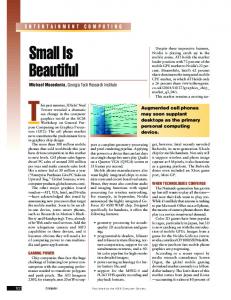
quirement often leads to high resource usage in the hardware implementations and thus makes it difficult to keep cost low. In this paper, we consider the implementation of delayand-sum beamforming (DASB) [3], one of the more widely used multi-channel speech enhancement techniques. By considering the overlapping frame property used in speech processing systems, a small footprint and simple interconnection DASB hardware implementation has been proposed. A design in a FPGA device is also presented as a demonstration platform. To show the advantage of the design to automotive applications, a low-cost automotive device, the Xilinx Spartan-3A DSP 1800 [4], is used. The proposed design can be utilized in a speech recognition system or a general speech enhancement application. The remainder of this paper is organized as follows. Section 2 briefly describes the frequency-domain implementation of DASB. In Section 3, the proposed system using the overlapping frame property is described. Design and experimental results verifying the FPGA design are presented in Section 4 and Section 5. Followed by a conclusion in Section 6. 2. DELAY-AND-SUM BEAMFORMING Beamforming is a method of spatial filtering that differentiates the desired signals from noise and interference according to their locations. The direction where the microphone array is steered is called the look direction. One beamforming technique is the delay-and-sum beamformer which works by compensating signal delay to each microphone appropriately before they are combined using an additive operation. The outcome of this delayed signal summation is a reinforced version of the desired signal and reduced noise due to destructive interference among noises from different channels. As illustrated in Fig. 1, consider a desired signal received by N omni-directional microphones at time t, in which each microphone output is an attenuated and delayed version of the original signal an s(t − τn ) and noise vn given by: xn (t) = an s (t − τn ) + vn (t)
(1)
This work was supported in part by the Australian Cooperative Research Centre for Advanced Automotive Technology (AutoCRC).
978-1-4244-4296-6/10/$25.00 ©2010 IEEE
1482
ICASSP 2010
VRXUFH
]
[��W GPLF
For fixed microphone positions, the array steering vector d and therefore the weighting coefficients wn (ω) will be fixed. Hence, wn (ω) can be pre-computed and saved in read only memory (ROM) to save real-time computation.
GUHI \
GQ
\�W
[Q�W
3. PROPOSED DASB STRUCTURE
[
Fig. 1. Dual-microphone delay-and-sum beamforming
In this section, the redundant parts of the general DASB structure shown in Fig. 2 are identified and some efficient sharing mechanisms are proposed.
In the frequency domain, the array signal model is defined
3.1. Sharing between overlapping frames
as: X (ω) = S (ω) d + V (ω) ,
(2)
where X = [X1 (ω), X2 (ω), · · · , XN (ω)]T , V = [V1 (ω), V2 (ω), · · · , VN (ω)]T . The vector d represents the array steering vector which depends on the actual microphone and source locations. For a source located near the array, the wavefront of the signal impinging on the array should be considered a spherical wave and the source signal is said to be located within the near-field of the array instead of a planar wave commonly assumed for a source located far from the array. In the near field, d is given by [5]: d = [a1 e−jωτ1 , a2 e−jωτ2 , ..., aN e−jωτN ]T an =
(3)
dref dn − dref , τn = dn c
(4)
where dn and dref denote the Euclidian distance between the source and the microphone n, or the reference microphone, respectively, and c is the speed of sound. To recover the desired signal, each microphone output is weighted by frequency domain coefficients wn (ω). The beamformer weights are designed to maintain the beam at the look direction to be constant (e.g. wH d = 1). For a dualmicrophone case, the beamformer output is the sum of each weighted microphone: Y (ω) =
2 �
In speech signal processing, it is common practice to have 50% overlapped frames to avoid missed events occurring near frame boundaries. Normally, when a DFT calculation is performed, the overlapped samples are recomputed on two consecutive frames. However, we observe that half of the computation can be shared between the two neighboring frames resulting in a significant saving in processing effort and time with a novel and simple hardware implementation. Assume that the number of samples in a frame is N and that there is 50% (or N2 ) overlapping between neighboring frames. The DFT computation for the frame can be written as
wn∗ (ω)Xn (ω)
(5)
n=1
The beamformer output Y (ω) is enhanced speech in the frequency domain and ready to be fed to following speech processing blocks. In digital form, the whole process of DASB can be summarized in Fig. 2 where the delay filters are defined by the weighting coefficients wn (ω).
X(k) = ejπk Xhalf
3UH� HPSKDVLV
)UDPLQJ
:LQGRZLQJ
')7
3UH� HPSKDVLV
)UDPLQJ
:LQGRZLQJ
')7
new (k),
(6)
old (k)
and
N
Xhalf (k) =
2 �
x(i)e
−j2πki N
.
(7)
i=0
The calculation of Xhalf old (k) is performed on the N2 overlapped samples that already appeared in the previous frame, while that of Xhalf new (k) is performed on the N2 new samples in the current frame. Recursively, Xhalf new (k) will become Xhalf old (k) in the next frame. The efficient hardware structure using this calculation arrangement is provided in Fig. 3. Both real and imaginary parts are computed in parallel with similar configuration. The speech signal enters the Input Buffer block and is broken up into segments of N2 samples. Every two consecutive segments �
;Q���
5$0�
0$&�� ,QSXW� %XIIHU�
5HDO�')7� &RHII�RXW�
$GG�6XE�
'HOD\� )LOWHU��
&RV� &RVLQH� /78�
RXW FK�
+ Xhalf
where k = 1, 2, · · · , N . The expressions Xhalf Xhalf new (k) are both computed by
;Q��� FK�
old (k)
6LQ�
0$&� �5$0�
&RQY� ,PDJ�')7� &RHII�RXW�
'HOD\� )LOWHU��
Fig. 3. Overlapping DFT hardware structure-Components within the dashed box belong to 1 FPGA MAC primitive
Fig. 2. General diagram of the DASB
1483
5$0�06%�ELW FK� FK�
,QSXW� %XIIHU
')7� 'HOD\�ILOWHU�� 520�
5$0 0$&
&RVLQH
UHDO &RQY
0$&
&RPSOH[� 0XOWLSOLHU�
&KDQQHO��� %XIIHU
$GG� 2XW�
Fig. 5. DASB Delay Filter Diagram
LPDJ
5$0
Fig. 4. Dual channel overlapping DFT hardware structure will form one overlapping frame. Each segment goes through computation in Equation (7). The result of the current segment computation, Xhalf new (k), is then stored in RAM (to be reused as Xhalf old (k) in the next frame computation) at address k. Simultaneously, the Xhalf old (k) is read at the same address k and added or subtracted with Xhalf new (k) to produce DFT of current frame as indicated by Equation (6) (term ejπk only takes on −1 or 1 depending on k). If the above efficient scheme is used, a latency saving of 50% in DFT computation can be achieved but the windowing process must be performed in the frequency domain by circular convolution (Conv block in Fig. 3). This convolution can be simple because widely-used windows, like Hamming or Hann, have only a few (3 for both Hamming and Hann) nonzero values in frequency domain [6]. The Hann window is especially appealing since its nonzero values (−0.25, 0.5, and −0.25) can be processed using a shift register eliminating the need for a multiplier. 3.2. Sharing between two input channels The sharing of the same hardware for both input channels can be achieved with a simple modification to the structure shown in Fig. 3. As all the intermediate computations between segments are stored in RAM, the computation of the second input channel can be added by simply doubling the memory space of the Input Buffer as well as the RAM blocks. When a segment of Channel 1 is finished, the most significant bit of each memory address will be set so that the second half of the memory can be used for Channel 2. The modified calculation system is shown in Fig. 4. Assuming the speech input is a sequence of N real samples, only N2 coefficients are needed. The output of the system will be sequences of N2 DFT coefficients of the first channel followed by an equivalent sequence of the second channel. 3.3. Delay filter In the frequency domain, the process of filtering is simply the multiplication of the DFT coefficients of the input signal with the corresponding delay filter coefficients. Delay filter coefficients are pre-computed and stored in read only memory (ROM). As mentioned previously, the overlapping DFT produces DFT coefficients of the two channels alternatively
1484
in one stream. Thus, to make the structure simple and easy to implement, the coefficients of the two delay filters are stored in one block of ROM; one filter is located in the lower half of address space while the other is located in the upper half. These filter coefficients can be read independently by changing the most significant bit of the ROM address. Fig. 5 shows the diagram of the Delay filter. The product of the filter coefficient (from the lower half of the ROM) and the corresponding DFT coefficient (from the sequence of channel 1) is buffered at the same address of the Channel 1 Buffer block memory. When the DFT coefficients of Channel 2 are calculated and multiplied with filter coefficients from the upper half of the ROM, the product will be added to the Channel 1 delay filter product (already stored in the buffer) to produce the final DASB output.
�
4. FPGA IMPLEMENTATION
The FPGA design has been implemented on a Xilinx Spartan 3A-DSP 1800 development board. This is a low-cost and modest-size FPGA device so that the design’s resource utilization can show the advantages of the proposed small footprint DASB implementation. The development of the FPGA DASB was conducted block by block based on equivalent floating-point MATLAB implementation. Each block was tested after it was completed to ensure correct operation before the next block was developed. The design consists of three main blocks as illustrated in Fig. 6. The first block is the pre-emphasis filter. The common practice for the setting of this pre-emphasis filter is given by y(i) = x(i) − 0.97x(i − 1), where x(i) and y(i) are the ith input and output samples, respectively. Its implementation requires a delay block, a multiplier and an adder. The second block is the dual-channel overlapping frame DFT as presented in Section 3.1 and 3.2 with Hann windowing. The Input Buffer using dual-port BlockRAM configured as circular buffer. Two input channel are multiplexed to be stored to the same circular buffer at lower and upper memory location respectively. The third block is the delay filter as presented in Sec&KDQQHO��� &KDQQHO���
3UH�� (PSKDVLV�
�FK� 2YO')7�
'HOD\� )LOWHU�
Fig. 6. FPGA design diagram of DASB
'$6%�RXW�
0.2 0 −0.2 −0.4 0
4
5
x 10
0.05
0.4 0.2 0 −0.2 0
(a) Channel 1 input data
0 4
5
x 10
−0.05 0
(b) Channel 2 input data
5
4
x 10
(c) FPGA DASB output
Fig. 7. The input data from file set ”AF2 35U P0 C2 M2” of AVICAR database and the output of the Spartan-3A DASB. x 10
−4
Table 1. DASB resources usage on Spartan-3A DSP 1800 device with overlapping DFT and with Xilinx FFT core
1 0 −1 0
2
4
6
8 x 10
4
Fig. 8. Difference between the output of the floating-point MATLAB version and that of the Spartan-3A DASB. tion 3.3 and shown in Fig. 5. Because there is a big gap in time between any two DFT coefficients, only one of the MAC primitive is used to perform the complex multiplication through 4 clock cycles. This provides further saving of hardware resources. The FPGA design of the DASB can easily process dual 16 bits inputs at 16 KHz sample rate in real-time with clock as low as 8.2 MHz. 5. VERIFICATION AND RESOURCES USAGE To verify the FPGA design, Test data signals were feed into the system with the output data passed to a computer for analysis. This output was then compared with that from the floating-point model of the system. To determine relative quantization error range, both the FPGA and the floatingpoint model outputs were converted back into the time domain. The test speech data is from the AVICAR database [7]. Microphone 2 and 6 are chosen as Channel 1 and Channel 2 respectively. Fig. 7 shows an example of the input and output of the system while Fig. 8 presents the difference between the FPGA output and that of the floating-point model using the example inputs in Fig. 7. Here it can be seen that the enhanced output is clean and error is within the range of ±10−4 . This test was replicated with a range of data sets from the AVICAR database with all cases exhibits a consistent error of ±10−4 . For resource usage comparison, A similar design was implemented using a FFT core supplied by Xilinx with Hann windowing in time domain. Table 1 shows the resource usage comparisons of the two implementations. The overlapping DFT design requires only around 2% of Slices and FlipFlop resources, roughly 5% of Multiplier and about 20% of the available BlockRAM. For the similar error range, we save more than 70% of resources compared to the conventional
1485
Resources Slices Flip-flops BRAMs Multiplier
Available 16640 33280 84 84
Overlapping DFT 463 418 18 4
Xilinx FFT 1621 1813 16 22
FFT design with only a slightly greater memory usage. 6. CONCLUSION In this paper, we have presented a small footprint FPGA implementation of the dual-channel DASB for application in incar speech enhancement. By exploiting the overlapping nature of the input frames and other redundancy in the calculation process, the design has achieved a low hardware resource usage on a low-cost FPGA device. Experiment results have shown that the implementation can generate outputs that are very close to the theoretical (floating-point) results and therefore confirmed the effectiveness of the design. 7. REFERENCES [1] J. Beh, R. H. Baran, and H. Ko, “Dual channel based speech enhancement using novelty filter for robust speech recognition in automobile environment,” IEEE Transaction on Consumer Electronics, vol. 52, no. 2, pp. 583–589, May 2006. [2] D. H. Johnson and D. E. Dudgeon, Array Signal Processing: Concepts and Techniques, Simon & Schuster, 1992. [3] G. DeMuth, “Frequency domain beamforming techniques,” in Acoustics, Speech, and Signal Processing, IEEE International Conference on ICASSP ’77., May 1977, vol. 2, pp. 713–715. [4] Xilinx Inc., Xilinx Automotive - flexible solutions beyond silicon, Xilinx Inc., 2007. [5] J. Bitzer and K. U. Simmer, “Superdirective microphone arrays,” in Microphone Arrays, M. S. Brandstein and D. B. Ward, Eds., chapter 2, pp. 19–38. Springer, 2001. [6] F.J. Harris, “On the use of windows for harmonic analysis with the discrete fourier transform,” in Proceedings of the IEEE, Jan. 1978, vol. 66, pp. 51–83. [7] B. Lee, M. Hasegawa-Johnson, C. Goudeseune, S. Kamdar, S. Borys, M. Liu, and T. Huang, “Avicar: Audio-visual speech corpus in a car environment,” in Proc. Conf. Spoken Language, 2004, pp. 2489–2492.