Dec 18, 2007 ... A Distributed Operating System for Sensor Networks by. Jana van Greunen.
Doctor of Philosophy in Engineering – Electrical Engineering and ...
SNSP: a Distributed Operating System for Sensor Networks
Jana Van Greunen
Electrical Engineering and Computer Sciences University of California at Berkeley Technical Report No. UCB/EECS-2007-158 http://www.eecs.berkeley.edu/Pubs/TechRpts/2007/EECS-2007-158.html
December 18, 2007
Copyright © 2007, by the author(s). All rights reserved. Permission to make digital or hard copies of all or part of this work for personal or classroom use is granted without fee provided that copies are not made or distributed for profit or commercial advantage and that copies bear this notice and the full citation on the first page. To copy otherwise, to republish, to post on servers or to redistribute to lists, requires prior specific permission.
Distributed OS for Sensor Networks
by Jana van Greunen B.S. (University of California, Berkeley) 2002 M.S. (University of California, Berkeley) 2004
A dissertation submitted in partial satisfaction of the requirements for the degree of Doctor of Philosophy in Engineering – Electrical Engineering and Computer Sciences in the GRADUATE DIVISION of the UNIVERSITY OF CALIFORNIA, BERKELEY
Committee in charge: Professor Jan Rabaey, Chair Professor Dave Auslander Professor John Wawrzynek Fall 2007
The dissertation of Jana van Greunen is approved:
Chair
Date
Date
Date
University of California, Berkley
Fall 2007
Copyright © 2007, by the author.
Abstract
A Distributed Operating System for Sensor Networks by Jana van Greunen
Doctor of Philosophy in Engineering – Electrical Engineering and Computer Sciences University of California, Berkeley Professor Jan Rabaey, Chair
Sensor networks are an exciting new technology that promise to revolutionize the environment we live in by creating ambient intelligent spaces. In the current software model, applications are statically loaded onto the network at compile time. This means applications cannot react to changes in the underlying network and code reuse is rare because applications are so tightly coupled with hardware. Sensor network deployments suffer from a lack of standard software APIs that allows applications to interact with the network. This dissertation presents SNSP, a distributed service-based operating system for sensor networks. SNSP presents an integrated interface to applications, which abstracts the distributed nature of the underlying network. It enables dynamic application and content management in the sensor network. SNSP’s core consists 1
of seven OS-level services that manage content, discover network resources, monitor resource utilization, dynamically map network applications, provide fault detection and recovery, migrate applications and implement security for the sensor network. Programmers can write services that become a reusable library of SNSP code. The dissertation outlines a programming language and integrated development environment for programmers. Further, the mechanisms for content management and replication and task allocation (mapping) are studied in more detail. Three replication schemes are compared via simulation. Results indicate that the probabilistic scheme has the best performance in terms of cost per data access and increased data availability. Moreover, three task allocation schemes are also compared. The third algorithm, a hybrid genetic search and market bidding protocol, outperforms the other two algorithms. However, due to its twelve times higher computation and 51% higher communication cost the greedy algorithm is preferred. As a proof-of-concept, SNSP is demonstrated on a TelosB and Mica2 (with TinyOS) testbed implementation. The testbed allows applications on different hardware platforms (Mica2 and TelosB) to coexist. Measurements from the testbed indicate that the content management algorithm lowers data access cost and also the time to map a process onto the network.
Jan Rabaey, Dissertation Committee Chair 2
To my mother and Sterling
i
Contents LIST OF FIGURES ........................................................................................................................................... V LIST OF TABLES...........................................................................................................................................VII 1
INTRODUCTION ...................................................................................................................................... 1
1.1 1.2 1.3 2
RELATED WORK .................................................................................................................................... 10
2.1 2.2 2.3 3
SNSP GOALS......................................................................................................6 ASSUMPTIONS.....................................................................................................6 RESEARCH CONTRIBUTIONS ...............................................................................8 SINGLE-NODE OPERATING SYSTEMS ................................................................10 SENSOR NETWORK MIDDLEWARE ....................................................................12 SENSOR NETWORK OPERATING SYSTEMS .........................................................14
DISTRIBUTED OS ARCHITECTURE ............................................................................................... 18
3.1 ABSTRACTIONS .................................................................................................21 3.2 OS-LEVEL SERVICES ..........................................................................................25 3.2.1 Content Management & Replication ..........................................................26 3.2.2 Task Allocation ..........................................................................................26 3.2.3 Resource Discovery & Repository Service ..................................................27 3.2.4 Resource Utilization Monitor.....................................................................27 3.2.5 Application Migration ...............................................................................28 3.2.6 Fault Detection and Recovery ....................................................................30 3.2.7 Security Engine .........................................................................................32 3.3 USER DEFINED SERVICES ...................................................................................32 3.3.1 Initialization ..............................................................................................33 3.3.2 Execution...................................................................................................34 ii
3.3.3 3.3.4 3.3.5 3.3.6 4
Termination ...............................................................................................34 Composition ...............................................................................................34 Performance Metrics ..................................................................................37 Usage Measures .........................................................................................38
PROGRAMMING LANGUAGE AND USER INTERFACE ........................................................ 40
PROGRAMMING MODEL .............................................................................................40 4.1 PROGRAMMING LANGUAGE: SENSC .................................................................41 4.2 .SERV REQUIREMENT SPECIFICATION ................................................................46 4.3 PROGRAMMING UI ...........................................................................................48 4.3.1 Creating an SNSP Application ..................................................................49 4.4 CODING EFFICIENCY GAIN ...............................................................................54 5
FILE ALLOCATION ................................................................................................................................ 55
5.1 PROBLEM FORMULATION .................................................................................56 5.2 RELATED WORK ...............................................................................................59 5.3 LOCATING FILES ...............................................................................................61 5.4 ALGORITHMS TO EVALUATE .............................................................................62 5.4.1 Deterministic, Central Replication Algorithm............................................62 5.4.2 Distributed Algorithm ...............................................................................62 5.4.3 Adaptive Observation-Based Algorithm .....................................................63 5.5 SIMULATION SETUP ..........................................................................................64 5.6 RESULTS............................................................................................................66 5.7 DISCUSSION ......................................................................................................70 6
TASK ALLOCATION ............................................................................................................................. 72
6.1 PROBLEM FORMULATION .................................................................................73 6.1.1 Assumptions ..............................................................................................73 6.2 RELATED WORK ................................................................................................78 6.3 ALLOCATION ALGORITHMS..............................................................................80 6.3.1 Greedy Spanning Tree ...............................................................................80 6.3.2 TASK Algorithm: Local Search for Graph Assignment ..............................83 6.3.3 Genetic Search Algorithm Combined with a Bidding Market Protocol .......86 6.4 SIMULATION SETUP ..........................................................................................90 6.5 RESULTS............................................................................................................94 6.6 DISCUSSION ....................................................................................................104 7
SNSP TINYOS IMPLEMENTATION............................................................................................... 106
7.1 CREATING THE IMPLEMENTATION SCENARIO.................................................106 7.2 TESTBED SETUP ...............................................................................................108 7.2.1 Hardware .................................................................................................108 7.2.2 Location and Connectivity .......................................................................112 7.2.3 Sensors and actuators ..............................................................................112 iii
7.2.4 Content Replication & Capacity...............................................................113 7.2.5 Task Allocation ........................................................................................114 7.3 APPLICATIONS ................................................................................................114 7.3.1 Demand Response and HVAC Control ....................................................115 7.3.2 Motetrack Localization.............................................................................116 7.4 PERSONA ........................................................................................................118 7.5 TESTBED USER INTERFACE ..............................................................................119 7.6 EXPERIMENT ...................................................................................................120 7.6.1 Setup........................................................................................................120 7.6.2 Results .....................................................................................................122 7.7 DISCUSSION ....................................................................................................126 8
CONCLUSION........................................................................................................................................ 127
8.1 8.2
SUMMARY .......................................................................................................127 FUTURE PERSPECTIVES ....................................................................................129
BIBLIOGRAPHY ........................................................................................................................................... 131 APPENDIX I.................................................................................................................................................... 138
HVAC_CONTROL APPLICATION ........................................................................138 HVAC_CONTROL.serv .....................................................................................138 HVAC_CONTROL.h..........................................................................................139 HVAC_CONTROL.c..........................................................................................140 RESULTING TINYOS CODE ......................................................................................143 Module ................................................................................................................143 Configuration ......................................................................................................154 APPENDIX II .................................................................................................................................................. 156
ECLIPSE PLUGIN ......................................................................................................156
iv
List of Figures Figure 1: SNSP architecture layers. ...........................................................................20 Figure 2: SNSP OS-Level Services.............................................................................25 Figure 3: Components of a user-defined service......................................................39 Figure 4: Light control service application structure...............................................41 Figure 6: Comparison of data access cost and replication overhead. ....................67 Figure 7: Comparison of data access cost vs topology and data read/write ratio. ..............................................................................................................................68 Figure 8: Comparison of control message overhead. ..............................................69 Figure 9: Percentage of unavailable data for different schemes and topologies...70 Figure 10: Two task descriptions...............................................................................93 Figure 11: Mapped costs for 3 processes vs. different algorithms including optimal exhaustive search..................................................................................96 Figure 12: Average mapped cost for tasks vs algorithm type. ...............................97 Figure 13: Tasks' choice obtained in they genetic search + Bidding algorithm.....98 Figure 14: Average mapped cost for application sizes vs algorithm type.............99 Figure 15: 3 Histograms of the number of times tasks were mapped n to a processor............................................................................................................100 Figure 16: Mapping complexity vs algorithm type. ..............................................101 Figure 17: Mapping complexity for different task sizes vs algorithm type.........102 Figure 18: Annotated Mica2 mote (taken from [66]) .............................................108 Figure 19: TelosB mote (taken from [67]) ...............................................................110 Figure 20: Testbed with HVAC control and DR that bridges Mica2 and TelosB nodes. .................................................................................................................111 Figure 21: 31-Node testbed, powered via USB & batteries. ..................................112 Figure 22: GUI showing the house, repository services, and applications that are mapped on the network. ..................................................................................120 v
Figure 23: Cost per content access and the proportion of content found replicated on the actual node.............................................................................................123 Figure 24: Time to map a process in milliseconds. ................................................124 Figure 25: Time to map with rf interference...........................................................125 Figure 26: Histograms of the number of times tasks were mapped n to a node for the two network configurations. .....................................................................126 Figure 27: Importing an SNSP project into Eclipse................................................157 Figure 28: Choosing a target to compile. ................................................................158 Figure 29: An open SNSP project, with an open file and a C compilation error. 159 Figure 30: Compiling SNSP code with Eclipse. .....................................................160
vi
List of Tables Table 1: Persona Example. .........................................................................................23 Table 2: Two resource examples...............................................................................24 Table 3: RemoveProcess and Checkpoint objects for application migration.........29 Table 4: Example code for a temperature control application. ...............................45 Table 5: Example of a .serv specification file............................................................48 Table 6: .h file specifying the relevant services, scopes, and persona....................50 Table 7: Blank template C file that the programmer needs to fill in. .....................54 Table 8: FAP Classification ........................................................................................60 Table 9: Number of cluster heads vs number of hops, D........................................66 Table 10: Pseudo code for the greedy algorithm. ....................................................83 Table 11: Pseudo-code for the TASK algorithm.......................................................85 Table 12: Results of mapping two processes onto the regular grid network. ......95 Table 13: Additional communication costs incurred during simulation.............103 Table 14: Number of replicas as a function of time ...............................................122
vii
Chapter 1 Introduction
1 Introduction Widespread sensor network deployment has been hampered by lack of a standard hardware abstraction and matching API for software development. For current sensor network deployments, each deployment is a one-off development effort. The software and hardware are developed together and the sensor network is then deployed in the field. When the application changes or new applications need to be deployed, the nodes are typically retrieved from the field and then new nodes are deployed1. If sensor networks are to become a ubiquitous part of infrastructure in smart spaces, the sensor network platform needs to be more extensible and flexible. Usage scenarios include hospital health monitoring, and energy monitoring (heating, ventilation and air conditioning HVAC) in buildings. In the first scenario, health monitoring, patients and diseases may change every day. The application in a particular room may change 1
For small changes it is possible to reprogram nodes over the air. However, this reprograms the entire image and requires nodes to reboot
1
Chapter 1 Introduction as a new patient enters the room and sensors and actuators may leave and enter the room with a patient. Further, there are some concerns for patient privacy and securing information retained on the sensor nodes. In the second example, applications and requirements may change with regulations or as new companies rent out the buildings. Health and indoor energy monitoring will be used as examples throughout this dissertation to provide illustrative examples of the flexible sensor network abstraction benefits. While there have been successful abstractions for the individual sensor node hardware, for example, IEEE’s sensor interface standard [1] and the instruction set abstraction defined in [2], abstractions for the distributed network are only now starting to emerge. This research presents the Sensor Network Services Platform (SNSP), a distributed operating system abstraction for the sensor network. SNSP’s goal is to allow an application developer to create modular portable code for sensor networks and to avoid building the application from the ground up every time the sensor network changes. Further, SNSP will help harness the potential benefits provided by distributed systems. The advantages of distributed systems include: • Reliability/fault tolerance • Improved resource utilization • Scalability 2
Chapter 1 Introduction SNSP will transform the sensor network into a truly smart environment. It describes a platform based on a set of clean abstractions for users, content, and devices. The platform’s goals are to minimize device configuration and to adapt to different users in the environment. SNSP will be part of the sensor network infrastructure that remains in a building or location even if the people and applications change. As an operating system, SNSP manages the system resources, specifically, it performs resources allocation e.g. memory and computation, allows multiple programs to co-exist, controls input and output devices and manages files or content. Further, SNSP will execute on a physically distributed platform and thus implicitly
supports
communication,
concurrency,
and
synchronization,
providing location transparency. SNSP provides basic, low-level functions for controlling parallel program execution, i.e., functions for loading a parallel program, for starting, halting and resuming. In addition, the notion of users is included in SNSP. As in traditional operating systems, a user’s rights determine which programs, resources, and content they may read, write, and execute. A service-oriented model is chosen for SNSP to separate the function of network services (i.e., what the services do) from their implementation, creating a reusable layer that can be implemented on any hardware platform. There are two kinds of services in SNSP: (1) Operating-system services, and (2) User-defined services. These services play a crucial role in abstracting the specific hardware 3
Chapter 1 Introduction platform from the application, presenting any information required by an application through a unified service API. From the application programmer’s perspective, SNSP presents a familiar sequential programming model. The programming model is supported by predefined services that can be invoked to run in a parallel and distributed fashion. To facilitate programming, SNSP supports a parallel programming language, sensC, and environment abstractions. SensC is syntactically ANSI C with the addition of a few specific features, which are outlined in Chapter 4. At a highlevel, this language supports parallelism up to the granularity of a process. Every application has at least one main process that executes on a single processor, when an application invokes a service, a second “process” is spawned which may be executed simultaneously anywhere in the network (constrained by timing, resources etc.). When application programmers write services, the service/application model provides the way for programmers to explicitly partition the program into parallelizable pieces. SNSP dynamically and automatically finds a place to execute these application pieces.2 This dynamic programming model is a departure from the static one normally used in sensor networks [3]. However, in examining the application space, it is clear that there is use for dynamic migration of programs. Mobile applications were first used in pursuer-evader games [4] where the processing follows the 2
SNSP does not support implicit application partitioning.
4
Chapter 1 Introduction evader through the network, i.e. nodes closest to the evader do the sensing and processing. In this case it is the same application and the same sensing capabilities that are activated in different regions of the network, so it could be programmed in advance. However, both applications and sensor network nodes are becoming more dynamic. Take for example healthcare applications. Change occurs when a new disease is detected, a different sensor is added, a different diagnostic test is devised, or when the patient changes location. All of these changes must be seamlessly incorporated into the system. The distributed operating solution is designed to manage these changes without explicit user interference. SNSP, as an operating system with a built-in set of services, presents a departure from the usual design principles applied in networking. Typically, the network is designed to be ‘dumb’ and intelligence is placed only at the edges. The protocols used to communicate across the network are designed end-to-end [6], in other words, there is end-to-end reliability and end-to-end addressing etc. This traditional design has worked very well with powerful and stationary enddevices. However, with a more heterogeneous and mobile network, there is a push toward breaking end-to-end semantics and embedding more intelligence in the network to relieve the pressure of processing from the devices. Due to the constraints on the sensor nodes, and possible mobility of nodes, SNSP represents a similar break in end-to-end semantics. 5
Chapter 1 Introduction Before describing SNSP in more detail, it is necessary to examine the goals of SNSP and state the underlying assumptions.
1.1
SNSP Goals
First, SNSP abstracts the internals of distributed sensor networks from applications and encourage sensor network deployment. There are three specific goals that SNSP aims to achieve: • Enable applications to execute on different network configurations (agnostic of hardware) which will allow heterogeneous sensor network platforms to interoperate • Shield applications (enable recovery) from node/hardware failures • Optimize application execution by intelligently mapping the application onto the network (may involve run-time migration), which saves energy by reducing communication, increasing reliability and/or performance SNSP is a general platform/middleware that must execute on all sensor network platforms, and therefore may have access to only a few parameters from any given platform. The following assumptions were made:
1.2
Assumptions
• The network contains heterogeneous nodes, which are globally asynchronous and run a kernel of SNSP middleware. 6
Chapter 1 Introduction • SNSP is above the network layer, it cannot change the routing, link, or physical layer protocols. • SNSP is below the application layer and does not know any application semantics. • From the application’s perspective, SNSP exposes geographic addressing, but for each hardware platform this is translated into the local addressing/routing scheme. • SNSP knows/may observe the maximum and average point-to-point throughput (Mb/s) between two neighboring nodes in the network. • There is a standard hardware abstraction for each sensor node which is:
o
MIPS number for CPU
o
Dynamic memory in KB
o
Storage for data in MB
o
Hardware (sensors/actuators)
Because SNSP does not control the underlying communication medium, there is inherent non-determinism and SNSP cannot guarantee communication latency. Moreover, guaranteeing correctness and consistency in an asynchronous system adds a considerable overhead that is not warranted for every sensor network deployment. Therefore, this is not part of the basic SNSP platform. SNSP adopts the BASE semantics: Basically Available, Soft State, and Eventual Consistency, 7
Chapter 1 Introduction which were first introduced in [7] to describe distributed web-caches. BASE semantics are adequate for applications that can tolerate delays on the order of a second.
1.3
Research Contributions
The main contribution of this research is the design of SNSP. SNSP is a fullfledged operating system with memory management, location transparency, and resource allocation. SNSP enables the creation of applications that can be mapped onto the network at runtime and allows the programmer to build up a library of reusable sensor network services. Further, the research focuses on two aspects of SNSP, file allocation and tasks allocation. These were chosen because they have a significant impact on sensor network performance and they have not been adequately addressed in existing work. The contributions of the thesis are: • Identified and designed the basic set of services for a distributed operating system • Devised a programming model and user-interface that allows users to create reusable libraries of code • Developed a novel file allocation algorithm • Evaluated the performance of three file allocation algorithms via simulation 8
Chapter 1 Introduction • Developed two novel task allocation algorithms • Evaluated the performance of three task allocation algorithms via simulation • Proof of concept implementation of SNSP on top of a TinyOS sensor testbed with select performance measurements The rest of the thesis is organized as follows: Chapter 2 describes related work in sensor network operating systems and middleware. Chapter 3 outlines the architecture of SNSP, namely the abstractions and services that it provides programmers. The user interface and programming model is described in Chapter 4, followed by a problem formulation and detailed analysis of file allocation algorithms in Chapter 5. Chapter 6 presents a similar analysis of the task allocation problem. Chapter 7 describes SNSP implementation on a 30-node testbed, running TinyOS as the underlying operating system.
9
Chapter 2 Related Work
2 Related Work The related work on sensor network platforms can be divided into three categories: 1) The single-node operating system, which focused mainly on small footprint and code size. 2) Sensor network middleware, which attempts to abstract commonly used functionality and standardize it. 3) Fully-fledged distributed operating systems for sensor networks. The distributed operating systems take the goals of middleware platforms a step further by not only providing a set of common functionality, but also controlling and optimizing the execution of applications on the network. They provide real-time coordination and control of the sensor network. Research in the three categories is outlined below.
2.1
Single-Node Operating Systems
The most popular single-node operating system is TinyOS [8]. TinyOS consists of a set of software modules in the NesC language [9]. Components are not divided 10
Chapter 2 Related Work into user and kernel modes and there is no memory protection. TinyOS does not support preemption. The code is statically linked at compile time. Version two of TinyOS introduces some lower-level improvements to abstract the platform from the hardware. TinyOS is very widely used in sensor network test-beds and in published research results. Thus, it is an ideal platform to develop software on that other groups will use or compare results with. TinyOS was selected as the basis for the implementation platform as described in Chapter 7. BTNodes [10] were developed by ETH Zurich. These nodes have their own hardware platform and operating system, called BTNut. BTNut is a multithreaded preemptive operating system written in C. It also has a TCP/IP stack built in. BTNut is the closest to other commercial RTOS systems, but it has not had the same traction in the academic setting as TinyOS. MANTIS [11] is an open source, multi-threaded operating system written in C for wireless sensor networking platforms. It has automatic preemptive time slicing for fast prototyping and an energy-efficient scheduler for duty-cycle sleeping of sensor node. Another interesting sensor network operating system is SOS [12], which supports dynamic application modules. Application modules can be loaded or unloaded at run time. Modules send messages and communicate with the kernel via a system jump table, but can also register function entry points for other modules to call. SOS is a more extensible platform
11
Chapter 2 Related Work than TinyOS, but it is not as widely adopted, and it supports fewer hardware platforms.
2.2
Sensor Network Middleware
Research on sensor network middleware aims to abstract common functionality and present it in reusable form. There are four main approaches to designing middleware for sensor networks: 1) Database, 2) Publish-subscribe 3) Services, 4) Mobile agents/clustering. The database involves abstracting the sensor network as a database and then allowing a user to write SQL-like queries to extract sensor data from the network. TinyDB [13], Cougar [14], and SINA [15] are the most well known of these approaches. The research focus here is on efficient query processing and routing. [16] writes wrappers for the underlying sensor network (single-node operating system) and then use an XML framework for syntactic description and then SQL for data manipulation. The second approach, publish-subscribe, disconnects the data production from its consumption. A set of data producers publishes their data in the network. Interested parties can then subscribe to the data. [17] presents a set of operators that interested parties can use to describe patterns of data that they are interested in. Typically somewhat complex time stamping is needed to get any useful data. Mires Middleware [18] is another publish-subscribe mechanism. Initially sensor nodes publish the types of data that they can provide. Client applications then 12
Chapter 2 Related Work select the data that they care about and subscribe to it. Only after receiving a subscription will sensor nodes publish their data. There is not much data available on how expensive the subscription language is, or what overhead it adds to the network. DSWare [19] is not a traditional publish subscribe mechanism, but it does cache data in the network and it provides a language for other nodes to subscribe to events. The Milan platform [20] is an example of a service-based approach. Applications wishing to execute represent their requirements to Milan through specialized graphs that incorporate state-based changes in application needs. The graphs contain variables and QoS for each variable. Milan knows the level of QoS that data from each sensor or set of sensors can provide for each variable. For a given application, Milan can send and receive data from these variables. There is not much data on how the matching between applications and resources is done. [21] defines a set of roles in the sensor network that have rules associated with them. An application must choose one of these roles to play and the network knows how to load balance the application based on the role it is playing. Sensorware [22] defines a set of base services that the network must provide to an application. However, it does not define the mechanisms by which the network must deliver these services. These services are as follows: • Communications Protocol Stacks • Power Management 13
Chapter 2 Related Work • User Interaction • Network Synchronization • Query Processing • Configuration (e.g. health status and maintenance) • Fault Tolerance • Security/Authentication The last type of middleware is agent-based. In Agilla [23], each application is a mobile agent that decides independently when and where to migrate. Agilla is based on the mate platform [24]. Nodes have Linda-like [25] tuple spaces and an acquaintance list that allows them to find a place to migrate. The shortcoming of this approach is that there is no attempt to achieve network optimality or analysis of what happens when there is inter-agent interaction.
2.3
Sensor Network Operating Systems
The first two operating systems presented both rely on applications that are comprised of identical code fragments, in other words, applications that can be decomposed into smaller, identical sub-problems. In [26] the main abstraction is that of Microcells. Microcells begin their life-cycle as inactive software components and are activated by stimuli in the environment, as well as by events in the computing system. The programmer must specify how a microcell reacts to stimuli. Once a microcell is activated, stimuli can cause it to perform self14
Chapter 2 Related Work replication, migration, or grouping. For example, growth may be controlled to reach the required computing capacity or geographic coverage for different functions performed in the vicinity of an event. The distributed operating system determines where and when microcells execute. The system implements its own microcells, which implement fundamental activities in the infrastructure, such as information storage. [27] outlines Bertha, an operating system that can accommodate 11 process fragments at a time. Bertha manages processor startup, memory, access to hardware peripherals, communication with neighboring Pushpins, and provides a mechanism for installing, executing, and passing neighbors code and data to execute. The main drawback of these two approaches is that they only fit applications which can be broken down into small homogenous pieces. Kaizen [28] focuses on a resource usage description and sandboxing strategy. CPU, memory, radio, and sensor/actuator usage contracts are outlined, in addition to methods to stop processes from consuming more resources than specified in their contracts. However, they do not address the optimal placement for processes or other services that may aid process execution. The Eyes project [29] aims to achieve small code size and to solve the limited available energy problem by defining clear stop and start portions in the code after which the processor can be put to sleep. Nodes are able to make resources requests via remote procedure calls to their directly connected neighbors when 15
Chapter 2 Related Work they do not have enough energy or processing power to fulfill a certain task. EYES also defines a distributed services layer which provides a lookup service and an information service. The lookup service supports mobility, instantiation and reconfiguration. The information service collects network data. The drawback of eyes is that nodes can only make local resource requests and they do not support a full mapping of applications onto the network. [30] defines a service manager that is responsible for receiving and accomplishing service requests. There are two primitive request types: query and order, and two complex types: conditional and repetitive. The service manager uses the distributed service directory (DSD) to find a pairing for the request. Their DSD uses S-CAN [31], a distributed hashtable developed for content-addressable networks. The service manager and DSD is similar to the mapper and repository service presented in this research, but the services presented here can deal with a richer set of applications. The last two distributed systems are the most similar to SNSP in their goals and generality. The [32] design separates the core OS kernel, OS services, and distributed applications. The core kernel and the OS services control the behavior of a single node, while applications implement the distributed system behavior of the sensor network. Applications consist of processing elements connected via arcs. As SNSP does via equivalence classes, they allow for runtime reconfiguration of the model, including changing interconnections and 16
Chapter 2 Related Work replacement of processing elements (PEs). Communicating PEs can be located on the same, or different physical nodes. There is not much data on how Omni achieves placement of applications, a core aspect of the system that this research focuses on. Last, Magnet OS [33] provides a single system image of a unified Java virtual machine to applications. It partitions applications components statically along object interfaces. Magnet OS then finds an initial placement for these components on the network. MagnetOS uses the Java RMI interface for remote object invocation during run-time. During execution, two services adjust task placement to optimize communication cost. NetPull migrates components one hop at a time in the direction of greatest communication. NetCenter migrates components to the host that a given object communicates with the most. Magnet OS conceptually has the same goals and achieves them in a similar way as SNSP. However, it has the overhead of a full Java implementation in addition to not being able to reuse or share Java classes among applications at runtime. Note, classes are shared at compile time. SNSP’s application construction is specifically designed so that applications can use existing components on the network.
17
Chapter 3 Distributed OS Architecture
3 Distributed OS Architecture SNSP is a distributed operating system. SNSP code executes directly on the nodes in the sensor network. Each node runs its own native operating system and SNSP code runs as middle-ware on each node. SNSP is designed to run on a heterogeneous sensor network; a network comprised of nodes with different capabilities e.g. battery-powered nodes, constantly powered nodes and perhaps different bandwidth availability. It can also operate on a homogenous network, and a totally asymmetric network, where the base-station does all processing and the other nodes simply collect data. As an operating system, SNSP manages system resources, performing resource allocation e.g. memory and computation, allowing multiple programs to co-exist, controlling input and output devices and managing files/content. Due to the nature of sensor networks, SNSP will execute on a physically distributed, heterogeneous
platform
and
thus
implicitly 18
supports
communication,
Chapter 3 Distributed OS Architecture concurrency, and synchronization, providing location transparency. As in traditional operating systems, a user’s rights determine which programs, resources, and content they may read, write, and execute. There are several ways to design the architecture of a distributed operating system. The most common approach is the micro-kernel approach. In this approach, each component that comprises the distributed computing system runs the same kernel of code that takes care of basic services. A more flexible approach was desired for sensor networks as the entire computing system is not designed at one time, and parts may be incrementally added. Therefore, SNSP is actually middleware that runs on top of a basic operating system for each node. When SNSP layer is ported to a new operating system, it must be able to interface directly with that operating system and also be able to translate the routing and addressing. SNSP is not only a distributed operating system for sensor networks, it also provides a uniform abstraction for applications running on it. This abstraction encompasses a common terminology to refer to applications, resources and people in the environment. An abstraction set was included in SNSP because sensor networks are intimately tied to the environment, and being able to compactly present aspects of the environment is essential to the success of reusable and general sensor network software.
19
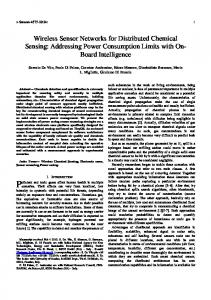
Chapter 3 Distributed OS Architecture A service-oriented model was chosen for SNSP to separate the content of network services from their implementation. These services form a reusable layer that can be implemented and shared across any hardware platform. The core layer of SNSP is comprised of services that handle concurrency, file allocation, security and resources. These services are a standard part of SNSP and are described in detail below. However, SNSP is also extensible via user-defined services. User defined service are meant to encapsulate higher-layer functionality so that they can be re-used across different sensor networks. A specific API is provided that allows users to write these modular components (or applications). The API is outlined in this section and further elaborated on in Chapter 4. Figure 1 shows a graphical representation of SNSP architecture. Application User-Services SNSP Core (OS-level Services) Native OS (Sensor Network Nodes)
Figure 1: SNSP architecture layers.
As an example scenario, healthcare monitoring will be used throughout this chapter. For healthcare monitoring the sensor network is installed in a hospital. Patients stay in the hospital for an average of three days. During the course of their stay, different sensor nodes are attached to their bodies. These nodes monitor different vital statistics, e.g. blood oxygenation, blood pressure, heart 20
Chapter 3 Distributed OS Architecture rate, blood sugar level, breathing speed, stress levels etc. There is also a stationary sensor network in the hospital. These nodes may monitor the environmental conditions in the room (temperature, humidity), or be attached to larger machines, or to a system that alerts doctors and nurses when a patient needs them. As patients enter and leave the hospital, the applications executing change in accordance with the diseases being monitored. For example, the sensor network may be monitoring a patient for seizures. This application could combine heart-rate monitoring with stress level monitoring and it may also involve administering of certain anti-seizure drugs. Further, the application may require fine sampling of data from the sensors and thus it may be better to execute the control function locally, rather than route a large amount of data to a central base-station in the hospital. In addition, the data that the sensor network collects about the person must be interpreted and stored correctly. SNSP abstractions are presented below, followed by a description of OS and user-level services.
3.1
Abstractions
There are three main abstractions in SNSP environment: Personae, Content, and Resources. These abstractions were first presented in [34]. First, a persona represents a single person, groups of people, or organizations (e.g. nurses organization). In addition, a persona with sufficient privilege may set rules of 21
Chapter 3 Distributed OS Architecture operation for the environment (e.g. only nurses may have access to the medicine cabinet). A persona may be present or absent in a certain environment, but can still affect its operation even if they are not present. The run-time system uses personae rules to interpret, act on, and resolves conflicts between multiple users. A persona consists of the following components: • Permissions are user's access rights to devices, content, services, and applications. For example, permissions may limit a user's ability to control devices in the home such as lights. Further, permissions specify a persona’s category or priority (e.g. ability to override another persona). Persona categories are described in more detail in the equivalence section • Properties contain information that describe user(s), e.g. age or gender. Properties may help the system to detect and distinguish users from each other. The persona also has an authenticate function. • Preferences contain information regarding user actions or default system configuration. Preferences may also be used to enforce certain user behavior. For example, in health monitoring it is important to determine whether a person has taken the correct medicine each day and to encourage them if they have not done so. In order to make personae more concrete, an example persona, describing a homeowner is shown below: 22
Chapter 3 Distributed OS Architecture Class: Persona Name: Homeowner Permissions: r,w,x for content, programs, devices Properties: Sex: Female, Age: 60 Preferences: isPresent(location); Table 1: Persona Example.
Second, the concept of content abstracts information that services and application can manipulate. Content may represent a range of data: media streams, sensor readings (light, temperature, motion, identification), security information, energy monitoring results, health data etc. Separating content from the sensors that generate it, and actuators that consume it, allows the system to cache and replicate content to provide fault tolerance. In SNSP, all content has unique identifiers, a size field and properties. In the health monitoring example, content is very important. The content must be stored to provide doctors with accurate medical data to look for potential problems as well as a record of patient care especially of medicines taken. It is important that this content is not lost in the sensor network. Content must also be kept private. Last, resources uniformly abstract physical resources in the environment. Resources are typically categorized by functionality (e.g. sensor –“current temperature” content source, routing node – connection from A to B, transcoder – conversion Celsius to Fahrenheit). Resources do not have an invocation/execution 23
Chapter 3 Distributed OS Architecture API. For each resource there is a corresponding service that indicates how to utilize it. There are two main types of resources: The first is a specific physical resource, for example a sensor or actuator. The second is computation and connectivity resources. The physical resources have an input and an output domain. The input/output domains may be physical (lumens, heat to measure temperature) or they may be numerical, ie reading from an on/off switch. A resource also has a description of how much connectivity, computation power and memory it can provide. An example of a heater is shown below followed by an example computation resource that has the heater attached to it:
Class: Resource Name: Heater Location: LivingRoom Properties: Manufacturer: GE Power: 1000W Input Domain: numerical (10 bit) Output Domain: physical (heat) Class: Resource Name: Computation Location: LivingRoom Reliability: 99.9% CPU: 1 MIPS CPU Used: 0 Dutycycle: 10%;1 second RAM: 10KB Memory: 100MB Current used: 10MB Connectivity: 10kbit/s Hardware: Heater Table 2: Two resource examples.
24
Chapter 3 Distributed OS Architecture
3.2
OS-level Services
OS services are the lowest level services that keep track of the system at the device and connectivity level. OS services play several roles in the system, they: • Resolve resource allocation conflicts between applications or persona. • Support discovery of resources, persona, and content in the system • Track of the utilization and availability of resources, persona, and content. • Replicate code and content in the sensor network to maximize availability and minimize data access costs • Map applications onto the nodes at runtime • Detect application failure and take corrective action • Manage security and trust for the system resources, persona, and content These functions have been divided into seven services shown in the figure below.
OS-Level Services Content management & replication
Application Migration
Task Allocation (Mapper)
Resource
discovery& repository
Fault detection & recovery
Figure 2: SNSP OS-Level Services.
25
Resource utilization monitor
Security engine
Chapter 3 Distributed OS Architecture 3.2.1 Content Management & Replication The content management and replication service distributes content throughout the sensor network. The underlying challenge providing this service is to optimize content placement for availability and minimize communication (both access and update) costs. This problem is known as the file allocation problem (FAP) and has been extensively studied for traditional distributed databases. The FAP may be based on static allocation or dynamic allocation; the access patterns may be deterministic, probabilistic or unknown. All versions of the FAP are NP complete [35]. This thesis evaluates two well-known file allocation algorithms in addition to developing its own. A formal problem statement as well as simulation results are presented in Chapter 5.
3.2.2 Task Allocation This problem is closely related to the file allocation problem; in fact, the file allocation problem can be turned into a task allocation problem. The tasks comprising the application are the files. The application specifies an access pattern between the files. The tasks have additional constraints: namely, computation, dynamic memory, hardware, and location and bandwidth constraints. The optimal task allocation has been shown to be NP complete [36]. However, there is a large body of research on heuristic task allocation algorithms. This thesis presents and compares three heuristic task allocation
26
Chapter 3 Distributed OS Architecture algorithms in the sensor network setting. The formal problem statement, with detailed constraints, is outlined in Chapter 6.
3.2.3 Resource Discovery & Repository Service In SNSP we have chosen to do reactive resource discovery. The system does not proactively send out discovery messages, instead, nodes send out a register message when they join the distributed system. The register message contains information about the resources present on the node, as well as a content and/or service code that may be present on the node. This information is wrapped up as repository content then stored in the network. The distributed content management and replication service decides where to store this repository content. Further, the repository contents have soft-state. Thus, nodes must periodically re-announce their presence, otherwise it is assumed that they have died or left the network. Querying the repository service accesses the repository contents. The repository service provides the following types of information: • Available content, personae, and resources • Available services in the network and their API’s
3.2.4 Resource Utilization Monitor The resource utilization service gives information about resources that are used by applications and services currently executed in the network, in addition to the 27
Chapter 3 Distributed OS Architecture unallocated resources remaining in the sensor network. The mapper and content management service use the resource utilization service to determine what is available for allocation. The resource utilization service receives the resource record from nodes that send their periodic registration updates (as part of resource discovery). This provides the service with information about currently available resources. The resource utilization service also works with the mapping service to keep track of resources that have been allocated to processes, but that have not yet been “consumed”. To facilitate this, SNSP has a coupon system. A coupon is placed on each resource that the mapper decides to allocate to a process. Once the process has been initialized, it “consumes” the coupon and the nodes’ resource state gets updated. The resource utilization service also keeps track of coupons issued to resources to assure that a resource is not over-provisioned. Resource utilization records are distributed and managed in the same way that content is.
3.2.5 Application Migration To enable applications to migrate from one node to another node, the application’s state must be captured. This is known as checkpointing an application. When the mapper wants to relocate an application, it will request that the application checkpoints itself. Note, both applications and services may
28
Chapter 3 Distributed OS Architecture migrate from node-to-node, thus the application/service will be referred to as a remote process. Checkpointing involves the creating of a checkpoint object. The checkpoint object stores the remote process’s current execution position, any local content that may have been generated as part of the process state, the services that the process are currently using (including specific queries to these services that the process has made and not yet received responses to), and services/applications that have sent queries to the process (there are referred to as waiting services). This state is captured in the RemoteProcess object. The interfaces for the RemoteProcess and checkpoint objects are given in Table 3.
Class: RemoteProcess ID: XXX Location: XXX start(void* args); stop(void* args); suspend(); resume(location); servicesUsed(name, loc, queries); waitingServices (name, loc, queries); stateContent(content); processDescription(ast); //abstract syntax tree rep of proc code processStackPointer(void *); Class: Checkpoint ProcessID: commit(); //update complete initialize(processID); recover(); //returns last committed checkpoint recoverLast(); //returns last data update(void* args); //updates part of a remote process e.g. stack ptr Table 3: RemoveProcess and Checkpoint objects for application migration.
29
Chapter 3 Distributed OS Architecture 3.2.6 Fault Detection and Recovery The advantage of distributed systems is that it allows applications to be more tolerant of partial failures (there is redundant hardware for applications to recover from failure or faults). Due to homogeneity of different platforms and various energy constraints in sensor networks, it is not practical to require a universal fault tolerance/recovery standard for sensor networks. However, SNSP supports three loosely defined levels of fault tolerance: recoverable processes, fault detecting processes and none. Recoverable processes have the maximal support from the underlying network to both detect and recover from faults. Fault detecting processes will simply be restarted when a fault is detected, but are not guaranteed to preserve state. Last, there are processes for which the system guarantees no tolerance at all. The first step of fault tolerance is fault detection. Due to energy constraints, SNSP does not, by default, actively monitor for faults in the network. Instead, it relies on a combination of information from the application and the resource discovery/utilization services. First, SNSP provides applications with a mechanism to signify a fault in one of its sub-processes (i.e. a service that it has invoked) Given the application composition (the task graph described in Chapter 4), a component that is using a service can naturally detect if a fault has occurred (e.g. data is not arriving according to specification or an incorrect service was
30
Chapter 3 Distributed OS Architecture invoked). This mechanism can also be used to validate semantics of requests in the system. The second method of fault detection is relying on information from the resource discovery and utilization services. Through these services, SNSP keeps track of resource states in the network. A variety of faults, i.e. nodes dying, nodes not executing a process, etc., can be detected by combining information from these two built-in services. Once a fault has been detected, the system must recover from the fault. From the fault detection information, SNSP will know what process failed. If that process is still executing, it will immediately be terminated. If the program is a recoverable process, SNSP must resume the process instead of simply re-starting it. Recoverable processes must create checkpoint objects (described in the application migration service). The processes determine how often to update their checkpoint objects. The checkpoint objects are stored and replicated by the content management service to ensure that an accessible copy exists in the network. Once SNSP has located the process’s checkpoint, the process is remapped onto the network. The re-mapped process starts executing again from its last checkpoint. However, the other tasks in the application may receive old or duplicate information from the re-mapped process, which may lead to race conditions. In order to avoid this, SNSP notifies all tasks belonging to an application when the process is re31
Chapter 3 Distributed OS Architecture mapped and provides them with the checkpoint sequence number. Further, it is recommended that communicating tasks include sequence numbers in the packets they exchange. For processes that are fault detecting, no checkpoint object exists, so the process is simply remapped and restarted by the mapper service.
3.2.7 Security Engine As in [34], the security in SNSP is based on persona and their access permissions. Personae control access to content and are able to set permissions dictating what can instantiate processes on the sensor network. A full-blown implementation of this security is left as future work for SNSP. There has been other work done on authentication, encryption and privacy in sensor networks, [37], [38], and [39] serve as excellent staring points for a secure system.
3.3
User defined services
The service description can be used to determine how a service should be replaced on failure and to check compatibility if a user wants to use or extend a service. The service description includes a high-level description of what the service does, and other properties that are useful in defining the service. The service API consists of several components; a brief description of these components is given below, followed by more detailed subsections.
32
Chapter 3 Distributed OS Architecture Services have three stages of operation: initialization, execution, and termination. Each of these phases consists of a usage API and a high-level functional representation. When services are invoked, their initialization code is executed. During the execution stage applications and/or other services may query the executing service for content, or actuation of a resource. Queries and actuations are equivalent and handled through the same API. In addition to the three stages, services have structural, usage, and performance properties. Structural properties pertain to the service composition. Usage and performance properties are collected and stored in the repository service whenever the service is executing. These properties are expounded on and illustrated below.
3.3.1 Initialization Initialization is an important part of setting up an application or preparing the system to record data. Initialization may contain several functions, e.g. turning resources on, calibrating sensors etc. Every function has an identifier and an API for calling the function. In addition to the functional API, there is also a description of what each function does (computationally), called the behavioral task. In the health monitoring example initialization might involve calibrating a particular sensor e.g. oxygenation or heart monitoring sensor to work with a particular patient.
33
Chapter 3 Distributed OS Architecture 3.3.2 Execution The execution stage also consists of two main components: the service invocation API, and the service behavioral task description (computation description of each function in the API). The service invocation API refers to a set of queries that you can make to the service once it is running. It consists of a set of functions with typed arguments and return values. The basic functions through which a service module interacts with its environment is depicted in Figure 5 and an example service is given in Table 4 and Appendix I.
3.3.3 Termination Similar to initialization, termination may consist of several functions, which are represented as an API and a behavioral task component. In the healthmonitoring example, termination may happen when the patient is discharged from the hospital. It could involve recording all patient data in a permanent database and then erasing it from the sensor nodes.
3.3.4 Composition These properties specify how a service is “put together”. They are listed below: • Resources This component specifies the type of sensor/actuator that is required and also other resources (ADC, bus etc.) that will be used during service execution. Further, computation and connectivity are also resources. Resources may be specified as a particular entity, or as an equivalence class. 34
Chapter 3 Distributed OS Architecture Equivalence classes are explained in Section 4.2. In health monitoring, a resource may be the sensor required to monitor a particular patient’s condition. A temperature sensor may be needed to monitor the patient’s temperature. Temperature sensor is the equivalence group, and specific incarnations of it may be an oral temperature sensor or an inner-ear sensor etc. • Service Structure A service can be either simple or compound. Simple services are self-contained and do not invoke any other services during execution. In contrast, compound services do invoke other services. If a service if compound, the service structure must also contain a list of the sub-services that are invoked during execution. These sub-services may be specified according to their equivalence class. A compound service’s access restrictions must be a superset of all the access restrictions of its sub-services. For example, a seizure monitoring service may use inputs from the heart-rate sensor, the skin-moisture sensor, whereas a simple patient-temperature monitoring service may only use a temperature sensor. Note: these two services may themselves be part of a larger patient wellness application that is launched on patient arrival. • Service Scope defines the scope, location and time, that a service can operate in. This is not the instantiation scope that is passed to the service as an invocation parameter. Rather, it is the scope that it is possible for the service to 35
Chapter 3 Distributed OS Architecture operate at all. The service may be limited in location because certain services are provided by individual pieces of hardware. This hardware may be restricted in space and also in the time of usage. Also for certain services, it makes no sense to measure during certain times, e.g. nocturnal activity during the day or photovoltaic cell power generation in the night. • Service Content Services generate results when they are executed. These results are classified as “content”. Content may be stored in the network and used for later reference or consumed immediately. Caching may be used so the service does not have to execute each time it is invoked, rather, it may return already stored content. Further, a personae who instantiates a service may also impose privacy restrictions on the content (e.g. can it be shared with other personae or other services). For example, content may be a history of the patient’s heart rate over 1 second intervals. • Security & Access All services in the sensor network are controlled (and instantiated) by a persona or a group of personae. Access to service information (read/write) is determined by these personae. This component grants or restricts the access of certain personae to the service description. As an example, medical information may be accessed by the patient’s direct family only, and not by other visitors. Further, the restriction is specified on a component-by-component level, it may differ across individual parts of the service description. Another important security constraint is instantiation 36
Chapter 3 Distributed OS Architecture rights (execute). Personae can be denied access to instantiate a service in the network. Read/write and execute privileges are specified independently of each other. For compound services (calls other services to complete its result), the service’s security must be at least as strict as its sub-classes. The security and access components are limited only to the service description. We assume that data encryption and other authentication is done by the service during runtime.
3.3.5 Performance Metrics These are the performance metrics that the underlying network must have for the service to complete successfully. The performance of a service can be broken down into the following components. Each of these can be specified as a max or min value: • Delay • Synchronization (order on events & to reference) • Accuracy • Reliability (exactly one delivery, at most one delivery, best effort … etc) • Throughput (network bandwidth) If an application requests a performance level that a service cannot meet, or the service itself requests a performance level that the underlying network cannot meet, SNSP will simply send the application an error message. 37
Chapter 3 Distributed OS Architecture 3.3.6 Usage Measures This section keeps statistics of the number of times a service is accessed. Also, statistics are kept just for each incarnation of the service definition, i.e. if two service definitions differ in any component, they must have different usage measures. The usage measures are of the following: • Access Count indicates how many times this service definition is read, written, or executed. This is for unique accesses by different services/personae. • Alive Count of how many alive/executing copies there are in the network. The repository makes a distinction between simply accessing the service definition, and accessing it to execute/instantiate it. • Validity Time period specifying how long the current copy is valid for, e.g. 1 hour, 2 days. This time period specifies the refresh rate, entities (that are executing, or using the service definition) must check with the repository to see if the service has been updated. This requirement allows programmers to keep the code in the sensor network up to date and allow updates to propagate through the network in a timely manner. Note: when nothing changes, the “check-back” is only a control message exchange (check version #), so its overhead is relatively small.
38
Chapter 3 Distributed OS Architecture A summary of the different parts that comprise a user-defined service is given below:
Control flow Invocation Execution Termination
Composition Resources Structure Scope Content Security
Figure 3: Components of a user-defined service.
39
Performance & Usage Access Aliveness Validity
Chapter 4 Programming Language and User Interface
4 Programming Language and User Interface This chapter presents a programming model for SNSP. The programming language for SNSP is ANSI C, which it is very standard and well known. However, ANSI C is augmented with other descriptors (stored in separate files), which specify constraints and auxiliary services used by applications. The chapter concludes by presenting an Eclipse [40] integrated development environment (IDE) that can be used to write applications for SNSP. A sample application is presented in Appendix I and SNSP Eclipse IDE is presented in Appendix II.
Programming model In SNSP’s programming model, an application is a task that has inputs, outputs and a computational part. Any of these portions may be provided by other tasks/services. Given this structure, the application can conceptually be seen as a 40
Chapter 4 Programming Language and User Interface hierarchical combination of tasks. The diagram below shows an example lightcontrol application structure in which the application uses the person locating service (which gives the locations of people in the building), the sunlight metering service (which determines if sunlight is providing sufficient luminance), and the lightSwitch service (which actuates a given set of lights). In turn, the person locating service uses a combination of RFID reading services and services exposing data from motion sensors. The arrows between tasks in the figure signify communication between the different processes. Services can be considered a library of applications that conform to SNSP’s service API presented in Chapter 3.
Light cntl
People ID service RFID service
Sunlight service
Light switch service
Motion service
Figure 4: Light control service application structure.
4.1
Programming language: sensC
The programming language sensC is ANSI C [41] with a few extensions. C was chosen because of its widespread use in the embedded world. The language 41
Chapter 4 Programming Language and User Interface consists of two types of files: the first type is standard C (.c and .h files with a few reserved keywords and functions) the second type is service specification files, which end with a .serv extension. First, the .c and .h files define the functionality of the sensC program. A sensC program is divided into three sections: the initialization, execution and termination sections. The sections may also contain standard C functions. By default, these functions are public and may be called directly by other sensC modules in the sensor network. sensC supports timers and non-preemptive event queues for scheduling computation.
Figure 5: SNSP and sensC module.
Further, sensC modules interact with SNSP via a set of functions. Figure 5 ....interaction.
illustrates the function calls between SNSP core, an application represented as a sensC module, and a third-party service that the application is using. The four functions are listed below: 42
Chapter 4 Programming Language and User Interface
• requestService() This function is called by a sensC module when it wants to use a service deployed on the sensor network. The first three parameters of the function are: (1) the requested service, which may be a user-defined service, or an essential service such as localization or the repository service, (2) scope, location and time to execute the service, and (3) the argument to the service. The argument to the service is a section, followed by the desired function within that section, for example execution:invoke(). Optional parameters are authentication, encryption, and request performance constraints, e.g. delay, reliability, accuracy etc. •
invokeService() This function is called by SNSP to notify a service that it
has been requested. A sensC module that behaves like a service needs to implement this invokeService function. The parameters are the same as those of the requestService() function. • serviceRespond() This function is called by a sensC service module when it responds, has results to return, to another module that requested the service. The required parameters are the request ID, the return scope, the return service, and a result value field. Note that the value field is a C struct, with a header that indicates the total payload length. The payload contains result entries, which contain the type and length of the result, as well as the actual result value. Optional parameters are authentication and encryption. 43
Chapter 4 Programming Language and User Interface •
serviceResult() This function is called by SNSP to return the result of a
request to the original sensC module. The parameters are the same as serviceRespond(). •
register() This function is periodically called by every sensC service module. It registers the service as belonging to the network and gives a complete service description (i.e. its interface as a list of functions with the formats of their arguments and results). See section 3.3 for more information on the service description.
When a user wants to write an application, they are presented with a blank template file containing the four service calls. The template file is further explained in section 4.3 as a part of SNSP IDE. Table 4 shows an example of a thermostat application. Some code has been left out to simplify the application. In the example code the application initializes some default values on startup. SNSP (not shown in the user-code) will also query the repository service (CRS) to find out where the heater, temperature sensing and user-desired temperature sensing services are located. This information is stored in the availService array (the exact format of this is specified in Section 4.4.). Then, in the execution section, the application keeps requesting the temperature and a user temperature until it has received them, after which a control function is executed to turn the heater on or off. 44
Chapter 4 Programming Language and User Interface
boolean scope int boolean scope int scope servDat
hasTemp tempScope temperature; hasUserTemp; userTempScope userTemperature; heatScope; availServices[SERVICES_USED];
Invocation: invoke(){ hasUserTemp = hasTemp = false; } Execution: executeControl (){ if(!hasTemp && availServices[temp].exist){ tempID = requestService(TEMP, tempScope); return; } if(!hasUserTemp && availServices[userTemp].exist){ userTempID = requestService(USERTEMP, userTempScope); return; } if (availServices[heater].exist) { if(temperature < userTemperature) requestService(HEATER, heatScope, ON); else requestService(HEATER, heatScope, OFF); } } } terminate(){} serviceResult(id, value){ switch(id){ case tempID: temperature = value->payload; break; case userTempID: userTemperature = value->payload; break; } } Table 4: Example code for a temperature control application.
45
Chapter 4 Programming Language and User Interface
4.2
.serv Requirement Specification
The .serv file consists of two segments. The first segment details information about the sensC module’s runtime requirements. This will be used by SNSP to dynamically deploy the module on the sensor network. These requirements are: • Data in-flow rate (shaped by leaky bucket) • Data out-flow rate (shaped by a leaky bucket) • Memory requirements such as dynamic memory and intermediate storage on a node • Resource requirements (i.e hardware that must be co-located on the node) • Fault tolerance requirements (see section 3.2.6 on fault detection and recovery) The second segment contained in a .serv file specifies information about the other services or modules that the sensC module will invoke during execution. In order to make the sensC module more applicable to general sensor networks, services are specified via equivalence classes. Equivalence classes specify a set of properties that a service must have to be considered an equivalent candidate. In order to evaluate different equivalent services, the properties may be specified with an evaluation function that assigns a grade to the service depending on its exact value of its property. For example, there may be two temperature services in the network; one may have an accuracy of ±1°C and the other ±5°C. These 46
Chapter 4 Programming Language and User Interface services are equivalent, but the first is more valuable to a module that has high accuracy requirements. Equivalence classes allow a service to be substituted for another when the original one is not present in a sensor network. For large equivalent sets, a decision tree structure can be used to efficiently represent an equivalence class. The decision tree not only encodes all the properties required of the service, but also an order in which to evaluate them. Given a good choice of variable ordering, [42] has shown that decision trees are both a compact way to store evaluation functions and an efficient mechanism to check whether a service matches the criteria.
In the current SNSP
implementation equivalence classes are specified as priority lists. Table 5 shows an example .serv file. The top half of the file specifies the constraints such as data in-flow-and-outflow rates. The second half of the file lists equivalent services. The line “Service:x” denotes the start of a new equivalent group. For service 2 there are two equivalent services: Cricket [43] and Motetrack [44] localization. Cricket is an acoustic localization service whereas Motetrack uses RF and is not as accurate. The accuracy of both localization services is known (represented in the functional API). The algorithm prefers Cricket to Motetrack if it is available in the network. Also, if QueryPeriod is set to 0, then it is the responsibility of the application to query the service during execution. If it is non-zero, SNSP will periodically query the service for results. 47
Chapter 4 Programming Language and User Interface ModuleName:example DataIn:10,5 DataOut:8,2 Memory: 2 Processing: 10 ResourceReq:ServiceName FaultTolerance:detection Service:0 Name:TEMPERATURE Scope:KITCHEN QueryPeriod:5 Name:TEMPERATURE Scope:LIVINGROOM QueryPeriod:8
/* units are kb/s */ /* units are kbytes */ /* Can also be left blank */ /* recoverable, detection, nothing */
/* query once every 5 seconds */
Service:1 Name:HUMIDITY Scope:SP_SCOPE_ALL QueryPeriod:10 Service:2 Name:CRICKET_LOCALIZATION Scope: SP_SCOPE_ALL QueryPeriod:0 Name:MOTETRACK_LOCALIZATION Scope: SP_SCOPE_ALL QueryPeriod:0 Table 5: Example of a .serv specification file.
4.3
Programming UI
SNSP is not just a distributed operating system for sensor networks. It is also a platform that allows users to write applications for sensor networks. This is known as an integrated development environment (IDE), which is a PC-side tool that allows users to create and compile SNSP applications. IDEs normally consist of a source code editor, and a compiler/interpreter. 48
Chapter 4 Programming Language and User Interface Eclipse was chosen as the IDE for SNSP. [40] Eclipse started as an open-source Java tool to build Java IDE’s, but now consists of an open source community whose projects are focused on building an open development platform comprised of extensible frameworks, tools and runtimes for building, deploying and managing software across the lifecycle. The Eclipse platform is extensible via plug-ins. Plug-ins are “pluggable components,” which conform to Eclipse's plug-in contract. These plugins work seamlessly with the core part of Eclipse during runtime. They may do something simple like adding a single button that displays a message to a user, or soething complex like adding support for compiling another language. There is a Tinyos plugin [45] that allows users to write and compile TinyOS code within the Eclipse IDE. SNSP Eclipse plugin is fully described in Appendix II.
4.3.1 Creating an SNSP Application The first step in creating an SNSP application is defining all the services that will be used during the application’s execution. The services as well as the scope are defined in the .serv file. See Section 4.2 for an example. Next, these specifications must be reflected in the C files. First, the services and locations used are defined in numerical format in the .h file. An example .h file is given in Table 6 below.
49
Chapter 4 Programming Language and User Interface /* * Place the names of locations and services here * Note, the spelling & capitalization must be the same as that * used in the .serv file */ enum { /* eg location: * KITCHEN = 1, * LIVINGROOM = 2, * DININGROOM = 3, */ /* eg Service names * TEMPERATURE = 9, * HVAC = 14, * COMFORT = 15, * DESIRED_TEMP = 16, * HVAC_CONTROL = 19, */ /* eg persona * OWNER = 22, */ BRIDGE = 17, OFF = 2, ON = 1, SENSOR = 10, ACTUATOR = 20, CONTROL_TRIES = 3, //#times try to respond before timeout REPLY_TRIES = 3, ACTIVATE = 2, DEACTIVATE = 3, }; typedef struct serviceUsage { uint8_t name; scope_t scope; int platform; uint16_t ticksToQuery; int invocationID; int exists; } Table 6: .h file specifying the relevant services, scopes, and persona.
50
Chapter 4 Programming Language and User Interface Table 6 also shows the serviceUsage structure, which is of particular interest. SNSP will create a serviceUsage array the size of all the services used. During execution, SNSP will periodically query the repository service to determine which of the equivalent services exist in the network. It will populate the serviceUsage array with information about the top equivalent service that it finds in the repository. If an application wants to query this service, it can find the service name and scope in the service usage array at the index specified in the .serv file. When the application programmer starts a new SNSP project, the main functionality of the application gets placed in the C file that is created. The blank C file contains a number of functions that need to be filled in. Table 7 shows the blank C file. Most of the functions have comments describing the calling context and arguments. These functions are essentially those described in Section 4.1 by the sensC module interaction. An example of a completed C file and the resulting compiled tinyOS code is given in Appendix I. The example shows a thermostat application.
#include "table.h" /* * Place all the variables to store results from services used * eg uint16_t sensorSample1 * uint16_t sensorSample2 */ /*
51
Chapter 4 Programming Language and User Interface * during execution these will be filled in and updated * with the name & scope of the equivalent service that * exists in the network - see bottom of file for * a definition of the struct */ serviceUsage services[NUM_SERVICES_USED]; /* * fill in, it will be called on initialization */ void invoke() { } /* * fill this in - it will be called every second * Use it to process results, query more services, actuate etc. */ void executeControl() { } /* * Fill this in if you want other components to use this service * it will be called on the service in response to a * requestService call and it should call serviceRespond * to pass the result back to the callee * @param fn function that will be called * @param args - arguments to the function * @param arg_len length of the arguments (not null terminated) * @param id -identifies the request, should be passed back to * serviceRespond * *@return int return 0 if the service successfully invoked, * 1 otherwise */ int invokeService(uint8_t fn, char *args, uint16_t arg_len, uint8_t id) { } /* * * * * * * *
Fill in to process the result of a service query/invoke service @param fn - function name that was called @param payload - results @param payload_len - length of results (they are not null terminated) @param id - request id that was returned in requestService
52
Chapter 4 Programming Language and User Interface */ void serviceResult(uint8_t fn, char *payload, uint16_t payload_len, uint8_t id) { } /* called when the mapper is wrapping up the service * clean up any last minute state */ void terminate () { } /*------------------STUBS-----------------------* * Leave at the bottom of the file - will be filled in by SNSP */ /* * This is a stub will send a service query * @param servNum is the equivalence class specified in * the .serv file * @param servName is the class that was found in the network * (that is equivalent from - serviceUseage * services[NUM_SERVICES_USED];) * @param fn is the function name that will be called * @param args is a void pointer to arguments to the service * @param argLen is the length of args (not null terminated) * * @return int returns the id that will be used in * serviceResult to pass result back */ int requestService(uint8_t servNum, uint8_t servName, uint8_t fn, char *args, uint16_t argLen) { } /* * This is a stub * @param fn - function that was called * @param results - pointer to results * @param * * @return 0 if successful 1 if not */ int serviceRespond(uint8_t fn, char *results, uint16_t resLen, uint8_t id) { }
53
Chapter 4 Programming Language and User Interface Table 7: Blank template C file that the programmer needs to fill in.
4.4
Coding Efficiency Gain
The programming language and UI were developed to make writing sensor network applications easier for programmers. One way to measure the gain in efficiency is to compare the number of code lines saved. In the example given in Appendix I, the C code is 146 lines long. The resulting TinyOS code is 711 lines for the HVAC_CONTROLM.nc module (which contains the application code) plus an additional 2109 lines for the supporting SNSP TinysOS code. That is a savings of 1932%. As the program gets more complex, the application’s C part will get longer and the supporting SNSP code will be amortized over many modules. However, there is still a significant savings of 2674 lines of code.
54
Chapter 5 File Allocation
5 File Allocation The underlying challenge in providing this service is to optimize content placement for availability and to minimize communication (both access and update costs). This problem is known as the file allocation problem (FAP) and has been extensively studied for traditional distributed databases. The FAP may be based on static allocation, which means that the files are allocated once ahead of time, or dynamic allocation. Further, the file access patterns may be deterministic, probabilistic or unknown. All versions of the FAP are NP complete. This research focuses on dynamic file allocation with unknown file access patterns. Further, the work places more importance on reducing the communication cost to access a file, and aims to increase file availability. The chapter starts by outlining the formal file allocation problem. Next related work and the process of locating files are addressed, followed by the presentation of 55
Chapter 5 File Allocation three heuristic algorithms: A deterministic central replication algorithm, a distributed probabilistic replication algorithm, and a learning-based algorithm. These algorithms are compared via simulation to a control case with no replication.
5.1
Problem Formulation
A version of the static FAP, similar to that in [35] is formulated below. Given: • n nodes • m files • lj is the length of the jth file for 0 < j ≤ m • bi is the available memory of the ith node for 0 < i ≤ n • cj is the storage cost per unit at the jth node • CAi is the capacity of the ith link And traffic vectors where the incoming traffic arrives with a poisson distribution: •
uij is the query traffic originating from node i for file j
• vij is the update traffic originating at node i for file j • u’ij is the return traffic to node i from queries for file j • v’ij is the return traffic to node i from updates of file j
56
Chapter 5 File Allocation Chu [35] formulated the file allocation problem as a zero-one integerprogramming problem. The variable Xij is the indicator function that the jth file is stored on the ith node.
Xij =
1 if jth file is stored on the ith node 0 otherwise
$ ! # ! "
(1)
Storage cost is given by:
Zstore = cTXl Where c = (c1, c2, …,
cn)T
and
l = (l1, l2,…,
lm)T
(2)
If file j is stored at! qj different nodes in the network, where n
qj = ! Xij
(3)
i =1
The total traffic generated in the network is now: n
m
Zcomm = !! [(uij + uij' )(1 " Xij )+ (vij + vij' )(qj " Xij )]
(4)
i =1 j =1
The objective of the file allocation problem is to minimize the storage cost (eqn 2) and the total communication cost (eqn 4) of transporting data through the network. For SNSP, storage capacity and availability constraints can be formulated as follows: 57
Chapter 5 File Allocation
Ccap =
#X L " b ij j
i
for 1 " i " n
(5)
j
Analytical expressions for availability are hard to obtain, so an approximation, given in![46] is used. This approximation is explained below. First, we define rik to be the probability that two nodes i, and k successfully communicate. In order to derive the analytical expression, we assume rjk is independent rmn for all m not equal to j and all n not equal to k. This can be calculated for each pair of nodes if the routing and node availability is known. This probability includes the probability that node k is available. (In the simulation the availability to access a file at location k from location j is not explicitly calculated; only the availability of the node k is taken into account).The availability aij of file j accessed by node i is n $ ' aij = &1" # (1" rikXkj )) % k=1 (
(6)
Let Wij be the total traffic demand at node i for file j. Wij = uij + u’ij + vij + v’ij. The
!
weights indicate the relative popularity of files. The traffic-weighted availability for each file is given by: n
j Cavail =! i =1
Wij aij n
!W
ij
i =1
58
(7)
Chapter 5 File Allocation The optimization problem given a target t, availability constraint a and variable
λ, is: an allocation F(X) that minimizes F(X)= Zstore + λZcomm (eqn 2, 4) subject to Ccap C javail > a
5.2
(eqn 5)
for 0 < j ≤ m (eqn 7)
Related Work
Content replication algorithms (also known as file allocation problems) were studied extensively with the rise of networked computer systems in the late 60’s and 70’s. The optimal solution is NP complete. Techniques for file allocation include branch and bound, randomization, predictive Markov techniques, genetic algorithms and other heuristics. [47] gives a good overview of these difference techniques. Further, the solution techniques employed depend on the assumptions that are made and the different constraints that are considered. As shown in Table 8, in one variant of the content replication problem the input pattern is not known in advance but the algorithm must react to file requests as they arrive. This class of problem is known as online problems. Typically, competitive algorithms are used to solve/analyze online problems. Competitive algorithms have the property that their performance on any sequence of requests is within a constant factor of the performance ‘of any other algorithm (including the optimal) on the same sequence. See [48] for more details. This work will 59
Chapter 5 File Allocation compare algorithms that do not know the access pattern in advance to each other. Input
Pre-determined Probabilistic Unkown
Solution type
Static (files are allocated once) – optimal or heuristic Dynamic (files migrate during process) – optimal or heuristic
Structure
Single File (assume files are independent) Multiple Files (for high-throughput case, files may content with each other w.r.t. queueing delay) Files as program data
Metrics
Minimize execution cost Minimize communication cost Maximize availability Maximize throughput Minimize access delay Minimize file transfer times
Table 8: FAP Classification
In the sensor network setting there has not been task allocation work per se, but there has been work on the related problem of data storage and retrieval. Solutions include modeling the sensor network as a database [13], adapting hash tables from content addressable networks with geographically distributed hash tables [49]. This is used to find and store data and sensor network fusion, where a sensor needs to figure out where to send its data when queried [50]. This work has focused on making data retrieval more reliable and cheaper, but it has been 60
Chapter 5 File Allocation mostly focused on collecting data through a central point, and has not allowed for data replication in the network.
5.3
Locating Files
Existing content replication algorithms do not address locating the content. In the worst case, nodes need to flood the network to locate information. In order to avoid flooding, an indexing system is used. Indices are placed at warehouse nodes, which have higher availability and storage space than their peers. Warehouse nodes are selected via a clustering algorithm in a d-hop neighborhood. This work uses the clustering scheme presented in [51], which selects as cluster heads nodes within D hops having the highest id. This work uses a combination of the node’s availability and storage as criteria for cluster head selection. The cost of maintaining the content indices is added as overhead cost. Note, the cost of accessing a warehouse is on average be D/2, the average distance a node is from its cluster head. Thus it is beneficial to reduce D to lower the cost. However, as D is decreased, the total number of cluster heads increases, which increases the cost to write a new location to all warehouses.
61
Chapter 5 File Allocation
5.4
Algorithms to Evaluate
5.4.1 Deterministic, Central Replication Algorithm This algorithm was adapted from [52]. The algorithm is O(logn) competitive. For each data item, the algorithm maintains a list of L read requests and also a tree structure T of pointers to all replicated data. d is the size of the data. The algorithm executes as follows: • On read request r, the algorithm finds sphere S with radius k that contains d reads • If no copy of a file exists within a sphere of radius λk of the r, the file is replicated to the node with the highest availability in the sphere, and it is added to T • Read requests from nodes in S are deleted from L • After d writes, all copies in T are deleted and the one on the node with the highest availability is kept
5.4.2 Distributed Algorithm This algorithm was adapted from [53] to improve the availability of the data. It is O(log2n/log2d) competitive (where d is the size of the data and n is the number of nodes). A tree Tp is kept for replicas of item p: • On a read request from r, insert the node with the highest availability in r’s one-hop neighborhood in Tp with probability 1/d 62
Chapter 5 File Allocation • On a write request from w, with probability 1/(sqrt(3)*d), delete all nodes in Tp, except for the one with the highest availability and add w to T
5.4.3 Adaptive Observation-Based Algorithm This algorithm uses an observation period during which nodes observe the number of read/write requests. Replication decisions are made after this period. Initial step: • Observe 100 accesses of a data item p, keep record of their location and whether it was a read/write. Reallocation: • After r reads • Create k = floor(r/20) replicas of the data item • Use k-means to divide the data requesters into k clusters and store one data item on the node within each cluster with highest availability. Now that there are replicas in the network, writes can either come directly from a node (meaning that the replica was the closest copy to be written) or they can happen when data is written through for consistency. Refinement steps (on each node that has a copy of p): • Observe 100 accesses of the data item. • Accesses are either reads r, direct writes wd, or update writes wu. 63
Chapter 5 File Allocation • If wu > r + wd remove the replica from the node • If r > wd create k = floor(r/20) replicas and use k-means to distribute the replicas onto a node with the highest availability in each cluster.
5.5
Simulation Setup
I used the discrete event simulator Omnet++ [54] with the Mobility Framework (MF) [55] extension. MF was developed at TU-Berlin and provides a good model of the WSN physical and MAC layers. The simulation consists of 1000 nodes randomly placed in a 2000m x 2000m square. The nodes have a radio range of approximately 150m. The network’s heterogeneity is also varied, with a heterogeneous network consisting of nodes with 3 amounts of storage: 10k, 50k, and 200k. Nodes with a large amount of storage are available 99.9% of the time, nodes with a medium amount of storage have a 95% availability and the smallest nodes have a 80% availability. In the homogenous network, nodes have 2 different amounts of storage, 50k and 100k, and they are available at rates 97% and 94% respectively. Availability refers to the percentage of the time a node will be awake and respond to incoming packets. All nodes are unavailable for an exponentially distributed time with the same mean, so a higher availability means lower chance of becoming unavailable. The relative times are calculated so that nodes are probabilistically awake for the percentage specified by their availability. 64
Chapter 5 File Allocation When a node is available, it wakes up every 0.25 seconds, and decides with probability 0.1 to read or write a randomly selected piece of data. Each simulation consisted on average of 39,000 queries. All data items are the same size (100), but they have different read to write ratios of 1:1, 3:1, 15:1 and 100:1. Cluster head election occurred at the start of the simulation and the cluster heads did not change during the simulation. For the lower layers, a standard fading channel was used with an Aloha MAC [56] (both of these are provided by the mobility framework). At the network layer, geographic routing and addressing is used. The following assumptions are made: • Nodes know the id’s of data items they want to access • ID’s are much smaller in length than the data item • Data items are indivisible and the original copy cannot be deleted or migrated to another node • There are no concurrent read/writes (relatively few events in WSN) • Nodes have a finite amount of storage • Node failures/deaths are modeled as an independent binomial process, independent of other nodes. • Nodes also fail temporarily (which corresponds to temporary downtime e.g. sleeping to conserve power).
65
Chapter 5 File Allocation • Nodes know their own availability, i.e. the proportion of time that they are in functioning condition.
5.6
Results
The first experiments examined the tradeoff between number of cluster heads, their availability, and the number of hops, D. Results in Table 9 show a summary of the number of cluster heads vs number of hops, D. The results were similar across both topologies. All cluster heads were the highest availability nodes, even with D of 2. Further, there is clearly a tradeoff between the number of hops, D, a cluster head is away from a node and the number of cluster heads to keep synchronized when a data item’s location changes. Due to the relatively small change in number of clusters from 3 to 8 hops, D was chosen to be 3 for the remainder of the simulations. D 2 3 4 8
# Cluster Heads 10 6 5 3
Availability 99.9 99.9 99.9 99.9
Table 9: Number of cluster heads vs number of hops, D.
Figure 6 shows the total cost (the number of hops data was transported) per data access for each of the schemes. The solid portion of the bar represents the direct cost of the operation. For example, for a write operation that represents the cost to transport the data from the writing node to the closest replica in the network. 66
Chapter 5 File Allocation The top portion of the bar is overhead to keep replicas consistent. Considering the data access cost, the adaptive algorithm performs the best, followed by the distributed algorithm, the deterministic algorithm and last the control algorithm. However, considering total cost, the distributed algorithm outperforms the adaptive algorithm. This is because the distributed algorithm saves on replication cost by replicating to the nodes (or nodes very close to them) that make the queries. While the adaptive algorithm has a better placement of replicas (because its access cost is lower), it incurs additional cost because it locates replicas independent of queries. The overhead of the deterministic algorithm makes it more costly than the control algorithm.
Figure 6: Comparison of data access cost and replication overhead.
Figure 7 shows the cost breakdown for the distributed and adaptive schemes by topology and data read/write ratio. Topology 1 is the heterogeneous topology and topology 2 is the homogeneous topology. There is not much difference 67
Chapter 5 File Allocation between the two topologies. On average, across all read/write ratio entries for the same scheme, the two topologies differ by, 0.3 hops or roughly 4%. The read/write ratio has a bigger impact on cost. In both schemes the same pattern is visible; the overhead is much larger for data with lower read/write ratios. This overhead shrinks to almost nothing for data with a read/write ratio of 100 in the distributed algorithm. Intuitively, this is because the placement of the data does not incur an overhead, and even though there are many replicas, writes are so infrequent that they add little to the total cost. Thus, these schemes provide more benefit for data that is read much more frequently than it is written.
Figure 7: Comparison of data access cost vs topology and data read/write ratio.
68
Chapter 5 File Allocation The previous graphs showed only the cost of moving data around the network. Figure 8 shows the control message overhead. The distributed algorithm has the lowest control message overhead followed by the deterministic and the adaptive algorithms. The data read/write ratio does not have a large impact on overhead cost, because the overhead is dominated by the cost of finding an item; there is not much difference between finding a location to read from or one to write to. Moreover, this overhead is not as significant as the data cost shown in Figures 6 and 7. If data ids are a 10th the size of the data payload, then these numbers should be divided by 10 to scale them to those in Figure 6. On average, the distributed algorithm would cost 0.27 hops more, the deterministic algorithm would cost 0.34 more and the adaptive algorithm would cost 0.4 hops more. The control overhead becomes even more significant if the ratio between the data payload size and the data id size becomes larger.
Figure 8: Comparison of control message overhead.
69
Chapter 5 File Allocation In addition to the cost of the replication scheme, data availability is also an important concern in SNSP. Figure 9 shows the percentage availability of data for all schemes and topologies (the 1, 2 on the x axis indicates topology). Topology does have an impact on availability; the homogeneous topology has a higher availability than the heterogeneous topology. The distributed replication improved reliability the most with a 33% improvement for topology 1 and a 51% improvement for topology 2.
Figure 9: Percentage of unavailable data for different schemes and topologies.
5.7
Discussion
This chapter presented a formal problem definition of content replication and management. The problem was then investigated in the context of sensor networks. Specifically, as part of SNSP, a distributed operating system, which dynamically maps data and programs onto the sensor network. Out of the three algorithms that were empirically compared, the distributed replication scheme 70
Chapter 5 File Allocation performed the best with the lowest total cost and the highest availability. The adaptive algorithm developed for SNSP performed the best when considering only data access cost, indicating that it had better placement than the other algorithms. However, it also had higher control message overhead. The simulations showed that all replications schemes provided more benefit for data with more frequent reads than writes. Finally, the simulations showed that although the replications schemes improved data availability, the sensor network topology has an impact on data availability. The homogenous network had roughly 2% more availability than the heterogeneous network. From a practical perspective, the distributed algorithm performed the best, it is very simple to implement and has low overhead.
71
Chapter 6 Task Allocation
6 Task Allocation This chapter formulates the task allocation problem for SNSP. The task mapper takes SNSP task description (including a list of sub-tasks that can be further partitioned or assigned to individual sensor nodes) as input. In a sensor network the mapping must happen in a decentralized way. The problem is formally stated in this chapter, followed by related work. The optimal solution is NP complete, and therefore the goal of this chapter is to evaluate heuristic file allocation solutions for SNSP. In order to facilitate this, three algorithms are outlined in this chapter and then compared via simulation. The algorithms can also implement incremental mapping of processes. Incremental mapping is when a task (that is part of a process) is already running in the network, it is shared between the two processes, instead of mapping two copies of the task on the network. The results compare both incremental and non-incremental approach.
72
Chapter 6 Task Allocation The algorithms are distributed. The solution can be structured so that each task has an independent mapping agent or each resource has a mapping agent. The task-mapping agent evaluates the best mapping and then takes care of obtaining the resource for the task and any contention that may result. The resource agent receives bids to obtain its resource and performs allocations to the highest bidders. The algorithms chosen are aimed to reduce the communication overhead between tasks and to increase information availability.
6.1
Problem Formulation
The mapper’s function is to allocate resources to processes so that they can execute on the sensor network.
6.1.1 Assumptions • Nodes know the IDs of data items they want to access • Data id’s may be arbitrary in length, so long as they are prefix-free • Nodes have a finite amount of storage available for data items • Node failures/deaths are modeled as an independent binomial process, whereby each node fails independently of others. • Nodes know their own availability, i.e. the proportion of time that they are in functioning condition.
73
Chapter 6 Task Allocation In the mapping problem, we assume that we are given the following information: Given n nodes and m processes for 0 < j ≤ m and 0 < i ≤ n • hj is the RAM requirement of the jth process • gi is the computation requirement of the jth process • oi is the hardware requirement (e.g. sensors) of the jth process • tj is the location requirement (e.g. kitchen, house) for the jth process • ei is the available RAM of the ith node • qi is the available CPU of the ith node • ci is the cost to execute a process at the ith node • ui is the hardware on the ith node • pi is the location of the ith node • sik is the bandwidth between nodes i and k for 0