California Institute of Technology. Pasadena, CA 91125. AbstractâThis paper addresses the issue of soft errors in quasi delay-insensitive (QDI) FPGA.
Soft-error Mitigation for Asynchronous FPGAs Wonjin Jang, Alain J. Martin Computer Science Department California Institute of Technology Pasadena, CA 91125 Abstract— This paper addresses the issue of soft errors in quasi delay-insensitive (QDI) FPGA. We combine two softerror mitigation schemes. One is to duplicate and double-check computation cells, and the other is to interlock coupled inverters of programmable bits. We present a soft-error tolerant logic cells of QDI FPGAs based on the schemes.
may change system configurations permanently as well as lead to wrong computations. Logic Cell Cluster
Logic Cell
C-box
I. I NTRODUCTION As the circuit feature size decreases, soft errors become an important issue for designing logic cells and memories [1]. Quasi-delay-insensitive (QDI) circuits are the family of asynchronous circuits that operate with the weakest timing assumption (isochronic fork) [2]. While QDI circuits are quite robust to variable operating conditions, they are susceptible to soft errors like any other digital circuits. To exploit general robustness of QDI systems, we have developed a scheme to protect QDI circuits from soft errors by duplicating and double-checking of nodes [3]. FPGAs (Field Programmable Gate Arrays) become more attractive than before because of recent enhancement of capacity and performance. However, concern for clock distribution and increased power consumption of synchronous FPGAs is growing. The problems lead us to consider soft-error tolerant QDI FPGAs because of their clockless and power-efficient features. Some general QDI FPGA architectures have been proposed [4][5]. The purpose of this paper is to harden the Caltech FPAG architecture to obtain soft-error tolerance. II. D ESIGN
FOR
S OFT- ERROR T OLERANT FPGA C ELL
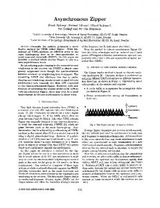
A. FPGA Architecture A basic FPGA tile consists of a cluster, two connection boxes (C-box) and a switch box (S-box). A system described in a high-level language is decomposed into implementable modules, which correspond to clusters, and whose interconnection information is mapped into C-boxes and S-boxes. C-boxes is for connecting a cluster to interconnect-paths and S-boxes is for switching interconnect-paths. Logic cells in a cluster share inputs and outputs, and each logic cell is a PCHB (Pre-charged Half Buffer) [6], which consists of a pulldown computation stack, validity trees of inputs and outputs, and so on. The cell contains programmable SRAM bits: some of the bits are for configuring computations and the others are for setting patterns of communication between cells. There are two types of soft errors in FPGA: an error in computation parts (e.g., pulldown stacks) can bring about wrong computations temporarily, and an error in programmable bits
C-box
Logic Cell
C-box
C-box
S-box
Cluster Basic Tile
C-box
Fig. 1.
S-box
FPGA Architecture
B. Duplicated Double-checking Logic Cell The key idea of detecting or correcting errors in any system is redundancy. Triple modular redundancy (TMR) with voters is widely used to correct an error in synchronous circuits. But in QDI circuits dual copies are enough to restore corrupt data due to the stability property of QDI circuits. The stability property is a system property that if the assignment of output of a gate starts, inputs of the gate hold current values until the assignment is completed. Let us define a duplicated double-checking (DD) circuit. To get a DD circuit, we duplicate all gates in the original circuit and double-check all output nodes. Double-checking duplicated output nodes za , zb means that we replace za , zb with new nodes (e.g., za0 , zb0 ) and introduce two C-elements that share the inputs za0 , zb0 and whose outputs are za and zb . Figure 2 shows what a DD gate looks like. DD circuits can
x y
x yaa
z’a
C
za
C
zb
z x ybb
Fig. 2.
z’b
AND gate and DD AND Gate
tolerate multiple soft errors unless two or more errors occur in two adjacent DD gates[7]. The soft-error-tolerance of DD circuits is based on the fact that at least one duplicated variable of each pair in DD
circuits will contain a correct value, and the double-checking scheme prevents corrupted values from propagating to subsequent gates. That is, an error is confined between doublechecking C-elements, and the correct data can be reconstructed due to the stability property. Although soft errors can delay computations of the system, the correctness of computations is still guaranteed. Actually the DD scheme is a sufficient construction to get soft-error tolerance, and for optimization, some of double-checking C-elements in DD circuits can be omitted without breaking soft-error tolerance. C. Dual Interlocked Programmable Bits Generally programmable SRAM bits in FPGA employ two conventional cross-coupled inverters, which consist of 6 transistors, as shown in Figure 3 (a). Although the DD scheme can be adapted to obtain soft-error tolerance of programmable bits, a small modification of Calin’s dual interlocked (DI) 12transistor memory cell [8] is more efficient and also suitable to the DD scheme. Four nodes (e.g., ca , ca , cb , cb ) in a DI programmable bit encode a bit as two pairs of complementary values (i.e., 0101, 1010), as shown in Figure 3 (b). The logic state of each node is controlled by two complementary adjacent nodes, and one of the adjacent nodes always keeps a correct value to restore corrupt data. For example, an error at ca in 0101 state causes cb to be an unknown state because both pullup and pulldown transistors are turned on, but ca still holds 1 that is used to restore ca . Other erroneous cases can be similarly analyzed. Each DI memory can tolerate any single error or two errors in pair of non-adjacent nodes (i.e., {ca ,cb }, {ca ,cb }). Programming
Programming
c
c
ca
(a)
Fig. 3.
ca
cb
cb
(b)
(a) Programmable Bit (b) Dual Interlocked Programmable Bit
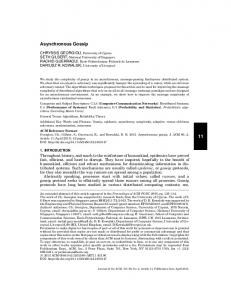
D. Soft-error tolerant FPGA Cell We can construct a FPGA logic cell based on the DD scheme with DI programmable bits. Figure 4 shows the construction of a soft-error tolerant logic cell. Two original cells are interweaved by double-checking C-elements. In the same manner, we can construct soft-tolerant S-boxes and C-boxes. The area of the whole FPGA will be enlarged approximately by a factor of two. III. C ONCLUSION When a soft error happens, a QDI FPGA may perform incorrectly or halt. The method of duplicating and doublechecking nodes provides a way of protecting QDI systems
o1b
goa cb cb ca
ca
o1a
C
o0a
C
...
o0b
... Computation Pulldown Networks ... goa input data a
output data a
Output Validity
...
ova
ovb
C iva Input C Validity ivb input_enable a
Completion Tree
output_enable a
ieb
C
iea
goa
C
ga gb o1a
gob ca ca cb
cb
...
o1b
C
o0b
C
o0a
... Computation Pulldown Networks ... input datab
gob
output data b
Output Validity
...
ovb
ova
C ivb Input C Validity iva input_enable b
Completion Tree
C gob
output_enable b
iea ieb
C
gb ga
: Half of DI Programmable Bit C : Double-Checking C-element
Fig. 4.
Soft-error Tolerant FPGA Logic Cell
from soft errors. The stability property of QDI systems permits us to avoid triplicating logic cells. The dual interlocked design is used for programmable bits, and it is more efficient than direct application of the DD scheme to programmable bits. Because the design of soft-error tolerant logic cells is straightforward, we can easily convert existing circuits into soft-error tolerant design and adapt existing synthesis procedures to the duplicated cells. R EFERENCES [1] Actel Corporation, “Trends in the ASIC Marketplace”, http://www.actel.com/documents/SERppt.pdf, June 2002. [2] Alain J. Martin, “Synthesis of Asynchronous VLSI Circuits”, Formal Methods for VLSI Design, ed. J. Staunstrup, North-Holland, 1990. [3] Wonjin Jang and Alain J. Martin. “SEU-tolerant QDI Circuits”. 11th Proc. on Async. Circuits and Systems Mar, 2005. [4] Catherin G. Wong, Alain J. Martin, and Peter Thomas. “An Architecture for Asynchronous FPGAs” Proc. IEEE International Conf. on FieldProgrammable Technology, Dec, 2003. [5] J. Teifel and R. Manohar. “Programmable Asynchronous Pipeline Arrays” Proc. 13th Intl. Conf. on Field-Programmable Logic and Application, Dec, 2003. [6] Andrew M. Lines, “Pipelined Asynchronous Circuits”, M.S. Thesis, Dept. of Computer Science, California Institute of Technology, 1995. [7] Wonjin Jang and Alain J. Martin. “Soft-error Robustness in QDI Circuits”. 1st Workshop on System Effects of Logic Soft Errors April, 2005. [8] T.Calin, M. Nicolaidis, R. Velazco “Upset Hardened Memory Design for Submicron CMOS Technology” IEEE Transactions on Nuclear Science Vol 43, No.6, Dec, 1996.