information and logic gates for processing this. information. ... available gates on the digital chip, the minimizing ..... [5] Alan Marshall, Polly Siegel, Bill Coates,.
Software for The Minimization of The Combinational Logic Functions
SOFTWARE FOR THE MINIMIZATION OF THE COMBINATIONAL LOGIC FUNCTIONS Rotar Dan “Vasile Alecsandri” University, Bacau, Romania
Abstract – An important component of the command and control circuit for the mechatronic systems is the logical combinational circuit. For their design, methods of minimization and optimization are often used. These methods also apply to the PLA, ASIC or FPGA circuit design, being widespread in the digital circuit design [1]. The Karnaugh map method and the Quine McCluskey algorithm are classical methods of minimization. Using the Karnaugh tabular method for minimization is time consuming, and if it is done manually, it is not easy to do for more than six variables. When the logic function has more variables, as it happens in most practical situations, the method developed by Quine and McCluskey is more accessible. This method can be easily implemented as a computer program [2]. The development of the software and hardware components of the computer systems allows the simplification of the minimization algorithm if the program has an acceptable execution speed. This paper presents the algorithm and the adequate program for the minimizing of the combinational logic functions up to 20 variables, but the number of variables is only limited by the computer system’s memory. The program is developed in Visual Basic. The algorithm is based on the consecutive clustering of the terms, starting with grouping the terms with a single change of a variable into two terms with a variable of the same rank. Following the grouping, the result will be new terms with one of the variables eliminated. The clustering algorithm ends when variables cannot be grouped any longer. This algorithm is similar to the Quine McCluskey algorithm, but it is more simplified because it eliminates a number of activities required by the Quine McCluskey algorithm. Keywords – software, mechatronics systems, combinational logic functions 1. Introduction There are two categories of digital circuits: combinational logic circuits that exclusively consist of logical gates and sequential logic circuits that consist of memories, which are components for storing information and logic gates for processing this information. Generally, memories have a standard structure and a well-defined behavior. Because of this, the design of digital circuits, regardless of their type, also implies the design of a combinational logic component from the circuit’s structure. The designing of combinational logic circuits is commonly called logic synthesis and currently, there are a number of methods devoted to this activity. The design work usually begins with an analysis of the function / functions that must be met by that circuit. At this stage the necessary output values of the logic circuit are determined according to the values of the variables’ input values. The result of this analysis takes the form of a truth table of the function. The synthesis of the combinational logic function often requires a minimizing operation that seeks to reduce the number of components needed to achieve that function. It must be mentioned here that
not all currently used methods of synthesis require minimization, but this operation is often very useful. For example, when using a PSoC (Programmable System on Chip) device with a limited number of available gates on the digital chip, the minimizing operation is very useful [3]. Among the traditional minimizing methods used for the combinational functions (also called binary logical function or Boolean functions), the Karnaugh method and the Quine-McCluskey method will be briefly presented [1]. E.W. Veitch first suggested the use of a special form of the Venn diagrams in order to simplify with their help the combinational logic functions. Shortly after, M. Karnaugh also suggests a modified form of the Venn diagrams with the same purpose. The diagrams called the Karnaugh maps resulted in this way. The Karnaugh maps are currently used to represent Boolean functions with a relatively small number of variables. These diagrams are useful for minimizing Boolean functions because they easily allow the detection of identities similar to the type Eq. 1.
x + xy = x
xy + x y = x
(1)
x + xy = x + y
The Romanian Review Precision Mechanics, Optics & Mechatronics, 2010 (20), No. 37
95
Software for The Minimization of The Combinational Logic Functions Generally, a Karnaugh map for a Boolean function of n variables is drawn as a square or a rectangle divided into 2n compartments. Each compartment is reserved for a canonical term of the function, i.e. for one of the 2n n-uples of the function or for the corners of the n-dimensional cube from the geometrical representation of the function. In this way, a Karnaugh diagram will be represented by a table with m rows and p columns which meet these conditions m x p = 2n and m + p = n. The heads of the table will contain the possible combinations for the function variables written in the Gray code. Putting variables on rows and columns can be done in several ways; the only condition being the correct filling in of the table. When minimizing the function the fact that a Karnaugh diagram is a closed surface and so the top and bottom edges of the table and also the left and right edges are adjacent (are attached) has to be taken into consideration. The Quine-McCluskey method is an algebraic method for minimizing Boolean functions with a large number of variables, for which the Karnaugh map method is difficult to use. This method, based on the same principles as the Karnaugh map method, is easier to apply for the functions with a large number of variables because the method involves the consecutive building of some tables to determine the minimum form of a function. The algorithm that is lies at the basis of the Quine - McCluskey method can be easily programmed thus allowing the automatic minimization of the large functions. The method is applied in two steps: 1. the first step determines the prime implicants of the function; 2. the second step determines the essential prime implicants to give coverage of the function with a minimum cost. A different approach is the ESPRESSO algorithm. This algorithm was developed by Brayton e.a. at the Berkeley University, California, [4]. This algorithm works with "cubes" which are the product of the function’s terms that are iteratively determined. This way of working separates this algorithm from the classical ones that are based on the factorization of the function in mini terms. The minimizing result does not lead to an absolute minimum but the obtained results are very close to it and the result does not include redundant terms. Compared with other methods, this method can be done more efficiently on a computer program. Using this algorithm on a computer system leads to a calculation time and a lower memory consumption. The algorithm does not impose restrictions on the number of variables, output functions or on the number of blocks of the combinational logic function that is minimized. Combinational logic functions with dozens of outputs and dozens of variables can be easily 96
calculated using this algorithm. For the ESPRESSO algorithm, it is necessary to submit the truth table of the function for minimization at the entry point and the minimized function will be obtained at the output. Basically, this algorithm tries to use the product of the terms at as many output functions for the given function. There is though the possibility that each output function to be treated independently. In this way the algorithm can be used effectively in programmable logical matrixes on two levels such as the PLA (Programmable Logic Array) or PAL (Programmable Array Logic). Given the performances of the EXPRESSO algorithm it is currently used in many applications involving the use of FPGAs (Field Programmable Gate Array) or ASIC (Application Specific Integrated Circuit). 2. Binary function minimization software The minimization program is implemented in Visual Basic programming environment version 5.0. With this program, minimizing the combinational logic functions with up to 20 variables can be done. The number of the binary function’s variables can be increased if the computer system resources allow this. A combinational logic function with 20 variables can have no more than 1,048,576 terms which in most practical cases is sufficient. The first step is grouping the terms in which a single variable has different values in distinct terms. The variable that changes must be kept at the same rank in the terms that are grouped. The second step is trying to group the already grouped terms. The grouped terms can be grouped again if the following conditions are accomplished: the variables already grouped are at the same rank in both terms and only one variable changes its value in the terms that are grouped. The algorithm ends when terms cannot be groups any longer. The coverage of the binary function is determined on the prime implicants’ table obtained. The coverage represents the essential and nonessential implicants’ selection that can fully describe the function. A sorting of the found coverage is made and they are displayed in the ascending order of the cost. A simple example of a function with four variables with four terms each will be considered below. This function can be written in the disjunctive normal form as: f4 = P5 + P7 + P13 + P15
(2)
which can be written in canonical form as: f ( x3 x2 x1 x0 ) = x3 x2 x1 x0 + x3 x2 x1 x0 + x1 x2 x1 x0 + x3 x2 x1 x0 (3)
The Romanian Review Precision Mechanics, Optics & Mechatronics, 2010 (20), No. 37
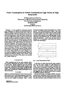
Software for The Minimization of The Combinational Logic Functions The initial terms of the function are put in a matrix called in the program "Terms1". In the first step, the terms that can be grouped are placed in the matrix "Terms2". The terms that could not be
grouped are placed in a matrix named "End". The terms of the matrix „End” represent the prime implicants of the binary function. For the function in the example, the situation in Figure 1 is presented.
Terms1
Terms2
0101
01X1
0111
11X1
End
1101 1111 Figure 1: Step 1. Initial grouping terms Next, the contents of the matrix „Terms2” are transferred in the matrix "Terms1" and the
process is repeated (Figure 2).
Terms1
Terms2
01X1
X1X1
End
11X1
Figure 2: Grouping terms already grouped After this phase, it appears that the terms cannot be grouped any longer and thus the matrix "Terms2" will be empty, this leading to the completion of the algorithm. The term from the matrix "Terms1", which was not grouped, is
Termeni1
transferred to the matrix "Final". The coverage of the function is determined (in our example it is not the case) and the sorting is made. The result of the minimization is found in the matrix "Final" (Figure 3).
Termeni2
X1X1
Final X1X1
Figure 3: End algorithm
The Romanian Review Precision Mechanics, Optics & Mechatronics, 2010 (20), No. 37
97
Software for The Minimization of The Combinational Logic Functions
First entering the number of the function variables, then the decimal indexes of terms are introduced. It displays the current number of the term introduced.
The Index of the introduced term in decimal format. Binary equivalent of the index term.
Button to change the number of variables or to initialize the program.
After two terms are introduced, the button that triggers the minimization action becomes active.
Exit program. The result of the minimization.
Figure 4: The main window of the minimization software When starting, the program displays a main window that allows the user to enter the terms of the binary function and to launch the minimizing operation (Figure 4). The user must enter at the beginning the number of variables of the Boolean function for minimization. The user receives some information about how the program works and about the maximum number of terms that can be introduced. The introduction of the terms by their index follows after that. The program provides assistance on the input process and on the errors that can occur, by displaying additional windows. The entered terms are also shown in their corresponding binary code for control. After entering all the terms (of the Boolean function) the minimization process starts. The resulted terms are displayed in the result window and on the position of the eliminated variables the symbol "X" is displayed. 3. Conclusions The program presented in this paper uses a simplified algorithm Quine-McCluskey. The code developed is optimized for the increase of the execution speed. 98
The main advantages of this program are the possibility of the rapid determination of the minimized forms and the increase of the designing efficiency of digital circuits configured by the user. The possibility of implementing tests for minimum convenient forms is also another advantage of the minimization program. Additional terms can be introduced or different configurations can be tried in order to achieve optimum results. The program's main drawback is the fact that increasing the number of variables of the binary function uses an appropriate amount of memory. The tests conducted when designing and the obtained results show that this program is a useful tool that increases productivity. 4. References [1] G. De Micheli, "Synthesis and Optimization of Digital Circuits", McGraw-Hill Science Engineering, 1994 [2] S. Ahmand, R. Mahapatra, “M-trie: an efficient approach to on-chip logic minimization”, Proceedings of the 2004 IEEE/ACM
The Romanian Review Precision Mechanics, Optics & Mechatronics, 2010 (20), No. 37
Software for The Minimization of The Combinational Logic Functions
[3]
[4]
[5]
[6]
International conference on Computer-aided design, p.428-435, November 07-11, 2004 Erik Brunvand, Steven Nowick, Kenneth Yun, “Practical advances in asynchronous design and in asynchronous/synchronous interfaces”, Proceedings of the 36th ACM/IEEE conference on Design automation, p.104-109, June 21-25, 1999, New Orleans, Louisiana, United States R.K. Brayton, A. Sangiovanni-Vincentelli, C. McMullen, G. Hachtel, "Logic Minimization Algorithms for VLSI Synthesis", Kluwer Academic Publishers, 1984 Alan Marshall, Polly Siegel, Bill Coates, “Designing an Asynchronous Communications Chip”, IEEE Design & Test, v.11 n.2, p.8-21, April 1994 J. W. J. M. Rotten, M. R. C. M. Berkelaar, C. A. J. van Eijk, M. A. J. Kolsteren, “An efficient divide and conquer algorithm for exact hazard free logic minimization”,
Proceedings of the conference on Design, automation and test in Europe, p.749-754, February 23-26, 1998, Le Palais des Congrés de Paris, France [7] Vigyan Singhal, Carl Pixley, Adnan Aziz, Shaz Qadeer, Robert Brayton, “Sequential optimization in the absence of global reset”, ACM Transactions on Design Automation of Electronic Systems (TODAES), v.8 n.2, p.222251, April 2003 [8] Wilsin Gosti, Tiziano Villa, Alex Saldanha, Alberto Sangiovanni-Vincentelli, “FSM Encoding for BDD Representations”, International Journal of Applied Mathematics and Computer Science, v.17 n.1, p.113-124, Number 1 / March 2007 [9] Nikhil Saluja, Kanupriya Gulati, Sunil P Khatri, “SAT-based ATPG using multilevel compatible don't-cares”, ACM Transactions on Design Automation of Electronic Systems (TODAES), v.13 n.2, p.1-18, April 2008
The Romanian Review Precision Mechanics, Optics & Mechatronics, 2010 (20), No. 37
99