The 2010 IEEE/RSJ International Conference on Intelligent Robots and Systems October 18-22, 2010, Taipei, Taiwan
Sound Source Separation by Using Matched Beamforming and Time-Frequency Masking Jounghoon Beh*, Taekjin Lee†, David Han‡, Hanseok Ko◊ * UMIACS, University of Maryland, College Park, USA † UBICOD Co. Ltd, KOREA ‡ Office of Naval Research, USA ◊ Korea University, KOREA
[email protected],
[email protected] i1
Abstract— This paper proposes a two-stage algorithm to separate two sound sources by using matched beamforming and time-frequency masking techniques. At first, beamforming was used to separate the sound mixtures back to the original sources while preserving the original contents to the maximum extent. The residual interference was then suppressed by the time-frequency masking technique. A sequential least squares method was used in developing a matched beamformer to estimate the relative transfer function (RTF). From experimental results, it has been shown that the proposed method exhibits improved performance in sound source separation compared to conventional methods. Signal enhanced factor (SEF) was improved by an average of 8.39 dB over the baseline.
I. INTRODUCTION The key objective of a speech based human-robot interface is to accurately recognize operator’s acoustic commands. In real life environments, the operator’s voice command is often corrupted by noise such as competing voices as in the case of cocktail party problem or nonverbal background noise that would drastically degrade performance of any speech recognition system. To alleviate this, several approaches were suggested on the subject of separating the mixed sounds into the respective sources. Independent component analysis (ICA) and beamforming are some of the representative methods. ICA based method utilizes independent characteristics of each sound source by assuming that each input source is statistically independent. In contrast to ICA, beamforming based method needs to know the direction of the desired source to reduce other speech and noise. The method separates the audible sources by separating them in terms of their directions. Time-frequency masking (TFM) method [1] separates sound sources by masking unwanted sounds in the time-frequency domain. The method primarily relies on clustering of the mixed signals with respect to their amplitudes and time delays. The motivation of this paper is to develop a sound source separation system for the purpose of enhancing the quality of the robot operator’s speech. For the separation of the sound sources, a matched beamformer is employed first with an assumption that the locations of the operator and other competing speakers are known as assumed in [2]. The matched beamformer employs a least square method to
978-1-4244-6676-4/10/$25.00 ©2010 IEEE
estimate the impulse response, also known as a transfer function (TF), between the sound sources and the input signals of the microphone array. Existing least square based methods require a set of input data blocks for initial calibration [3]. However, this approach may result poor performance due to problems such as memory insufficiency or low performance of the TF estimation in the case of moving sound sources. This would affect the sound source separation process which would eventually degrade the overall performance. An adaptive form of a least squares solution using the least mean squares (LMS) was introduced in previous studies [4]. However, this led to a significant increase in computational load. To counter these problems and to further improve the performance, this paper suggests the use of a sequential least square method. The remainder of this paper is organized as follows. Section II describes the proposed algorithm in detail. Experimental results are discussed in Section III. Concluding remarks are presented in Section IV. II. PROPOSED ALGORITHM Let s(m) and c(m) denote respectively the voice signal of operator and competing speaker where m is the discrete time index. Then the observed signal at ith microphone of array, yi(m), is assumed to be given by yi (m) hi (m) * s(m) g i (m) * c(m) ni (m), i 1,..., M (1) where hi(m) and gi(m) represent impulse responses between the ith microphone and each of the two sources. M denotes the number of microphones consisting of the array, and ni(m) is ambient noise signal which is assumed to be stationary and uncorrelated with the source signal. The signal model of interest in this paper is formed in the Short Time Fourier Transform (STFT) domain. yi(m) is segmented into overlapping frames with analysis window of size W and the shift size of Z. We form the signal in the lth frame as yi (l , v) yi (lZ v) w(v), 0 v W 1 , (2) where w(v) represents an analysis window. By using Fourier transform, (2) becomes Yi ( l , )
W 1
y (l v ) e i
j v
(3)
v0
In STFT domain, (1) can be rewritten as Yi (l , ) H i ( ) S (l , ) Gi ( )C (l , ) N i (l , ) .(4)
458
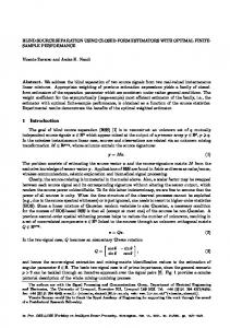
Fig. 1. Block diagram of the proposed algorithm. Our goal in this paper is to recover original signals S(l,) and C(l,) from the given observation Yi(l,) by using the matched beamformer and TFM. We illustrate the proposed algorithm in terms of a block diagram as shown in Fig. 1. First, the microphone array determines if there was any utterance from any of the parties by measuring the acoustic energy level collected and proceeds to estimating the associated TF once the collected level exceeds a threshold. We then proceed to estimate relative TFs (RFTs) that represent the relationships between the reference microphone and other microphones of the array. This is necessary as a part of a calibration process prior to the matched beamforming. Using the estimated RTFs from the prior step, matched beamformers are developed, with beam width being constrained to the degree such that preservation of the original source contents was maximized. The resultant outputs from the matched beamfomer are roughly separated back to the two person’s voice, however each of the separated signals may yet contain the acoustic contents from the other party’s voice. To further reduce the residual voice contaminated from the other speaker, we employ the TFM based on the spectral power ratios between the two separated signals obtained from the matched beamforming.
A. Detecting sound from a direction of interest For estimating RFT corresponding to a direction of interest, it is necessary to obtain certain amount of acoustic data from the direction. In order to do so, it needs to be determined whether an acoustic event occurred or not. Occurrence of an acoustic event is determined by examining its acoustic energy intensity from its direction. Direction of the speaker is determined from a visual sensor as it was assumed in [2]. As the operator gives verbal commands to the robot, the audible signal reaches the array with an incidence angle . In our implementation we used 4-channel microphone array, denoted by m1 ~ m4 as shown in Fig. 2, and we employed the far-field assumption that the propagated wave reaches the array in planar manner. With respect to the incidence angle, signal arrives at each microphone with corresponding time-delays.
Fig. 3. Energy intensity as a function of time and angle of the sound source location. Fig. 2. The incidence of acoustic wave to microphone array in planar manner.
Steered response power phase transform (SRP-PHAT) [5] is used for examining the acoustic energy intensity. SRP-PHAT value, SP(l,), as a function of frame l and
459
direction is obtained by SP (l , )
M
M
2
(l , )Y (l , )Y ij
i 1
j 1
i
* j
(l , ) e
j ij ( )
d .(5)
0
where ij ( ) denotes the time-delay of the signal between the ith and jth microphones with respect to . The phase transform (PHAT) weighting function ij (l , ) is defined as
ij (l , )
1 . | Yi (l , Y j* (l , ) |
(6)
Fig. 3 illustrates the energy intensity by using (5) when two speakers alternatively utter, and they are located at angles of -40˚ and 30˚ respectively. After examining the energy intensity, we determine whether an acoustic event occurred in the direction of interest, e.g. operator’s angle. B. RTF estimation RTFs of Hi() and Gi() in (4) are defined as ratios of TFs between the ith microphone and the reference one. Note that we choose the leftmost one, which is the 1st microphone, as a reference. Pi ( )
H i ( ) , i 1,..., M , H 1 ( )
(7a)
Gi ( ) , i 1,..., M . (7b) G1 ( ) We propose a RTF estimation method which employs the sequential-mode least squares (SLS) [6]. There are two advantages of the proposed method over the conventional methods [3] employing the batch-mode least squares (BLS). First, it provides flexibility in collecting the acoustic data to estimate the RFTs. For the methods utilizing the BLS, it is required that acoustic data only from corresponding direction should be collected for a set period of time. In our experiments of implementing the BLS based method, at least 3.2 seconds of collection period was needed for sufficient RTF estimations to guarantee reasonable performance of the matched beamformer. Our proposed method accomplishes the estimation by updating the RFT on frame-by-frame basis, therefore there is no threshold acoustic collection period needed. The other advantage is memory efficiency achievable in hardware based processing. In the BLS implementation, in terms of bytes, the memory required is {(# of microphones – 1) × (2 × # of frequency bins) × (# of frame to be used in estimation) × (# of bytes w.r.t. variable type)} per a source. As we mentioned in this section, RTF is estimated per frame. It does not need to arrange memory of a hardware for the estimation. An RTF is estimated when the current input frame is determined to contain an acoustic event caused by a person (operator or competing speaker). Estimation of an RTF associated with an operator location is considered as an example. Observation Yi(l,) in (4) is rearranged by using (7a) as Yi (l , ) H i ( ) S (l , ) N i (l , ) (8) Pi ( )Y1 (l , ) U i (l , ), Qi ( )
where Ui(l,) is formed as U i (l , ) N i (l , ) Pi ( ) N1 (l , ). (9) In (8) and (9), we assume that the analysis interval of the STFT is sufficiently long enough for the observed signal in lth frame, yi(l,r), to be considered stationary. In addition, we have assumed that the ambient noise ni(m) is stationary. Thus, the cross power spectral density (CPSD) between Yi and Y1 can be written as YiY 1 (l , ) Pi ( ) Y 1Y 1 (l , ) UiY 1 ( ). (10) Note that since Ui is uncorrelated with Si, UiY 1 is independent of l. We estimate YiY 1 (l , ) by the recursive averaging ˆ (l , ) denote estimates of along the frame. Let YiY 1
YiY 1 (l , ) . Then, (10) is rewritten as ˆ (l , ) P ( ) ˆ ˆ (l , ) (l , ) YiY 1 i Y 1Y 1 UiY 1 (11) ˆ Pi ( ) YiY 1 (l , ) UiY 1 ( ) i (l , ), ˆ (l , ) is the estimation where (l , ) (l , ) i
UiY 1
UiY 1
error. We can now consider the acoustic data in a certain duration corresponding to K frames for estimating Pi(). Via the BLS approach, Pi() can be obtained from the following equations [3][7]: ˆ (1) ( ) ˆ (1) ( ) 1 i(1) ( ) YiY 1 Y 1Y 1 (2) (2) (2) ˆ ( ) ˆ i ( ) ( ) 1 YiY 1 Y 1Y 1 Pi ( ) (12) ( ) 1 UiY ( 1 ) K ˆ ( K 1) ( ) 1 ˆ ( K 1) ( ) ( ) i Y 1Y 1 YiY 1 (K ) ( K ) K ( ) ˆ ˆ i ( ) YiY 1 ( ) Y 1Y 1 ( ) 1 where superscript (·) denote the frame number of data used for the BLS. The idea behind the SLS is to recursively update the least squares estimate as new observations are acquired [6]. The following vectors are defined for sequentially solving the equation (12). ˆ (1) ( ) ˆ ( 2 ) ( ) ... ˆ ( k ) ( )]T , y i( k ) [ (13) YiY 1 YiY 1 YiY 1 ( k ) ˆ a [ ( ) 1] , (14) k
Y 1Y 1
ˆ (1) ( ) Y 1Y 1 (2) ˆ ( ) A k Y 1Y 1 ( ) k ˆ Y 1Y 1 ( )
n i( k )
1 1 A k 1 , a k 1 [ i(1) ( ) i( 2 ) ( ) ... i( k ) ( )]T .
θ i [ Ri ( ) UiY 1 ( )] Then, (12) can be rewritten as y i( k 1) , y i( k ) ( k ) ˆ ( ) YiY 1 where y i( k 1) A k 1θ i n i( k 1) , ˆ ( k ) ( ) a θ ( k ) ( ) .
460
T
YiY 1
k
i
i
(15)
(16) (17)
(18a)
(18b) (18c)
Let θˆ i( k ) denote the SLS solution given the measurement ˆ ( k ) ( ) . By using (14) and (18), and the given YiY 1 measurement vector y (k ) , θˆ ( k ) is determined as follow: i
i
θˆ i( k ) ( A kH A k ) 1 A kH y i( k )
(19) ˆ ( k ) ( )). ( A kH1 A k 1 a kH a k ) 1 ( A kH1 y i( k 1) a kH YiY 1 Let Dk denote the inverse of the Gram matrix of Ak such that D k ( A kH A k ) 1 . (20) Use of the matrix-inversion lemma and (20) leads us to ( A kH1 A k 1 a kH a k ) 1 (D k 11 a kH a k ) 1 . (21a) D k 1 k D k 1a kH a k D k 1 where k1 1 a k D k 1a kH . (21b) Then, substituting (20) and (21) into (19) yields the SLS solution which is recursively updated. ˆ ( k ) ( )} θˆ ( k ) (D D a H a D ){A H y ( k 1) a H k 1
i
k
k 1
k
k
k 1
k 1
i
k
YiY 1
D k 1 A kH1 y k 1 k D k 1a kH a k D k 1 A kH1 y i( k 1) ˆ ( k ) ( ) D a H (1 ) ˆ ( k ) ( ) D k 1a k YiY 1 k 1 k k YiY 1 ( k 1) H (k ) ( k 1) ˆ ˆ ˆ θ D a { ( ) a θ } i
k
k 1
k
YiY 1
k
(22)
i
Pi(), the first element of θˆ i( k ) which estimates the RTF between the ith microphone and the speaker is the key signal to be captured here. The other RTF, Qi(), can be obtained via the similar procedure. Since we have assumed the background noise is stationary, by using (11) and (18c) the ˆ ( k ) ( ) and difference between the estimated CPSD YiY 1 ( k 1) ˆ aθ would lead to the estimation error of RFT as follow:
where ( ) is defined by ˆ H ( )Pˆ ( ) Q ( ) (26) ˆ H ( ) || || Pˆ ( ) || || Q with the cosine of the angle between the Q() and P() forming in an inner product space. FS() is the desired filter response of the matched beamformer with respect to the source S (l , ) in (4). Likewise, the matched beamformer gain toward competing speaker is given by ˆ () Q Pˆ () * (e j ) 2 ˆ () || ˆ () || || Pˆ () || || Q || Q WC () FC () . (27) 1 || () ||2 where FC() is the desired filter response of the matched beamformer with respect to the source C (l , ) . Let Y(l , ) denote the input signal vector of array, i.e. ~ ~ [Y1(l, ) Y2 (l, ) YM (l, )]T , and let S (l,) and C(l,) denote the beamformer outputs with respect to the operator and a competing speaker, respectively. By using (25) and (27), the beamformer outputs are written as S~(l, ) WSH () (28) ~ H Y(l, ) . C(l, ) WC ()
D. Time-frequency masking Due to imperfect estimations of the RFTs, the beamformer outputs may yet contain acoustic contents from the other party’s voice. We employ the spectral power based TFM to further reduce the noise. The TFM is based on the windowing-disjoint orthogonal (WDO) [1] assumption which means that two signals in time-frequency domain such as the k i STFT domain are assumed not to coexist at the same time and ( k ) ( k 1 ) ( k ) ( k 1 ) ( k ) ˆ ( ) ˆ ( ) a θˆ ˆ ˆ ˆ Pi ( ) YiY 1 k i Y 1Y 1 UiY 1 ( ) Pi Y 1Y 1 (l , ) same frequency bin. In application to our problem, it can be ˆ ( k 1) ( ) stated concisely as UiY 1 (k ) ( k 1) S(l, )C(l, ) 0, l, . (29) ˆ ˆ Y 1Y 1 ( Pi ( ) Pi ( )) (23) Equation (22) and (23) tells us that the error is reflected to the Since the beamformer gain function is a linear operator, the WDO assumption can be applied to the beamformer output as update of the current estimate of RTF with the gain k D k 1a kH . ~ ~ S (l, )C(l, ) 0, l, . (30) C. Matched beamformer We propose a mask function based on the spectral power The matched beamformer was originally proposed as a part of ratio which is defined by dual transfer function generalized sidelobe canceller [7]. In || S~(l,) ||2 . RS (l,) 10log10 ~ (31) the proposed algorithm, its role is to form the beam toward a 2 || C(l,) || person while nulling the audio signal coming from the other person’s location. We briefly describe the procedure in this Note that (31) is spectral power ratio of the operator. In our section. experiment, we observed that instantaneous power of the Let P() and Q() denote the RTF vectors formed by beamformer outputs at the same frame l and frequency , i.e., ~ ~ using (7) such that S (l,) and C(l,) , have shown a discernable difference with T P ( ) [1 P2 ( ) ... PM ( )] , (24a) respect to the dominant voice. In Fig. 4, we illustrate it in T Q( ) [1 Q2 ( ) ... QM ( )] . (24b) terms of a histogram from the operator’s side. This histogram With estimates of the RTFs, the matched beamformer gain for was built by using 300 seconds of speech data exclusive from forming beam toward the operator is given by the testing data used for performance evaluation. ˆ () Pˆ () Q () ˆ () || || Pˆ () ||2 || Pˆ () || || Q WS () FS () (25) 1 || () ||2 461
Person 2
Normalized histogram 0.7
Person 1
Operator
0.6
-20˚ 10˚
Competing speaker
0.5
30˚ -40˚
0.4
0.3 m
20˚
20˚
0.3
0.2
Microphone array 5 cm
0.1
0
Fig. 5. Configuration of data recoding 0
10
20
30
40
50
Performance is evaluated objectively in terms of the signal enhancement factor (SEF) which is defined by
60
Spectral power (dB) Fig. 4. Spectral power histogram
The mask for extracting operator voice from mixed source is simply presented by 1, if RS (l,) T S (l, w) . (32) 0.01, otherwise. where T is threshold value. We decided the threshold as 2 dB based on the histogram in Fig. 4. Equation (32) means that if RS (l, ) is lower than T, then the corresponding time-frequency bin (l,) contains the competing speaker’s voice signal. Thus the signal at (l,) should be attenuated by 0.01. The mask for competing speaker’s voice is made via similar procedure through (31) and (32), and C (l, w) denotes the mask. Finally, the separated sources by using the proposed algorithm can be stated as ~ Sˆ(l, ) S (l, ) 0 S (l, ) ~ C (l, )C Cˆ (l, ) 0 (l, ) . (33)
0 WSH () (l, ) S Y(l, ) C (l, )WCH () 0 III. EXPERIMENTS
A. Settings For the evaluation of the proposed method, a microphone array was set up indoor as shown in Figure 5 for data recording. The size of the room was 5m 3.8m 2.5m (length, width and height), and the microphone array was located in the middle of the room . The 4-channel microphone array receives the input signals that consist of the stationary background noise and speech of ‘person 1’ and ‘person 2’. The source of ‘person 1’ moves from -40˚ to -20˚ with respect to the center normal of the microphone array. Similarly, the source of ‘person 2’ moves from 30˚ to 10˚. The voice sources are located 0.3m from the horizontal center of the microphone array. Stationary office sound is used for the background noise source.
SEF 10 log 10
averaged power of person1' s voice , (32) averaged power of (person2' s voice noise)
The SEF measures the amount of reduction of the other person’s speech signal in the processed signal. When the sound source separation is implemented successfully, the average power of the noise section decreases and the SEF increases. B. Results 1) RTF Estimation method evaluation: Fig. 6 shows the waveforms of the input and the matched beamformer output signals with respect to the RTF estimation method. We compared three methods, namely the BLS [3], the LMS [4], and the proposed SLS method. In this experiment, both the BLS and SLS methods initialize the estimated RTF when the source moves. Comparing (c), (d), and (e) of Fig. 6, it is clear that the proposed method is more effective than the conventional methods of separating the sound sources. The BLS requires a temporal span of input signal for its initialization process in estimating the RTF, while it cannot update the changes in RTF as speaker moves. The proposed SLS method has shown that only two frames are necessary to track the change associated with speaker movements. The SLS implementation performed better in residual noise reduction compared to the other conventional methods. The LMS method performed better than the BLS in noise reduction, and exhibited similar performance in terms of waveform preservation. However, in Table 1 the SLS method achieves the best performance in terms of the SEF. Table 1. SEF comparison Method SEF (dB) BLS (baseline) 10.59 LMS 17.63 SLS (proposed) 18.98
2) TFM simulation: Fig. 7 shows the waveforms of the input, the matched beamformer output, and ‘matched beamformer’ + TFM. We use real recording data for evaluation of the source separation by using TFM. In Fig. 7
462
Fig. 6. Waveform comparisons
comparing (b) and (c), we can see the TFM reduces further the residual noise caused by ‘person2’. Another real data that the proposed algorithm is applied can be downloaded from http://www.umiacs.umd.edu/~jhbeh. Person1
Person2
Mixed source
(a) Input signal (1st microphone)
the angular locations of speakers are known. In addition, we proposed the SLS method to estimate RTF for the matched beamforming. The SLS method recursively updates RTF estimate with current input signal, thus it requires minimal initialization period in data collection and results in significant reduction in memory requirement. In addition to these advantages over the conventional estimation methods, it is shown that the proposed SLS improves performance of the matched beamforming in terms of SEF. Waveform has shown that spectral ratio based TFM can further reduce the residual voice of other party in the beamformer output voice of desired speaker. ACKNOWLEDGEMENT Authors acknowledge that this research was funded by the Seoul R&BD (WR080951) Program. REFERENCES [1]
(b) After ‘matched beamforming’
[2] [3] [4] (c) After ‘matched beamforming’ + TFM
[5]
Fig. 7. Waveform of real data for evaluation and results
IV. CONCLUSIONS
[6]
We have presented the beamforming based sound source separation algorithm which operates under an assumption that
[7]
463
O. Yilmaz, S. Rickard, “Blind separation of speech mixture via time-frequency masking,” IEEE Trans. Signal Processing., vol.52, no. 7, July, 2004. J. Beh, T. Lee, S. Ahn, H. Kim, D. Han, and H. Ko, “Enabling Directional Human-Robot Speech Interface via Adaptive Beamforming and Spatial Noise Reduction”, Proc. of IROS 2007, pp. 3454-3459, Oct. 28 – Nov. 2, 2007. S. Gannot, D. Burshtein, and E. Weinstein, “Signal Enhancement Using Beamforming and Nonstationarity with applications to Speech,” IEEE Trans. Signal Processing, vol. 49, no. 8, Aug, 2001. I. Cohen, “Relative Transfer Function Identification Using Speech Signals,” IEEE Trans. Speech and Audio Processing, vol.12, no. 5, September, 2004
J. H. DiBiase, H. F. Silverman, and M. S. Brandstein, “Robust localization in reverberant room,” in Microphone Arrays, M. Brandstein and D.Ward, Eds, Springer, 2001. L. L. Sharf, Statistical Signal Processing: Detection, Estimation, and Time Series Analysis, pp.384-386, Addison-Wesley, 1991. G. Reuven, S. Gannot and I. Cohen, “Dual Source Transfer-Function Generalized Sidelobe Canceller”, IEEE Trans. Audio, Speech and Language Processing, vol.16, Issue 4, pp. 717-727,May, 2008.