Haydn-C and its parallel programming model; (b) a frame- work of optional ... [2] and SPARK [3]. They take a behavioral description in ANSI-C as input and.
University of California at Berkeley. Computer Science ... {maratb,graham}@cs.berkeley.edu ... D.2.6 [Software Engineering]: Programming Environments â.
are user-defined and not part of the programming language itself there is ... With ROSE, library developers define customized optimizations and build.
transformations into development environments will assist developers with this ... implemented in the programmer's development environment, then ... source-to-source transformation engine such as REFINE [1] or. TXL [2]. ... In order to enable.
Jun 1, 2005 - Data-flow transformations used in optimizing compilers are also use- ...... a specification of partial redundancy elimination, illustrating how two ...
and editing phases of software development. Transformations can be construed broadly. In addition to replacing existing code, transformations can also ...
Jun 14, 2010 - to the success of NeXT, the company Steve Jobs founded after leaving Apple in 1985. ...... latter inappropriately interrupted the 2009 MTV Video Music Awards (Gold, 2009). ...... Obama, Kanye West and trouble with Twitter.
For each transformation, together with the evaluation of the energy ... source code transformations can exploit full knowledge of the algorithm character- ... Due to the lack of space, despite the analysis we carried out considered a broader ... but
Aug 2, 2002 - adapted source code transformations can improve Grid application ... and storage resources, network based computing will soon offer to users ...
Software maintenance can be a difficult job, especially in the case of so-called ... We then show how to use the traversal functions in the new ASF+SDF Meta- ..... To make traversing lists of statements and lists of .... some of the ASF+SDF code in t
Verification of Source Code Transformations by ..... operator node as source is labeled by the operand position of its destination; an ...... Addison-Wesley.
2. Piecewise-affine expressions: Subscripts in the arrays and expressions in the .... Må® 2 a b. Fig. 2. The ADDGs of p
term balikbavan by joining the Tagalog words balik, to return, with bavan,
meaning town and ... They bring us stories about how much life in. America has
proved ...
projective transformation of a camera. ⢠Reduce to a single 4 by 4 homogeneous coordinates transformation matrix. ⢠Permit high speed ... Translation. ⢠Rotation.
directions is followed: source code obfuscation is achieved through source code .... 2http://www.semanticdesigns.com/Products/Obfuscators/CObfuscator.html.
Feb 24, 2015 - support source-level debug during RTL simulation, some do not. No current .... out modifying the original behavior of the program. This is.
Oct 1, 2016 - Published in October 2016 by JustJobs Network Inc. Acknowledgments: ..... social media and messaging applications like. WhatsApp. Workers ...
AML710 CAD. LECTURE 6. Transformations in ... coordinate system onto itself. ➢
The geometric model undergoes change relative to its MCS (Model Coordinate.
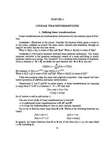
Linear transformations are (mathematical abstractions of) very common types of
func- tion. ... In some senses, matrices are the only examples of linear maps.
Wisconsin Press. R e a d a h Ameri. *Fuenzalida, F. et a1 (1970). El Indio y el poder en el Peru. Lima: Moncloa. Galeano, Eduardo (1973). The Open Veins of ...
Aug 18, 2003 - Tata Consultancy Services ..... This is a revised submission to the QVT RFP. Although .... complete superstructure to infrastructure translation. ix ...
to a line. The line about which the object is reflected is called the axis of
symmetry. ... To find the equation of the image of a line under a translation,
reflection, ...
been the powerful social attribution in my life, it is only one of a number of governing ... storied and that narrative is an ontological condition of social life.
work, and they managed it.' Any low points? 'We upset the neighbours with all the delivery lorries that came and went, a
Dorf and J.A Svoboda. ... Solution: The voltmeter measures the voltage across
the current source. ... Figure 3 Separating the circuit from Figure 2 into two parts.
Source Transformations Introduction The circuits in this set of problems consist of independent sources, resistors and a meter. In particular, these circuits do not contain dependent sources. Each of these circuits has a seriesparallel structure that makes it possible to simplify the circuit by repeatedly • • • •
Performing source transformations. Replacing series or parallel resistors by an equivalent resistor. Replacing series voltage sources by an equivalent voltage source. Replacing parallel current sources by an equivalent source source.
Each simplification is done in such a way that the voltage or current measured by the meter is not disturbed. Generally, that requires beginning the simplification at the opposite end of the circuit from the meter and then working toward the meter. Eventually, the circuit is small enough to be easily solved using Ohm’s and Kirchhoff’s Laws. Source transformations are discussed in Section 5.3 of Introduction to Electric Circuits by R.C. Dorf and J.A Svoboda. Series resistors are discussed in Section 3.4. Parallel resistors are discussed in Section 3.5. Series voltage sources and parallel current sources are described in Section 3.6.
Worked Examples Example 1: Consider the circuit shown in Figure 1. Find the value of the voltage measured by the voltmeter.
Figure 1 The circuit considered in Example 1.
1
Solution: The voltmeter measures the voltage across the current source. (The color-coded probes of the voltmeter indicate the reference direction of the voltage measured by the voltmeter.) Figure 2 shows the circuit after the replacing the voltmeter by the equivalent open circuit and adding a label to show the voltage measured by the meter. Figures 3 through 17 illustrate the use of source transformations and equivalent resistances to simplify the circuit.
Figure 2 The circuit from Figure 1 after the replacing the voltmeter by an open circuit.
Figure 3 Separating the circuit from Figure 2 into two parts.
Figure 4 The circuit from Figure 3 after doing a source transformation.
2
Figure 5 The circuit from Figure 4 after changing the order of parallel elements.
Figure 6 Separating the circuit from Figure 5 into two parts.
Figure 7 The circuit from Figure 6 after replacing parallel resistors with an equivalent resistor.
Figure 8 Separating the circuit from Figure 7 into two parts.
3
Figure 9 The circuit from Figure 8 after doing a source transformation.
Figure 10 The circuit from Figure 9 after changing the order of series elements.
Figure 11 Separating the circuit from Figure 10 into two parts.
Figure 12 The circuit from Figure 11 after replacing series voltage sources with an equivalent voltage source
4
Figure 13 Separating the circuit from Figure 12 into two parts.
Figure 14 The circuit from Figure 13 after doing a source transformation.
Figure 15 The circuit from Figure 14 after changing the order of parallel elements.
Figure 16 Separating the circuit from Figure 15 into two parts.
5
Figure 17 The circuit from Figure 16 after replacing parallel resistors with an equivalent resistor.
Figure 18 The reduced circuit. Figure 18 shows the simplified circuit after labeling the current i, of the resistor. Applying KCL at the top node of the circuit gives
8 2 i+ =2 ⇒ i=− A 3 3 The voltage measured by the meter, vm, is also the voltage across the resistor. Ohm’s law gives 2 v m = 3 − = −2 V 3
6
Example 2: Consider the circuit shown in Figure 19. Find the value of the resistance, R.
Figure 19 The circuit considered in Example 2. Solution: The voltmeter measures the voltage across one of the current sources. Figure 20 shows the circuit after the replacing the voltmeter by the equivalent open circuit and adding a label to show the voltage measured by the meter.
Figures 21 through 24 illustrate the use of source transformations and equivalent resistances to simplify the circuit.
Figure 20 The circuit from Figure 19 after the replacing the voltmeter by an open circuit.
Figure 21 Separating the circuit from Figure 20 into two parts.
7
Figure 22 The circuit from Figure 21 after doing a source transformation.
Figure 23 Separating the circuit from Figure 22 into two parts.
Figure 24 The circuit from Figure 23 after replacing series resistors with an equivalent resistor
Figure 25 The circuit from Figure 24 after numbering the nodes.
8
Figure 25 shows the simplified circuit after numbering the nodes. Let v1, and v2 denote the node voltages at nodes 1 and 2 respectively. Then the node voltages are v1 = -45 V
and
v2 = 5 V
Applying KCL at node 2 gives 5 −40 − 5 = + 4 =1 ⇒ R = 5 Ω R 15
9
Example 3: Consider the circuit shown in Figure 26. Find the value of the voltage measured by the voltmeter.
Figure 26 The circuit considered in Example 3. Solution: The voltmeter measures the voltage across the current source. (The color-coded probes of the voltmeter indicate the reference direction of the voltage measured by the voltmeter.) Figure 27 shows the circuit after the replacing the voltmeter by the equivalent open circuit and adding a label to show the voltage measured by the meter.
Figures 28 through 35 illustrate the use of source transformations and equivalent resistances to simplify the circuit.
Figure 27 The circuit from Figure 26 after the replacing the voltmeter by an open circuit.
10
Figure 28 Separating the circuit from Figure 27 into two parts.
Figure 29 The circuit from Figure 28 after doing a source transformation.
Figure 30 Separating the circuit from Figure 29 into two parts.
11
Figure 31 The circuit from Figure 32 after replacing parallel resistors with an equivalent resistor.
Figure 32 Separating the circuit from Figure 31 into two parts.
Figure 33 The circuit from Figure 32 after doing a source transformation.
12
Figure 34 Separating the circuit from Figure 33 into two parts.
Figure 35 The circuit from Figure 34 after replacing series resistors with an equivalent resistor.
Figure 36 The reduced circuit.
Figure 36 shows the simplified circuit after labeling the current and voltage of the 9 Ω resistor. Applying KVL to the loop circuit gives
9 − v m − 12 = 0 ⇒ v m = −3 V
13
Example 4: Consider the circuit shown in Figure 37. Find the value of the voltage measured by the voltmeter.
Figure 37 The circuit considered in Example 4. Solution: The voltmeter measures the voltage across 4 Ω resistor. (The color-coded probes of the voltmeter indicate the reference direction of the voltage measured by the voltmeter.) Figure 38 shows the circuit after the replacing the voltmeter by the equivalent open circuit and adding a label to show the voltage measured by the meter.
Figures 40 through 47 illustrate the use of source transformations and equivalent resistances to simplify the circuit.
Figure 39 The circuit from Figure 38 after the replacing the voltmeter by an open circuit.
Figure 40 Separating the circuit from Figure 39 into two parts.
14
Figure 41 The circuit from Figure 40 after doing a source transformation.
Figure 42 The circuit from Figure 41 after changing the order of series elements.
Figure 43 Separating the circuit from Figure 42 into two parts.
Figure 44 The circuit from Figure 43 after replacing series voltage sources with an equivalent voltage source.
15
Figure 45 Separating the circuit from Figure 44 into two parts.
Figure 46 The circuit from Figure 45 after replacing series resistors with an equivalent resistor.
Figure 47 The reduced circuit.
Figure 47 shows the simplified circuit. Voltage division gives 4 vm = 90 = 9 V 36 + 4