FACSIMILE OF THE PAPER LAURINI R. (1998) Spatial Multidabase Topological Continuity and Indexing: a Step towards Seamless GIS Data Interoperability. International Journal of Geographical Information Sciences. Vol. 12, 4, June 1998, pp. 373-402. ==================================
Spatial Multidatabase Topological Continuity and Indexing: a Step towards Seamless GIS Data Interoperability Robert LAURINI Laboratoire d’Ingénierie des Systèmes d’Information Université Claude Bernard Lyon I Institut National des Sciences Appliquées - Bât 404 F-69621 Villeurbanne - E-mail:
[email protected]
Abstract The scope of this paper is to present some problems and solutions concerning the federation of several geographic databases, in the context of interoperability. When a multidatabase query is executed, it is important to route it only to sites which are likely to contribute to the answer, whatever the fragmentation could be, geographic, thematic or heterogeneous. Secondly, when the answer implies several spatial databases, it is important that not only boundary alignment is achieved, but also topological continuity. After having described several general problems and concepts about distributed spatial databases and their integration, structures for spatial indexing in multidatabase systems will be described, giving emphasis to local and global spatial indices. A r-tree-like-based structure is proposed for organising those global indices. But, geographic fragmentation presents the great disadvantages to artificially cut geographic objects, such as roads, rivers, etc. In other words, some objects, called fragmented objects, have the particularity to have several database identifiers (one per site) and a mechanism must be provided in order to re-construct those objects when necessary. In this paper, special tools must be presented in order to ensure continuity of fragmented objects, semantically (at the level of identifiers), topologically (at level of data structure) and geometrically (at level of coordinates, possibly with errors). In order to accelerate queries against fragmented objects, some adjacency tables must be constructed. Only once spatial continuity is ensured, truly seamless GIS data will exist on Internet.
1
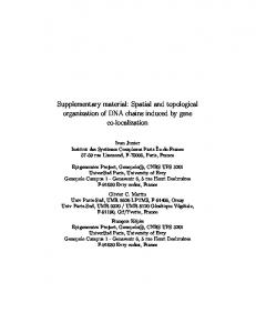
Rather than centralising geographic information into a unique database, an interesting solution is to federate all information stored into different databases or sites. Another aspect is that it can be very interesting also from any computer system to use geographic data stored in other computers. Let us think about applications such as natural hazard prevention and management in which several sites must be used in order to be informed about the circumstances and to manage the consequences. Another very common application copes with street repairs in which computers of different companies, namely companies dealing with water supply, gas, electricity, telephone and the municipality, must co-operate. Bearing in mind such kinds of applications, federating different geographic information systems is a way to solve these problems In different domains, GIS interoperability is a new key-concept. In this paper, interoperability will not be addressed in terms of data and treatments, but only data interoperability will be examined. In other words GIS interoperability being a dream for users and a nightmare for systems developpers, is a long term goal, and federating geographic databases can be seen as a preliminary step toward full interoperability. Figure 1 introduces very rapidly some problems to solve in the content matching of two databases: the boundary does not match, a building, a river and several roads are cut into two pieces, and a piece of a tributary is missing. The role of this paper will be to bring some solutions to these problems. Those difficulties often originate from the low quality level of some databases.
Zone A Site A
RN 75
Roads
River C
RD 34
Tributary to the River C Building artificially cut into two parts RD 41
Site B
Missing link
RN 75 Zone B
Figure 1. Examples of problems to solve in spatial multidatabase systems In this paper, the diverse possibilities for geographic data partitioning are presented, together with their consequences. After that, the mechanisms of integrating data coming from different databases are analysed in order that users will work on those different databases as they usually do for independent databases. In order to work with seamless information, a special method of boundary matching will be proposed based on rubbersheeting. Then to speed up accesses to the various systems, multidatabase spatial indexing techniques will be described. Finally some recommendations regarding the administration of geographic multidatabase systems will conclude this paper. 1. GENERALITIES ABOUT DATA DISTRIBUTION AND FEDERATION In this paragraph successively are presented the generalities about multidatabases and finally some elements for the design. 1.1. Concepts and definitions
2
Here are definitions of some concepts which are intensively used in this domain. For more details, please refer to OSZU-VALDURIEZ (83), BOBAK (93) or BELL-GRIMSON (92). Let us examine some of them: a/ site Usually a site has a single computer and a single database. Sometimes, it can have several databases located on the same computer. Rarely, several computers are connected to appear as a single site for outside. Sometimes, a site is called a node in the distribution network. b/ distributed and federated databases Concerning distributed and federated databases, several definitions are existing. In this paper, distributed databases can mean two things. When the bases are carefully designed together, one speaks about distributed databases (narrow meaning), and when already existing databases must co-operate or interoperate together, there one speaks about federated databases. But, the expression distributed databases (wide meaning) can also represent distributed (at narrow sense) and federated. Same databases can be tightly-coupled, especially when the same Database Management Systems (DBMS) or GIS is used. They are said loosely-coupled especially when the links are made only for some dedicated applications. Several authors prefer the expression multidatabase, so refereeing to any kind of structure linking several databases together. c/ homogeneous and heterogeneous distributed databases Depending on the type of DBMS or GIS used, one speaks about homogeneous or heterogeneous databases. Homogeneous, when all databases systems are the same and heterogeneous when all database systems are different. Some authors are also more strict defining homogeneous databases not only running on the same DBMS but also having same structure. d/ data dictionary By data dictionary, one means that a list is made including all data with their definition and structure. On each computer, there exists a local dictionary. At the global level, there exists also a global dictionary defining all data located on all sites. If the location of local dictionary is obvious, the location of the global dictionary is a little more complex and this problem will be addressed later (§1.2). e/ local schema, global schema, import schema, export schema In isolated databases, usually one defines a schema which represents the structure of a database: this schema will become a local schema in distributed databases. Due to some privacy reasons, a sub-part of this local schema is offered to the other members of the distribution/federation, and named export schema. In the reverse sense, one calls import schema the union of all export schemata coming from the other sites. So, now a single database user can indifferently work with the local schema and with the import schema. And in tightly-coupled distributed database systems, the user must not distinguish when he is working locally or globally. By the expression external schema, one means the union of the local schema and the import schema as shown in Figure 2.
3
The global schema refers to a schema storing the whole structure of all databases belonging to the distribution/federation. f/ schema integration By schema integration, one means the process starting from the local schemata in order to synthesise them to build the global schema. The main difficulties to solve in this process are that the databases can have very different structures, the same data name can refer to very different things and so on. In the §3.2 details will be given concerning this process for spatial data. Figure 2 shows the relationships between local, import and export schemata (OSZU-VALDURIEZ 1989, SHETH- LARSON, 1990, BOBAK, 1993).
Local database
Local schema
Export schema
User external schema Import schema
USER Classical database integration
Export schema
Remote site 1
Export schema
Remote site 2
Export schema
Remote site 3
Figure 2. Relationships between schemata g/ local and distributed queries As said before, the user can indifferently work with the local schema and the import schema. One calls a local query when only the issuing site is activated to answer this query. By distributed query, one means that different sites (perhaps all) are activated in order to solve this query. h/ horizontal, vertical and mixed fragmentation of tables In relational database systems, it is usual to distinguish several kinds of fragmentation. One speaks about horizontal fragmentation of a relation when some tuples are located on a site and the other tuples on other sites. By vertical fragmentation, the table is split vertically, meaning that some attributes are located on a site and the other attributes on other sites. In this case, generally the keys are present on both sites so that the initial table can be reconstituted by join. For instance, a relation CUSTOMER can be split horizontally according to marketing sectors. Perhaps in another company, accounting information can be located in a site (say accounting department) whereas delivery information in another site (vertical fragmentation). In very special cases, mixed fragmentation refers to a mixture between horizontal and vertical fragmentation of the same initial relation.
4
i/ interoperability Several kinds of interoperability can be distinguished. For a program, data interoperability means that it can run whatever the data formats are. For a data set, program interoperability means that this set of data can be used by different types of programs. In general, interoperability means both, data level and program level. In the OpenGIS spirit (Buehler-McKee, 1996), interoperability is achieved by means of common specifications that programs and data must follow. In this paper, only spatial data interoperability will be studied. 1.2 Data dictionaries As defined before, the data dictionary integrates data semantics and location at global level and at local levels. For each site, a local dictionary exists in which all database information is described (relations, attributes, views, etc.). At global level, similar information is regrouped into a global dictionary and additional information concerning location and fragmentation is also included. A vary difficult problem is the location of the global dictionary. A first idea is to define a privileged site and to confer this dictionary. But this idea violates Date's rule # 2 (DATE, 1987) stating the equality of all sites, i.e. there is no privileged sites. In order to palliate, the unique solution is to give each site a copy of the global dictionary. The drawback of this system is the necessity of maintaining its contents especially during replicated global dictionary's updates. The consequences is the necessity of locking all sites during the updating of the global data dictionary. 1.3. Designing considerations Two main cases must be distinguished during multidatabase designs, either one has to build a distributed system from scratch (top-down), or one has to federate different existing databases (bottom-up). Let us examine those two cases separately. Figure 3 depicts the differences between those cases.
Top-down Approach
Global conceptual schema
Local external schema # 1
Local external schema #2
Local external schema #3
Decomposition of schemata according to several local dates
Local external schema # 1
Local external schema #2
Bottom-up Approach
Global conceptual schema
Local external schema #3
Schema integration of several existing databases
Figure 3. The top-down and the bottom-up schema designs
5
a/ top-down approach In this approach, one is starting from a global schema encompassing all data aspects of the systems. Then, this global schema is split into different local schemata due to some placement strategy. By placement strategy, we mean that rules have been designed and must be followed in order to place adequately data fragments. For instance a bank with several local branches can decide to put customers'records into the database of the branch in which they are banking, and to put in another computer site, information regarding international affairs. In this approach, generally speaking, same network, DBMS, operating systems and hardware are used, so giving an homogeneous distributed system. b/ bottom-up approach The bottom-up or local-to-global approach is much more complex. The problem now is starting from different existing databases, to create a federation taking the maximum in common. Due to the variety of hardware, operating systems, data representation capabilities, it is often very difficult to federate different databases. 2. GEOGRAPHIC DATA FRAGMENTATION AND CONSEQUENCES As said before, in relational databases, it is common to distinguish vertical and horizontal fragmentation or partitioning. But for geographic databases, and especially object-oriented GIS, this distinction apparently is not relevant: we prefer to speak about zonal fragmentation (also called spatial partitioning) and layer fragmentation (also called thematic partitioning). See Figure 4 (cf. LAURINI (1994, 1996) and LAURINI-MILLERETRAFFORT (1993, 1994, 1995)). Let us examine those cases. 2.1 Geographic partitioning or zonal fragmentation By zonal fragmentation, we mean that the same information is split into different tables according to the geographic coverage, for instance each county can have its own information. In the top-down approach, this partitioning is generally very easy to perform. But in the bottom-up approach, due to inexact matching at the zone boundaries, some difficulties occur in order to ensure geometric and topological continuities between the different databases. This point will be addressed later in this paper (§ 3.2.3).
Gas Database Zone B Database
Zone A Database
Building Database
Zone C Database
Cadastre Database
LAYER FRAGMENTATION
ZONAL FRAGMENTATION
Figure 4. Zonal and layer fragmentation in distributed geographic databases 2.2 Thematic partitioning or layer fragmentation By layer fragmentation, we mean that two different institutions can have different information on the same zone. For example, a cadastre layer, a building layer, a gas layer and so on. In the bottom-up approach the main difficulty is that there exist some discrepancies between the positioning of reference objects (perhaps streets), implying problems similar as sliver polygons.
6
2.3 Heterogeneous fragmentation In this case, several institutions having different kinds of information on different zones decide to federate their databases. It is not necessary to explain that this case is perhaps the more common in geographic database federations and also the more difficult to deal with. 2.4. Conclusions about fragmentation Fragmentation is overall interesting when designing a new geographic database and sharing information. In this case, we can suppose very easily that the same GIS are used by all partners (homogeneous GIS). However, when integrating existing geographic databases, the problems are totally different and solutions must be designed in order to solve those problems, coming essentially from inaccuracies in co-ordinates and more generally from the low quality level of some databases. Increasing quality or re-engineering some databases in connection with standards will be the key-issues in order to get fully functioning geographic databases distributions and federations. 3. GEOGRAPHIC SCHEMA INTEGRATION Once the network, hardware, operating systems and GIS differences are solved, in other words that Date's rules numbered 9, 10, 11 and 12 are followed, the main problem is how to create the global schema taking all discrepancies into account. In this part, those discrepancies will be intensively explained with some hints in order to tackle them. But first, let us give some generalities about schema integration.
Global Schema
Intermediate Schema
Intermediate Schema
Local Schema
Site 1
Local Schema
Site 2
Local Schema
Local Schema
Site 3
Site 4
Figure 5. Integration of local schemata 3.1. Generalities about schema integration When different geographic databases are existing and when it is decided that they have to share their contents and their applications, we are in an integration context. In this case, in order to access remote databases, each database must have, in addition to the classical local schemata (Figure 2): - an export schema which represents the data to offer to the other partners ; - an import schema which represents the union of all import schema provided by the other databases;
7
- and, for each user an external schema represents the information he is interested in, as a subset of the union of the local schema and the import schema. Generally speaking, export schemata represent a subset of the local schema essentially for privacy reasons. In Figure 5, is given an example for schema integration based on the ladder technique. In essence, it is a gradual approach integrating one schema after another in order to reach the final so-called global schema. Concerning the integration of heterogeneous databases, please refer for instance to KIM-SEO (1991), RAM (1991), SPACCAPIETRA-PARENT (1992) and REDDY et al (1994). 3.2. Difficulties to overcome One of the difficult problem we have to face is that the remote data and the local data have several discrepancies and the mappings for export and import schemata must offer the necessary transformations at geometric and at semantic levels. During this effort, different kinds of conflicts must be solved essentially by using integration rules. Figure 6 depicts the methods of Spaccapietra and Parent (1992) distinguishing semantic and structural conflicts. A first level allows the declaration of correspondences, then a second level allows the resolution of conflicts and then there is the real schema fusion. SCHEMA INTEGRATION PROCEDURE Schema 1
Schema 2
Schema 3
users Integration rules
Correspondence declaration
Semantic and structural conflict resolution
Schema fusion
Administrator
Figure 6. Solving conflict during schema integration (after Spaccapietra and Parent 1992) In addition to conventional discrepancies, additional discrepancies are exiting for geographic information. Let us indicate some of them: - diversity of spatial representations of geographic information, - diversity of global projections, - diversity of values for the same item located in different sites, - diversity of spatio-temporal sampling, - variability of definitions over time and space, - discrepancies in co-ordinate values, - discrepancies in boundary alignment, - etc.. Solving those discrepancies will be a great challenge in the nearby future in order to design distributed geographic databases. Let us analyse some geometric and semantic discrepancies with an example.
8
3.2.1. Geometric Problems Let examine an example: the Street Repair Company wants to access to other homogeneous databases (that is to say with the same GIS or DBMS, for instance Oracle), the first one belonging to the Water Company and the last one to the Gas Company. Due to surveying errors, some geometric discrepancies will occur as shown in Figure 7. In order to solve this problem, a possibility is either to correct all databases (which is virtually impossible) or to invent a sort of real-time rubber-sheeting techniques.
Water Pipe
Gas Pipe
Water Company Database
Gas Company Database
Street Repair Company Database
Figure 7. Example of geometric discrepancies in layer fragmentation 3.2.2. Semantic Problems The next problem is the diversity of spatial representations. Continuing our previous example, Figure 8 shows the structure of the different databases stressing the semantic diversity of spatial representations. For instance, for the Gas company, a street is defined by a unique set of axis-segment together with the street width whereas for the Water Company, we have two separated sets, one for the left side and another for the right side. Some of them require parcel segments and other kerb segments. The Gas and the Water Company have point elevations, whereas the Street Repair Company databases requires point depths. Moreover the water and gas nodes can have different organisation of types: for instance, a tap is numbered 2 for the Gas Company and numbered 5 for the Water Company, whereas it is 1 for the Street Repair Company. It is also possible that the units of measures are different. For instance, the Gas Company has meters and the Water Company decametres or feet.
9
Gas Company Database (G-site) G-STREET G-SEGMENT G-POINT G-PIPE G-NODE
(#street, street_name, (#axis_segment, width)*) (#segment, #point1, #point2) (#point, x, y) (#edge, #node1, #node2) (#node, x, y, z, type) Water Company Database (W-site)
W-STREET W-SEGMENT W-POINT W-PIPE W-NODE
(#street, (#right_segment, order)*, (#left_segment, order)*) (#segment, #from_point, #to_point) (#point, x, y) (#edge, #from_node, #to_node) (#node, x, y, z, (#edge)*, category) Street Repair Company Database (SR-site)
SR-STREET SR-SEGMENT SR--POINT SR-G-PIPE SR-G-NODE SR-W-PIPE SR-W-NODE
(#street, street_name, (#parcel_segment)*,( kerb_segment)*) (#segment, #point1, #point2, begin_address, end_address) (#point, x, y) (#edge, #node1, #node2) (#node, x, y, depth, type) (#edge, #node1, #node2) (#node, x, y, depth, type)
Figure 8. Example of semantic discrepancies in distributed geographic databases 3.2.3. Boundary alignment Any co-ordinate in a geographic database has measurement errors. Especially at the boundary, two maps do not match. And this is the same for zonal fragmentation, the two database boundaries do not match. In order to perform this correction, some rubber-sheeting transformations must be launched with constraints in order to keep roads aligned, buildings rectangular and so on (See §3.3). The solution of this problem is based on the consideration of not modifying the contents of other databases, but to solve this problem only when querying. A solution could be that when a database is newly integrated into the distributed system, a swath is defined along the boundary as illustrated in Figure 9 and the parameters of the rubber-sheeting transformation must be estimated and transmitted to the neighbours. For instance, let us take two neighbouring sites M and N. M will keep the parameters in order to rubber-sheet N data and vice versa. When a M user has a spatial query against M and N, the rubber-sheeting transformation will be launched only for the spatial information astride the swath. 3.2.4. Integration of geographic schemata So, a new concept is emerging, i.e. integration of geographic schemata. In addition to classical integration as developed for instance by Spaccapietra-Parent (1994) in which only structural conflicts must be solved, different kinds of geographic conflicts must be tackled, that is to say: - matching various geometric representations, - matching geometric discrepancies, - matching boundaries.
10
DATA BASE #1
BOUNDARY CORRECTION
DATA BASE #2
DATA BASE #1
Correction swath
DATA BASE #2
(a) before correction
(b) after correction
MATCHING TWO GEOGRAPHIC DATABASES. NECESSITY OF DEFINING BOUNDARY CORRECTIONS WITH CONSTRAINTS
Figure 9. In zonal fragmentation, some geometric corrections are necessary at the boundary
Local Geographic Database
Local schema User external schema
Export schema
Elastic transformations Import schema
User
Integration of geographic databases
Export schema
Export schema
Export schema
Remote Geographic Database
Remote Geographic Database
Remote Geographic Database
Figure 10. Geographic schema integration with elastic transformation Let us take for instance two databases storing digital terrain elevations, database A using a grid file and database B using TIN's, with different zero level definitions as illustrated in Figures 11 and 12. Database A : - Grid file representation - Gauss co-ordinates - Type A ellipsoid - Convention for sea-level (z=0) in Jackson Harbour - Relations:
11
X, Y X, Y
Z Z
Ellipsoid 1 Ellipsoid 2
Figure 11. Geographic databases with different co-ordinate and elevation systems
B Database
A Database
Contour of B
Contour of A Intermediary zone
Figure 12. Example of two terrain databases to federate and match A_Terrain A_Mesh A_Point
(#terrain, # mesh) (#mesh, #nw_point, #ne_point, #sw_point, #se_point) (#point, x, y, z)
Database B : - Triangulated irregular networks (TIN) with a counter-clockwise order - UTM co-ordinates - Type B ellipsoid - Convention for sea-level (z=0) in Johnson Harbour - Relations: B_Terrain B_Triangle B_Point
(#terrain,#triangle) (#triangle, #point1, #point2, #point3) (#point, x, y,z)
In order to solve the representation problem, a solution is to choose a transformation into a TIN model (Triangulated Irregular network)
12
Federation AB: - Triangulated irregular networks with a counter-clockwise order - Gauss co-ordinates - Type B ellipsoid - Convention for sea-level (z=0) in Johnson Harbour - Relations AB_Terrain AB_Triangle AB_Point
(#terrain, #triangle) (#triangle, #point1, #point2, #point3) (#point, x, y,z)
The co-ordinate transformation must be the following (Bugayevskiy-Snyder, 1995):
xa xab = fabx ( x , y , z ) ya yab = faby ( x , y , z ) za zab = fabz ( x , y , z ) In which fabx ( x , y , z ) and faby ( x , y , z ) represent the necessary transformation in order to match the corresponding definitions of earth co-ordinate system (UTM-to-Gauss system) and fabz ( x , y , z ) the zero-level matching function. To illustrate the federation mechanism, let us simplify the problem a little bit so that the schema integration can be written in SQL. So now the assumptions are, same ellipsoid and same convention for z=0. In addition, let us assume that there is no problems with all identifiers and no measurement errors. First, we transform database A into triangles so that each mesh will generate two triangles. Let us suppose that those new identifiers will not interfere with B database identifiers: a possibility is to add one extra bit to the #mesh, so the new identifiers are 2*#mesh and 2*#mesh-1. So, a view name VA_terrain is created so that:
Create View VA_terrain (#terrain, #triangle) As Select #terrain, 2*#mesh from A_Terrain Union Select #terrain, 2*#mesh-1 From A_Terrain ; Create View VA-triangle (#triangle, #point1, #point2, #point3) as Select 2*#mesh, #nw_point, #ne_point, #sw_point From A_Mesh Union Select 2*#mesh-1, #sw_point, #ne_point, #se_point From A_Mesh ; Concerning B, no modification. But for the intermediary zone (Figure 13) some new triangles will be created in order to match the terrains. So one needs to create automatically a table by using some computational algorithms, but if the contour exists, the creation of this table will easy simplified, giving: Intermediary_Triangle
(#triangle, #point1, #point2, #point3)
In order to confer more flexibility to the system, a copy of this table will be placed on both sites. Moreover, let us suppose that there is no problems for the creation of the identifiers of those new triangles. So, the global view, which will represent the global schema will include three parts, terrain, triangle and point.
13
a/ for the points, no problems since they appear in each database without any need transformation (same mapping projection system). A relational union is only necessary:
Create View AB-Point (#point, x, y, z) as Select #point, x, y, z From A_Point@A Union Select #point, x, y, z From B_Point@B ; In case of different map projections, this procedure must be changed into the following in which fabx(x,y,z), faby(x,y,z), and fabz(x,y,z), are functions allowing the transformation of coordinates respectively.
Create View AB-Point (#point, x, y, z) as Select #point, x, y, z From A_Point@A Union Select #point, fabx(x,y,z), faby(x,y,z), fabz(x,y,z) From B_Point@B ;
Excerpt of 2 terrain databases which are to be federated and matched
Matching 2 terrain databases by transforming squares into triangles and adding some intermediary triangles
Figure 13. Matching two terrain databases by adding intermediary triangles b/ for terrains, the only problem is how to identify the intermediary terrain, let us call 3 (see penultimate line). The B triangles are described by the B_terrain relation and those belonging to B, by the view VA_terrain:
Create View AB-Terrain (#terrain, #triangle) as Select #terrain, #triangle From VA_Terrain@A Union Select #terrain, #triangle From B_terrain@B Union Select 3, #triangle From Intermediairy_Triangle ; b/ for triangles, only a union will be necessary
Create View AB-Triangle (#triangle, #point1, #point2, #point3) as Select #triangle, #point1, #point2, #point3 From VA_Terrain@A Uunion Select #triangle, #point1, #point2, #point3 From B_Terrain@B
14
Union Select #triangle, #point1, #point2, #point3 From Intermediary_Triangle ; Now all integration procedures are finished. But in this example, we assumed that they were no measurement errors are the boundaries. If so, the alignment of boundaries will be made by using an elastic transformation as defined in the next section.
3.3. Elastic Transformations Due to measurement errors, by elastic transformation, we mean any transformation allowing some geographic elements such as points or lines to force-fit. The expression "rubber-sheeting" is often used for this kind of operation. In order to define correctly this transformation, several aspects must be explained. Do not forget that this transformation is not linear, so distorting objects at the vicinity of the boundary. For instance the image of a rectangular building is no more rectangular if no constraints are taken into account.. 3.3.1. Elastic swath By elastic swath, we mean the swath located along the boundary on which the elastic transformation will be applied. A nice transformation must be very strong at the zone boundary, and null at the limit of the swath (Figure 14). In other words, the distortions are important near the zone boundary in order to force-fit everything whereas the distortions must be null at the extremity of the swath. Instead of elastic swath, sometimes, the expression "elastic zone" will be also used. By outer swath, we mean the portion of the swath located in other databases. Sometimes, it is interesting to apply the transformation only in the outer swath.
Elastic zone DB 1
DB 2
DB 3 Outer swath for DB 3
Figure 14. At the boundary, due to measurement errors, elastic transformations are necessary. For defining this zone, a common width can be defined and used along the boundaries to match, for instance 100 meters. Another possibility is to ask the user to give himself the swath limit, especially by means of a visual interface. For urban applications, it appears very interesting to use street axes as swath boundaries. Indeed, when delimiting arbitrarily, the swath limit can cut a building, a part of which must be transformed and another must not be transformed. By taking street axes, we eliminate this drawback. The only consequence is that some street limits are a little bit modified so that their parallelism is lost. In reality, this deformation is negligible. Whenever this deformation is too important, the user can take another street as swath limit. 3.3.2.Example of elastic transformation Recently, we (Laurini-Milleret-Raffort, 1994) presented an exact method of elastic transformation based on Langlois method (Langlois, 1994), by using complex numbers ( z = x + iy ) (with i 2 = −1 ) in order to force-fit points (Figure 15), but integrating no constraints. Let us summarise it very rapidly.
15
The scope is to find a complex function z = f ( x , y ) where f is defined for any x , y points and depending from n reference poles Pk = ( xk , yk ) . On those poles, the corresponding value zk is known so that we can write
zk = f ( xk , yk ) . And the goal is to find a function so that:
∑z
f ( z) =
k
× wk ( x , y )
k =1,n
k = 1, n , there is a weight wk so that wk ( xk , yk ) = 1 and wk ( xj , yj ) = 0 when j ≠ k . By denoting dk ( x , y ) , the Euclidean distance between a point and the kth pole: where for all
dk ( x , y ) = ( xk − x ) 2 + ( yk − y ) 2 Langlois proposes the following weighting function decreasing from the poles:
wk ( x , y ) =
dk ( x , y ) −m ∑ dj ( x , y ) −m j =1,n
wk ( xj , yj ) = 0 , this equation can be rewritten as
In order to avoid problems at the vicinity of poles for which follows:
wk ( x , y ) =
1 1 + dk ( x , y )
m
∑ d ( x, y) j
−m
j≠k
Indeed, at the jth pole,
dk ( xj , yj ) = 0, implying dk ( xj , yj ) − m → ∞ , so giving wk ( xj , yj ) = 0 .
Let us mention that this method is an exact method allowing the transformation of any point located in the swath. But this method does not integrate constraints such as rectangularity and parallelism. In order to palliate those limitations, more sophisticated methods must be developed. 3.3.3. Applying this method for zonal fragmentation This method can be used in different cases. Let us call homologous pair, two points Ha and Hb , one belonging to database A and a second to database B which must coincide. Obviously, in the general case, several pairs of homologous points will exist. When the distributed databases have same levels of quality, the poles for the elastic transformation can be defined as the average of homologous points :
zk = ( xk a + xk b ) + i ( yk a + yk b ) / 2
16
Before the elastic transformation
After the elastic transformation
Homologous pair Point to be elastically moved Sense of force-fitting
Figure 15. Elastic force-fitting More generally, if we call qa and qb , the relative quality levels of the databases so that a b a b pole will be zk = ( qa × xk + qb × xk ) + i ( qa × yk + qb × yk ) .
( qa + qb ) = 1 , then the
The main drawback of this solution is to change the co-ordinates of all database points at the initial integration, which is very annoying because it violates Chris Date's rule 1 (DATE 1987) stating that "each site in the network maintains its autonomy", i.e. the participation of a local Distributed Database Management System must not require the local DBMS applications to be changed. And this problem is much more delicate when several databases are in a zonal fragmentation context. In order to avoid this drawback, we suggest to change the co-ordinates only when querying as illustrated in Figure 16 (elliptic query), that is to say, not to change the contents of the databases, but to rubber-sheet only points which are located in the swath of the other database. So the following procedure will be executed only when there is a query astride two databases: (i) - the points located in zone A have no modification, (ii) - the points located in zone B, but outside the elastic swath have no modification, (ii) - only points located in zone B and within the elastic swath will be modified. In this case, the homologous pairs will have the following treatment, coincide with Ha , which means: zHa = f ( xHb , yHb ) .
Ha will not move and Hb will be forced to
In addition to the minimum of data content modification, the main advantage of this procedure is that the obtained map looks good at the boundary, or more exactly, the user does not see any mismatch at the boundary. And this procedure meets the data location and distribution transparency requirements. Another advantage is that updating is always possible especially in the outer swath In the reverse sense, when a query from B spans over A, only the co-ordinates of points within the A part of the swath will be rubber-sheeted, so that to force Ha points to coincide with Hb . So the elastic functions will be based on zHb = f ( xHa , yHa ) . However, a very difficult problem not already solved, is how to find automatically homologous pairs. Presently, the only possibility is to create a visual interface and asking the geographic database administrator to define those homologous pairs.
3.4. Integration procedures To conclude on this aspect, when a new database is candidate to enter a federation, the procedure will be performed in two steps, during the initialisation process and during the functioning.
17
Homologous points Zone B Zone A Site A
Zone to be elastically transformed when B has a spatial query astride A and B (outer swath for B)
Zone to be elastically transformed when A has a spatial query astride B and A (outer swath for A)
Site B
Homologous points
Zone B Spatial query
Zone A
Zone without deformation of coordinates
Site A
Site B
Zone without deformation of coordinates
Zone with elastic transformation of coordinates (outer swath)
Figure 16. Elastic transformations to be performed when querying. a/ Initialisation - implementation of mapping formulae from the candidate co-ordinate system to the other, if necessary; - writing of export and import schemata; - delimiting outer swath; - providing homologous pairs via a visual interface; - selecting and preparing the elastic transformation; - storing homologous points. b/ Functioning - running co-ordinate system transformation formulae for all points if necessary; - mapping schemata; - running elastic transformation formulae only for points in the outer swath. This method is efficient when dealing with two neighbouring databases, but we have to generalise this swath solution for several databases. As rapidly told, the Langlois method integrates only point constraints, and it will be interesting to find a new method integrating other constraints such as parallelism and rectangularity. More generally, due to the special characteristics of spatial multidatabase, the schema integration procedure initially given Figure 6, is now transformed into Figure 17. After having described the integration of geographic database, let us say a few words on the query aspects, especially dealing with spatial indexing.
18
SCHEMA INTEGRATION PROCEDURE FOR GEOGRAPHIC DATABASES Schema 1
Schema 2
Schema 3
Users
Correspondence declaration
Integration rules
Semantic conflict resolution Geometric conflict resolution Boundary alignment Topological continuity Spatial indexing
Administrator
Schema fusion
Figure 17. Schema integration procedure for geographic multidatabase 4. MULTIDATABASE SPATIAL INDEXING The first naive possibility would be to send the spatial queries against all sites, the consequence of which would be the over-occupation of the network and the unnecessary solicitation of some bases. In order to determine precisely which databases to interrogate and in order to avoid accesses to databases which are not concerned by spatial queries, a multidatabase spatial indexing technique is necessary. I.e. in addition to local spatial indexing mechanisms, a global index will allow the access to other sites as illustrated in Figure 18. Therefore the main problem is to find a global mechanism telling us what databases to access, knowing that local spatial indices may totally be different. Among the sub-problems, let us mention: - what kind of structuring to give to the global spatial index ? - where to put the global spatial index ? - what kind of heuristics to use in order to rapidly select the relevant sites ? Let us examine all those questions.
4.1 Global spatial index structuring Concerning the structuring of this global index, two solutions seem possible, by means of Peano keys and by means of r-trees (LAURINI-THOMPSON, 1992). With this technique, in order not to have difficulties when adding new sites, Peano keys must be built on longitude and latitude as used in the DILL model (BELL-DIAZ-MALCOLM 1986) So, the global spatial index will have the following form: GLOBAL_SPATIAL_INDEX (Peano_key, (#sites)*).
19
(a)
Global spatial index
Local index #1 quadtree style
Client with external spatial index
(b)
Local index #3 Peano style
Local index #2 Grid style
Client with external spatial index
Client with external spatial index
NET
Server with local spatial index
Server with local spatial index
Server with local spatial index
Geographic Information System 1
Geographic Information System 2
Geographic Information System 3
Figure 18. A global index allows the accessing to different databases, each having different spatial indices. (a) Global index allowing accesses to local indices of different types. (b) Practical implementation structure in a client-server architecture Another possibility is founded on r-tree (see GUTTMAN 1984) or (LAURINI-THOMPSON 1992, ) as depicted in Figure 19. Its consists firstly in considering the minimum bounding rectangle of each export schema zone contour, possibly taking elastic zones into account. Those rectangles will be considered as leaves, and the minimum bounding rectangle of the federation will be considered as the root of the r-tree. If necessary some intermediate pseudo-rectangles will be created in order to speed up accesses.
DB - 1
DB - 2 DB - 4
DB - 3
(a) Various databases to federate
(b) Bounding rectangles for each database
Figure 19. Multidatabase spatial indexing based on r-trees
20
The definition of the site contour is not very simple, because each site may use its own global projection system (for instance Lambert or UTM). Of course, if the sites are using the same referential system, this step must be skipped. But in the general case, it is necessary to convert all co-ordinates into longitudes and latitudes, in order to define minimum bounding rectangles of the export zones of each site. And the same operation must be followed in order to define the federation contour and also the contours of the possible intermediate pseudorectangles.
4.2. Relevant sites Let us call relevant sites, sites in which the answer is likely to be retrieved totally or partially, so that the fusion of those partial answers must provide the solution of a multidatabase query. However, if the chosen heuristics is sub-optimal, it is possible that a relevant site may provide a null answer. And the problem is to quickly find a very important number of non-relevant sites, by using rules and heuristics. Two tools will help us in this task, the data dictionary and the spatial indexing mechanism.
4.3. Structuring and locating indices For each query, one or several spatial indices are solicited. The procedure is as follows; first the global spatial index is invocated, i.e. the federation index, and finally the local index, i.e. the proper index. Empirically speaking, if the number of sites is low, only two levels of indexing exist (global indexing and local indexing). However, when the number of sites is very important, a hierarchical structure will be devoted to spatial indices, typically any r-tree structure (GUTTMAN 1984).
4.4. Combined use of spatial indexing and data dictionaries (Figure 20) A parallel can be made between the organisation of spatial indices and of dictionaries, and some ideas of structuring can be taken (OZSU-VALDURIEZ 1989) or (BOBAK 1993). Local indices are located on the proper sites for which they were designed. However, the location of the global index is not straightforward and different solutions seem possible. Let us examine them.
Spatial and alphanumeric query
Global spatial index
London site
List of relevant sites (spatial)
Madrid site
List of relevant sites (alphanumeric) Global data dictionary
List of relevant sites Oslo site
Berlin site
Figure 20. Using global index and data dictionary to determine and access relevant sites a/ Privileged sites. The first solution is to define a privileged site in which the global index will be assigned. However, the big drawback is that the site must always be accessible and exempt of crashes. This solution does not follow Chris Date's rule #2 (DATE 1987), concerning equity of sites. b/ One copy per site. In order to ensure local autonomy, each site must possess its own copy of the global index as exemplified in Figure 20. In this case, the major problem is to maintain and update all those copies. But as arrivals and departures of sites from any federation are not very common, updating the global index is not a frequent operation. In any case, taken into account the multiplicity of actions to be made during site integration, the solution of one copy per site is very worthwhile.
21
4.5. Federating spatial indices When a new site is candidate to enter, the federation of spatial indices will be as follows, having a priori a situation of heterogeneous fragmentation: a/ determination of the export zone contour and of its bounding rectangle. b/ temporary locking of the federation sites; c/ integration of the new contour and of its rectangle into the r-tree of a global index copy; in other words, modification of the global index, possibly with creation of new intermediary pseudo-rectangles; d/ updating all copies of the global index on all sites, including the new comer; e/ unlocking of all sites.
4.6. Examining of some common spatial queries Let us examine very quickly the procedures to be launched when a multidatabase spatial query occurs, especially for point, zone and path queries. During layer fragmentation, those queries do not pose any specific problems for multidatabase spatial indexing. A priori, those queries are made against all sites. However, often, not all objects are to be retrieved, but only a sub-set. By using the data dictionary, relevant sites are selected. In the general case, i.e. heterogeneous fragmentation, the selection of relevant sites is obtained by heuristics the examples of which are given as follows. 4.6.1. Point query For any point query, the procedure is the following: a/ check whether the point is inside the federation rectangle. If no, null answer; b/ check whether the point is inside the federation contour by means of the point-in-polygon algorithm (LAURINI-THOMPSON 1992). If no, the answer is null; c/ determine all bounding rectangles encompassing the point, then for each of them check whether the point is inside the contour; in the case of pseudo-rectangles, continue the same operation; so relevant sites are selected; d/ send the query only to the relevant sites. 4.6.2. Zone query In the case of zone query, the procedure is similar except that instead of testing the belonging to a point within a polygon, geometric intersections must be computed. At the end of this procedure, all relevant sites are determined. See Figure 21. For buffer zone query, the first step is to determine very precisely the buffer zone itself starting from the initial zone (point, line or area). Then the relevant sites are selected as previously given. 4.6.3. Path query The aim is to define a path between a starting point and an arriving point. According to the problem, the query is solved in a graph, a polygon or a terrain (see LAURINI-THOMPSON 1992) for more details.
22
Zone query
(a) Example of a zone query against several databases
(b) Only three rectangles and so three databases are concerned by the zone query
Figure 21. Example of zone query, and determination of relevant sites Let us suppose that there exists a route multidatabase with one site per country in Europe. It is obvious that the path retrieval cannot be made by searching all possible routes in all countries. So, for going from the Eiffel Tower to the Parthenon, Island and Poland sites are a priori not relevant. But the Swiss site may be declared as relevant site. In other words, some information must be provided in order to ensure continuity between all sites. Several methods are possible, based on a site vicinity matrix or on a bounding ellipse. 4.6.3.1. Site vicinity matrix and interbase topological continuity With this method, multidatabase spatial indexing must be completed by a site vicinity graph. For each site Si, let us define Vij, the set of the neighbours Si,=1 à nj, nj being the number of the neighbours of site Si. All path searches must be made by using a two level graph (in a hierarchical graph), the first one being the sites themselves, and the second being the nodes within the sites. For detailed, refer for instance to HUANG et al 1995. a/ determine the sites Sa and Sz containing the departure and the arrival points; b/ from those sites, retrieve the relevant sites by using the site vicinity matrix; c/ send the query to all those relevant sites. The more difficult is the second step. Indeed, path searching algorithms often use distances along arcs and traversal time for nodes. So the big problem is to define global indicators in order to traverse a site. To correctly solve this query, some additional information regarding route continuity must be provided. Somewhere, it is necessary to mention that the route D209 in a state is named D304 in the neighbouring state. In other words, intersite topological continuity must be provided. Let us call an artificially cut object, an object so that different parts of its description are distributed in several different sites. Generally speaking in geographic databases, this is the case for roads and rivers which are artificially cut at the boundaries, possibly with different object identifiers. A more complex situation is given in Figure 22 showing different databases in Europe and the Rhine river for which different segments can be located in different databases. In other words, accessing the object "Rhine" implies to get segments in different databases and to reconstitute topology on those pieces. For instance, within a site, a route can be artificially cut zero time (local road within a database, without any link outside), one time (route issuing from one site and continuing into another site), or two times (route traversing the site).
23
The Netherlands
North Sea
Germany
Belgium
France Rhine River
Switzerland
Figure 22. Map showing the case of the Rhine river whose description pieces are located in different databases
Site 4 ID = 31970
Site 4 ID = 47308
Site 5 ID = 90234 RD 57
RN 75
RD 38
RD 29 RN 75 RN 75 Site 1 ID = 678
Site 2 ID = 3216
Site 3 ID = 8906
Figure 23. Local object identifiers and intersite continuity As depicted in Figure 23, it is necessary to maintain a correspondence mechanism between all those site identifiers: - some objects are local and only possess local identifiers and local names; - some objects are global, but having different object identifiers, even so they often have a unique name at global level.
Object external name RN 75
Nice Road
Object local name RN 75 RN 75 RN 75 RD 29 RD 38 RD 57
Site 2 3 4 1 4 5
Local ID 3216 8906 31970 678 47308 90234
Figure 24. Global table for object continuity
24
With a data structure point of view, either a global or several local tables are necessary. In each site, one has to create the following, together with an example for site 4 (Figure 25): CONTI (#cut_object, (#outside_site, #cut_object_in_the_outside_site)1-2)
CONTI
#cut object
#outside site
#outside site
2
#cut_object_in_the_ outside_site 3216
null
#cut_object_in_the_ outside_site null
RN 75 31970 Nice Road 47308
1
678
5
90234
Figure 25. Example of CONTI table for site 4. This table must be used by intersite path searching algorithms. Whenever a neighbouring site is entering the federation, this structure must be updated. 4.6.3.2. Pertinence ellipse In order to reduce the searching space, an additional heuristics may be useful as proposed by [AUFAUREPORTIER et al. 94]. The idea is to construct an ellipse, the foci of which are the departure point and the arrival point. And by using an intersection algorithm, the relevant sites must be determined. Be careful, the problem is not to compute precisely the intersection area, but only to know whether there is or there is no intersection. In order to speed up this heuristics, the ellipse's bounding rectangle may be used instead. Figure 26 illustrates the ellipse used in a multidatabase path query. Arrival point
Departure point
Pertinence ellipse
Selected zones to be queried
Figure 26. Solving path query and relevant site determination 5. ADMINISTRATING GEOGRAPHIC MULTIDATABASES The administration of a geographic multidatabase systems is something important, since some consensus must apply between all sharing institutions. Rapidly, let us examine two aspects, the main objectives of administration and the necessity of the creation of a inter-organisation protocol.
5.1. Administration of geographic multidatabase systems Generally, each local GIS has its own administrator. Let us call him, local administrator. In addition, a global GIS administrator must be appointed in order to perform all integration procedures which were presented in this paper. Before introducing the tasks of the global GIS administrators, let us resume the tasks which were supposed to be done by local GIS administrators: - design and implementation of the local conceptual database schemata, (logical DB design); - design and implementation of the local internal database schemata (physical DB design); - design and implementation of the external database schemata (local users views) in consultation with the local users;
25
- implementation of local security and integrity constraints (when these are not explicitly included in the local schemata); - definition and perhaps reorganisation of spatial index; - setting of the site vicinity matrix (§4.6.3.1) - local database and performance monitoring; - planning and implementation of local database reorganisation as required; - documentation of the local database and local schemata. Concerning the global GIS administrators, his tasks are as follows: - definition of those portions of the local database which are to be contributed to the global database (i.e. local fragments of global relations); - mapping rules between those fragments and the local data; - conversion rules between local and global data (e.g. miles to kilometres); - specification of security and integrity constraints on the fragments; - documentation of the global data resource; - establishment and monitoring of standards for data naming, ownership, and so on; - liaison with global end-users, management, data processing personnel, network administrators and local GIS administrators; - conflict resolution between different user/management groups; - definition of global security and integrity constraints; - development of a data resource plan; - definition of the global schema; - definition of the global dictionary - definition of the global index - definition of matching swaths and elastic transformation; - promotion of data sharing to avoid unnecessary duplication of data between local nodes and also to improve overall integrity.
5.2. Inter-organisational Protocols In addition to the appointments of a global GIS administrators, the institutions sharing data within a multidatabase or GIS system must face several problems such as : - copyrights; indeed, each institutions is owner of the data; so, every user must take this aspects into account when using data belonging to some other institutions; one of the major difficulties rely on updating. Suppose you realise that there is an error within the database of somebody else and you correct it. Who is the owner ? - access rights; not all end-users are granted to retrieve or to use any kind of data everywhere; so some limiting access rights must be defined; - difficulties during prototype implementation; indeed during the integration procedure, some sites can crash; who is the responsible; - results property; suppose you create a map mixing information issued from different databases or sources; who is the owner ? - accounting problems; when you are using dataset belonging to Paul and programs belonging to Peter, to whom do you have to pay, and how much? In order to solve those problems, the only solution is to set up or negotiate an inter-organisational protocol which has to be signed by all multidatabase partners. A nice possibility is to create a sort of agency in charge of enforcing this protocol.
6. CONCLUSIONS Concerning GIS interoperability, several people have very naive opinions based on the idea that once spatial data structures are converted, everything is possible. In this paper, we have treated a simpler problem, namely the federation of several spatial databases, by showing that the problems are very complex to solve in term of geometry and topology. In other words, "GIS interoperability is a dream for users and a nightmare for systems developers".
26
The goal of this paper was to give the reader an overview of problems and possible solutions when dealing with geographic multidatabases. We have overall given emphasis to: - the advantages of dealing with federated geographic databases; - the importance of boundary matching, not only for cartographic visualisation, but for reasonings in several geographic databases; - the difficulty of matching schemata especially when different spatial representations are used; - the importance of working with seamless GIS data distributed over several sites; - the difficulty of taking measurement errors into account, especially when using layer and zonal fragmentations; - the use of elastic transformations in order to make points coincide when querying several databases; - the importance of multidatabase spatial indexing in order to accelerate accesses; - the importance of ensuring topological continuity between sites so that spatial reasoning through several databases could be possible. For some problems, effective or partial solutions were introduced. But all those aspects need more studies in order to offer more efficient solutions for GIS interoperability and in order that any geographic distributed data set can be used so that users can think of a seamless database.
REFERENCES AUFAURE-PORTIER MA, BERTHET P., MORENO JL (1994) Optimized Network Modelling for Route Planning 5th European Conference on GIS (EGIS), Paris 29/3-1/4/1994. Edited by JJ Harts, HFL Ottens, HJ Scholten.pp 1807-1816. BELL D., GRIMSON J. (1992) Distributed Database Systems. Addison-Wesley.409 p. BELL S.B.M., DIAZ B.M., MALCOLM J.C.(1986) "Tesseral aspects of DILL (Decimal Interleaved Latitude/Longitude)". Spatial Data Processing using Tesseral Methods. Edited By BM Diaz and SBM Bell, Natural Environment Research Council, UK, September 1986 BOBAK A.R. (1993) Distributed and Multi-Database Systems. Bantam Books. 477 p. BUELHER K., McKEE L. (eds) The OpenGIS Guide, Introduction to Interoperable Geoprocessing. Open GIS Consortium. BUGAYEVSKIY LM, SNYDER JP (1995) Map Projections, A Reference Manual. Taylor and Francis. DATE CJ (1987) Twelve Rules for a Distributed Database. InfoDB, Vol 2 Nos. 2 and 3, Summer/Fall GUTTMAN A., "R-trees : A Dynamic Index Structure for Spatial Searching", Proceedings of the Conference of Association for Computing Machinery, Special Interest Group, Management of Data (SIGMOD), Boston, Massachusetts, USA, 1984. HUANG Y.-W., JING N., RUNDENSTEINER EA, (1995) "Hierarchical Path Views: A Model Based on Fragmentation and Transportation Road Types", 3rd ACM International Workshop on Advances in Geographic Information Systems, Baltimore, December 1-2, 1995, pp 93-100 KIM W., SEO J. (1991) Classifying Schematic and Data Heterogeneity in Multidatabase Systems. Computer, December 1991, Vol 24, n 12, pp 12-18. LANGLOIS P. (1994) Une transformation élastique du plan basée sur un modèle d'interaction spatiale, Applications à la géomatique. Technical Paper, MTG, University of Rouen. LAURINI R. (1994) Sharing Geographic Information in Distributed Databases. 32nd Annual Conference URISA (Urban and Regional Information Systems Association) Milwaukee, August 7-11, 1994, pp 441-455. LAURINI R. (1996) Raccordement géométrique de bases de données géographiques fédérées, Revue "Ingénierie des Systèmes d'Information". Vol 4 n 3, pp 361-388. LAURINI R., MILLERET-RAFFORT F. (1993) Updating and Sharing Geographic Information. Proceedings of the 16th Urban Data Management Symposium, Vienna, Austria, 6-10 September 1993. pp 26-41. LAURINI R., MILLERET-RAFFORT F. (1994) Distributed Geographical Databases: some Specific Problems and Solutions. Proceedings of the 7th International Conference on Parallel and Distributed Computing Systems. Las Vegas, October 5-8, 1994, pp 276-283. LAURINI R., MILLERET-RAFFORT F. (1995) Indexation spatiale dans une fédération de bases de données géographiques, Revue Internationale de Géomatique. Volume n°2 1995 pp 245-268. LAURINI R., THOMPSON D. (1992) Fundamentals of Spatial Information Systems. Academic Press. 680 p. OSZU T., VALDURIEZ P. (1989) Principles of Distributed Database Systems. Prentice Hall, Englewood Cliffs (New-Jersey). RAM S. (1991) Heterogeneous Distributed Database Systems. Computer, December, Vol 24, n 12, pp 7-10.
27
REDDY MP, PRASAD BE, REDDY PG (1994) A Methodology for Integration of Heterogeneous Databases. IEEE Transactions on Knowledge and Data Engineering, Vol 6, 6, pp 920-933. December. 94. SHETH AP, LARSON JA (1990). Federated Database Systems for Managing Distributed, Heterogeneous, and Autonomous Databases. Computing Surveys, 22 (3) pp183-236. SPACCAPIETRA S., PARENT C. (1994) View Integration: a Step Forward in Solving Stuctural Conflict. IEEE Transactions on Knowledge and Data Engineering, Vol 6, 2, pp 258-274. April 94.
28