Key-Words: - Induction Motor, Vector Control, Sensorless Speed Estimation, Neural Networks. 1 Introduction ..... Ind. App., Vol.28, No.5, 1992, pp. 1054-1061.
2005 WSEAS Int. Conf. on DYNAMICAL SYSTEMS and CONTROL, Venice, Italy, November 2-4, 2005 (pp592-597)
Speed Estimation Using Neural Network in Vector Controlled Induction Motor Drive F. HAGHGOEIAN, M.A. OUHROUCHE & J.S. THONGAM Electric Machines Identification and Control Laboratory (EMICLab) Department of Applied Sciences University of Quebec at Chicoutimi 555, Blvd. de l’Université, Chicoutimi (QC), G7H 2B1 CANADA
Abstract: - This paper presents a speed estimation method using neural networks (NN) in a vector controlled (VC) induction motor drive. The estimation algorithm is implemented using a Jordan recurrent NN structure where training of the NN is done online using back-propagation algorithm. Two back emf models are used in order to realize the reference and the adaptive models from which depending upon the speed error back emf error is generated which is used for training the NN. Results of real-time digital simulation using RT-Lab show good estimation accuracy. This achievement is believed to be an important contribution to sensorless vector control of induction motor drive. Key-Words: - Induction Motor, Vector Control, Sensorless Speed Estimation, Neural Networks.
1 Introduction Vector Control (VC) or Field Oriented Control (FOC) originated from the works of Blaschke [1] and Hasse [2] has become an industry standard for controlling induction motors in high performance drive applications. Orientation is possible along mutual flux, stator flux or the rotor flux; however, orientation of the stator current space vector with respect to the rotor flux alone gives natural decoupling between the torque producing and flux producing components of the stator current space vector. Control of induction motor using the principle of field orientation gives control characteristics similar to that of a separately excited dc motor. In fact, VC induction motor drive outperforms the dc drive because of higher transient current capability, increased speed range and lower rotor inertia. Shaft mounted sensors in conventional VC drives lower the system reliability and require special attention to electrical noise in addition to extra expenses involved. Moreover, rotational transducers cannot be mounted in certain applications, such as drives in hostile environments, high-speed drive applications etc. Therefore, a lot of researches are underway to develop accurate speed estimation techniques. With sensorless vector control we have the decoupled control structure similar to that of a separately excited dc machine, retaining the inherent ruggedness of induction motor at the same time. The
commonly used methods for speed estimation are Model Reference Adaptive System (MRAS) [3]-[5], Extended Kalman Filter (EKF) [6]-[9], Nonlinear Observer [10]-[13] and Neural Networks [14]-[18]. It has been shown that using NN in motor modeling has the advantages of extremely fast parallel computing, immunity from input harmonic ripples, and fault tolerance characteristics [19]. Some researchers have used NN with offline training [15][17]; however in the online solution, the neural network seems to be more robust towards load and parameter changes [14],[18]. In this paper we propose a speed estimation method using NN in a vector controlled induction motor drive. A multilayer neural network with 4 inputs, one hidden layer consisting of 8 neurons and an output is used for the speed estimation. The speed at the output of the NN is used for completing the feedback loop thus giving rise to a Jordan type recurrent NN. The NN is trained online by continuously updating the weights using backpropagation method. The error signal required for updating the weights are obtained using MRAS based method where two back emf models are used; one as the reference and the other as the adaptive [5]. The adaptive model is continuously updated with the estimated speed signal obtained at the output of the NN. Results of real-time digital simulation show good estimation accuracy and the response of the drive are found to be satisfactory.
2005 WSEAS Int. Conf. on DYNAMICAL SYSTEMS and CONTROL, Venice, Italy, November 2-4, 2005 (pp592-597)
2 Speed Estimation Using NN It has been proved that an MRAS scheme is very effective in identifying motor speed [3]. The MRAS scheme for speed identification without integrators can be express in the stationary α-β frame as given below [5]:
v s = Rs .i s + σ .Ls .
d is + em dt
d im 1 1 = ω r ⊗ im − .i m + .i s dt Tr Tr
(1)
and im are rotor and
magnetized current vectors respectively, em is counter back emf vector, Ls , Lr and Lm are stator, rotor and mutual inductances respectively, σ is leakage coefficient, Rs is stator resistance, Tr is rotor circuit time constant and ω r is a vector whose magnitude ωr is rotor electrical angular velocity. From (1) and (2), e m can be delivered as followed:
di em = v s − Rs .i s + σ .Ls . s dt L2 1 1 em = m ω r ⊗ im − i m + i s Lr Tr Tr
(3)
(4)
Defining α , β as stator fixed reference, and em=emα+j.emβ , using equation (3) derives the back emf for the reference model below:
emα v sα i sα e = v − (Rs + σ .Ls . p )i mβ sβ sβ
(5)
where p stands for d dt . By using (2) and (4) the back emf for the adaptive model can be derived as below:
Rr − emα Lr e = mβ ω r
Reference Model
e m* error
+ -
r is
Adaptive Model
(2)
where v s and i s are the stator voltage and current vectors respectively, ir
r Vs
ANN Speed Estimator
eˆm Z −1
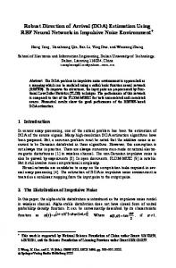
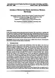
Fig.1: Structure of speed estimator using NN are using equation (5) to find out the back emf voltage independent of the motor speed (ωr) as in Adaptive Model block the current and the estimated speed (obtained from our ANN) are used for that. The error between these two blocks then is used to adjust the weights of the neurons in the speed estimator. The bigger error between the two back emf model outputs, the more correction in the weights is exerted. The structure of the ANN Speed Estimator is the well known structure of Jordan recurrent network [20] which is shown in Fig.2. The inputs are the voltage and current of the motor in the stationary αβ frame (four inputs: Vsα , Vsβ , isα , isβ) plus the output (estimated speed) of the previous step which is used as the extra input. The adjustment of the weights in hidden layer is achieved by using the error of back emf. Note that though the back emf is a vector, but as using the amplitude of it conduces to acceptable result, it’s used in order to simplify the calculation. Backpropagation method is used in this way, so the weight correction for the i → j connection is calculated from this equation [21]:
Hidden Layer Inputs
Output
− ωr Iemα L2m i sα + 2 Rr (6) R Ie i sβ − r mβ Lr Lr
Context Fig.1 illustrates the structure of the proposed speed estimator. In the Reference Model block we
ωˆ r
Fig.2: Structure of NN
2005 WSEAS Int. Conf. on DYNAMICAL SYSTEMS and CONTROL, Venice, Italy, November 2-4, 2005 (pp592-597)
Table 1 : Induction Motor Parameters
B
∆w ji (k ) = α∆w ji (k − 1) + η ji ∑ δ (j b ) (k ) y i(b ) (k ) b =1
(7) Or by naming the output for neuron i as oi it could be written as bellow [13]:
∆w ji (k ) = α∆w ji (k − 1) + ηδ j oi
(8)
To start the training the weights are initially randomize from 0.5 (these two recent parameters are obtained by try and error in several tests to have the best result. Theoretically they can take some amount between 0 and 1 with no exact formula [22]). After that, in each step the estimated speed is used in adaptive model and the error between two models would replace to repeat the calculation. So, the training is completely online (real-time) with no necessary pre-calculation.
Related Power
Pr
500 W
Line-Line Voltage
Vr
220 V
Related Torque
T
3.41 N m
Number of Poles
P
4
Stator Resistance
Rs
4.495 Ω
Rotor Resistance
Rr
5.365 Ω
Stator Indoctunce
Ls
165 mH
Rotor Inductance
Lr
162 mH
Magnetisting Inductance
Lm
149 mH
Rotor Moment of Inertia
J
.00095 Kg m 2
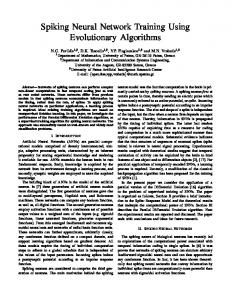
algorithm is shown in Fig.3. Real-time simulation technique is widely used nowadays by high-tech industries, particularly automotive and aeronautics industries (aircraft flight control, satellite control, etc), as the main tool for rapid prototyping of complex engineering systems in a cost-effective and secure manner, while reducing the time-to-market. RT-Lab uses Simulink as a front-end interface for editing graphic models in block-diagram format which are afterward used by this real-time plate-form to generate necessary CCodes for real-time simulations on parallel processors.
3 Real-Time Simulation Results The parameters of the induction motor used in this work are given below in Table 1. Real-Time digital simulation is carried out using RT-Lab in order to verify the accuracy of the estimation algorithm in addition to observing the response of the sensorless VC drive system. The block diagram of the sensorless Indirect FOC induction motor drive, incorporating the proposed NN speed estimation
+ Vdc − ω
*
* i ds
* Tem Indirect
ψ
* r
FOC
i
dq
* qs
ρ
abc
i
* as
i
* bs
i cs*
+ -
+
INVERTER
-
+
2h
2h
2h
-
ias ibs ics ωˆ
ANN Speed Estimator
αβ
abc
αβ
abc
IM
Fig.3: Block diagram of sensorless Indirect FOC Induction Motor Drive using NN
2005 WSEAS Int. Conf. on DYNAMICAL SYSTEMS and CONTROL, Venice, Italy, November 2-4, 2005 (pp592-597)
200 S p e e d (ra d / s )
150 100
S p e e d (ra d / s )
100
Estimated Speed
50 0 -50
0
0.5
1
1.5
2
0
0.5
1
1.5
2
0
0.5
1
1.5
2
2.5
3
3.5
4
4.5
5
2.5 3 Time (s)
3.5
4
4.5
5
10 0 -10
Estimated Speed
0
2.5
20
-20
Fig.5: Speed Estimation for Load Changes 3
3.5
4
4.5
5
20 E rro r (ra d / s )
Actual Speed
150
Actual Speed
50
-50
200
E rro r (ra d / s )
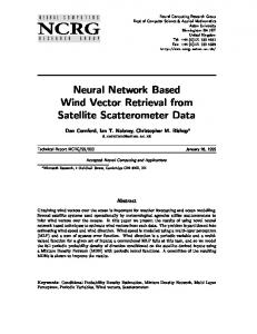
Simulation is carried out for different operating conditions of the motor drive to study the performance of the NN speed estimator. First, the machine is operated at no load. Fig.4 shows the speed, estimated speed and the speed estimation error for this operation. At 0.5 s the machine is accelerated to 150 rad/s and then, decelerated in steps to 120 rad/s, 50rad/s and 10rad/s at 2 s, 3 s and 4 s respectively. There is an error of less than 1% in the estimated speed in the steady states, but trying to decrease it (by changing the training parameters) causes some instability in the output.
10 0
The accuracy of estimation was found to be very good with a small error of less than 1% under steady state conditions. It is found that the NN speed estimator has good accuracies under both transient and steady state conditions, at high and low speeds and at no load and loaded conditions of the speed sensorless VC induction motor drive system.
-10 200
0.5
1
1.5
2
2.5 3 Time (s)
3.5
4
4.5
5
Fig.4: No-Load Speed Estimation Next, the performance of the estimator while the machine is loaded and unloaded is studied. The machine is accelerated to 150 rad/s at 0.5 s and full load is applied at 2 s and then, the load is fully removed at 3.5 s. The speed estimated speed and the speed estimation error are shown in Fig.5. It is observed that the estimated speed tracks the actual speed very well with a small error of less than 1% in steady states. Smaller changes in the load perform even a better result for sure. Finally, the performance of the fully loaded drive system at various operating speeds is studied. The fully loaded motor is started at 0.5 s to 150 rad/s and after the speed gets stable it is decelerated in steps to 75 rad/s at 2 s and finally to 10 rad/s at 3.5 s. The actual speed, estimated speed and the speed estimation error are shown in Fig. 6.
Estimated Speed
150 S p e e d (ra d / s )
0
100
Actual Speed
50 0 -50
0
0.5
1
1.5
2
0
0.5
1
1.5
2
2.5
3
3.5
4
4.5
5
2.5 3 Time (s)
3.5
4
4.5
5
20 E rro r (ra d / s )
-20
10 0 -10 -20
Fig.6: Full-Loaded Motor Speed Estimation
2005 WSEAS Int. Conf. on DYNAMICAL SYSTEMS and CONTROL, Venice, Italy, November 2-4, 2005 (pp592-597)
4 CONCLUSION In this paper, we have presented a speed estimation method using neural networks (NN) in a vector controlled (VC) induction motor drive. The proposed method uses a Jordan recurrent NN structure where training of the NN is done online using back-propagation algorithm. The method uses the back emf based MRAS where reference model is independent of speed and the adaptive model needs speed information which it obtains from the NN estimator. The flux based MRAS requires pure integration of sensed variables which leads to problems with initial conditions and drift. To avoid these problems, the pure integrator is replaced with a high gain lowpass filter which causes the instability of identification at low speed, which results to weak performance. As only differentiators exist in the used scheme, system has a very good performance even in low speeds as long as the stator resistance is known. Real-time digital simulation results show that the method is capable of accurate estimation under no load and loaded conditions of the drive, at high or low speeds of operation, and in both steady state and transient conditions. This achievement is considered to be an important contribution to sensorless operation of induction motor drives.
References: [1] F. Blaschke, The Principal of Field-Orientation as Applied to the New Transvector closedLoop Control System for Rotating-Field Machines, Siemens Review XXXIX, Vol.5, 1972, pp. 217-219. [2] K. Hasse, On the dynamics of speed control of a static ac drive with a squirrel-cage induction machine, PhD dissertation, Tech. Hochsch. Darmstadt, 1969. [3] C. Schauder, Adaptive speed Identification for Vector Control of Induction Motors without Rotational Transducers, IEEE Trans. Ind. App., Vol.28, No.5, 1992, pp. 1054-1061. [4] H. Tajima, Y. Hori, Speed Sensorless Field Orientation Control of the Induction Machine, IEEE Trans. Ind. App., Vol.29, No.1, 1993, pp. 175-180. [5] Fang-Zheng Peng, and Tadashi Fukao, Robust Speed Identification for Speed Sensorless Vector Control of Induction Motors, IEEE Trans. Ind. Appl., Vol.30, No.5, 1994, pp. 1234-1240.
[6] Y. R. Kim, S. K. Sul and M. H. Park, Speed Sensorless Vector Control of Induction Motor Using Extended Kalman Filter, IEEE Trans. Ind. Appl., Vol.30, No.5, 1994, pp. 1225-1233. [7] V. Comnac, M. Cernat, M. Cotorogea & I. Draghici, Sensorless Direct Torque and Stator Flux Control of Induction Machines Using an Extended Kalman Filter, Proc. IEEE Int. Conf. on Control Appl., Mexico, 2001, pp. 674-679. [8] X. Ma and Y. Gui, Extended Kalman Filter for Speed Sensorless DTC Based on DSP, Proc. 4th World Cong. on Intelligent Control and Automation, Shanghai, China, 2002, pp. 119122. [9] T. Du, P. Vas and F. Stronach, Design and Application of Extended Observers for Joint State and Parameter Estimation in High Performance AC Drives, Proc. IEE Elec. Power Appl. Vol.142, No.2, 1995, pp. 71-78. [10] M. Bodson, J. Chiasson and R. T. Novotnak, Nonlinear Speed Observer for High Performance Induction Motor Control, IEEE Trans. Ind. Elec., Vol.42, No.4, 1995, pp. 337343 [11] J. J. Liu, I. C. Kung and H. C. Chao, Speed Estimation of Induction Motor Using a NonLinear Identification Technique, Proc. National Sc. Council, ROC(A), Vol.25, No.2, 2001, pp. 107-114. [12] V. Pappano and B. Friedland, Speed Sensorless Observer for an Induction Machine, Proc. of the American Control Conf., Albuquerque, New Mexico, June 1997, pp. 3805-3806. [13] V. Pappano, S. E. Lyshevski and B. Friedland, Identification of Induction Motor Parameters, Proc. 37th IEEE Conf. on Decision and Control, Tampa, Florida USA, Dec. 1998, pp. 989-994. [14] S. H. Kim, T.S. Park, J. Y. Yoo and G. T. Park, Speed-Sensorless Vector Control of an Induction Motor Using Neural Network Speed Estimation, IEEE Trans. Ind. Elec., Vol.48, No.3, 2001, pp. 609-614. [15] D. Fodor, J. P. Six and D. Diana, Neural networks applied for induction motor speed sensorless estimation, in Proc. ISIE’95, 1995, pp. 181-186. [16] K. L. Shi, T. F. Chan, Y. K. Wong and S. L. Ho, Direct Self Control of Induction Motor Based on Neural Network, IEEE Trans. Ind. Appl., Vol.37, No.5, Sept./Oct. 2001. [17] R. M. Bharadwaj and A. G. Parlos, Neural State Filtering for Adaptive Induction Motor Speed Estimation, Mechanical Systems and Signal
2005 WSEAS Int. Conf. on DYNAMICAL SYSTEMS and CONTROL, Venice, Italy, November 2-4, 2005 (pp592-597)
Processing, Vol.17, No.5, Sept. 2003, pp. 903924. [18] B. Beliczynski and L. Grzesiak, Induction motor speed estimation: neural versus phenomenological model approach, Elsevier Science B. V., Neurorocomputing, Vol.43, 2002, pp. 17-36. [19] M. G. Simoes, B. K. Bose, Neural Network Based Estimation of Feedback Signals for a Vector Controlled Induction Motor Drive, IEEE Trans. Ind. Appl., Vol.31, No.3,
May/June 1995, pp. 620-629. [20] Jose C. Principle, Neil R. Euliano and W. C.urt Lefebvre, Neural and Adaptive Systems, John Wiley & Sons Inc., 2000, pp. 529-544. [21] Simon Haykin, Neural Networks, A Comprehension Foundation, Macmillan College Pub., 1994, p. 197. [22] K. S. Narendra and K. Parthasarathy, Identification and control of dynamical systems using neural networks, IEEE trans. Neural Networks, Vol.1, No.1 , Mar. 1990, pp. 4-27.