High Speed Neural Network Chip on PCI-Board W. Eppler 1, T. Fischer 1, H. Gemmeke1, T. Becher 2, G. Kock 2 1 Research Center Karlsruhe (FZK), POB 3640, 76021 Karlsruhe, Germany 2 INCO GmbH, Stöhrerstr. 17, 04347 Leipzig, Germany E-mail:
[email protected]
Abstract A novel neural chip SAND (Simple Applicable Neural Device) is described. It is highly usable for massive parallel neural network computations. The chip is optimized for a high input data rate (50 MHz, 16 bit data) at a very low cost basis. The performance of a single SAND chip is 200 MOPS due to four parallel 16 bit multipliers and 40 bit adders working in one clock cycle. The chip is able to implement feedforward neural networks with a maximum of 512 input neurons and three hidden layers. Kohonen feature maps and radial basis function networks may be also calculated. Up to four chips are implemented on a PCI-board for industrial applications and on a VME board for trigger analysis in particle physics.
1. Real-Time Applications Networks
with
Neural
The Research Center Karlsruhe (FZK), in collaboration with IMS, designed the neuro-chip SAND (Simple Applicable Neural Device) for industrial and physical real time applications. In the following some of these applications are introduced to show that there is need for a fast neural network computation. SAW-sensors. One application uses surface acoustic waves (SAW) to detect and analyze unknown gases. SAW devices have a large field of applications in the electronics of signal processing and therefore they advanced to an item of industrial mass production of microchips. In a modified form they can be used as highly sensitive detectors for gases or organic components in water: coated with a selective sorptive layer, they serve as a frequency determining element of an oscillator circuit. The mass change of the coating arising from the sorption of an analyte leads to a proportional shift of the oscillation frequency. For actual applications the SAW devices were coated with different polymers with a certain degree of selectivity towards different organic components. To perform a quantitative and qualitative analysis of organic
gases and their mixtures with polymers as sensitive membranes, it is necessary to use an array of several sensors with different coatings generating different responses towards a specific gaseous component and thus obtaining a typical response pattern towards a certain analyte. As the central component the analytical sensor system developed by the Institute of Instrumental Analysis of FZK contains an array of eight SAW resonators and one common reference oscillator for temperature compensation. They are mounted together in a compact monolithic housing. The obtained patterns of the sensor response are evaluated by using neural networks providing the required qualitative and quantitative determination of gases and gaseous mixtures. Multi-layer perceptrons are used to determine the proper gas ratios and the gas concentrations, respectively. These networks are coupled with radial basis function networks (RBF) to detect unknown gases. Metal oxide sensors. Another project determines gas concentrations with a resistor array of 40 metal oxide gas sensors. To allow a simultaneous and selective detection of mostly organic compounds in air, a gas sensor microsystem was developed at the Institute of Instrumental Analysis of FZK. For a simple, but highly sensitive detection of organic vapours semiconductor metal oxide detectors are used. The electrical conductivity of those materials is highly dependent on changes in the composition of gaseous atmospheres. At the moment the gas sensor microsystem consists of a silicon chip, sized 8mm x 9mm. This chip is equipped with 40 single sensing elements and two temperature sensors on the front side, plus 4 separate heating elements on the backside. A different sensibility of each sensor element is achieved by various gradient methods. There can be both a lateral temperature gradient over the 40 sensor elements, and a gradient in the thickness of the ceramic membrane. The resulting signal patterns allow a highly sensitive detection of single compounds in complex gaseous atmospheres. Multi-layer perceptrons are doing the analyzing task. Pipeline inspection. Neural networks are also used in pattern recognition tasks of pipeline crack detection. Oil
companies prefer non-destructive inspection in pipelines because of the lower costs compared to destructive testing. The prevention of impairments due to material flaws growing by the time, e.g. corrosion, is an ongoing challenge in pipeline operations. Any defect which affects integrity of the pipeline can lead to service disruptions and increases the risk of damage to the environment. A pipeline inspection forms the basis of an effective remedial and preventative maintenance program. The inspection tool is equipped with a large number of ultrasonic sensors mounted on a special sensor carrier. Each probe transmits ultrasound pulses perpendicular to the pipe wall and receives the reflections from the inner and outer pipe wall surface. The time of flight of each ultrasound pulse and echo is measured with high precision in order to determine the actual wall thickness and distance between probe and pipe wall. All the data is stored on disks and tapes which are evaluated off-line with statistical and neural pattern recognition tools. The on-line data compression and reduction from 100 TBytes to 20 GBytes is not enough and should be improved in near future. Multiple neural network chips may help to accept this challenge. Mammography. X-ray mammography is one of the most effective methods in diagnosis of breast cancer. The detection of grouped micro-calcifications is often the only early indicator of malignant structures within the tissue. Micro-calcifications are often very small (50 - 100 micron) and overlapped by other structures. An automatic computer assisted detection of microcalcifications may thus reduce the risk of misdetecting some micro-calcifications and lead to a more reliable diagnosis. Image convolution which will reveal calcifications is a very time consuming task and thus not feasible with todays microcomputers in real time. Several SAND chips speed up these convolutions. The nonlinear transfer function is applied to implement a decision threshold to mark regions containing microcalcifications. Particle physics. The exploitation of the range of γenergies between 10 and 300 GeV is of great importance and requires new experimental techniques and „intelligent“ methods of data analysis. The expected trigger rate of the Atmospheric Cherenkov Telescope (ACT) in the MAGIC project can be decreased considerably by using neural network hardware triggers. The trigger will provide reliable muon and hadron background rejection now available only off-line. The computing power of SAND is sufficient for the pattern recognition of Cherenkov images as the expected decision time did not exceed few of tenths of
microseconds. The training of the neural network is carried out with detailed simulations of Extensive Air Shower (EAS) traversing atmosphere and with the response of apparatus, including the noise in electronics. The method and obtained performance of pattern recognition will be shown. There is a variety of different applications each of them demanding for their own criteria an effective hardware solution.
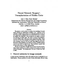
2. Neural Network Basics For most of these applications a feedforward network is used. In feedforward networks neurons are arranged in layers without back-loops. There are no connections between neurons of the same layer. The basic element of a neural network is an artificial neuron described by n x i = f ∑ wij ⋅ o j + Θ j =1
(1)
where wij are the connection weights from neurons j to neuron i. The input activities oj are multiplied with the connection weights, accumulated and transfered by a nonlinear activation function to the output activities xi (Fig. 1). O1 wi1 O2 O3
wi2
∑
wi3
On
Xi
win
Fig. 1 : Model of an artificial neuron
If all neurons of one layer are regarded (Fig. 2), the function of the complete layer can be described as a matrix/vector multiplication x = f (W * o) , (2) where o is the input vector and W the weight matrix which keeps all connection weights between two related layers. The sigmoidal function
f (x) =
1 1 + e −αx
(3)
is mostly used as the activation function in feedforward networks. To increase calculation speed of a neural network, neurons have to work in parallel. On the other hand a high flexibility concerning the structure of neural networks should be ensured. To grant both demands, only neurons within the same layer are processed in parallel, whereas the various layers are processed
sequentially. The architecture of the chips and the design criteria of the system are described. flow of data O1
X1
O2
X2
...
...
On
Xm
Fig. 2 : Part of a feedforward network
3. Some Criteria for Neural Hardware Evaluation With different methods it is possible to reduce the computation efforts while executing neural networks. One example is an implementation of the non-linear sigmoidal activation function in a lookup table. Memory access can be done simpler and faster (less than 20 ns) than the computation of an exponential function with multiplications and additions. In the same direction it is possible to reduce the network size by eliminating useless neurons and weights near to zero. When executing the network they need not to be computed. With some applications such methods will not improve the performance. A general acceleration is only possible with parallel processing. Following criteria are considered to be crucial for choosing the right hardware: 1.both applicable as a PC-board and stand-alone 2. cheap 3. few peripheral devices 4. sufficient precision (at least 16 bit) The PC-board is necessary to provide a user friendly programming tool for development. The stand-alone solution facilitates the use of the hardware acceleration in applications independent of the platform of development. The second criterion is decisive for industrial applications. This criterion applies, e.g., to the gas analyzers introduced in the former section. Point 3 is crucial for micro-systems with small space and very low power consumption. In second level trigger of particle physics experiments (e.g. calorimeters) a sufficient precision is needed because of the high dynamic range of signals. There are especially three neuro chips available fulfilling partly the given selection criteria: the MA16 of
Siemens [1], CNAPS of Adaptive Solutions [3] and ETANN of Intel [6]. MA16 mainly fails criteria 1 and 3. In the meantime SYNAPSE with one MA16 is available as PC-board [10]. To make a stand-alone solution many other chips and a micro-controller are necessary. CNAPS and ETANN fail criterion 4. CNAPS is working with 8 bit accuracy, or 16 bit with less than half the rate. Even worse, the analog ETANN computes with approximately 6 bit accuracy. Sometimes poor accuracy may be compensated by non-linear data transformations. But for on-chip training of the neural network a minimal data length of 16 bits seems to be necessary to find the global optimum. In the following sections the alternative neuro chip is introduced to meet better the presented four criteria.
4. Design Considerations of SAND SAND is a cascadable, systolic processor array designed for fast processing of neural networks. The neurochip SAND may be mapped on multi-layer perceptrons (MLP), radial basis function networks (RBF) and Kohonen’s self organized feature maps (SOM). Due to these most common neural network types, SAND covers about 75% of all important applications. This estimation is result of an analysis of 154 applications found in the literature. In the following the idea of the organization of the neural processor is given for the feedforward network, mostly used. Looking at the matrix/vector multiplication introduced in the first section, it is obvious, that the weight matrix can be separated into several row vectors, see Fig.3. These vectors can be multiplied in parallel with the activation vector o. Each row i of the weight matrix corresponds to the weights connecting n transmitter neurons with one receiver neuron. If a layer consists of m neurons, a systolic array with m parallel working processing elements is required to get full use of a parallel architecture. One important disadvantage of this solution is the need of m weight memories. This fact causes high costs in peripheral components and a huge area for busses. We can think of another solution where only one weight memory is used. This single memory must be read at high speed (m times higher compared to the previous solution), not possible with available memories. A solution of this principal problem can be obtained by adjusting the number of input activities to the number of weights. Then a maximal usage of hardware can be ensured. This demand can be granted if several input patterns are used instead of one. The activation vector is replaced by a matrix which consists of m columns. In the example in Fig. 4 with m=4 it is shown, how incoming
activities are multiplied with the corresponding weights. Values which are already transfered into SAND are marked with a grey shadow. The four processors are symbolized by a circle, a pentagon, an octagon, and a square, respectively. It can easily be seen that four processors compute 16 multiplications within 4 cycles. In every cycle only one weight and one activity have to be transfered. vector of input activities
1 2 ...
weightmatrix line vector 1
n
processing-unit
line vector 2 ...
1
MULT
ADD
MULT
ADD
MULT
ADD
...
n
line vector m LookupTable f(x) vector of output activities
1 2 ...
m
Fig. 3 : Architecture of a matrix/vector multiplier
m=4 parallel processor elements
1. cycle m=4 patterns w11 w12 w13
o11
o13
o14
o21
o22
o23
o24
w31 w32 w33
o31
o32
o33
o34
w41 w42 w43 2. cycle
m=4 parallel processor elements
o12
w21 w22 w23
m=4 patterns
w11 w12 w13
o11
o12
o13
o14
w21 w22 w23
o21
o22
o23
o24
w31 w32 w33
o31
o32
o33
o34
w41 w42 w43
m=4 parallel processor elements
3. cycle m=4 patterns w11 w12 w13
o11
o12
o13
o14
w21 w22 w23
o21
o22
o23
o24
w31 w32 w33
o31
o32
o33
o34
w41 w42 w43
m=4 parallel processor elements
4. cycle w11 w12 w13
m=4 patterns o11
o12
o13
o14
w21 w22 w23
o21
o22
o23
o24
w31 w32 w33
o31
o32
o33
o34
w41 w42 w43
Fig. 4 : Example of processed data (m=4 patterns)
5. Architecture of SAND Based on the design considerations of the previous chapter, the architecture of SAND was developed. Looking again at the example of Fig. 4 one can see that each of the processor elements (PE) is working four cycles with the same weight. Every fourth cycle the weight is updated so there is a continuous flow of weights on the weight bus. In the considered period of four cycles four activities are loaded into SAND’s processor elements. These activities are transfered over registers from one PE to the next. There is a continuous flow of data on both the activity and on the weight bus. Due to the method data and commands are handled the architecture of SAND is a systolic processor array. In Fig. 5 the architecture of SAND is shown, which consists of four parallel processing elements each equiped with an ALU and an auto-cut module. The ALU in Fig. 5 is used for the multiplication of vectors within the matrix/matrix multiplication. Due to the accumulation of activities the width of words grow from 16 bit up to 40 bit, if the number of input neurons is limited to 512. To be compatible with external memories (16 bit), and with the width of activities outside the chip (16 bit), a window of 16 bit must be cut out of 40 bit. The position of this window may be influenced by a user-defined selection of an appropriate weight range. The cut is done in the autocut module which automatically checks if an over/underflow occurs. To minimize the error caused by the cut, an automatic adaption of the accuracy is performed in a second step. In some cases it is important to find extremal values in the flow of output activities. Therefore, a postprocessing module is used which can work in two modes: search for a maximum or a minimum. The appropriate activation function f(x) is realized outside the chip with a lookup table. Some types of neural networks require both a linear function f(x)=x and a non-linear function like the sigmoidal function. Therefore SAND has two outputs: one for addresses of the lookup table and one for linear data. For the calculation of expression (1) a multiplier and an adder are needed to perform a fast multiplication of vectors. To increase speed both elements are placed within a pipeline. As a first step input activities are multiplied with corresponding weights and then added to previous values. Due to the fact that four patterns are processed, four accumulation registers are required within the PEs. For some neural networks it is also necessary to calculate the Euklidian distance between two vectors. Therefore SAND’s ALU is equipped with an additional adder, which is also placed in the pipeline.
This feature is essentially used for Kohonen Feature Maps or Radial Basis Function Networks (RBF). activties
weights
16
16 R16
R16
R16
R16
R16
16
16
ADD 16
16
R16
ALU
40
PE 1
PE 2
PE 3
PE 4
Auto-Cut 16 R16 R16 R16 R16
Registerbank
16
16
16
16
Post-Processing Min-Max-Search 16
address
16
data
Fig. 5 : Block structure of SAND
6. Structure and Operation of PCI BOARD For acceleration of neural simulations, a PCI board was designed which can work with up to four SAND chips running at 50 MHz. The performance can be scaled from 200 MOPS (one SAND processor) up to 800 MOPS (four SAND processors). The board contains several memory blocks which store incoming activities, inter-
mediate results and final results in three FIFO chips. Weights are stored in distributed memories, attached to SAND processors. Incoming activities are multiplied with corresponding weights and accumulated within the SAND processors. The calculation of the activation function is done with a look-up table implemented within a fast SRAM external to SAND. The flow of data to and from the board is controlled by the data stream controller (DSC) which also holds the configuration of a neural network. Control of SAND processors, access to memories, and initialization of weight memories and look-up table are performed by a sequencer (SEQ). The exchange of data between host and PCI-board is asynchronous. A simple protocol synchronizes both communication sites. On the PCI-board two components are involved to handle the PCI-interface: the PCIcontroller AMCC5593 and the data stream controller (DSC) being implemented by a field programmable gate array (FPGA). Another controller, the sequencer (SEQ), produces outputs controlling the SAND chip. Inside the PCI-controller there are three mailbox registers (see Fig. 6). The first one receives commands from the host. They are called „DSC commands“ in the following as this mailbox register is read and interpreted by the DSC. The output of the DSC are SEQ instructions being interpreted by the sequencer. There is a possibility for the host directly sending SEQ instructions to the sequencer. DSC only passes them through without interpretation. This mode is useful when debugging and testing the SAND chip. One rather complicated command, the SandLoadNet command, also uses this facility to break down its complex task into simpler ones. The second and third mailbox registers contain the status of network execution and the hardware configuration of SAND chips. If the second mailbox register is written by the SAND hardware, an interrupt to the host results. The interrupt service routine of the host has to lock all interrupts and then to read the PCI interrupt register and the status register of the mailbox. At the end of the service routine the interrupt flag of the PCI board has to be reset and the interrupts have to be allowed again. The PCI interface transfers commands and data, respectively. Commands are sent to the mailbox or to the DSC, the data is sent to the input queue (FIFO) of SAND. This FIFO contains at most two complete data sets. One data set consists of four subsequent input patterns for the neural network. When SAND is working with the current data set, at the same time a second set may be read into the FIFO.
• • • • •
PCI Interface
Mailbox
Cmd
Data
SEQ Instructions
DSC Commands
FIFO
DSC SEQ Instructions SEQ
SAND
LUT
WGT
Fig. 6 : Command (thin lines) and data stream (thick lines) on PCI board
7. Driver Interface of PCI Board The programming and operation of the SAND chip requires several layers of description (see Fig. 7). At the top level there is a set of driver routines written in C. There are functions like • • • • •
SandTest() SandLoadLUT(RealFunc func) SandLoadMLP(RealFunc func) SandApplyNet(double* input) SandReadNet(double* input)
CreateLUT() NormalizeActivities() NormalizeWeights() NormalizeResults() CreateNetConfig()
In general a driver routine consists of multiple DSC commands. These commands are sent directly to the data stream controller (DSC) that controls the signals to the PCI controller on the one side and the signals to the sequencer on the other side. The function SandLoadMLP(...) e.g. includes eight different actions. Among them is the memory allocation for weights, biases and network configuration, normalization to 16 bit fixedpoint values, download of weight and bias values and of network configuration and, finally, the release of memory space. Some DSC commands are: • LdWgtRAM(Opmode, Blocksize, Pos) • RdWgtRAM(ChipSelect, Blocksize, First) • LdLUT(Opmode, Blocksize, First) • InitNetConfig(Blocksize) • CompNet(DBGmode, Blocksize) 31
0
- x x 0 0 1 0 1 0 - - x x x x x x x x x x - - x x x - - - - - -
Opmode: Action: 10: Test here: 11: Init Write
Object: here: WgtRAM
Blocksize: (in 16 bit words)
Pos of Pattern: 100: End (of layer) 010: Begin (of layer) 001: First (of network)
Fig. 8 : Example of DSC command User C-Routines C-Library with Driver Utilities
Driver Routines
DSC Commands
The DSC uses these DSC commands to generate SEQ instructions for the sequencer that is controlling the SAND chip. The SEQ instructions are of the following form (e.g. for the multiply and accumulate instruction (MUL_ACC):
SEQ Instructions 31
0
0 1 0 0 x x y y - x - - y y y y x - - y y y y x x x x x x x x x
PCI Interface
Fig. 7 : Different layers of driver routines
The meaning of most of these functions is selfexplanatory. LUT means the look-up table defining the linear or non-linear output function of a neuron. MLP means ‘multi-layer perceptron’. Other possible neural network types are RBF (radial basis functions) and SOM (self organized maps of Kohonen). The driver routines need some utilities to normalize activities and weights or to create a look-up table from a function. Examples are:
Opcode: No of Pos of MUL_ SAND neuron: ACC chips 10: first 01: last
first cut DGB/last No of hidden mode flag bias layer neuron s
No of nodes in previous layer
Fig. 9 : Example of SEQ instruction
Other SEQ instructions are: • SQ_ACC • LD_FIFO
- square accumulate - load FIFO
• RD_LUT - read look-up table • DEF_LAYER - define network layer • GET_HW_CONFIG - get hardware configuration
The sequencer (SEQ) interpretes these instructions and produces proper timed signals (a 34 bit wide control bus) to control the SAND chips.
8. Technical Data and Performance of SAND SAND is manufactured in a 0.8µm CMOS process, using a sea-of-gates technology with almost 50K Gates. The packaging of SAND is a PGA with 144 signal-pins. SAND has four parallel working processing elements (PE) on one chip, each equipped with a 16 bit fixed point multiplier and a 40 bit adder in a pipeline. Data coming from the input is passed through clocked registers from one PE to the next. To make use of the parallel structure, four events of activities are processed in one cycle. In this way a matrix/vector multiplication is replaced by a matrix/matrix multiplication, insuring a permanent and full use of the parallel processing units and yielding 200 MOPS per chip operation speed at a cycle time of 20 ns. The non-linear activation function is calculated by the use of a free programmable look-up table allowing for a maximum of flexibility. A controller chip, the memories, the lookup table and the SAND chip are arranged as a fixed modular unit guaranteeing the tight timing for up to 50 MHz operation. There are two well known applications of digital neural network processors in second level triggers: CNAPS[3] in H1 [2] and MA16 [1] in WA92 [4], see Tab. 1. The neural processor module based on SAND demonstrates throughput similar to the CNAPS-board and successfully competes with it when the data acquisition system is equipped with an event buffer. Moreover, the module allows processing of higher accuracy input activities. The SAND processor module shows higher throughput than the trigger module based on MA-16 due to the simultaneous processing of four events and the higher clock frequency of SAND board.
9. MiND Software Design Software Components. The PCI neuro-board is part of the system MiND (Multipurpose integrated Neural Device), which is a flexible and extendible tool for developing neural network applications. This section describes the MiND software components and, specifically, the software layers provided for the neuroboard. At the end, the specific advantages of the MiND system are pointed out. In Fig. 10 the architecture of MiND is presented. The MiND manager administrates a pool of simulators, each of which has a comfortable graphical user interface and can be used to create, train, and apply networks. Typically, a simulator supports a specific network type. For standard network types like MLP, RBF, SOM, Hopfield, etc., MiND provides a number of predefined simulators. However, a user can extend the system by self-defined ones. This flexibility is achieved by the fact, that each simulator is constituted by two abstract definitions: (1) a network definition written in the neural network description language CONNECT, and (2) an interface definition. Writing or modifying simulators means to write or modify such definitions. The interface definition is a C++ script which uses abstract GUI classes and a network class generated from a CONNECT network definition.
Fig. 10 Architecture of the MiND system Tab. 1 : Comparison of existing MA16 and CNAPS data with SAND (from simulation) ANN input computation latency structure activities time time CNAPS 8bit/20MHz 8µs un64x64x1 known SAND 16-bit/40MHz 5.1µs 27µs MA-16 16-bit/8MHz 5.5µs 8µs 16x5x1 SAND 16-bit/40MHz 0.5µs 3.6µs
The CONNECT Language. The CONNECT language [11] is based on a generic connectionist model. Each CONNECT specification consists of a number of unit type definitions followed by a network type definition. In addition, procedures, functions, and relations can be defined. Unit and network types are defined in an object oriented style, relations and functions are defined in a functional style. Relations are
collections of pairs of indices used for connecting (and disconnecting) layers of units. A unit type is defined from a „local“ point of view. Fanout signals, input and output vectors describe the I/O behaviour of a unit, local variables are used to provide for local memory (e.g. for weights), and unit activation procedures are used to define the possible activations of units. On the other hand, a network type is defined from a „global“ point of view. It consists of a number of layers, which are (multidimensional) arrays of units, other variables, network activation procedures, and an initialisation part, which can be considered as a special network activation procedure. Connect and disconnect statements can be used to dynamically establish and modify topologies. During the execution of these statements, I/O entities of units are (dis)related with each other. Using a dot notation, a network activation procedure can execute a certain unit activation procedure for all units of a layer. Similarly, a certain I/O entity or variable defined in a unit type can be accessed simultaneously for all units of a layer. The CONNECT compiler translates the specification into a C++ class, the methods of which correspond to the network activation procedures of the CONNECT definition. This class can be instantiated (e.g. BP_Net net(60,12,60)), and used by calling it’s methods (e.g. net.Forward()). Note that, as CONNECT supports the definition of complex relations, dynamic creation and deletion of connections, shared variables, etc., not only standard networks, but also hierarchical networks, networks with dynamic topologies, local receptive fields, recurrent networks, and others, can be specified. GUI Classes. The MiND system provides GUI classes for menus, dialogue boxes, panels, monitors, and network graphs. An interface definition script typically consists of three parts. In the declaration part, the graphical objects constituting the interface, a number of event procedures, and an instance of the generated C++ network class are declared. In the initialisation part, graphical objects are constructed (e.g. panel.Line( „Hidden size:“, hsz )) and related with each other and with the event procedures (e.g. menu.Bind( „Run“, proc_run )). Finally, in the implementation part, event procedures are defined. Typically, each event procedure consists of a few lines of code only, as it uses the powerful methods of generated C++ network classes and MiND GUI classes. Developing Custom Applications. After having developed a network with one of the simulators administrated by the MiND manager one might wish to „export“ this network for using it as a component of an „external“ system. This process is supported by the
possibility to export the C++ network classes generated from the CONNECT network definitions. The methods of the generated network classes reflect the functionality of the original CONNECT definition. Therefore, an exported network not only can be applied. If necessary, a custom application can further train a network etc. Note that in some cases the development of (prototype) applications might be even simpler, and may consist of modifying the interface of a given simulator only. This is done by modifying the corresponding interface definition script. Software Layers. Fig. 11 shows the software layers for the PCI neuro-board. The driver’s C interface offers direct access to the functionality of the MiND PCI neuroboard. From a user’s point of view it is a simple to user software interface and hides all hardware specific aspects. In addition, for all networks supported by the neuro-chip, the corresponding simulators can be used to exploit the PCI neuro-board via a graphical user interface. This is achieved by adapting the generated C++ network classes on the base of the driver’s C interface. Note that a C++ network class using the neuroboard can be exported like any other C++ network class.
10. Conclusion Depending on the application several design criteria for ANN chips have to be met. These are partly different, especially in respect to the size and the type of the neural network. SAND performs feedforward networks, Kohonen feature maps and radial basis functions with comparable speed. The central processing unit of the chip was designed in a way that only few additional devices are required compared to previous designs. To facilitate a stand-alone operation of SAND, the neuron activities are buffered. Because of the modular structure, performance improvements may be achieved by adding more processing elements. Future developments of general purpose microprocessors like pentium P55C from INTEL, K6 from AMD, M2 from Cyrix and others have to be regarded carefully. Their MMX-instructions and the use of parallel integer units on chip enable these devices to very fast matrix multiplications. Up to now the independent parallel transfer of data is a problem so that they cannot compete with the performance of SAND. Because of many restrictions the internal pipeline organization is not appropriate for the fast computation of neural networks. Other processors (from MIPS with MDMX-instructions) or the digital signal processor TMS320C80 from TI aim to the same direction dealing with similar problems. But in near future this may change.
References [1] U. Ramacher et al., ”Design of a First Generation Neurocomputer“, in VLSI-Design of Neural Networks, eds. U. Ramacher and U. Rückert, Kluwer Academic Publishers, 1991 [2] D. Goldnez et al., Proceedings of 4th International Workshop on software Engineering, Artificial Intelligence and Expert Systems for High Energy and Nuclear Physics, April 3 - 8, 1995, Pisa, Italy, pp. 333-340 [3] Adaptive Solutions, CNAPS product Information, 1995 [4] C. Baldanza et al., NIM A 376 (1996) 411 and NIM A 373(1996) 261 [5] P.Cennini et al., NIM A 356 (1995) 507 Fig. 11 Software Layers of MiND PCI neuro-board
The SAND chip is produced by IMS1, the MiND PCIboard with four SAND chips is coming from INCO, Leipzig. Faster versions using full-custom design and supporting a fast hardware learning features are under development. Like many other neural network development systems, MiND offers predefined components for standard neural algorithms, and graphical user interfaces to work with them. The specific characteristics of MiND are the option to employ the PCI neuro-board, and it’s flexibility and extendibility, which is based on the fact that simulators are described by a CONNECT network definition and a GUI definition. These definitions introduce a level of abstraction which enables a user to modify neural algorithms or graphical interfaces or to create own ones. Also, the possibility to export the C++ network classes generated by the CONNECT compiler is a powerful means for developing custom applications. The flexibility and extendibility of other neural network development tools is more restricted or require a user to have detailed knowledge about internal data structures or large libraries of C or C++ modules [12,13].
[6] C.S. Lindsey and B. Denby : „A study of the Intel ETANN VLSI Neural Network for an Electron Isolation Trigger“, 1992, internal CDF Note CDF/DOC/CDF/Public/1850 [7] C. Kiesling et al.: „A level-2 Neural Network Trigger for the H1 Experiment at HERA“, KHEP 1994 [8] T.Fischer, H.Gemmeke, W.Eppler, A.Menchikov, S.Neusser: „Novel digital hardware for trigger applications in particle physics“ in Proc. of 2nd Workshop on Electronics for LHC Experiments, Balatonfüred, Hungary 1996 [9] Front Panel Data Port Specification (VITA 17-199x, Rev.1.1)
[10] Siemens Corp., „Neurocomputers and Tools“, SYNAPSE 2-Homepage at http://www.snat.de/welcome.htm“ [11] G.Kock, N.B. Serbedzija: Artificial Neural Networks: From Compact Descriptions to C++. Proc. of the Int. Conf. on Artificial Neural Networks (1994) 1372-1375 [12] G.Kock, N.B. Serbedzija: Simulation of Artificial Neural Networks. System Analysis - Modelling Simulation (SAMS) 27 (1996) 15-59 [13] J.M.J. Murre: Neurosimulators. The Handbook of Brain Theory and Neural Networks (M.A. Arbib, Ed.), MIT Press (1995) 634-639
The MiND® project is supported by the SMWA under PT-Nr. 2553. MiND® is a registered trademark of INCO Systeme GmbH 1
IMS, Allmandring 30a, D-70569 Stuttgart, Germany