Sep 29, 2009 - ... Linder,2 Gholamreza Rashedi,1 Takehito Yokoyama,3 and Asle Sudbø2 ...... 97, 147002 (2006); J. Linder, M. Grønsleth, and A. Sudbø,. Phys ...
Spin-polarized Josephson current in S|F|S junctions with inhomogeneous magnetization Mohammad Alidoust,1 Jacob Linder,2 Gholamreza Rashedi,1 Takehito Yokoyama,3 and Asle Sudbø2
arXiv:0909.5427v1 [cond-mat.supr-con] 29 Sep 2009
1
Department of Physics, Faculty of Sciences, University of Isfahan, Hezar Jerib Avenue, Isfahan 81746-73441, Iran 2 Department of Physics, Norwegian University of Science and Technology, N-7491 Trondheim, Norway 3 Department of Applied Physics, University of Tokyo, Tokyo 113-8656, Japan (Dated: Received September 29, 2009) We study numerically the properties of spin- and charge-transport in a current-biased nanoscale diffusive superconductor|ferromagnet|superconductor junction when the magnetization texture is non-uniform. Specifically, we incorporate the presence of a Bloch/Neel domain walls and conical ferromagnetism, including the role of spin-active interfaces. The superconducting leads are assumed to be of the conventional s-wave type. In particular, we investigate how the 0-π transition is influenced by the inhomogeneous magnetization texture and focus on the particular case where the charge-current vanishes while the spin-current is non-zero. In the case of a Bloch/Neel domain-wall, the spin-current can be seen only for one component of the spin polarization, whereas in the case of conical ferromagnetism the spin-current has the three components. This is in contrast to a scenario with a homogeneous exchange field, where the spin-current vanishes completely. We explain all of these results in terms of the interplay between the triplet anomalous Green’s function induced in the ferromagnetic region and the local direction of the magnetization vector in the ferromagnet. Interestingly, we find that the spin-current exhibits discontinuous jumps at the 0–π transition points of the critical charge-current. This is seen both in the presence of a domain wall and for conical ferromagnetism. We explain this result in terms of the different symmetry obeyed by the current-phase relation when comparing the charge- and spin-current. Specifically, we find that whereas the charge-current obeys the well-known relation Ic (φ) = −Ic (2π − φ), the spin-current satisfies Is (φ) = Is (2π − φ), where φ is the superconducting phase difference. PACS numbers: 74.78.Na
I.
INTRODUCTION
Because of the interesting phenomena that superconductor|ferromagnet|superconductor (S|F|S) structures exhibit, including their potential applications in spintronics1,2 and quantum computing3,4,5,6 , this field of research is presently studied extensively.6,7 Usual electronic devices are based on the properties of flowing electrons through circuits, whereas spintronic devices are based on direction and number of flowing spins. In many spintronics devices, like magnetic tunnelling junctions, spin polarized currents are generated when an imbalance between spin up and down carriers occurs. This imbalance can arise e.g. by using magnetic materials or applying a magnetic field. The discovery of the giant magnetoresistance (GMR) effect8 today forms the basis of the leading technology for information storage by magnetic disc drives. Spin coupling and its advantageous high speeds at very low powers9 of these devices promise applications for logic and storage applications.10,11,12 The possibility of a π-state in a S|F|S systems was predicted theoretically in Refs.13,14 and has been observed experimentally.15 Near such a transition point, the junction ground state energy has two minima versus φ at φ = 0 and φ = π. The coexistence of stable and metastable 0 and π states in the transition zone can produce two flux peaks for one external quantum flux in superconducting quantum interference device (SQUID)-like geometry, and renders the system a qubit.16 The characteristic length of the ferromagnetic layer where the first 0–π transition occurs is of the order of the magnetic coherence length ξF . In the dirty limit, that is achievable in most of the experimentally studied S|F|S struc-
p tures. Here, ξF is given by D/h where D denotes the diffusion constant and h is the magnitude of ferromagnetic exchange field. Therefore, the experimental observation of such 0-π transitions in nanoscale devices requires a low exchange energy h. Such conditions were achieved using weak ferromagnetic CuNi or PdNi alloys. The experimental observations of the critical charge-current oscillations shows such 0π transitions as a function of the ferromagnet thickness and temperature.15,17,18,19 The consequence of the exchange splitting at the Fermi level20 is that the Cooper pairs wave function shows damped oscillations in the ferromagnet, resulting in the appearance of the well known π-state in S|F|S systems.13 In contrast to the usual 0-state in superconductor-normal metalsuperconductor junctions, the phase shift equal to π across the junction in the ground state reverses the direction of the supercurrent,15 and considerably changes the density of states (DOS) in the F metal.17 The π-states can also be observed in nonmagnetic junctions of high-Tc superconductors21 and in non-equilibrium nanoscale superconducting structures.22 In the ballistic limit, the transport properties of a S|F|S junction can be understood on a microscopic level in terms of Andreev bound-states.23 The 0–π transition is then due to the spin dependence of the Andreev bound states.24 Because of the averaging of the quasiclassical Green’s function25 over momentum directions, the relevant equations simplify in the dirty transport regime. This averaging of Green’s function can be understood by noting that in the presence of impurities and scattering centers, the direction of motion of electrons are random and physical quantities should be averaged over all directions. This averaging is valid as long as the mean free path of the diffusive layer is much smaller than length scales of thepsystem that are superconducting coherence length ξS = D/∆0 and the decay length of Cooper
2 p pairs wave functions inside ferromagnet ξF = D/h, where ∆0 is the superconducting order parameter. The chargecurrent Ic (φ) and the local DOS are two principle quantities that are strongly influenced by the proximity effect. These two quantities were studied for various geometries by using of quasiclassical Green’s function in clean and dirty limits in several works, e.g.26,27,28,29,30,31,32,33,34,35,36 . Up to now, the majority of works studying S|F|S junctions have considered a homogeneous exchange field in the ferromagnet, including half-metallic ferromagnets.37,38,39,40,41 In the presence of inhomogeneous magnetization textures, several new effects have been predicted in the literature including the possibility of a long-range triplet component. Such an inhomogeneous magnetization texture may be created artificially by setting up several layers of ferromagnets with misaligned magnetizations.42,43,44,45,46,47 Alternatively, inhomogeneous magnetization may arise naturally in the presence of domain walls or non-trivial patterns for the local ferromagnetic moment. An example of the latter is the conical ferromagnet Ho. Very recently, two theoretical studies have predicted qualitatively new effects in S|F and S|F|S hybrid structures where F is a conical ferromagnet48,49 . Due to the inhomogeneous nature of the magnetization in Ho, the spinproperties of the proximity-induced superconducting correlations are expected to undergo a qualitative change compared to the case of homogeneous ferromagnetism. Such changes may also be expected in the domain-wall case. A more realistic modeling of hybrid structures involving superconductors and ferromagnets demands that such non-trivial magnetization textures and also the spin-dependent properties of the interface regions50,51 are taken into account seriously. It was recently shown that the latter may induce qualitatively new features in the local DOS of S|F layers52 and S|N layers with magnetic interfaces53 . Another consequence of inhomogeneous magnetization, be it in the form of multiple misaligned layers or intrinsic nonuniformity within a single ferromagnetic layer, is that the Josephson current should become spin-polarized. This has been noted by several authors in the context of superconductors coexisting with helimagnetic or spiral magnetic order56,57 as well as ferromagnetic superconductors54,55 . However, the spin-polarization of the Josephson current has not been studied in the arguably simplest case of a single ferromagnetic layer with inhomogeneous magnetization contacted by two conventional s-wave superconductors. To this end, we develop in this paper a model for an S|F|S junction where both inhomogeneous magnetization and spinactive interfaces are incorporated, and then proceed to solve the problem numerically. More specifically, we will investigate variations of spin- and charge- currents versus changing of the thickness of F layer dF for a hybrid S|F|S structure with s-wave superconductors. We find that a spin-current flows through the junction whenever the magnetization is inhomogeneous, and that it features discontinuous jumps whenever the junction undergoes a 0–π transition. We compare these variations for three types of magnetization textures i.e., homogeneous, domain wall, and a conical exchange field. We also show that for certain values of dF , the critical charge-current
vanishes whereas a pure spin-current flows through the system. Moreover, we demonstrate how it is possible to obtain a pure spin-current by tuning the phase difference between the superconductors.
II.
THEORY
To investigate the behavior of the ferromagnetic Josephson junction, we employ a full numerical solution of the quasiclassical equations of superconductivity25 in the diffusive limit58 , which allows us to access the full proximity effect59 regime. Importantly, we also take into account the spin-dependent phase-shifts (spin-DIPS) microscopically60 that are present at the superconductor|ferromagnet interfaces. For the purpose of stable and efficient numerical calculations, it is convenient to employ the Ricatti-parametrization of the Green’s function as follows:61,62,63 � � N (1 − γ˜ γ) 2N γ gˆ = (1) ˜ γ˜ ˜ (−1 + γ˜ γ) . 2N N Here, gˆ2 = ˆ1 since ˜ = (1 + γ˜ γ)−1 . N = (1 + γ˜ γ )−1 N
(2)
We use . . . for 2 × 2 matrices and . ˆ. . for 4 × 4 matrices. In order to calculate the Green’s function gˆ, we need to solve the Usadel equation58 with appropriate boundary conditions at x = −dF /2 and x = dF /2. We pintroduce the superconducting coherence length as ξS = DS /∆0 . Following the notation of Ref.48 , the Usadel equation reads D∂(ˆ g ∂ˆ g ) + ı[εˆ ρ3 + diag[h · σ, (h · σ)T ], gˆ] = 0,
(3)
and we employ the following realistic boundary conditions for all our computations in this paper:50 2ζdF gˆ∂ˆ g = [ˆ gBCS (φ), gˆ] + ı(GS /GT )[diag(τ3 , τ3 ), gˆ] (4) ∂ at x = −dF /2. Here, ∂ ≡ ∂x and we defined ζ = RB /RF as the ratio between the resistance of the barrier region and the resistance in the ferromagnetic film. The barrier conductance is given by GT , whereas the parameter GS describes the spinDIPS taking place at the F side of the interface where the magnetization is assumed to parallel to the z-axis. The boundary ˜S ) condition at x = dF /2 is obtained by letting GS → (−G and gˆBCS (φ) → [−ˆ gBCS (−φ)] in Eq. (4), where
γ BCS (φ) = ıτ2 s/(1 + c)eıφ/2 , γ˜ BCS (φ) = γ BCS (φ)e−ıφ .
(5)
˜ S is allowed to be different from GS in general. Above, G For instance, if the exchange field has opposite direction at the two interfaces due to the presence of a domain wall, one ˜ S = −GS . The total superconducting phase differfinds G ence is φ, and we have defined s = sinh(ϑ), c = cosh(ϑ) with ϑ = atanh(∆0 /ε) using ∆0 as the superconducting gap.
3 Note that we use the bulk solution in the superconducting region, which is a good approximation when assuming that the superconducting region is much less disordered than the ferromagnet and when the interface transparency is small, as considered here. We use units such that ~ = kB = 1. The values of GS and GT may be calculated explicitly from a microscopic model, which allows one to characterize the j transmission {tjn,σ } and reflection amplitudes {rn,σ } on the j ∈ {S, F } side. Under the assumption of tunnel contacts and a weak ferromagnet, one obtains with a Dirac-like barrier model50,51,60 X X� 4τnS � (6) GT = GQ Tn , GS = 2GQ ρF n − Tn n n P upon defining Tn = σ |tSn,σ |2 and F F ∗ S S S ∗ ρF n = Im{rn,↑ (rn,↓ ) }, τn = Im{tn,↑ (tn,↓ ) }.
(7)
For simplicity, we assume that the interface is characterized by N identical scattering channels. Omitting the subscript ’n’, the scattering coefficients are obtained as: rσF = (kσF − kσS − ıkσS Zσ )/Dσ , q tSσ = 2 kσS kσF /Dσ , with the definitions Dσ = kσS + kσF + ıkσS Zσ and p p kσS = 2mS µS , kσF = 2mF (µF + σh).
(8) and (9)
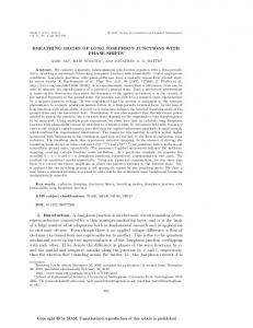
Here, Zσ = Z0 + σZS is the spin-dependent barrier potential. Defining the polarization P = h/µF in the ferromagnet and the polarization ν = ZS /Z0 for the barrier, we will set P = ν. In this paper we will consider three types of inhomogeneous magnetic textures: Bloch, N´eel and a conical structure. These structures are all different from a homogenous magnetic texture. The first two types of magnetic textures are assumed to be located at the center of the F layer. The Bloch model is demonstrated by h = h(cos θˆ y + sin θˆ z ) and its structure is shown in Fig. 1. Similarly, the N´eel model reads h = h(cos θˆ x + sin θˆ z ) where we defined θ as follows63 : θ = − arctan(x/dW ).
FIG. 1: (Color online) i) The S|F|S junction with Bloch domain wall of ferromagnet and ii) with conical type of ferromagnet. The magnetization texture for the Neel wall is obtained by replacing the x-component of the magnetization with an y-component in case i). The blue arrows show the magnetic moments in F layer. The magnetic moment for Bloch/Neel domain wall has two components and for conical type has three components.
(10)
Here, dW is the width of domain wall and we assumed that the center of F layer is located at the origin, i.e, x = 0 as shown in Fig. 1. For the conical case, we adopt a model where the magnetic moment rotates on the surface of a cone with defined apex angle α and turning angle β. This structure is shown in Fig.1 (α and β will determine the kind of material in use). If we assume that the distances of interatomic layers are a,64 the spiral variation in the exchange field can be written as h = h(cos αˆ x + sin α[sin(βx/a)ˆ y + cos(βx/a)ˆ z ]). (11) To characterize the transport properties of the system, we define the normalized charge and spin current densities according to: Z ∞ n � ∂ˇ Ic g �K o = d˜ ε Tr ρˆ3 gˇ (12) , Ic,0 ∂x ˜ 0
Isz = Is,0
∞
Z 0
n � ∂ˇ g �K o , d˜ ε Tr ρˆ3 τˆ3 gˇ ∂x ˜
(13)
respectively, where ε˜ = ε/∆0 , x ˜ = x/dF , and ρˆ3 = diag(1, 1, −1, −1). Here Ic and Isz are the charge- and the z-component of the spin-current flowing in the x ˆ-direction, respectively. The normalization constants are: Ic,0 =
N0 eD∆0 ~Ic,0 , , Is,0 = 8dF 2e
(14)
where N0 is the normal state DOS per spin and D is the diffusion constant. In general, the spin-current for other components of spin polarization j ∈ {x, y, z} is given as: � � Z ∞ n � ∂ˇ τj 0 Isj g �K o = d˜ ε Tr ρˆ3 νˆj gˇ , νˆj = . 0 τj ∗ Is,0 ∂x ˜ 0 (15) Above, ρˆi , τˆi , and τi are Pauli matrices that are defined in the appendix C and the reader may consult Appendix B for the derivation of the expression for Isj /Is,0 . Under the assumption of an equilibrium situation, the Keldysh block of Green’s function reads: gˆK = [ˆ g R − gˆA ] tanh(βε/2),
(16)
where gˆR and gˆA = −(ρˆ3 gˆR ρˆ3 ) are Retarded and Advanced blocks of gˇ respectively, and β = 1/T is inverse temperature. III.
RESULTS AND DISCUSSION
We now present our main results of this paper, namely a study of how the critical currents depend on the thickness dF
4
A.
Critical currents vs. thickness dF for homogeneous exchange field
First, we consider how the charge- and spin-currents are influenced by changing the thickness of F layer dF in the homogeneous magnetic texture case. We fix the temperature at
0.07 -4
x 10
0.06 10 5
Icc/Ic,0
cc c,0
0.05
I /I
of the junction in the presence of homogeneous and inhomogeneous exchange field and spin-active interfaces. In order to focus on a realistic experimental setup, we choose the junction parameters as follows. For a weak, diffusive ferromagnetic alloy such as Pdx Ni1−x , the exchange field h/∆0 is tunable by means of the doping level x to take values in the range meV to tens of meV. Here, we will fix h/∆0 = 15, which typically places the exchange field h in the range 15-25 meV. The thickness dF of the junction is allowed to vary in the range dF /ξS ∈ [0.5, 1.2], which is equivalent to 9 − 21.6 nm for a superconducting coherence length of ξS = 18 nm as can be obtained for e.g. Nb. This range of layer thicknesses dF are experimentally feasible.65 The ratio of GS /GT is calculated according to the microscopic expressions given in the previous section only for uniform and domain wall exchange fields because we will set GS = 0 for the conical ferromagnet. We choose µF = 1 eV and µS = 10 eV for the Fermi level in the ferromagnet and superconductor, respectively, and consider a relatively low barrier transparency of Z0 = 3. The electron mass mF and mS in both the F and S regions is taken to be the bare one (' 0.5 MeV). Any change in effective mass translates into an effective barrier resistance due to the Fermiwavevector mismatch, which thus is captured by the parameter Zσ . The interface region is assumed to exhibit a much higher electrical resistance than in the bulk of the ferromagnet, and we set ζ = RB /RF = 4. For more stability in our computations we used the Ricatti parametrization and also inserted a small imaginary part δ = 5 × 10⁻³ ∆0 in the quasiparticle energy ε, effectively modeling inelastic scattering. A considerable amount of CPU-time was put into the calculations of the current, as we solved for a fine mesh of both quasiparticle energies ε and phase differences φ for each value of the width dF . As will be discussed in detail below, we find that for S|F|S structures with spin-singlet s-wave superconducting leads, a spin-current exists only for domain wall structures and conical type of the ferromagnet layer, whereas it vanishes completely in the case of a homogeneous exchange field. Both the charge- and spin-current are evaluated in the middle of the F region, x = 0. The charge-current is conserved throughout the system, and its magnitude is thus independent of x. The spincurrent, on the other hand, is not conserved and in fact suffers a depletion close to the S|F interfaces and vanishes completely in the superconducting regions. The critical charge-current is given by Icc =maxφ {Ic (φ)}, and the phase giving the critical current may be denoted φc . We define the critical spin-current as Ics =Is (φc ), which means that we are effectively considering the spin-polarization of the critical charge-current, which should be the most sensible choice physically in a currentbiased scenario. Note that this is different from the maximum value of the spin-current as a function of φ.
0.04
0
0.03 -5
0.02 1.04
0.01 0 0.5
0.6
0.7
0.8
0.9
1.06 dF/ξS
1
1.08
1.1
1.2
dF/ξS
FIG. 2: (Color online) The variation of the normalized critical charge-current versus the thickness of a homogeneous F layer. The inset panel zooms in on the behavior near the 0-π transition. As long as the exchange field is constant, we find that the spin-current Is vanishes.
T /Tc = 0.2, and use the microscopic expression for spinDIPS Gφ at the two boundaries. The result is shown in the Fig. 2. The critical charge-current in the region of dF from 0.5ξS to 1.2ξS vanishes at one point. This point is the first 0-π transition point. We found that, for all strengths of the exchange field and spin-DIPS, the spin-current Is is zero. Unlike the case of spin-triplet superconductors, we can not see any spincurrent even for x ˆ and yˆ directions of spin polarization66,67 . In fact, one can confirm this finding analytically for all components of spin polarization at least for linearized Usadel equation and transparent boundaries. The reason for the vanishing spin-current will become clear from the discussion in the following section, when noting that only the Sz = 0 oddfrequency triplet and even-frequency singlet components are induced by the proximity effect in the ferromagnetic region.
B.
Critical currents vs. thickness dF for Bloch and N´eel domain walls
We now turn our attention to the first example of a nontrivial magnetization texture in the ferromagnet, namely the scenario of a Bloch or Neel domain wall. We use the same values for h and T as in the previous section, and set the domain wall width dW to dW /dF = 0.5 and assume that it is centered in the ferromagnet. Although the domain-wall structure dictates that the magnetization is not fully directed along the z-axis at the interfaces, we have verified numerically that the influence of the spin-DIPS parameter GS is negligible for our choice of parameters, such that we still can use the boundary conditions in Sec. II. The results of the variation of the normalized critical spinand charge-currents vs. dF /ξS are shown in the Fig. 3 , considering here a Bloch wall texture. Contrary to the homogeneous case considered in the previous section, we now see
5 the Neel domain wall case leads to the result that only a spinpolarization in the y-direction is present. Since we are evaluating the spin-current in the middle of the F region, the zcomponent of the local exchange field is absent there. In that case, hSi should equal to zero according to our argument above. The reason for why a finite spin-current is nevertheless obtained must be attributed to a lag between the f and h vectors, such that they do not follow each other exactly. One would expect that for a slower variation of the local exchange field, the lag would decrease.
Icc/Ic,0
0.01
-3 x 10 3
0.005
2 1 0 0.6
0
0.7
I /I
cs c,0
0.04 0.03 0.02 0.01 0 0.5
0.6
0.7
0.8
0.9
1
1.1
dF/ξS
C. FIG. 3: (Color online) The variations of normalized critical spinand charge-currents vs. increasing the thickness dF of F layer with a Bloch domain wall structure.
that a finite spin-current flows through the system. For this type of magnetization texture, we note that the spin-current only exists for one component of the spin polarization: the x ˆcomponent. Only one component of the spin-current would be present also in the Neel domain wall case, as we shall explain below. The spin-current features a discontinuous jump at the same value of the thickness where the charge-current undergoes a 0–π transition, namely dF /ξS ' 0.6. For this value of thickness the spin-current has a rapid variation. We have checked numerically with a very high resolution of dF (a step of 5 × 10⁻⁴ for dF /ξS ) that this result does not pertain to noise or any error. For this type of magnetization texture, we also note that a spin-current only exists for one component of the spin polarization: the x ˆ-component. We will explain the reason for both the presence of such jumps in the spin-current and the polarization properties later. We now explain why only one component of the spinpolarization is present both in the Bloch and Neel domain wall case. In order to understand the reason for this, it is instructive to consider the interplay between the triplet anomalous Green’s function f , given by f=
hf − f i(f↓ + f↑ ) f↑↓ + f↓↑ i ↓ ↑ ,− , 2 2 2
(17)
and the local direction of the exchange field h. In S|F proximity structures, f tends to align as much as possible with h. For a homogeneous exchange field h in the z-direction, one thus obtains that only the Sz = 0 opposite-spin pairing triplet component ft = f z is present, as is well-known. Consider now the Bloch domain wall case. The f -vector then contains only y- and z-components. Now, the spin expectation value of the Cooper pair is provided by hSi ∝ ı(f × f ∗ ),
(18)
and we immediately infer that only a spin-polarization in the x-direction will be present. A similar line of reasoning for
Critical currents vs. thickness dF for conical type of magnetization texture
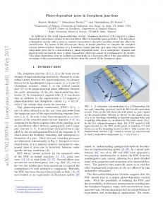
Finally, we turn our attention to the conical model for magnetization, relevant to Ho. For simplicity, we set the GS = 0 at the two boundaries at −dF /2 and d/ 2. The distance between the atomic layers a is equal to 0.02dF , α = 4π/9, and rotating angle β = π/6 per interatomic layer. These values of a, α and β are chosen based on the actual lattice parameters of Ho. The result of the investigation of how the critical spinand charge-currents vary as a function of dF /ξS is shown in the Fig. 4. In this case, we see a qualitatively new behavior for the charge-current as compared to the previous two subsections where we treated a homogeneous exchange field and a domain-wall ferromagnet, respectively. In Fig. 4, one observes a superimposed pattern of fast oscillations on top of the usual 0–π oscillations, which are slower. This is in agreement with the very recent work by Halasz et al.49 , who also reported the generation of rapid oscillations on top of the conventional 0–π transitions of the current in the weak-proximity effect regime. These faster oscillations pertain to the inhomogeneous magnetization texture considered here, although they are not seen in the domain-wall case. This fact indicates that they are sensitive to the precise form of the magnetization structure in the ferromagnet, and that they do not appear simply as a result of a general inhomogeneity. As can be seen in the Fig. 4, the critical-charge current has five local minima, out of which three are 0–π transition points. In Fig. 4, the first dotted horizontal line indictates a minima which is irrelevant to a 0–π transition, whereas the three following dotted lines indicate minima which correspond to such transitions. The last local minima is located near dF /ξS = 1.2 and is not indicated by a dotted line in Fig. 4. This is in contrast to the homogeneous and domain wall case, where only one 0–π transition point is seen in the range of dF considered here. As for the spin-current, the behavior is similar to the Bloch wall structure, with a rapid variation at the transition point. As mentioned previously, we have investigated these discontinuous jumps of the spin-current with a very high resolution for dF to ensure that do not stem from numerical errors or noise. We now proceed to an explanation for this effect.
6 -3
0.05
10 8 6 4 2
-3
1
x 10
0.06
6
0.04
4 2
Ixs / Is,0
Icc/Ic,0
0.1
x 10
-3
x 10
0
0 -2 0.58 0.6 0.62
0.9 0.92 0.94
0 0.1
0.02 0
-1
-0.02
-2
-0.002
0
0 -0.05
Iys / Is,0
Ic / Ic,0
Ixcs/Is,0
0.05
-3
0.15
-4 0.1
-0.005
Izs / Is,0
Iycs/Is,0
-0.004 -0.006
-0.1 0
-5 -0.01 0.1
0 -0.05
Izcs/Is,0
-6 0
0.6
0.7
0.8
0.9
1
1.1
1.2
dF/ξS
FIG. 4: (Color online) Plot of the normalized critical spin- and charge-current vs. the normalized thickness dF of the F layer for a conical type of magnetization texture. All three components of the spin polarization have a considerable magnitude in the entire range of dF considered here.
D.
0.5
1.0
0
φ /π
0
-0.1 0.5
0.05
0.5
1.0
φ/π
FIG. 5: (Color online) Plot of the current-phase relation for the charge- and spin-currents. We are considering a conical magnetization texture, and the curves range from dF /ξS = 0.7655 to 0.7725 in steps of 1 × 10⁻³ in the charge-current panel. For the spin-current panels, the variation of the current-phase relation upon changing dF is negligible and we give results only for dF /ξS = 0.7725. Note that the critical spin-current nevertheless varies strongly with dF near the transition points as shown in Fig. 4, since the critical phase displays a strong dependence on dF in this regime.
Origin of the discontinuous jumps in the spin-current
In order to understand the mechanism behind the discontinuous jumps of the spin-current near the 0–π transition of the junction, we revert briefly to the original definition of the critical spin-current. It is defined as Is (φc ) where φc is the value of the superconducting phase difference which gives the maximum (absolute) value of the charge-current. In effect, the critical spin-current is the spin-polarization of the critical charge-current, which is distinct from the maximum value of the spin-current. We now consider in detail the current-phase relation for both charge- and spin-transport near the transition point located at dF /ξS ' 0.772 (see Fig. 4). The result for the current-phase relation is shown in Fig. 5, where we consider several values of dF near the transition point. From bottom to top, they range from dF /ξS = 0.7655 to 0.7725 in steps of 1 × 10⁻³ . A key point is that we have verified numerically that the charge-current is antisymmetric with respect to φ = π whereas the spin-current is symmetric around this value. More specifically, whereas Ic (φ) = −Ic (2π − φ)
(19)
we find numerically that the spin-current satisfies Is (φ) = Is (2π − φ)
(20)
This is consistent with the finding of Ref.66 where transport between spin-triplet superconductors has been investigated. As a result, it suffices to restrict our attention to the range φ ∈ [0, π]. Next, we note that the charge-current is nearly sinusoidal to begin with (bottom curves of Fig. 5). Upon increasing dF , and thus approaching the transition point, higher
harmonics in the current-phase relation become more protrudent for the charge-current. However, the spin-current remains virtually unafffected by an increase in dF , and we plot the result only for dF /ξS = 0.7725. Upon increasing dF , the critical phase φc moves away from π/2 to lower values due to the presence of higher harmonics in the current-phase relation. At the transition point, the phase jumps in a discontinuous manner to φc > π/2 (dotted arrow in Fig. 5). Now, the charge-current has a similar magnitude (in absolute-value) for this new value of φc . The spin-current, on the other hand, has a different symmetry with respect to φ as seen in Fig. 5, and varies less rapidly with dF . Therefore, the spin-polarization of the current makes a discontinuous jump at the transition point.
IV.
SUMMARY
In summary, we have considered the transport of charge and spin in a nanoscale S|F|S Josephson junction when the magnetization texture is inhomogeneous in the ferromagnetic layer. More specifically, we have investigated how charge and spin Josephson currents are affected by the presence of Bloch/Neel domain walls and conical ferromagnetism, including also the spin-active properties of the interfaces. We find that a spin-current flows through the junction whenever the magnetization is inhomogeneous, and that it features discontinuous jumps whenever the junction undergoes a 0–π transition. In the case of a Bloch/Neel domain-wall, the spincurrent can be seen only for one component of the spin polarization (the component perpendicular to both the local direc-
7 tion of the exchange field and that of its derivative), whereas in the case of conical ferromagnetism the spin-current has three components. For a homogeneous exchange field, the spincurrent vanishes. We explain the polarization properties of the spin-current by considering interplay between the triplet anomalous Green’s functions induced in the ferromagnetic region and the local direction of the magnetization vector in the ferromagnet. Moreover, we show how the discontinuous jumps in the spin-current stem from the different symmetries for the current-phase relation when comparing the chargeand spin-current. While the charge-current obeys the wellknown relation Ic (φ) = −Ic (2π − φ), the spin-current satisfies Is (φ) = Is (2π−φ), where φ is the superconducting phase difference. Our results open up new perspectives for applications in superspintronics by exploiting Josephson junctions with non-homogeneous ferromagnets.
mechanical expression for the expectation value of the spincurrent: hj S (r)i =
1 hIm{Ψ† (r)∇r diag(σ, σ ∗ )Ψ(r)}i, 2m
(B1)
with a fermion operator basis Ψ given as Ψ† (r) = (ψ↑† (r), ψ↓† (r), ψ↑ (r), ψ↓ (r)).
(B2)
Above, σ is the Pauli matrix vector. It should be noted that the spin-current j S is a tensor since it has a flow-direction in real space in addition to a polarization in spin-space. For clarity, we consider in what follows the σ2 -component corresponding ˆ -direction, as an example. We then to the polarization in the y get from Eq. (B1) [using that Im{ız} = Re{z} for a complex number z] 1 Re{−hψ↑† (r)∇r ψ↓ (r)i + hψ↓† (r)∇r ψ↑ (r)i 2m + hψ↑ (r)∇r ψ↓† (r)i − hψ↓ (r)∇r ψ↑† (r)i} 1 lim (∇r − ∇r0 )[hψ↑† (r)ψ↓ (r 0 )i = 4m r→r0 − hψ↓† (r)ψ↑ (r 0 )i + hψ↓ (r)ψ↑† (r 0 )i
hj yS (r)i = Acknowledgments
J.L. thanks I. B. Sperstad for helpful discussions. J.L. and A.S. were supported by the Research Council of Norway, Grants No. 158518/432 and No. 158547/431 (NANOMAT), and Grant No. 167498/V30 (STORFORSK). T.Y. acknowledges support by JSPS.
APPENDIX A: USEFUL RELATIONS FOR THE GREEN’S FUNCTION
− hψ↑ (r)ψ↓† (r 0 )i].
(B3)
Using the notation of Ref.68 , we define the following representation for the Keldysh Green’s function: � � D E X ˆ K (r, r 0 ) = −ı (ˆ ρ3 )mj [Ψ(r)j , Ψ† (r 0 )n ]− . G mn
j
(B4)
By introducing the auxiliary quantities ˜N ˜, ˜ = −N ˜D ∂x N = −N DN , ∂x N
(A1)
(A2)
we find that the matrix derivative of the Green’s function ∂x gˆR has the following components: γ )N DN , (∂x gˆR )11 = −DN − (1 − γ˜ R ˜ ˜D ˜N ˜, (∂x gˆ )12 = 2(∂x γ)N − 2γ N (∂x gˆR )21 = 2(∂x γ˜ )N − 2˜ γ N DN , R ˜N ˜ + (1 − γ˜ γ)N ˜D ˜N ˜ (∂x gˆ )22 = D
1 1 † hψ↑ (r)ψ↓ (r 0 )i + hψ↑† (r)ψ↓ (r 0 )i 2 2 1 1 † 0 = − hψ↓ (r )ψ↑ (r)i + hψ↑† (r)ψ↓ (r 0 )i. 2 2 (B5)
hψ↑† (r)ψ↓ (r 0 )i =
where we have defined ˜ = (∂x γ˜ )γ + γ˜ (∂x γ), D = (∂x γ)˜ γ + γ(∂x γ˜ ), D
It then follows from anticommutation that e.g. :
(A3)
The indices above refer to particle-hole space, and each of the above elements is thus a 2 × 2 matrix in spin-space.
APPENDIX B: QUASICLASSICAL EQUATION FOR THE SPIN-CURRENT
We here show how the matrix structure in the analytical expression Eq. (15) for the spin-current is obtained in the quasiclassical approximation. The starting point is the quantum
In this way, we can rewrite the last lines of Eq. (B3) as: � � 1 ˆ K (r, r 0 ) hj yS (r)i = lim0 (∇r − ∇r0 )[ı G r→r 8m � � � � 21 K 0 K 0 ˆ ˆ − ı G (r, r ) − ı G (r, r ) 34 � �12 K 0 ˆ (r, r ) ] +ı G 43
1 =− lim (∇r − ∇r0 )Tr{ˆ ρ3 8m r→r0 ˆ K (r, r 0 )}. × diag(τ2 , τ2 ∗ ) × G
(B6)
For the x and z-components, one replaces τ2 with τ1 and τ3 , respectively. APPENDIX C: PAULI MATRICES
The Pauli matrices that are used in this paper are
8
�
� � � � � 0 1 0 −ı 1 0 , τ2 = , τ3 = , 1 0 ı 0 0 −1 � � � � � � τ 0 1 0 1 0 1= , τˆi = i , , ˆ 1= 0 1 0 τi 0 1 � � � � � � 0 τ1 0 −ıτ1 1 0 ρˆ1 = , ρˆ2 = , ρˆ3 = . τ1 0 ıτ1 0 0 −1 (C1) τ1 =
1
2 3
4
5
6
7 8
9
10
11
12 13
14
15
16
17
18
19
20
21 22
23
24 25
S. A. Wolf, D. D. Awschalom, R. A. Buhrman, J. M. Daughton, S. von Molnar, M. L. Roukes, A. Y. Chtchelkanova, D. M. Treger , Science 294, 1488 (2001). G. A. Prinz, Science 282, 1660 (1998). I. Zutic, J. Fabian, and S. D. Sarma, Rev. Mod. Phys. 76, 323 (2004). L. B. Ioffe, V. B. Geshkenbein, M. V. Feigelman, A. L. Fauchere and G. Blatter, Nature (London) 398, 679 (1999). L. B. Ioffe, M. V. Feigelman, A. Ioselevich, D. Ivanov, M.Troyer, and G. Blatter, Nature (London) 415, 503 (2002). A. G. Golubov, M. Yu. Kupriyanov, and E. llichev, Rev. Mod. Phys. 76, 411 (2004). A. I. Buzdin, Rev. Mod. Phys. 77, 935 (2005). M. N. Baibich, J. M. Broto, A. Fert, F. Nguyen Van Dau, F. Petroff, P. Etienne, G. Creuzet, A. Friederich, and J. Chazelas, Phys. Rev. Lett. 61, 2472 (1988). J. M. Kikkawa and D. D. Awschalom, Nature (London) 397, 139 (1999). E. R. Mucciolo, C. Chamon, and C. M. Marcus, Phys. Rev. Lett. 89, 146802 (2002). M. Governale, F. Taddei, and R. Fazio, Phys. Rev. B 68, 155324 (2003). B. Wang, J. Wang, and H. Guo, Phys. Rev. B 67, 092408 (2003). L. N. Bulaevskii, V. V. Kuzii, and A. A. Sobyanin, Pis’ma Zh. Eksp. Teor. Fiz. 25, 314 (1977) [ JETP Lett. 25, 290 (1977)]. A. I. Buzdin, L. N. Bulaevskii, and S. V. Panyukov, Pis’ma Zh. Eksp. Teor. Fiz. 35, 147 (1982) [ JETP Lett. 35, 178 (1982)]. V. V. Ryazanov, V. A. Oboznov, A. Yu. Rusanov, A. V. Veretennikov, A. A. Golubov, and J. Aarts, Phys. Rev. Lett. 86, 2427 (2001). Z. Radovi´c, L. Dobrosavljevi´c-Gruji´c, and B. Vujiˇci´c, Phys. Rev. B 63, 214512 (2001). T. Kontos, M. Aprili, J. Lesueur, and X. Grison, Phys. Rev. Lett. 86, 304 (2001); T. Kontos, M. Aprili, J. Lesueur, F. Genet, B. Stephanidis, and R. Boursier, Phys. Rev. Lett. 89, 137007 (2002). V. V. Ryazanov, V. A. Oboznov, A. S. Prokofiev, V. V. Bolginov, and A. K. Feofanov, J. Low Temp. Phys. 136, 385 (2004). V. A. Oboznov, V. V. Bolginov, A. K. Feofanov, V. V. Ryazanov,and A. I. Buzdin, Phys. Rev. Lett. 96, 197003 (2006). E. A. Demler, G. B. Arnold, and M. R. Beasley, Phys. Rev. B 55,15174 (1997). D. J. van Harlingen, Rev. Mod. Phys. 67, 515 (1995). J. J. A. Baselmans, T. T. Heikkil¨a, B. J. van Wees, and T. M. Klapwijk, Phys. Rev. Lett. 89, 207002 (2002); J. J. A. Baselmans, A. F. Morpurgo, B. J. van Wees, and T. M. Klapwijk, Nature (London) 397, 43 (1999). A. F. Andreev, Zh. Eksp. Teor. Fiz. 46, 1823 (1964) [Sov. Phys. JETP 19, 1228 (1964)]. Y. Tanaka and S. Kashiwaya, Physica C 274, 357 (1997). J. W. Serene and D. Rainer, Phys. Rep. 101, 221 (1983).
26
27
28
29
30
31
32
33
34
35 36
37
38
39
40 41
42
43
A. A. Golubov, M. Yu. Kupriyanov, and Ya. V. Fominov, Pis’ma ´ Zh. Eksp. Teor. Fiz. 75, 223 (2002) [JETP Lett. 75, 190 (2002)]. F. S. Bergeret, A. F. Volkov, and K. B. Efetov, Phys. Rev. B 64, 134506 (2001); F. Bergeret, A. F. Volkov, and K. B. Efetov, Phys. Rev. B 68, 064513 (2003); A. F. Volkov, F. S. Bergeret, and K. B. Efetov, Phys. Rev. Lett. 90, 117006 (2003). M. Zareyan, W. Belzig, and Yu. V. Nazarov, Phys. Rev. Lett. 86, 308 (2001). G. Mohammadkhani and M. Zareyan, Phys. Rev. B 73, 134503 (2006) J. Linder and A. Sudbø, Phys. Rev. B 75, 134509 (2007); J. Linder and A. Sudbø, Phys. Rev. B 76, 214508 (2007). T. Yokoyama, Y. Tanaka, and A. Golubov, Phys. Rev. B 72, 052512 (2005); Phys. Rev. B 73, 094501 (2006); Phys. Rev. B 75, 134510 (2007); T. Yokoyama, Y. Tanaka, A. A. Golubov, and Y. Asano, Phys. Rev. B 73, 140504(R) (2006); T. Yokoyama, Y. Sawa, Y. Tanaka, and A. A. Golubov, Phys. Rev. B 75, 020502(R) (2007); T. Yokoyama, Y. Tanaka, and A. A. Golubov, Phys. Rev. B 75, 094514 (2007); Y. Sawa, T. Yokoyama, Y. Tanaka, and A. A. Golubov, Phys. Rev. B 75, 134508 (2007) J. Linder, T. Yokoyama, and A. Sudbø, Phys. Rev. B 77, 174507 (2008). K. Halterman and O. T. Valls, Phys. Rev. B 72, 060514 (2005); K. Halterman, P. H. Barsic, and O. T. Valls, Phys. Rev. Lett. 99, 127002 (2007); P. H. Barsic and O. T. Valls, Phys. Rev. B 79, 014502 (2009). T. L¨ofwander, T. Champel, and M. Eschrig, Phys. Rev. B 75, 014512 (2007); J. Kopu, M. Eschrig, J. C. Cuevas, and M. Fogelstr¨om, Phys. Rev. B 69, 094501 (2004); T. L¨ofwander, T. Champel, J. Durst, and M. Eschrig, Phys. Rev. Lett. 95, 187003 (2005); T. Champel, T. L¨ofwander, and M. Eschrig, Phys. Rev. Lett. 100, 077003 (2008). Ya. V. Fominov, N. M. Chtchelkatchev, and A. A. Golubov, Phys. Rev. B 66, 014507 (2002); Ya. V. Fominov, A. F. Volkov, and K. B. Efetov, Phys. Rev. B 75, 104509 (2007) M. Fogelstr¨om, Phys. Rev. B 62, 11812 (2000). G. Annunziata, M. Cuoco, C. Noce, A. Romano, and P. Gentile, Phys. Rev. B 80, 012503 (2009) M. Eschrig, J. Kopu, J. C. Cuevas, and G. Sch¨on, Phys. Rev. Lett. 90, 137003 (2003). Y. Asano, Y. Tanaka, and A. A. Golubov, Phys. Rev. Lett. 98, 107002 (2007). S. Takahashi, S. Hikino, M. Mori, J. Martinek, and S. Maekawa, Phys. Rev. Lett. 99, 057003 (2007). M. Eschrig and T. L¨ofwander, Nat. Phys. 4, 138 (2008). R. Grein, M. Eschrig, G. Metalidis, and Gerd Sch¨on, Phys. Rev. Lett. 102 227005 (2009). Yu. S. Barash, I. V. Bobkova, and T. Kopp, Phys. Rev. B 66, 140503 (2002). Z. Pajovi´c, M. Bozovi´c, Z. Radovi´c, J. Cayssol, and A. Buzdin, Phys. Rev. B 74, 184509 (2006)
9 44 45 46
47 48
49
50
51 52 53
54
55 56 57
58 59 60 61
62 63
64
65
66
67 68
M. Houzet and A. Buzdin, Phys. Rev. B 76, 060504 (2007). B. Crouzy, S. Tollis, D. Ivanov, Phys. Rev. B 75, 054503 (2007). I. B. Sperstad, J. Linder, and A. Sudbø, Phys. Rev. B 78, 104509 (2008). Z. Popovi´c and Z. Radovi´c, arXiv:0907.2042. J. Linder, T. Yokoyama, and A. Sudbø, Phys. Rev. B 79, 054523 (2009). G. B. Halsz, J. W. A. Robinson, J. F. Annett, and M. G. Blamire, Phys. Rev. B 79, 224505 (2009). D. Huertas-Hernando, Yu. V. Nazarov, and W. Belzig, Phys. Rev. Lett. 88, 047003 (2002); D. Huertas-Hernando, Yu. V. Nazarov, and W. Belzig, arXiv:cond-mat/0204116. A. Cottet and W. Belzig, Phys. Rev. B 72, 180503 (2005). A. Cottet and J. Linder, Phys. Rev. B 79, 054518 (2009). J. Linder, T. Yokoyama, A. Sudbø, and M. Eschrig, Phys. Rev. Lett. 102, 107008 (2009). M. Grønsleth, J. Linder, J.-M. Børven, and A. Sudbø, Phys. Rev. Lett. 97, 147002 (2006); J. Linder, M. Grønsleth, and A. Sudbø, Phys. Rev. B 75, 024508 (2007). Y. Zhao and R. Shen, Phys. Rev. B 73, 214511 (2006). M. L. Kulic and I. M. Kulic, Phys. Rev. B 63, 104503 (2001). I. Eremin, F. S. Nogueira, and R.-J. Tarento, Phys. Rev. B 73, 054507 (2006). K. Usadel, Phys. Rev. Lett. 25, 507 (1970). W. L. McMillan, Phys. Rev. 175, 537 (1968). A. Cottet, Phys. Rev. B 76, 224505 (2007). J. C. Hammer, J. C. Cuevas, F. S. Bergeret, and W. Belzig, Phys. Rev. B 76, 064514 (2007). N. Schopohl and K. Maki, Phys. Rev. B 52, 490 (1995). Alexander Konstandin, Juha Kopu, and Matthias Eschrig, Phys. Rev. B 72, 140501 (2005). I. Sosnin, H. Cho, V. T. Petrashov, and A. F. Volkov, Phys. Rev. Lett. 96, 157002 (2006). V. A. Oboznov, V. V. Bolginov, A. K. Feofanov, V. V. Ryazanov, and A. I. Buzdin, Phys. Rev. Lett. 96, 197003 (2006). G. Rashedi, and Yu.A. Kolesnichenko, Physica C 31-37, 451 (2007). Y. Asano, Phys. Rev. B 74, 220501(R) (2006). J. P. Morten, M. Sc. thesis, Norwegian University of Science and Technology (2003).