Jan 5, 2010 - arXiv:0907.0277v2 [cond-mat.supr-con] 5 Jan 2010. Theory of vortex ... 4 JST, TRIP, 5 Sambancho Chiyoda-ku, Tokyo 102-0075, Japan.
Theory of vortex structure in Josephson junctions with multiple tunneling channels: Vortex enlargement as a probe of ±s-wave superconductors Yukihiro Ota,1, 3 Masahiko Machida,1, 3, 4 Tomio Koyama,2, 3 and Hideki Matsumoto2, 3
arXiv:0907.0277v2 [cond-mat.supr-con] 5 Jan 2010
1
CCSE, Japan Atomic Energy Agency, 6-9-3 Higashi-Ueno Taito-ku, Tokyo 110-0015, Japan 2 Institute for Materials Research, Tohoku University, 2-1-1 Katahira Aoba-ku, Sendai 980-8577, Japan 3 CREST(JST), 4-1-8 Honcho, Kawaguchi, Saitama 332-0012, Japan 4 JST, TRIP, 5 Sambancho Chiyoda-ku, Tokyo 102-0075, Japan (Dated: January 6, 2010)
We theoretically study Josephson vortex structures in Josephson junctions which have multiple tunneling channels caused by multiple superconducting gaps. Deriving “coupled sine-Gordon equations” from the free energy taking account of the multiple tunneling channels, we examine two typical situations, a heterotic junction composed of multigap superconductor, insulator, and single-gap superconductor, and a grain-boundary junction formed by two identical multigap superconductors. Then, we reveal in both situations that the magnetic field distribution of the Josephson vortex for ±s-wave superconductivity is more enlarged than that for s-wave without sign change between the order parameters. Its mechanism is ascribed to a cancellation of the multiple Josephson currents. We display such an anomalous Josephson vortex and suggest how to evaluate the enlargement. PACS numbers: 74.50.+r,74.20.Rp,85.25.Dq
The discovery of iron-based high-Tc superconductor 1–6 has triggered a numerous number of studies on its superconducting mechanism and properties. It is now well-known through various experiments 7–9 that multiple bands contribute to the superconductivity and multiple superconducting full (s-wave) gaps open below the transition temperature. On the other hand, several theoretical works 10–15 have proposed that a sign change occurs between the s-wave gaps when a strong repulsion works between the quasiparticles on the disconnected Fermi surfaces. The symmetry with such a sign change has been called ±s-wave 10–15 , and its peculiar features have been intensively explored16–26 . In cuprate high-Tc superconductors, the experimental quest for the superconducting gap symmetry has a long history 27 , in which an epoch-making work was the detection of a half quantized vortex in corner or tri-crystalline junctions 28 . The discovery was so conclusive that such a measurement has been regarded as the most reliable way to confirm unconventional pairing symmetry since then. Is such a type of phase sensitive measurement also available for identifying ±s-wave symmetry in iron-based superconductors? The answer is not so simple 21 , because it seems to be rather difficult for s-wave case to detect the sign change in spatially twisted geometries. In this paper, we propose an alternative way based on the observation of a Josephson vortex to identiy ±swave symmetry. The size of the Josephson vortex unexpectedly enlarges for ±s-wave compared to the size estimated without the sign change. Such an enlargement is widely observable in various junction configurations, e.g., a heterotic junction composed of an iron-based superconductor, an insulator, and a single-gap superconductor (SIS) 24 , a grain-boundary junction formed by two ironbased superconductor grains 26 , an intrinsic Josephson junction only for highly anisotropic compounds 4 , and so
on. The detection will be possible if one uses the scanning superconducting quantum interference device 29 . In this paper, we derive the “coupled sine-Gordon equations” for the Josephson junctions with multiple tunneling paths stemming from the multigap character. The equations predict an anomalous structure for the Josephson vortex in the ±s-wave case, in which the sign of the Josephson critical current density depends on the tunneling channel. The theory of Josephson junctions with multiple tunneling channels is in great demand for examining and understanding weak link properties of multi-gap superconductors. A theoretical development was done by Brinkman et al. 30 and Agterberg et al. 16 , as for MgB2 and NbSe2 . The modification in the conventional Ambegaokar-Baratoff relation 31 was shown in these literatures. In addition, proximity effects were studied in a heterotic structure composed of a normal metal and a multuigap superconductor 32 . The observation of collective modes in two-gap superconductors via Josephson junctions was also proposed 33 . We note that a peculiar effect of the sign change between the superconducting gaps on the Josephson current was suggested by Agter-
(a)
(b)
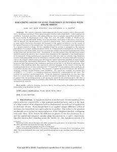
FIG. 1: Schematic for Josephson junctions with multiple tunneling channels. (a) A heterotic junction between single- and two-gap superconductors. (b) A grain-boundary junction between two-gap superconductors.
2
F=
2 X s′ s d x 2 (a ) + (axi )2 + VJ + (B y )2 , (1) 2 ′ 2 8πλ 8πλ 8π i i=1
�s-w ave (J 1
0.5
0.5
(1)
1
sin �
sin �
(1)
s-w ave ( J in > 0)
0 -0 .5
in
< 0)
0 -0 .5 -1 1
0.5
0.5
(2)
1
sin �
sin �
(2)
-1
0 -0 .5 -1
0 -0 .5 -1
-1
-0 .5
0
0.5
x= � J1
(a)
1
-1
-0 .5
0
0.5
1
x= � J1
(b)
0.0 3
dL x B y = � 0
berg et al. 16 in a context irrelevant to iron-pnictide superconductors. After the discovery of iron-pnictide superconductors, the importance of examining the effects of such a sign change grows significantly. A large amount of studies about Josephson junctions or tunneling spectroscopy have been reported, e.g., the Andreev bound states 17–20 , the dc-Josephson effect 22 , and the Riedel anomaly 23 . On the other hand, a theoretical research about the magnetic properties of Josephson junctions with multiple tunneling channels has been never so far studied, except for our previous work 24 . Thus, we develop theory of Josephson vortex in such a system on the basis of a microscopic approach for Josephson junctions 24,34 . First, we examine the heterotic SIS junction 24 . The situation is shown in Fig. 1(a), where the electrode 2 (1) is a two-(single-)gap superconductor with width s (s′ ), and the superconducting phases are expressed as ϕ(1) and ϕ(2) (ϕs ). The free energy density on the zx plane 24,34 is given by
s-wave
he t e r o t i ju n t io n 0.0 2
�s-wave
0.0 1 0 -0 .2
-0 .1
0
0.1
0.2
x=� J1
(c)
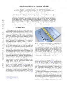
FIG. 2: (Color online) The single-vortex solution for the heterotic junction. We set Lx = 2.5λJ1 , η ′ = 103 , η1 = 103 , η2 = 1.56 × 10³ , j2 /j1 = 0.8, and |Jin |/j1 = 5.0. (a) s-wave (Jin > 0). (b) ±s-wave (Jin < 0). (c) The magnetic field penetrating into the junction. The solid line is for ±s-wave, while the dash one is for s-wave.
where VJ = −
2 X ~ji i=1
e∗
cos θ(i) −
θ(i) = ϕ(i) − ϕs − χ = ϕ(1) − ϕ(2)
~Jin cos χ, e∗
e∗ d z A , ~c = θ(1) − θ(2) .
(2) (3)
(5)
where η ′ = λ′ 2 /s′ d, ηi = λ2i /sd, and η¯−1 = η1−1 + η2−1 . Equation (5) is called modified Josephson relation 34 . Combined Eq.(5) with the Euler-Lagrange equations
1 + η ′ + η1 1 + η′ (1) sin θ + sin θ(2) λ2J1 λ2J2 η1 +sgn(Jin ) 2 sin(θ(1) − θ(2) ), λin 1 + η ′ + η2 1 + η′ sin θ(1) + sin θ(2) = 2 λJ1 λ2J2 η2 −sgn(Jin ) 2 sin(θ(1) − θ(2) ), λin
∂x2 θ(1) =
(4)
The label i represents the band index (i = 1, 2). We define ax and axi as, respectively, ax = (~c/e∗ )∂x ϕs −Ax1 and axi = (~c/e∗ )∂x ϕ(i) − Ax2 , where e∗ = 2e. The penetration depth of the superconducting state in the electrode 2 (1) is written as λi (λ′ ). The third term in Eq. (1) describes the Josephson coupling energy. As shown in Eq. (2), the first term represents the contribution from two different tunneling channels, j1 and j2 , and the last one is the internal Josephson coupling microscopically originating from an inter-band interaction 24,35 . The sign of Jin determines the relative phase difference, χ between the two order parameters in the two-gap superconducting electrode 2. When Jin < 0, the preferable value of χ becomes π, which corresponds to ±s-wave. The final term in Eq. (1) is the magnetic field energy, in which B y = d−1 (Ax2 − Ax1 ) − ∂x Az . Using Eq. (3) and the Euler-Lagrange equations with respect to Axℓ , we have 2 X η¯ e∗ d y ∂x θ(i) = (1 + η ′ + η¯) B , η ~c i=1 i
with respect to Az , ϕ(i) , and ϕs , we have the coupled sine-Gordon equations as
∂x2 θ(2)
(6)
(7)
−2 ∗ 2 ∗ 2 where λ−2 Ji = 4πde ji /~c and λin = 4πde |Jin |/~c . The coefficients of the coupling terms have opposite signs. Then, we call the equations “± coupled sine-Gordon equations.” We note that ± is not relevant to ±s-wave but common for Josephson junctions having multiple tunneling channels. Figure 2 displays a single Josephson vortex solution numerically obtained from Eqs. (6) and (7). The spatial scale is normalized by λJ1 , and the total length in the direction of x-axis is Lx = 2.5λJ1 . The boundary condition is given by θ(1) (−Lx /2) = 0, θ(1) (Lx /2) = 2π, θ(2) (−Lx /2) = χ0 , and θ(2) (−Lx /2) = χ0 + 2π. The internal phase difference χ is automatically chosen so that the free energy becomes minimum. We initially choose −π (0) for χ0 when Jin < 0 (> 0), and solve Eqs. (6) and (7) iteratively. For the junction parameters, we set η ′ = 103 , η1 = 103 , η2 = 1.56 × 10³ , j2 /j1 = 0.8, and |Jin |/j1 = 5.0. The width of the current core of the Josephson vortex for ±s-wave as shown in Fig. 2(b) is much wider than that in Fig. 2(a) for s-wave without
3 the sign change. Moreover, one finds an antisymmetric current pattern for ±s-wave 24 . We can find that χ is slightly modulated around the vortex center, although it is almost fixed to be a specific constant (0 or π). Using Eq. (5), we evaluate the magnetic field distribution around the Josephson vortex, as is shown in Fig. 2(c). We find a significantly enlarged distribution for ±s-wave compared to s-wave without the sign change. For further understanding of the above enlargement results, we turn back to Eqs. (6) and (7). When χ is rigidly fixed as 0 or π, we have the following equation, which are asymptotically valid except for the Josephson vortex core (i.e., |x| → ∞): ∂x2 θ(1) ∼ η˜1 (χ) sin θ(1) ,
∂x2 θ(2) ∼ η˜2 (χ) sin θ(2) ,
(8)
where η˜1 (χ) = (1 + η ′ + η1 )/λ2J1 + cos χ (1 + η ′ )/λ2J2 and η˜2 (χ) = (1 + η ′ )/λ2J1 + cos χ (1 + η ′ + η2 )/λ2J2 (χ = 0, π). Here, we emphasize that the characteristic spatial scale in Eq. (8) strongly depends on the type of pairing symmetry. Since η˜i (π) < η˜i (0), we claim that the solutions for ±swave are more widely spread than that for s-wave without the sign change. This asymptotic analysis well explains Figs. 2(a) and 2(b). In addition, using Eq. (5), the magnetic field distribution inside the junction is asymptotically obtained as p 2 X 2 η˜i (χ) η¯ Lx d y p B ∼A Φ0 η ˜i (χ)x] i=1 i cosh[ η
(9)
where A = (1+η ′ +¯ η )−1 Lx /2π. Thus, we clearly find that ±s-wave leads to an enlargement of the magnetic field distribution due to η˜i (π) < η˜i (0). The origin of such an enlargement is the cancellation between multiple tunneling channels as shown in Fig. 2(b). In addition, we point out that the relative phase difference between the superconducting gaps slightly fluctuates around a fixed value when |Jin | ≫ j1 , j2 24 . The asymptotic forms are valid in this case. The above qualitative discussion, Eqs. (8) and (9) does not depend on precise values of the junction parameters, as long as the condition is satisfied. On the other hand, a quantitative evaluation of the magnetic field distribution requires the detailed information of the junction parameters. We will discuss the quantitative way to identify the symmetry, i.e., s-wave or ±s-wave at the end of this paper. Second, we examine the grain-boundary junction as schematically shown in Fig. 1(b). Both the electrodes are assumed to be identical (two-gap) superconductors. This type of junction is observed in a weak-link between grains of a polycrystalline iron-based superconductor 5,6,26 . Alternatively, the situation is theoretically equivalent to the intrinsic junctions stacked along the c-axis. The free energy density is basically similar to Eq. (1), but there are two differences. The first term in P2 Eq. (1) is substituted with − i=1 (s/8πλ2i )(axi,1 )2 , where (i)
axi,1 = (~c/e∗ )∂x ϕ1 − Ax1 . The Josephson coupling en-
ergy term is replaced by VJ = −
2 X ~ji i=1
e∗
(i)
cos θ2,1 −
~j12 (2) cos(θ2,1 − χ1 ) e∗ 2
−
X ~Jin ~j21 (1) cos(θ2,1 + χ1 ) − cos χℓ , (10) ∗ e e∗ ℓ=1
(i)
(i)
(i)
(1)
where θ2,1 = ϕ2 − ϕ1 − (e∗ d/~c)Az2,1 and χℓ = ϕℓ − (2)
ϕℓ . The first (second) term in Eq. (10) is the intra(inter-)band Josephson coupling energy between the two electrodes 26,30 . The inter-band Josephson coupling originate microscopically from incoherent (momentum nonconserved) tunneling, which is the dominant process at rough boundaries. Repeating the same treatment as the previous case, we have the modified Josephson relation, 2 X e∗ d y η¯ (i) ∂x θ2,1 = (1 + 2¯ η) B η ~c 2,1 i=1 i
(11)
and the ± coupled sine-Gordon equations, (1)
1 + 2η1 1 (1) (2) sin θ2,1 + 2 sin θ2,1 + f1inter 2 λJ1 λJ2 η1 +sgn(Jin ) 2 (sin χ2 − sin χ1 ), (12) λin 1 + 2η2 1 (1) (2) sin θ2,1 + f2inter = 2 sin θ2,1 + λJ1 λ2J2 η2 −sgn(Jin ) 2 (sin χ2 − sin χ1 ), (13) λin η1 η2 (1) (2) = − 2 sin θ2,1 + 2 sin θ2,1 λJ1 λJ2 η2 η1 (2) (1) − 2 sin(θ2,1 − χ1 ) + 2 sin(θ2,1 + χ1 ) λJ12 λJ21 η1 + η2 +sgn(Jin ) sin χ1 , (14) λ2in
∂x2 θ2,1 =
(2)
∂x2 θ2,1
∂x2 χ1
where fiinter =
1 + ηi 1 + ηi (2) (1) sin(θ2,1 −χ1 )+ 2 sin(θ2,1 +χ1 ). (15) λ2J12 λJ21
Another relative phase difference χ2 is determined by the identity (1)
(2)
θ2,1 − θ2,1 = χ2 − χ1 .
(16)
Equation (14) can be regarded as the sine-Gordon equation with respect to an interband phase difference 35 . Assuming the physical situation in which superconductivity fully grows in each superconducting electrode and χ1 and χ2 are fixed as the same specific value inside the (i) (i) grain, we choose θ2,1 (−Lx /2) = 0, θ2,1 (Lx /2) = 2π, and χ1 (−Lx /2) = χ1 (Lx /2) = χ0 as the boundary condition for the single Josephson vortex. We choose π (0) as χ0 when Jin < 0 (> 0). From Eq. (16), we
4
0.5
(1)
0.5
sin � 2;1
0
-0 .5
1
1
0.5
0.5
(2)
-1
0
-0 .5
-0 .5
0
0.5
x= � J1
-1
-0 .5
0
0.5
1
y
dL x B 2;1 = � 0
0.0 2
�s-wave
0 -0 .2
-0 .1
0
0.1
0.2
x=� J1
(c)
FIG. 3: (Color online) The single-vortex solution for the Josephson junction between two-gap superconductors. The junction parameters are the same as in Fig. 2, except for j12 /j1 = j21 /j1 = 0.6. (a) s-wave (Jin > 0). (b) ±s-wave (Jin < 0). (c) The magnetic field penetrating into the junction. The solid line is for ±s-wave, while the dash one is for s-wave.
have χ2 (−Lx /2) = χ2 (Lx /2) = χ0 . Figure 3 displays the single Josephson vortex solution. The ratios, j1 , j12 /j1 = j21 /j1 = 0.6, and the values of the other junction parameters are the same as the previous. Figures 3(a) and 3(b) shows the shape of the single vortex solution for s-wave without the sign change and ±s-wave, respectively. The ±s-wave superconductivity leads to χi = π. Thus, Eq. (16) means that no phase difference (1) (2) between θ2,1 and θ2,1 appears even though the electrodes are ±s-wave superconductors. We find that no antisymmetric current pattern for ±s-wave appears. Figure 3(c) shows the spatial distribution of the magnetic field, which is evaluated via Eq. (11). We find the enlarging behavior for ±s-wave similar to the hetrotic SIS case. We also find the cancellation between the intra-band and the inter-band Josephson currents when Jin < 0 (i.e., χ1 = χ2 = π), from Eq. (10). Thus, the magnetic field distribution of the Josephson vortex enlarges in the ±swave symmetry. Finally, we discuss how to detect the enlargement of the Josephson vortex size experimentally. Hereafter, we focus on the heterotic junction system. A similar discussion is possible for the grain-boundary junction. First, we determine a characteristic spatial length for s-wave without the sign change in the case of j1 ≃ j2 . The Ambegaokar-Baratoff relation then gives a simple formula, Rn
= 3= 2
= 9= 1
s-w av e -0 .1
0
x=� 0
e1 + ∆ e2 ~Jc0 π~ ∆ ≃ . e∗ 4e2 2
0. 0 1 5 0. 0 1 0. 0 0 5
-0 . 2
s-wave
2-g a p SC s
= 1= 1
= 2= 3
= 1= 9
0.1
� � � � �
0.2
r r r s, r s, r s, r s,
=1 =3 =9 3= 2 9= 1 1= 1
= 1
s,
= 2
s,
= 1 = = =
0
x= � J1
(b)
ju n t io n b e tw e e n
0.0 1 0.0 0 5
0. 0 2
(b) 0.0 4
= 1
(a)
0
1
r
-0 .2
-1 -1
r r r r r
0.0 2 0.0 1 5
0
-0 .5
-1
(a)
< 0)
0
-1
sin � 2;1
sin � 2;1
(2)
-0 .5
in
dL x B y = � 0
(1)
sin � 2;1
1
dL x B y = � 0
�s-w ave (J
s-w ave ( J in > 0) 1
(17)
The quantity Jc0 is the critical current density in the het-
-0 . 1
0
0.1
0.2
x=� 0
FIG. 4: (Color online) The magnetic field penetrating into the heterotic junction, varying r = rn,1 /rn,2 . The spatial scale is λ0c , which is evaluated via Eq. (17). We set Lx = 2.5λ0c , e 2 /∆ e 1 = 0.82. η1 = 103 , η2 = 2.0 × 10³ , |Jin |/Jc0 = 10, and ∆ (a) The approximate formula, Eq. (9) for s-wave. The inset shows the comparison to the numerical solutions for s-wave (circle) when r = 1. (b) The comparison of the numerical solutions for ±s-wave to a s-wave vortex core size.
erotic junction for the the s-wave symmetry without sign change. The resistance of the junction in the normal state associated with the tunneling channel ji is written −1 −1 as rn,i . We note that Rn−1 = rn,1 + rn,2 and j2 /j1 = 1 i i 2 e e e e rn,1 ∆ /rn,2 ∆ . We define ∆ as ∆ = 2∆iS K(ki )/π, where ∆iS = min{∆s , ∆i }, ∆iL = max{∆s , ∆i }, ki = [1 − (∆iS /∆iL )2 ]1/2 , and K(ki ) is the complete elliptic integral of the first kind 36 . The superconducting gap amplitude in the electrode 1 (2) is written as ∆s (∆i ) as shown in Fig. 1(a). Here, an important point is that e i depends on only the superconducting the quantity ∆ gap amplitudes. The direct evaluation of each resistance, rn,1 or rn,2 , is not practical, but the combined one Rn is measurable in the normal state. Thus, one can evaluate e i , both of which are supposed to be Jc0 from Rn and ∆ experimentally measured, and define a spatial scale as p λ0c = ~c2 /4πde∗ Jc0 . Normalizing Eqs. (6) and (7) via λ0c , we can find that the equations have a free parameter r = rn,1 /rn,2 . Next, we estimate the magnetic field distribution by employing Eq. (9). We also check the dependence of r on the magnetic field distribution. Figure 4(a) shows distributions of the magnetic field obtained from Eq. (9) in various r for the s-wave without the sign change. We then find that r dependence of the distribution is not at all significant. Hence, one can adopt the result for r = 1 as a theoretical prediction for no sign change. Figure 4(b) presents a comparison with the ±s-wave case. We find that the field distributions in the ±s-wave case are much wider than that in the case without sign change except for the cases, e.g., r = 1/9 or r = 9/1. When r = 1/9, j2 /j1 ≃ 0.09, indicating that one of the multiple tunneling channels is inactive and the system is approximately described by a single-channel junction. This is not the case of the present iron-based superconductors. We emphasize that the magnetic field distribution of the Josephson vortex for the ±s-wave su-
5 perconductivity never obeys the prediction on the basis of the s-wave without the sign change except for such extreme cases. In other words, the observed length of the magnetic field extent is much larger than the theoretical size for the s-wave symmetry. In conclusion, we studied the single Josephson vortex solutions in the heterotic SIS Josephson and the grainboundary junctions, and revealed an anomalous enlargement of the vortex core size for ±s-wave compared to the size estimated by the Ambegaokar-Baratoff relation for no sign change. All phenomena were explained on the basis of the cancellation between different tunneling channels due to the ±s-wave superconductivity. As for the heterotic SIS Josephson junction, the cancellation appears between the two Josephson currents j1 and j2 .
1
2
3
4
5
6
7
8
9
10
11
12 13
14
15
16
17
Y. Kamihara, T. Watanabe, M. Hirano, and H. Hosono, J. Am. Chem. Soc. 130, 3296 (2008). M. Rotter, M. Tegel, and D. Johrendt, Phys. Rev. Lett. 101, 107006 (2008). R. Zhi-An, L. Wei, Y. Jie, Yi. Wei, S. Xiao-Li, L. ZhengCai, C. Guang-Can, D. Xiao-Li, S. Li-Ling, Z. Fang, and Z. Zhong-Xian, Chin. Phys. Lett. 25, 2215 (2008). H. Ogino, Y. Matsumura, Y. Katsura, K. Ushiyama, S. Horii, K. Kishio, and J. Shimoyama, Supercond. Sci. Technol. 22, 075008 (2009). T. Tamegai, Y. Nakajima, Y. Tsuchiya, A. Iyo, K. Miyazawa, P. M. Shirage, H. Kito, and H. Eisaki, J. Phys. Soc. Jpn. 77 Supplement C, 54 (2008); Physica C 469, 915 (2009). E. S. Otabe, M. Kiuchi, S. Kawai, Y. Morita, J. Ge, B. Ni, Z. Gao, L. Wang, Y. Qi, X. Zhang, and Y. Ma, Physica C 469, 1940 (2009). H. Ding, P. Richard, K. Nakayama, K. Sugawara, T. Arakane, Y. Sekiba, A. Takayama, S. Souma, T. Sato, T. Takahashi, Z. Wang, X. Dai, Z. Fang, G. F. Chen, J. L. Luo, and N. L. Wang, EPL 83, 47001 (2008). A. Kawabata, S. C. Lee, T. Moyoshi, Y. Kobayashi, and M. Sato, J. Phys. Soc. Jpn. 77, 103704 (2008). K. Hashimoto, T. Shibauchi, T. Kato, K. Ikada, R. Okazaki, H. Shishido, M. Ishikado, H. Kito, A. Iyo, H. Eisaki, S. Shamoto, and Y. Matsuda, Phys. Rev. Lett. 102, 017002 (2009). I. I. Mazin, D. J. Singh, M. D. Johannes, and M. H. Du, Phys. Rev. Lett. 101, 057003 (2008). K. Kuroki, S. Onari, R. Arita, H. Usui, Y. Tanaka, H. Kontani, and H. Aoki, Phys. Rev. Lett. 101, 087004 (2008); 102, 109902(E) (2009). Y. Bang and H.-Y. Choi, Phys. Rev. B 78, 134523 (2008). Y. Nagai, N. Hayashi, N. Nakai, H. Nakamura, M. Okumura, and M. Machida, New. J. Phys. 10, 103026 (2008). K. Kuroki, H. Usui, S. Onari, R. Arita, and H. Aoki, Phys. Rev. B 79, 224511 (2009). N. Nakai, H. Nakamura, Y. Ota, Y. Nagai, N. Hayashi, and M. Machida, arXiv:0909.1195. D. F. Agterberg, E. Demler, and B. Janko, Phys. Rev. B 66, 214507 (2002). S. Onari and Y. Tanaka, Phys. Rev. B 79, 174526 (2009).
On the other hand, the cancellation between the intraand inter-grain Josephson currents occurs in the case of the grain-boundary junction. Such a cancellation leads to an effective change in a characteristic spatial length (e.g., penetration depth). Consequently, the Josephson vortex widely provides a reliable way to detect the gap symmetry in iron-based superconductors. The authors (Y.O. and M.M) wish to acknowledge valuable discussion with S. Shamoto, N. Hayashi, Y. Nagai, H. Nakamura, M. Okumura, N. Nakai, and R. Igarashi. The work was partially supported by Grantin-Aid for Scientific Research on Priority Area “Physics of new quantum phases in superclean materials” (Grant No. 20029019) from the Ministry of Education, Culture, Sports, Science and Technology of Japan.
18
19 20
21
22
23 24
25
26
27
28
29
30
31
32
33
34
35
36
J. Linder and A. Sudbø, Phys. Rev. B 79, 020501(R) (2009). Y. Nagai and N. Hayashi, Phys. Rev. B 79, 224508 (2009). A. A. Golubov, A. Brinkman, Y. Tanaka, I. I. Mazin, and O. V. Dolgov, Phys. Rev. Lett. 103, 077003 (2009). D. Parker and I. I. Mazin, Phys. Rev. Lett. 102, 227007 (2009). J. Linder, I. B. Sperstad, and A. Sudbø, Phys. Rev. B 80. 020503(R) (2009). D. Inotani and Y. Ohashi, Phys. Rev. B 79, 224527 (2009). Y. Ota, M. Machida, T. Koyama, and H. Matsumoto, Phys. Rev. Lett. 102, 237003 (2009). C.-T. Chen, C. C. Tsuei, M. B. Ketchen, Z.-A. Ren, and Z. X. Zhao, arXiv:0905.3571. Y. Ota, M. Machida, and T. Koyama, J. Phys. Soc. Jpn. 78, 103701 (2009). C. C. Tsuei and J. R. Kirtley, Rev. Mod. Phys. 72, 969 (2000). C. C. Tsuei, J. R. Kirtley, C. C. Chi, Lock See Yu-Jahnes, A. Gupta, T. Shaw, J. Z. Sun, and M. B. Ketchen, Phys. Rev. Lett. 73, 593 (1994). J. R. Kirtley, M. B. Ketchen, K. G. Stawiasz, J. Z. Sun, W. J. Gallagher, S. H. Blanton, and S. J. Wind, Appl. Phys. Lett. 66, 1138 (1995). A. Brinkman, A. A. Golubov, H. Rogalla, O. V. Dolgov, J. Kortus, Y. Kong, O. Jepsen, and O. K. Andersen, Phys. Rev. B 65, 180517(R) (2002). V. Ambegaokar and A. Baratoff, Phys. Rev. Lett. 10, 486 (1963); 11, 104 (1963). A. Brinkman, A. A. Golubov, and M. Yu. Kupriyanov, Phys. Rev. B 69, 214407 (2004). A. Anishchanka, A. F. Volkov, and K. B. Efetov, Phys. Rev. B 76, 104504 (2007). M. Machida, T. Koyama, A. Tanaka, and M. Tachiki, Physica C 331 85 (2000). A. Gurevich and V. M. Vinokur, Phys. Rev. Lett. 90, 047004 (2003). E. T. Whittaker and G. N. Watson, A Cource of Modern Analysis 4th ed. (Cambridge University Press, Cambridge, England, 1927), Chap.22.