The 10 th Workshop on RF Superconductivity, 2001, Tsukuba, Japan
STATUS OF MULTIPACTING SIMULATION CAPABILITIES FOR SCRF APPLICATIONS F.L.Krawczyk+, Los Alamos National Laboratory, Los Alamos, NM, USA Abstract In recent years the understanding of potential multipacting effects in RF structures has become increasingly important. This demand is predominantly triggered by two trends in superconducting accelerator applications. One is the need for transferring higher levels of RF power into resonators that require special considerations in designing power couplers. The second is the increasing use of superconducting cavities for ion and proton acceleration. For those a number of different structures need to be designed that reflect the change in particle velocity along the accelerator. For these applications structure verification by prototyping is not cost effective anymore. It should be noted that the same is true for room temperature structures, whose design in the future will also benefit from the recent developments in this field. Furthermore, while rotationally or translationally symmetric structures can often be approached (semi)-analytically, new generation cavities like spoke resonators need a full 3D treatment. This presentation will give an overview of recent developments of more accurate modeling tools.
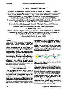
1 INTRODUCTION Multipacting is an undesired, resonant build-up of electrons inside RF-structures operated under vacuum. Electrons can be released from a RF surface due to the surface electromagnetic field or other processes. If they return to the surface close to their origin in an integer number of RF-periods, with energies where the secondary emission yield of the RF-surface material is larger than unity, an electron cascade will build up that disrupts the operation of the structure (Figure 1.) This disruption can be in the form of damage to the surface and/or due to absorption of an increasingly significant amount of RF power that becomes unavailable for its original purpose.
Figure 1: A visualization of 1st to 3rd order one-point multipacting, taken from [1]. The order of a multipacting resonance is a measure of the number of
full RF-cycles it takes an electron to return to its original emission site. The classification as n-point multipacting tells the number of impact sites (n) between whom the particle resonates. While one-point multipacting is the most frequently encountered, twopoint multipacting (oscillation between two impact sites) also plays an important role, e.g. in elliptical cavities [2]. While multipacting always was a phenomenon to be considered for RF-structures, recently it became increasingly important due to some changing trends in the development of superconducting accelerators and the related structures. High current linacs require larger amounts of power guided through couplers into the resonators. While for moderate power levels multipacting could be avoided by increasing the coupler dimensions, space considerations for the higher levels do not allow this approach anymore. Also the related higher gradients in the resonators mean that a larger range of field levels is seen inside the cavity and thus the probability of crossing a multipacting level is growing. Last, but not least, the increasing use of new, reduced-β structures makes it more difficult to judge their behavior through simple means or from previous knowledge from similar structures. Their evaluation often even requires taking into account fully three-dimensional effects.
2 TECHNIQUES TO DEAL WITH MULTIPACTING There are a number of approaches to deal with multipacting. The best approach is to avoid it altogether. This can be done by changing the shape of the RFstructure or by changing the surface properties of the structure. If operation is required at a field level that is above a multipacting resonance inherent to the structure, problems can be avoided by changing the electromagnetic field distribution to disrupt the resonance pattern of the electrons. Also conditioning through the resonance to operate at a level above the resonance is possible for “soft” multipacting barriers. A “soft” barrier is a barrier that can be passed. The conditioning is thought to occur via multipacting impacts, which clean the surface and reduce the secondary emission yield below unity. Operation at a resonance needs to be avoided in any case.
2.1 Changing the Geometry The best approach to avoid multipacting problems is to modify the geometry of a structure to totally avoid
_________________
[email protected]
+
108
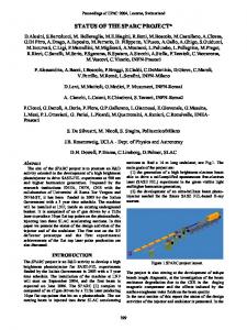
The 10 th Workshop on RF Superconductivity, 2001, Tsukuba, Japan multipacting resonances for the range of the structure’s operation. For coaxial lines this could mean changing the diameter or the impedance of the line [3]. For resonators this could mean changing the shape of the RF-surface in the problematic region. Figure 2 shows the concept of a major change in RF-resonator geometry that became standard for most superconducting cavities in operation today. It originated from multipacting problems encountered in the HEPL accelerator [4] at Stanford University.
Figure 2: The classic example for a successful geometry change is the HEPL cavity. Singlepoint multipacting on the flat outside wall led to the preferred use of elliptical cavities for superconducting applications. Figure taken from [5].
called biasing, uses DC electric voltages in the kV-range for coaxial couplers (see e.g. [9]). Recently, for waveguide couplers, DC magnetic fields have been proposed for biasing [10]. Biasing can also be a useful feature during RF-conditioning of couplers, even if the biasing voltage is not needed during the coupler operation [11].
2.4 Finding the Remedy The evolving approaches to multipacting problems reflect the development of computational tools in the last few decades. At first, the experimental approach (you see a problem and you fix it), dominated. Tools to preempt multipacting problems developed quickly. Initially, analytic formulations or empirical laws for resonance conditions prevailed: due to the complex interaction between RF-fields, tracking of many particles, and the need for accurate surface property models, a full numerical treatment was not feasible for a long time. With more computing power, first 2D, then also full 3D simulation tools were developed to investigate the potential for multipacting in new RF-structures.
3 OVERVIEW OF ANALYTIC OR EMPIRICAL MODELS
2.2 Changing Surface Conditions Even when resonant conditions for electrons exist, they do not automatically lead to a resonant buildup of electrons. If the secondary emission coefficient of the surface at the impact energy of the electron is less than unity, no electron might be re-emitted or this single electron might just be scattered off the surface. This effect opens the possibility to choose materials with a smaller secondary emission coefficient to minimize or avoid electron multiplication without having to change the geometry. If no other material is suitable, there are a few more options to improve the performance of the RFstructure. A standard technique for power couplers is Ti or TiN coating [6]. Usually it is the ceramic window that is coated. The secondary emission coefficient of Ti or TiN over a wide range of impact energies is less than unity, thus not leading to electron multiplication. Metallic surfaces often cannot be coated. For these, conditioning with modulated RF-power can clean surfaces and lower secondary emission. Recent work at CERN [7] and KEK [8] show that choosing different chemicals for cleaning RF-surfaces could reduce secondary emission significantly.
2.3 DC Biasing Since resonance conditions for electrons are tightly connected to the shape of RF-surfaces and the resulting RF-fields, a minor change in the RF-fields could already provide a disruption of the resonance paths. A standard procedure for power couplers uses the superposition of DC-fields over the resonant RF-fields to obtain a disruption of the resonance conditions. This technique,
109
3.1 Scaling Laws and Hatch Diagrams Analytic expressions for resonance conditions lead to the "Hatch-diagrams" [12] for RF-gaps. For simple geometries scaling laws were formulated, that allowed to know the power levels for resonances, without doing any elaborate evaluation of a structure. Equation (1) and (2) give such a law for straight coaxial lines [13,14]: PMP α (f*d) 4 Z1
(1)
PMP α (f*d) 4 Z2
(2)
Equation (1) gives the scaling of multipacting levels for one-point multipacting, as they vary with frequency (f), gap-size (d) and coaxial line impedance (Z). Equation (2) gives the same law for the two-point resonances. Other examples are the “poor man rules” as established by R. Parodi et al. For potential one-point multipacting in RF-cavities the relation between frequency and magnetic field for each order is approximately [15]: (3) f/N = e B0 / 2πm. For potential two-point multipacting this relation is [16]: (4) 2f/(2N-1) = e B0 / 2πm, where N is the order of the multipacting phenomenon, e and m are the charge and mass of the electron and B0 is the local magnetic field at the surface. Applying these rules requires the knowledge of the location, where multipacting takes place.
The 10 th Workshop on RF Superconductivity, 2001, Tsukuba, Japan
3.2 Empirical Laws without the Need for Particle Simulations Semi-analytic approaches were and still are important. In general, local RF surface fields predominantly determine electron trajectories. This fact has been used to derive formulas that for similar types of surface geometries (e.g. β≈1.0 elliptical cavities) give dangerous field levels for a specific frequency. Examples are J. Tueckmantel's [17] work from 1989 and K. Saito's [2] work presented in this workshop.
4 GENERAL STRATEGIES FOR A NUMERICAL APPROACH In recent years, numerical tools have become increasingly important for the evaluation of rf-structures. They can be applied to a wide range of 2D and 3D structures. While there are significant differences among the existing tools, the general approach for all that are in use right now can be mapped to the same three steps. These steps are performed in every case, with variations in execution, strategies for detailed implementation and numerical methods. The first step is the definition of the geometry and the calculation of the RF-fields in this geometry. In a second step, surface properties are imposed onto the RF-surfaces and a large number of particles are introduced into the structure. After particle trajectories for a number of initial conditions are calculated, in the third step identification of resonant behavior in general and multipacting behavior is done. The details are elaborated on in the following sub-sections.
4.1 First Step: Geometry Description and Electromagnetic Fields All multipacting simulation packages start out with a geometry description and the calculation of the RF fields that move the electrons. Some packages use their own electromagnetic field modeler. But most packages use existing solvers like MAFIA [18] or Superfish [19] and transfer the field solutions into their particle tracking software. For the choice of field modeler the crucial point is the quality of the RF-fields at the RF-surfaces. While some codes (especially the ones written for the purpose of multipacting simulations) have smooth surface fields that are required for a proper description of physics during electron emission, other codes require a correction of the surface fields, e.g. by interpolation, to have a good description of the fields during particle emission. All codes described here either use a code with good surface fields or correct the fields to make them suitable for the task.
4.2 Second Step: Introduction of Particles, Surface Properties In the second step the properly prepared model of surfaces and fields is extended. Material properties relevant to electron emission, re-emission and and/or
110
scattering are associated to the RF-surfaces and particles with a wide range of initial conditions (position, kinetic energy, and/or emission angle) are introduced into the calculation volume. All these particles are then tracked over a number of RF-periods. For this tracking, besides the particle conditions, RF-phase and field levels are also varied over the range of interest. Particle histories, including impact times/phases, impact energies, impact locations and re-emission are recorded. Typically several 106 combinations of initial conditions are calculated. To simulate the multipacting correctly, an accurate model of the surface properties is required. Standard SEY (Secondary Emission Yield) tables might reflect the ideal properties of the RF-surface. The actual properties will depend on the cleanliness and chemical treatment of a surface. Some programs evade this problem by assuming during the tracking that all particles can be re-emitted. This gives all possible resonances, even though some might not be sustained due to the SEY coefficient being less than 1.0.
4.3 Third Step: Evaluation of Particle Data to Identify Multipacting In a third and final step semi-analytic and statistical methods are used to identify resonant behavior in the collection of particle tracking data. Some programs check if particle data fall into areas in phase space that fulfill resonance conditions. Most programs use the concept of counter and distance functions developed by a group at University of Helsinki. The functions are a statistical means to identify survival of particles and recurrence of initial conditions at re-emission. These functions are defined independent of the explicit SEY data. A modification, the enhanced counter functions, folds in the explicit material information during this last step. A more detailed description can be found below and in the thesis of P. Ylae-Oijala [20].
5 OVERVIEW OF ACTIVE DEVELOPMENTS AND SOFTWARE At the time of this review seven groups in the field had active programs or developments of programs that can be used to study potential multipacting effects in RFstructures. Three of the programs can be applied to 3D problems while the rest are applicable to 2D structures. Considering that most superconducting cavities are rotationally symmetric, these 2D programs do still cover a wide range of interesting problems. Some of the groups are working on the extension of their codes to 3D capabilities. All programs are individual implementations of the three steps described in the previous chapter. They have all been benchmarked by simulation of known multipacting behavior in either the HEPL [4] cavity or in a straight coaxial line. Table 1 gives an overview of some features of each of these seven programs. In addition, a more detailed description of its features is provided for each individual program. The amount of detail provided depends on the
The 10 th Workshop on RF Superconductivity, 2001, Tsukuba, Japan information made available by the authors or by their publications.
Table 1: Multipacting Simulation Software Code Name
EM Field Solver
Tracking Algorithm
Helsinki
MultiPac
Included
Runge-Kutta
Saclay
MUPAC
Superfish*
Runge-Kutta
Genoa
TRAJEC TTWTR AJ
OSCAR2D*
Standard Newton
Cornell I
MULTIP
Cornell II
XING
Albuquerque
TRAK3D
Included
Runge-Kutta
Moscow
MULTP
Superfish, MAFIA*
Adams-2D Leapfrog-3D
SUPERLAN S (Superfish*) MAFIA, analytic
Runge-Kutta Leapfrog Runge-Kutta
+
Emission Effects& SE, Ekin= user α=0, SE Ekin= user SE, scattering, Ekin= user SE, FE, Ekin= user α=0, SE Ekin= 2eV SE, FE, Ekin= user SE, Ekin= user
Geometry
Scanning Multipacting Decision+ Parameters$
2D
s, φ, α, Ea
CF/ECF/DF
2D
s, φ, Ea
ECF/DF
2D
s, φ, α, Ea
Spatial/time focusing
2D
s, φ, α, Ea
Time focusing
3D
s, φ, Ea
CF/ECF/DF
3D
s, φ, α, Ea
2D, 3D
s, φ, α, Ea
Spatial Focusing Phase Focusing
$ The scanning parameters are position (s), RF-phase (φ), emission angle (α) and field level (Ea). & The user can choose the kinetic energy Ekin at the initial electron emission in most programs. Secondary emission (SE) and field emission (FE) are the abbreviated effects.
Counter Functions (CF), Enhanced Counter Functions (ECF) and Distance Functions (DF) have been originally proposed and implemented by the Helsinki group. * The electromagnetic fields from these solvers are improved at the RF-surfaces for a more accurate treatment of multipacting problems.
5.1 MultiPac from Helsinki [21] The multipacting code from the University of Helsinki has been developed in the framework of the TESLA project to study axisymmetric RF-structures such as elliptical cavities and coaxial power couplers. The software is distributed freely for research. This package is one of only two with an incorporated electromagnetic field solver that is adapted to the specific needs of multipacting simulations [21]. The solver can treat axisymmetric RF resonators and coaxial lines with ceramic windows operated in traveling wave, standing wave, and mixed wave modes [22]. Particles can be started anywhere on the RF-surfaces with user-defined starting energies and emission angles. Trajectories are calculated with a Runge-Kutta-Fehlberg integration scheme. The particle movements are recorded for a user-defined range of RF-phases and field levels. Particle re-emission is determined from the RF-phase at the time of impact and the SEY value for the impact energy. To provide particle statistics in the end that allow identifying potential multipacting, a number of useful functions have been implemented. These functions will be described in sufficient detail here as they provide the basis for multipacting statistics in most of the simulation programs represented in this publication. Counter Functions (CF) record surviving primary particles. This function provided field levels at which resonant conditions are satisfied. Enhanced Counter Functions
111
(ECF) record all surviving secondary electrons. This function shows which of the resonant conditions have impact energies that create electron multiplication. The final piece of information that locates the occurrence of multipacting on the RF-surface is provided by the Distance Functions (DF); they provide the distance between the original particle emission site and the final impact site during the calculation interval. The minima of this function indicate the emission sites that can create multipacting. MultiPac is one of the first codes with an easy to use graphical (MATLAB based) interface for the general user. Geometry definition, parameter space and also visualization are all controlled by this interface. The software at present requires a personal computer running the Linux operating system.
5.2 MUPAC from Saclay [23] The multipacting code from CEA-Saclay has been developed for applications related to high current proton linacs for transmutation applications. Like MultiPac, the original applications have been elliptical cavities and coaxial power couplers. This 2D code uses a recent version of Superfish [19] for the calculation of the electromagnetic fields. Where necessary the surface fields are smoothed by a higher order interpolation. For the particle tracking the user can specify Secondary Emission Yield (SEY) curves. Particles are started in a raster everywhere on the contour of the RF-surface. The
The 10 th Workshop on RF Superconductivity, 2001, Tsukuba, Japan initial emission is normal to the surface. The user can modify the default value (2 eV) for the kinetic energy. All starting positions are scanned for a range of field levels and the full range of RF-phases. Re-emission is decided from the SEY curve, for re-emission also the impact angle is considered. To identify multipacting the “enhanced counter function (ECF)” and “distance function (DF)” concepts developed for the MultiPac code are used. The DF implementation includes periodic propagation of impact sites along RF-transmission lines to cover travelling wave operation in power couplers. The Saclay code development addresses the need for running a large number of particles in complicated structures. The tracking algorithm for this highly parallel problem (all particles can be tracked independently) is formulated to run on parallel multiprocessor systems that can consist of a network of UNIX machines. The standard version (no parallel processing support) of the program is written in C and is platform-independent.
5.3 TWTRAJ from Genoa [24,25] The Genoa multipacting simulation software has one of the longest histories in the field of studying multipacting phenomena. It originated from J. Halbritter in Karlsruhe in the mid-1970s and is now maintained and developed at INFN in Genoa. The electromagnetic field solver OSCAR2D [26] has also been developed by the INFN group. OSCAR2D includes a special formulation of its differential equations that result in a highly accurate solution at the RF-surface, an essential requirement for accurate multipacting simulations. Axisymmetric resonators and RF-guides with travelling and standing waves can be treated. The relativistic equations for tracking particles are solved with the standard Newton method. Particles are emitted at user-defined locations from the RF-surface. They start with a fixed, user-defined kinetic energy. All starting positions are scanned for a range of field levels and RF-phases. Particle emission is also scanned for a range of emission angles. The SEY is used in parametric form. The user can change the parameterization. Reemission takes into account SEY, elastic and inelastic scattering and Coulomb back scattering. The re-emission due to each of these effects is determined from the impact energy and probability distribution functions via Monte Carlo techniques. Particle impact sites and times are scanned for recurrence of impact regions (space focusing) and coincidence of impact times with multiples of half RFperiods (time focusing). An analysis of plotted trajectories is required for this process. Semi-statistical methods that count numbers of surviving electrons versus field levels support the analysis. The simulation package runs on personal computers under MS Windows and has a proven track record of successful applications for a variety of major accelerator projects.
112
5.4 MULTIP from Cornell I [27,28] This multipacting simulation program has been developed at Cornell University. Its original application has been for field emission (FE) studies in 2D rotationally symmetric structures, such as elliptical cavities. The multipacting simulation capability has been added on. Its electromagnetic fields are taken from SUPERLANS [29] or an older version of Superfish (Version 4) [19]. The Superfish 4 surface RF-fields were not sufficiently accurate. This is an artifact that has been removed in later versions of Superfish. SUPERLANS fields are suitable for multipacting simulations without any further processing of the surface fields. A Runge-Kutta scheme is used for particle tracking. Particles are started in a raster everywhere on the contour of the RF-surface. In addition, the user can decide on the initial kinetic energy and emission angle. No explicit SEY curve is incorporated into the code, except to stop reemission if the impact energy falls outside a user-defined range. This range is generally chosen to be wider than the worst-case range of impact energies with SEY > 1, to insure that resonant trajectories are not accidentally stopped. Particles are tracked over a user-defined range of field levels and RF-phases. Particle survival as a function of RF-phase and kinetic energy on impact is monitored. Potential multipacting behavior is identified by counting the number of surviving particles with impact energies inside the user-defined range for each field level. For particles that show resonant behavior, the impact conditions are recorded. It is up to the user to assess the risk of multipacting based on the impact energy, the impact angle, and the number of initial phases and positions that produce the resonant trajectory. It is in this final manual step that the user may consider a specific dependence of the SEY on impact energy and impact angle. This simulation program had a good verification by comparison of simulations with temperature maps on single-cell CEBAF cavities [30]. For the time being it is supported under DEC-VMS only.
5.5 Xing from Cornell II [10] Driven by the needs of the research done at Cornell, a second code for 3D multipacting simulations has been developed. This code uses the electromagnetic fields either provided by MAFIA [18] or derived from analytic models for simulations in rectangular waveguides. Waveguide modes in travelling wave, standing wave and mixed wave modes can be evaluated. Particle tracking also uses a leapfrog scheme. Particles are started in a raster everywhere on the contour of the RF-surface. The initial particle emission happens at constant kinetic energy (2 eV) normal to the RF-surface. A parametric SEY curve for “wet-prepared” niobium was originally used for the re-emission of particles. This has been extended to accept also other more realistic SEY data for various materials. Particles are tracked over a predefined range of field levels and RF-phases.
The 10 th Workshop on RF Superconductivity, 2001, Tsukuba, Japan The XING code also uses the CF, ECF and DF concepts developed for the MultiPac Code. First applications of this simulation program have been used to develop a slot concept and a DC magnetic bias to suppress multipacting in rectangular waveguides for CESR [31]. Experiments to verify these concepts will be done in the CESR accelerator at the end of 2001. This software is supported on DEC Alpha computers under UNIX.
providing a filter function that specifies a window of kinetic energies, where the SEY is larger than 1.0. In the second mode of operation, the potential multiplication can be investigated further by tracking the particles and generating trajectories and creating statistical data from particle counts. The software is freely available for MS Windows based personal computers. Both versions (2D and 3D) provide a window driven graphics user interface.
5.6 TRAK-3D from UNM Albuquerque [32]
6 OUTLOOK
The TRAK-3D particle-tracking program is part of a larger commercial electromagnetics package. Evaluation of multipacting phenomena is only one application of this code that predominantly is designed for RF gun design. The electromagnetic fields are calculated with another solver from the same package. The solutions at the RF surfaces do not require additional smoothing to obtain suitable fields for the study of multipacting phenomena. Particles can be introduced into the volume with arbitrary positions and momenta. They are tracked with a Runge-Kutta scheme. The user can specify arbitrary SEY curves that are used to decide stopping or re-emission of particles. Particle histories are stored in legible form for transfer into a spreadsheet or other external programs. Evaluation and detection of multipacting needs to be done by the user. No predefined statistics is implemented, yet. While this program is less specialized for multipacting simulations, its application to arbitrary 3D structures makes an interesting candidate for novel accelerator structures. The software is supported on a personal computer platform; the use of dynamic memory allocation makes it suitable for large problems or for a large number of particles.
5.7 MULTP from Moscow [33,34] The multipacting simulation program has a 2D implementation for axisymmetric structures and a 3D implementation for arbitrarily shaped structures. The RFfields can be taken from MAFIA (3D) [18] and Superfish (2D) [19]. The required field format for the particle tracking is published; thus replacing these electromagnetic solvers by others is the user’s choice. The 3D implementation using MAFIA includes a field interpolation procedure to smooth the fields at curved RFsurfaces. The user can introduce particles at any position in the geometry. Positioning can be done by coordinates, regions, or interactive mouse input. Trajectories are calculated for user-defined RF phase and field level ranges. Also particle momenta are user-controlled. The user also specifies the multipacting orders to look for. The program has two modes of operation. In the first mode, particle trajectories are evaluated to find parameter sets that generate resonant behavior. Phase-diagrams are generated that provide Ea vs. φ phase-space plots to visualize combinations of field and phase that do have the potential for multipacting. SEY effects are included by
113
In the last decade the capabilities of treating multipacting phenomena beyond simple models have increased significantly. Higher computing power allows addressing increasingly complex RF structures. The complexity can be a larger number of particles that can be tracked as well as the treatment of arbitrary 3D structures. Recently developed codes benefit from the existence of benchmarking problems, such as the CERN coaxial coupler and the HEPL cavity. As an example of the complexity that these simulators can reach, the Russian code MULTP as a first published application of the 3D simulator did a study of multipacting phenomena in the ANL spoke resonator [34]. Comparison with laboratory measurements can now be done to provide benchmarks also for 3D structures. The resulting overall higher accuracy of these simulation programs allows for better predictions of structure behavior for new structures, thus making design and operability of these structures faster and cheaper.
7 ACKNOWLEDGEMENT I wish to thank the following individuals for providing a lot of useful information on their projects and software: R. Parodi, G. Romanov, J. Tueckmantel, G. Devanz, S. Humphries, R. Geng and W. Hartung. My special thanks go to W. Hartung for carefully reading the final manuscript. I also wish to express thanks to K. Shepard, H. Padamsee, E. Zaplatin, and J. Halbritter for providing additional information or being available for helpful discussions.
8 REFERENCES [1]
H. Padamsee, J. Knobloch, T. Hays, “RF Superconductivity for Accelerators”, Wiley Series in Beam Physics and Accelerator Technology, New York 1998. [2] K. Saito, “Experimental Formula of the On-set Level of Two-point Multipacting Over the RF Frequency Range 500MHz to 1300 MHz”, Proceedings of this workshop. [3] E. Schmierer et al., “Design of the ADTF Spoke Cavity ED&D Input Coupler”, Proceedings of this workshop.
The 10 th Workshop on RF Superconductivity, 2001, Tsukuba, Japan [4] C.M. Lyneis, H.A. Schwettmann and J.P. Turner, “Elimination of Electron Multipacting in Superconducting Structures for Electron Accelerators”, Applied Physics Letters, Vol. 31, No.8, 15 October 1977. [5]http://w4.lns.cornell.edu/public/CESR/SRF/BasicSRF/ SRFBas1.html, “Superconducting RF, A Primer”, Based on the Ph.D. Dissertation of J. Graber, Cornell University, 1993. [6] J. Lorkiewicz, B. Dwersteg, A. Brinkmann, W. Moeller, D. Kostin and M. Layalan, “Surface TiN Coating of TESLA Couplers at DESY as an Antimultipacting Remedy”, Proceedings of this workshop. [7] V. Baglin, B. Henrist, N. Hilleret, E. Mercier, C. Scheuerlein, “Ingredients for the Understanding and the Simulation of Multipacting”, Proceedings of the Chamonix X Meeting, January 2000, http://cern.web.cern.ch/CERN/Divisions/SL/publicatio ns/chamx2k/contents.html. [8] R. Noer, S. Mitsunobu, Y. Kijima and K. Saito, “Secondary Electron Yield of Nb RF Cavity Surfaces”, Proceedings of this workshop. [9] H. Kindermann et al., “Status of RF Power Couplers for Superconducting Cavities at CERN”, Proceedings of EPAC 1996, Rome Italy. [10] R. L. Geng et al., “Exploring Multipacting Characteristics of a Rectangular Waveguide”, Proceedings of PAC99, New York, USA, 1999 [11] Y. Kijima, S. Mitsunobu, T. Furuya, “The Conditioning of the Input Coupler for KEKB Superconducting Cavity”, Proceedings of this workshop. [12] A.J. Hatch, “Suppression of Multipacting in Particle Accelerators”, NIM 41 (1966) 261. [13] J.P. Budlinger, A. Laisne, “Effet d’avalanche en geometrie plane et cylindrique”, NIM 61 (1968) 253. [14] P. Ylae-Oijala, D. Proch, “Analysis of Multipacting in Coaxial Lines”, E. Somersalo, PAC95, Dallas (1995). [15] P. Fernandes, R. Parodi, G. Bienvenu, “An Investigation on the Field Emitted Electrons in Travelling Wave Accelerating Structures”, NIM A, 320 (1992) 1-8. [16] P. Fabbricatore, G. Gemme, R. Musenich, R. Parodi, S. Pittaluga, “Experimental Evidence of MP Discharges in Spherical Cavities at 3 GHz”, Proceedings of the 7th Workshop on RF Superconductivity, Gif sur Yvette (1995). [17] J. Tückmantel, “One Point Multipacting Levels Determined Without Particle Tracking”, Proceedings of the 4th Workshop on RF Superconductivity, Tsukuba, Japan, 1989. [18] www.cst.de [19] laacg1.lanl.gov/services.html [20] P. Ylae-Oijala, “Multipacting Analysis and Electromagnetic Field Computation by the Boundary Integral Equation Method in RF Cavities and Waveguides”, Ph.D. Dissertation at the Rolf
114
Nevanlinna Institute, University of Helsinki, Finland, (1999) [21] P. Yla-Oijala, D. Proch, “MultiPac - Multipacting Simulation Package with 2D FEM Field Solver”, Proceedings of this workshop. [22] P. Ylae-Oijala, “Analysis of Electron Multipacting in Coaxial Lines with Traveling Wave and Mixed Waves”, TESLA-Report 97-20 [23] G. Devanz, “Multipactor Simulations in Superconducting Cavities and Power Couplers”, Phys. Rev. Special Topics – Accelerators and Beams, Vol 4, 012001 (2001) [24] R. Parodi, P. Fernandes, “TWTRAJ Users Guide”, LAL SERA 90-224, 20-December 1990 [25] R.Ballantini, A.Chincarini, G.Gemme, R.Parodi, A.Podesta, “TWTRAJ, a Computer Code for MP Simulation in Superconducting Cavities”, Proceedings of this workshop. [26] P.Fernandes and R.Parodi, IEE Trans. Magn., Vol 24, (1998), p 154 [27] R. Ferraro et al., “Guide to Multipacting/Field Emission Simulation Software, 6th Edition”, Cornell LNS Report SRF/D-961126/10, 1996 [28] W. Hartung, F. Krawczyk, H. Padamsee, “Studies of Multipacting in Axisymmetric Cavities for MediumVelocity Beams”, Proceedings of this workshop. [29] D.G.Myakishev, V.P.Yakovlev, “An Interactive Code SUPERLANS for Evaluation of RF-Cavities and Acceleration Structures”, Proceedings of PAC91, San Francisco, California, USA. [30] J. Knobloch, W. Hartung, H. Padamsee, “Multipacting in 1.5 GHz Superconducting Niobium Cavities of the CEBAF Shape”, Proceedings of the 8th workshop on RF Superconductivity, 1997, Abeno Terme, Italy. [31] R.L. Geng, H. Padamsee, V. Shemelin, “Multipacting in a Rectangular Waveguide”, Proceedings of PAC2001, Chicago, USA. [32] S. Humphries, jr., TRAK3D http://www.fieldp.com/maze/trak3d.html [33] L.V. Kravchuk et al., “The Computer Code for Investigation of the Multipactor Discharge in RF Cavities”, Proceedings of Pac99, New York, USA [34] L. V. Kravchuk et al., “Multipactoring Code for 3D Accelerating Structures”, Proceedings of Linac2000, Monterey, USA