uous structural data collection using a wireless network [4],. [5], [6]. .... of the structure and F is a vector specifying the external forces. y = [ y1. ··· yn. ] ..... discovery, identification and localization are hard research .... This permits faster recovery of.
Structural Damage Detection and Localization Using N ET SHM Krishna Chintalapudi∗ , Jeongyeup Paek∗ , Om Prakash∗ , Tat Fu† , Karthik Dantu∗ , John Caffrey† , Ramesh Govindan∗ and Erik Johnson† ∗ Computer
Science Department, University of Southern California, Los Angeles, CA 90089, USA † Civil Engineering Department, University of Southern California, Los Angeles, CA 90089, USA Abstract— Structural health monitoring (SHM) is an important application area for wireless sensor networks. Recent work has examined the design of wireless sensor networks for structural data acquisition systems. The eventual goal of structural monitoring, however, is autonomous detection and localization of structural damage. Developing practical damage detection and localization schemes is still an area of active research and there exists a large array of techniques. Structural engineers typically implement and test SHM algorithms in a higher level language such as C/Matlab. Practical sensor network based SHM systems, thus, should allow structural engineers to program various SHM schemes in a higher level language that they are familiar with such as C/Matlab without delving into the intricacies of the underlying sensor network. In this paper we describe the design of N ET SHM, a programmable, re-usable and evolvable sensor network system that can be used to implement a variety of structural monitoring techniques at a level of abstraction that structural engineers are comfortable with. We validate our design by implementing and evaluating a damage detection techniques and localization techniques on a N ET SHM prototype.
I. I NTRODUCTION Structural health monitoring (SHM) [1] is a vast, interdisciplinary area of research whose literature spans several decades. It has been suggested that networked embedded sensing technology has a role to play in structural monitoring [2], [3]. Recent work has demonstrated the feasibility of continuous structural data collection using a wireless network [4], [5], [6]. This paper takes the next step in the evolution of this research, examining how wireless sensor networks might be employed for more sophisticated structural monitoring tasks. The central focus of SHM research is the detection and localization of damage in a variety of structures. Broadly speaking, SHM techniques for detecting and localizing damage (henceforth, SHM techniques) rely on measuring structural response to ambient vibrations or forced excitation. Ambient vibrations can be caused by earthquakes, wind, or passing vehicles, and forced vibrations can be delivered by hydraulic or piezoelectric shakers. A variety of sensors, such as accelerometers, strain gauges, and displacement sensors can be used to measure structural response. SHM techniques infer the existence and location of damage by detecting differences in local or global structural response before and after damage.
Our goal in this paper, is to architect a programmable, re-usable and evolvable software system for implementing SHM techniques on wireless sensor-actuator networks that SHM engineers can use without having to delve into the vagaries of the underlying sensor network. To achieve this goal we start by exploring the various existing SHM techniques and identifying their requirements and constraints. We then consider the question, “are these schemes amenable to innetwork processing and duty-cycling” - two principles that are crucial for deploying long-lived sensor networks. A significant challange in the use of wireless sensor networks for SHM are high data rate requirements - up to 5 Mbps for a hundred sensors (Section II-D). So, it would seem difficult to design a long-lived network of wireless sensors that can sustain these data rates. In Section III we show, two simple ways in which most centralized SHM techniques can be realized on a longlived network of wireless sensors. We rely on the observation that a structure’s response need not be continuously monitored. Thus, the monitoring can be triggered by large ambient vibrations, or by scheduled tests of the structure. Such tests are usually conducted by exciting a structure using shakers. In between these triggers, the entire network can enter sleep mode to extend network lifetime. Furthermore, some of the SHM techniques are amenable to local processing, where raw sensor data is processed before being transmitted to the base station, further conserving energy. We show how a previously proposed localization technique can be adapted to take advantage of local processing. We describe the N ET SHM architecture which permits structural engineers to program various SHM applications without having to understand the intricacies of wireless networking in Section III. Large parts of the systems software in N ET SHM can be re-used across applications, and the architecture is designed so that applications can transparently take advantage of increasing sensor node capabilities as technology evolves. The N ET SHM architecture (Section III) is predicated on the observation that, to deal with the data rate requirements of SHM applications, wireless sensor-actuator networks for structural monitoring will be hierarchical. These networks will consists of two tiers: the lower-tier comprised of mote-
class wireless sensor nodes enable flexible deployment on a structure, and an upper-tier comprised of higher-capacity nodes (either PCs or Stargate-class nodes) that provide the bandwidth scaling. N ET SHM leverages this hierarchical network to realize a novel functional decomposition between the two tiers that meets the requirements discussed above. In N ET SHM, all applications run on upper-tier nodes. Applications task individual motes to collect, and possibly process, data. Motes transmit the raw or processed data to the relevant upper-tier node, perhaps via multiple hops. Such an architecture permits re-use of the lower-tier systems components, and a flexibly designed tasking interface can let applications use increased processing power on the motes as the technology evolves. Our N ET SHM prototype (Section IV) is a fairly complete realization of this architecture. Applications in N ET SHM are written using Matlab or C, languages familiar to structural engineers. We have implemented a routing subsystem that enables communication between the two tiers, and a reliable delivery mechanism for conveying tasks and results between the two layers. We have also implemented a tasking interface that permits triggered data collection from the lower-tier. Using this prototype, we have implemented two qualitatively different SHM applications, one which detects damage using shifts in modal frequencies, and another which localizes damage based on estimating changes to mode shapes. We have extensively (Section V) evaluated these applications on a scaled model of a 4-story building. We find that our applications are able to detect and localize 100% of the damage patterns we studied with very low false positive rates and zero false negatives. We also find that these applications are also amenable to a highly energy-efficient implementation. We have also evaluated a larger deployment of a N ET SHM prototype on a full scale imitation hospital ceiling. We find that N ET SHM can provide robust, low-latency triggered data acquisition even in realistic wireless environments. II. SHM T ECHNIQUES AND W IRELESS S ENSOR N ETWORKS In this section, we describe the physics underlying structural response and survey SHM techniques. Our exposition is aimed at a general audience, and is designed to motivate the N ET SHM system architecture, which we present in the next section. In structures, a damage to one or more members (columns, cables, braces etc.) manifests itself in the response of a structure to external forces. SHM techniques leverage this property by using a history of structural response in order to determine whether (detection) and where (localization) damage has occurred. One class of SHM techniques attempts to detect minute, incipient damage by detecting changes in local material properties (e.g., tiny cracks or corrosion) in various areas of the structure. Typically, such local SHM techniques use sophisticated systems (high-frequency ultrasound, thermal or x-ray imaging) that are well beyond the
reach of miniaturization. We do not consider these techniques in this paper. Our focus is on global SHM techniques which detect and localize damages that significantly alter the characteristics of the entire structure: e.g., a damage to a bridge cable, or a brace in a building. The responses of large structures usually comprise frequencies in the tens of Hz, and can be sensed using relatively inexpensive low-noise MEMS-based accelerometers. Structures can be excited by ambient vibrations caused, for example, by wind or passing heavy vehicles. Increasingly, the structural engineering community is becoming interested in active sensing [2] techniques which measure structural response to forced excitations. These excitations are usually delivered by hydraulic or electro-magnetic shakers attached to the structure. A wide variety of shakers are commercially available today, and the choice of the shaker is determined by the structure’s properties. Forced excitations promise more accurate damage detection and localization, since (unlike with ambient excitations) the input to the system is known and controlled. A. Basics of a Structural Response When subjected to external forces, the response of a structure is conceptually similar to the response of a vibrating string or a metal plate. Upon excitation, a structure vibrates as a combination of several harmonics known as modes. Each mode deforms the structure into a particular spatio-temporal pattern known as the mode’s shape. The mode shapes and frequencies of a structure depend on the material properties, structural geometry and assembly of its constituent members. A damage in some of members of a structure results in a change in mode shapes and frequencies induced in the structure. The dynamics of a structure are often succinctly expressed by the linear differential equation1 , M¨ y + Cy˙ + Ky = F(t).
(1)
Here, M,C and K are matrices containing the masses, damping factors and the stiffness coefficients of the various elements of the� structure and F�is a vector specifying the external forces. T y = y1 · · · y n is a vector containing the positions of various locations in the structure. When F is an impulse, the response of such a system y(t)) can be expressed as, y(t) =
l=m X
al vl e−ηl t cos (ωl t + φl ).
(2)
l=1
In Equation 2 ωl ,ηl , al and φl represent the natural frequency, the attenuation factor, and the amplitude and phase of the lth mode/harmonic induced in the structure respectively. The normalized modal vectors, vl , characterize the mode shape, the spatial shape of the harmonic induced in the structure at that resonant frequency scaled such that kvl k = 1. 1 This equation assumes that all perturbations are small enough so that material properties may be considered linear.
B. A Brief Survey of SHM Techniques Fundamentally almost all SHM techniques rely on changes in mode shapes or frequencies relative to those in the undamaged structure. The SHM literature is vast, so we do not attempt to be exhaustive in our coverage. Rather, we classify these techniques localization techniques by approach, and then provide examples of each approach. Damage Detection Techniques: Broadly speaking, the damage detection literature falls into four categories. Sohn et al. [7] propose a time series based scheme which models structural response using auto-regressive (AR) or auto-regressive moving average (ARMA) linear time series prediction models. Damage is identified by a “significant” shift in the AR/ARMA coefficients from the coefficients of the undamaged system. Crawly et al. [8] detect and locate damage in composite materials using the ratio of mode frequency shifts between two modes. Srinivasan et al. [9] find that changes in mode shapes can be more sensitive to damage than changes in modal frequencies. Finally, several pieces of work have examined non-linear neural network based approaches for SHM (e.g., Elkordy et al. [10]). The reader is referred to Doebling et al. [11] for a very comprehensive survey of damage detection. Damage Localization: Damage localization algorithms use changes in structural response to deduce changes in physical properties (e.g., stiffness) of the members in the structure. There exist two classes of approaches to damage localization: time-domain and frequency-domain methods. Almost all existing time-domain localization techniques e.g., [12] attempt to solve the inverse problem of estimating all or some of the system parameters. A reduction in stiffness (inferred from the estimated stiffness matrix) in a member/region indicates damage to that member/region. More recent damage localization schemes operate in the frequency domain and rely on estimating changes in stiffnesses using changes in mode shapes computed from the responses obtained from several locations in the structure e.g., [13]. An essential feature common to both time and frequency domain schemes is that existing localization techniques are fundamentally centralized i.e., are not amenable to in-network aggregation or colloboration. Finally, the number of sensing points is an important consideration in the practical deployment of damage localization schemes. A structure may typically have hundreds of members and will require at least two tri-axial sensors sensing accelerations at each end of every member of the structure to detect damaged members. Another approach is to divide the structure into sections and instrument tri-axial sensing at every corner of each section to determine the damaged sections of the structure. The resolution and efficiency of a damage localization schemes depends on the density of placement of the sensors. A practical damage localization scheme may require a highly dense deployment involving a large number of sensors. C. SHM and Wireless Sensor Networks Can the SHM techniques discussed above benefit from wireless sensor network technology? If so, what constraints
does the SHM application place on sensor networks? In this section, we discuss these questions. In Section II-B, we argued that mode shape estimation may require several hundred sensors deployed on a large structure. Delivering power and wired networking to these sensors is a challenge. The location of power outlets in large structures is often uncorrelated with the locations of structural members, and the cost of adding cabling to these structures (existing or newly built) is prohibitively high [15]. Wireless sensor networks are perfectly suited for structural monitoring in general, since they offer a great deal of flexibility in sensor placement. Part of this flexibility comes from having un-tethered nodes. An equally important part comes from the multi-hop capability of wireless sensor networks: large structures are harsh wireless environments where connectivity can vary with time, and engineering a sensor placement such that each sensor node is within one hop of a base station is difficult, if not impossible. On the other hand, wireless sensor networks appear to be unsuitable for implementing global SHM techniques. As Section II-B shows, most damage detection and localization techniques estimate the characteristics of the structure as a whole (modal frequencies, or mode shapes) and are therefore fundamentally centralized. Put differently, unlike some other sensor network applications such as target localization [16] these techniques are not amenable to implementation using collaborative signal processing among a subset of sensors. It would seem, then, that SHM techniques are not amenable to energy-efficient realizations in long-lived wireless sensor networks. We estimate that in practice, a network lifetime of several months is necessary for this application. This timescale corresponds to the time between building inspections, at which time failed nodes can be replaced or repaired. Despite this, we argue that SHM techniques can be implemented in an energy-efficient manner in wireless sensor networks. Our claim is based on the observation that the structural response need not be monitored continuously; the duty cycle of collecting structural response can be adjusted to achieve the desired network lifetime. We see two distinct energy-efficient implementation models for SHM techniques. Triggered: In a triggered implementation, sensors are triggered by a periodic timer, a significant ambient vibration, or operator action, to collect structural response and transmit the raw sensor data (e.g., vibration time series obtained from an accelerometer) to a central node. We now sketch two instances of this model, one for SHM techniques that rely on forced excitation, and another for techniques that rely on ambients. For example, consider a structure equipped with one or more shakers. On such a structure, sensors and shakers might be programmed to synchronously wake up once day and test the structure. The shakers can be tasked to test the structure using a pre-defined excitation method. Multiple shakers might be used in a single test. A typical test can last anywhere from a few seconds to a few minutes. Sensors collect the structural response to the test, then transmit the data back to a central
node. After having collected the data, the sensors go into deep-sleep mode. As another example, consider a wireless sensor network that is deployed to measure structural response to ambient vibration. All sensor nodes operate in deep-sleep mode, but have an ultra low-power specialized co-processor that, using an attached accelerometer, can detect the onset of significant ambient vibration (other ways of achieving this are possible, of course; note also that this is a hypothetical design and we know of no working system that has been designed thus). The co-processor can wake up the sensor, which collects the vibration data, then transmits the raw sensor data to the base-station, and puts itself in deep-sleep mode. Triggered with Local Computation: This second implementation model permits more aggressive energy savings. It is identical to the triggered model, with one exception: sensor nodes process the raw sensor data prior to sending it to a central node. This corresponds to a decentralized implementation of an SHM technique. For example, consider an SHM technique that uses shifts in modal frequency to detect structural damage. This technique can be implemented using this implementation model, since each sensor can perform an FFT on the raw sensor data, and transmit only the modal frequencies to the central node (idenified as peaks in the spectrum). We discuss this algorithm in greater detail in Section VB. In that section, we also describe a decentralized version of a previously published damage localization algorithm. We conjecture, though we cannot prove, that any global SHM technique can be implemented using the “Triggered” model. We also believe that many, but not all, SHM techniques can also be implemented using the “Triggered with Local Computation” model. Given the fundamentally centralized nature of global SHM techniques, the converse might also be true: that all energy-efficient implementations of global SHM techniques conform to one of these two implementation models. Given this, we ask the question: How can we architect a re-usable and evolvable software system that enables us to program most SHM techniques using one of the two models described above? The next section discusses the architecture of the N ET SHM system, and the subsequent sections describe the design and implementation of that system, as well as our evaluations of N ET SHM. D. SHM Requirements Before we do that, however, we discuss the requirements placed on N ET SHM by the SHM application domain. Reliable Transmission: SHM techniques require reliable transmission of data to the central node. Damage manifests itself as subtle changes to the global characteristics of the structure, and the loss of a few samples can critically impact the accuracy of an SHM technique. Time Synchronization: Global time synchronization among
sensor nodes e.g., [18] is crucial to SHM. Time synchronization errors are manifested as errors in the estimated phases (φl ). The error introduced in a mode shape due to a synchronization error of τ seconds depends on sin(τ ω), where ω 2π is the frequency of the mode. As a practical example, a mode of 20Hz requires time synchronization accurate to within 80 µs to guarantee less than 1%. High Data Rate: Most structures have natural frequencies of a few Hz or a few tens of Hz. Structural engineers recommend sampling at about 10 times the highest dominant modal frequency to overcome the effects of noise and high damping in the structure. Thus, sampling rates in the 200500 Hz range should suffice for global SHM methods. A triaxial accelerometer generating 16-bit samples at 500 Hz (most SHM applications demand highly sensitive sensors with low noise characteristics) generates a data rate of about 50Kbps including headers. As described in Section II-B dense sensing deployments are crucial to damage localization algorithms. A bridge with 100 such sensors can generate a 5 Mbps aggregate burst of traffic. We note that this data rate is an order of magnitude higher than that required for many other sensor network applications and also exceeds the ability of existing sensor network platforms such as mica-Z and telOS. III. N ET SHM S YSTEM A RCHITECTURE In this section, we discuss the architecture of N ET SHM, a software system for implementing many of the SHM techniques described in Section II-C. A. Goals In addition to satisfying the requirements discussed in Section II-D, we set three design goals for N ET SHM. In what follows, we refer to an SHM technique implemented on N ET SHM as an SHM application. First, N ET SHM should present a programming abstraction familiar to structural engineers. In particular, the N ET SHM programmer should not be exposed to the intricacies of wireless communication, energy management, and device resource constraints. Without this requirement, we see little likelihood of sensor networks being adopted in this application domain. Second, N ET SHM must be designed to be re-usable in two distinct senses of the term. System components should not have to be re-designed or re-implemented for different SHM applications. For instance, one should not have to write a new routing or time synchronization protocol when implementing a new SHM application on N ET SHM. This is a very difficult objective since the space of SHM techniques is large. In addition, we require that a deployed instance of N ET SHM should allow multiple SHM applications to execute concurrently. This level of re-use enables users, for example, to improve the accuracy of damage localization by concurrently running two qualitatively different damage localization algorithms. Finally, N ET SHM applications should not have to be reimplemented as technology evolves. The mote-class devices today cannot support some of the signal processing tasks that
SHM applications demand; given their memory constraints, it is possible to implement Fast Fourier Transforms on the motes, but just barely so. However, as these devices evolve to have more on-board processing and memory, the N ET SHM system should be able to transparently make use of these resources in order to increase system lifetime. B. A Strawman Architecture How should we architect N ET SHM to satisfy these goals? One possible approach is as a flat network of mote-class devices which contain embedded application-specific functionality. This is the architecture envisioned in early sensor network work [19] and implicitly followed in the subsequent literature [20], [21], [22]. In such an architecture, an SHM application would be compiled into application-specific code that could then be distributed to individual nodes using some code distribution mechanism [23], [24]. Such an architecture permits significant collaborative in-network aggregation and can result in increased network lifetimes. We argue that such an architecture is ill-suited for global SHM. since global SHM techniques are fundamentally centralized and detect damage by measuring changes to global structural characteristics. For this reason, we do not believe that an architecture that permits in-network collaborative processing can reduce communication costs significantly. Rather, it will suffice for the N ET SHM architecture to support local processing of raw sensor data. This can be used to implement SHM applications using the “Triggered with Local Computation” model (Section II-C). However, we believe that not all SHM applications can be decentralized to allow for local computation. For these, the capacity constraints of a flat network of motes will limit scaling significantly. To meet the data rate requirements (Section II-D) of such applications, the N ET SHM architecture will have to incorporate hierarchical elements. Specifically, we believe that any large-scale SHM system will, for the foreseeable future, be two-tiered. The lower tier will consist of mote-class wireless sensor devices that enable easily deployable dense instrumentation. These motes will contain sensors (such as accelerometers or strain gauges), and may be attached to shakers. The upper tier will contain a small number (perhaps an order of magnitude fewer than the number of wireless nodes) of nodes (such as Stargates, or even PCs, or a combination thereof), which can be powered and which have significantly more processing, memory, and communication resources. The upper-tier provides the bandwidth scaling for SHM applications. As an aside, one might argue that if structures are tested infrequently, or if significant ambients occur rarely, one can trade-off latency for lower bandwidth (i.e., transmit the raw sensor data over time). However, we believe N ET SHM should support reasonable latencies, especially after the occurrence of a catastrophic event when it might be necessary to quickly conduct repeated tests to assess the extent of damage in a structure.
C. The N ET SHM Architecture N ET SHM employs a different, yet simple and intuitive architecture for two-tiered sensor/actuator networks (Figure 1). In N ET SHM, SHM applications run on an upper-tier node (e.g., a PC). An application may run on any node. While our current prototype does not permit this, the N ET SHM architecture allows multiple applications to run concurrently. Restricting programs to run on upper-tier nodes is motivated by the signal processing needs of SHM applications. As technology advances, upper-tier nodes will always have far more processing and memory than lower-tier nodes (motes) and SHM applications can leverage these resources to improve the quality of detection and localization. In our current prototype, users write programs in Matlab or C (the two most popular environments in the SHM community). The motes in the lower-tier are individually addressable by upper-tier nodes. This means that an SHM application can address a message to a specific mote. The architecture itself does not specify what form this addressing takes (e.g., geographic, flat, or hierarchical). This individual mote addressability contradicts what previous research has assumed [20], but more naturally captures the way structural engineers think about SHM techniques. Specifically, their descriptions of algorithms employ spatial concepts (like mode shapes), and being able to specify individual sensors or sensing points is a useful capability that helps them program SHM techniques. individual mote addressability enables SHM applications to (i) to selectively address individual shakers, and (ii) to address a subset of motes in an over-engineered deployement. SHM applications can send messages to individual motes, but they cannot perform arbitrary computations on them. In the N ET SHM architecture, an application is restricted to tasking a mote in one of four ways: •
•
•
•
Collect raw sensor data within a specified time interval and with specified sensor parameters (e.g., sampling rate), and transmit it back to the upper-tier node running the application. Collect raw sensor data within a specified time interval and with specified sensor parameters (e.g., sampling rate), but locally process the raw samples and transmit the processed data to the upper-tier node running the application. At any given instant, a mote exports a predefined library of processing functions. This library can evolve over time. This library can contain functions ranging from simple windowed averaging and thresholding, to more complicated computation of FFTs and ARMA coefficients. Actuate an attached shaker using a specified type of excitation (Section II-C) at a specified time, or according to a specified schedule. Get and set device parameters and statistics. This can be used for monitoring and management of the lower-tier devices.
This constrained architecture satisfies the goals described in Section III-A. It enables us to implement the “Triggered”
and “Triggered with Local Computation” models. Consider an SHM application based on forced excitation. This application, if implemented using the “Triggered” model would periodically task all (or a subset of) motes to collect data for a small time interval, and would task one or more shakers to excite the structure using an application-specific pattern or schedule. The application would then process the received data, compare it with historical measures, and raise an alert if necessary. An application implemented using a “Triggered with Local Computation” model would be implemented very similarly, but would additionally task the motes to process the data (e.g., compute the ARMA coefficients of the raw sensor data) in the desired fashion. If the motes were incapable of performing this computation, the upper-tier node could do so transparently to the application. With the evolution of technology, this computation could be pushed out to the motes without modifying application code (cf. the evolvability goal in Section III-A). Finally, SHM applications relying on ambients would be implemented similarly with two exceptions: they would (obviously) not need to task shakers, but would task sensors to collect and transmit data exceeding some threshold. This constrained architecture has the attractive property that it clearly defines and standardizes the functionality in the lower (mote) tier. This enables re-use of mote tier functionality across applications, a goal of N ET SHM design. This comes at the cost of some efficiency: it is at least theoretically possible that some collaborative processing can reduce the amount of communicated data. However, we believe this drawback is not serious in practice (a) because we suspect that the data reduction beyond local processing is likely to be small, and (b) that in a large structure N ET SHM deployments can be architected using a small number of hops (3-4) so the cost of this approach is relatively small. The N ET SHM architecture does not come at the expense of robustness, as we discuss in the next section. In summary, N ET SHM leverages hierarchy to design a constrained architecture where applications execute on uppertier nodes, and only generic computation is permitted on the lower-tier nodes. Others have suggested the need for hierarchical sensor networks [25] in general and for structural monitoring in particular [26] but, to our knowledge, no one else has asserted such a separation of functionality between layers of a multi-hop wireless hierarchical network for the purpose of designing a re-usable and evolvable system for programming SHM applications.
intricacies of sensor networking. Without this, we believe it is unlikely that sensor networks will be used for SHM. To guide our choice of the N ET SHM programming interface, we look to current practice in the structural engineering community. Many structural engineers extensively simulate models of structures in software before prototyping or building them. Matlab [27] is often used for analytical models, and NASTRAN [28] (implemented in C) for finite-element modeling. Our N ET SHM prototype provides programmers with a suite of Matlab and C functions that they can use to implement a variety of SHM applications. Our programming interface closely follows the tasking interface described in Section III-C. A triggered SHM application implemented using this interface first creates one or more logical groups of motes that need to participate in the application. This group construct is a convenient abstraction for addressing collections of lower-tier nodes. The application then tasks a group to start collecting vibration data at a specified relative time with a specified sampling rate. It also tasks a group of shakers to excite the structure at a specified time. The results of this test are returned asynchronously to the SHM application, and can be manipulated by the application as a Matlab dataset. Figure 6 shows an example of a damage detection application written using this interface2 . We describe this example in greater detail in Section V-B. B. The Software Structure
A. The Programming Interface
N ET SHM consists of two distinct stacks, one for the uppertier nodes (Figure 2), and one for the motes (Figure 3). At the top of the upper-tier stack, the N ET SHM programming interface is built on top of a task library. In our current prototype, the task library is implemented in C, and the N ET SHM Matlab interface functions make calls to the library via Matlab Mex function wrappers. The library translates the interface functions into a sequence of tasks that are transmitted to motes. It invokes a reliability mechanism implemented on top of a robust routing layer. These two components are described below. The task library itself is conceptually simple. Interface calls to create node groups create local state in the library that associate a group identifier with a set of nodes. In principle, the library would interface with a resource discovery component for determining the identity, location, and other characteristics of the motes deployed on a structure. In our current implementation, this information is manually configured. We believe this to be a reasonable short-term compromise: (i) automated node discovery, identification and localization are hard research problems, and (ii) placing sensors on structures typically involves a great deal of planning and human intervention. Interface calls to command a group of nodes to collect sensor data, or to excite the structure are translated by the task library into messages that are individually sent to the relevant
One explicit goal of N ET SHM is to raise the level of abstraction for programming SHM applications to the point where structural engineers should not have to understand the
2 In the code snippets, functions beginning with “NetSHM” are part of the interface. We have omitted a detailed description of the N ET SHM API for brevity.
IV. N ET SHM D ESIGN AND I MPLEMENTATION In this section we describe the design and implementation of a N ET SHM prototype that adheres to the system architecture described above.
Fig. 1.
SHM
The organizational hierarchy of Net- Fig. 2. NetSHM Stack on the gateway nodes Fig. 3. NetSHM stack on the mote class nodes
motes. Our current stack does not export a multicast delivery abstraction, and we have left this to future work. The mote stack is similarly implemented. Tasks from SHM applications are delivered using the routing layer to the addressed mote. At each intermediate hop, network packets may be retransmitted to improve the likelihood of delivery. At the destination, the reliability layer implements end-to-end error recovery and sequenced delivery to the tasking layer. This latter layer interprets the tasking commands and executes them appropriately. Executing a task may involve activating a sensor or a shaker at a specified time, and then processing raw sensor data. Results from a task are delivered reliably back to the corresponding upper-tier node. In our current prototype, we have not implemented any local processing, since even the most basic SHM processing (an FFT on vibration samples) is beyond the reach of the platform N ET SHM currently executes on (the Mica-Z). In our experience, the memory constraint on this platforms inhibits this functionality, and we believe that such local processing can be implemented on the next generation of sensor platforms such as the Tmote Sky [29] or the Intel Research motes. The current N ET SHM prototype lacks two important components: support for the execution of multiple concurrent SHM applications, and support for duty cycling. These components require substantial research and are beyond the scope of this work. Support for concurrent execution can be implemented by a distributed resource management layer at the upper-tier, which knows about and arbitrates between overlapping tasks issued to one or more motes. Support for network-wide dutycycling can leverage prior work on the design of long-lived sensor networks [30], but needs to support unpredictable task arrivals. C. Routing A core component of the N ET SHM system is the module that supports robust dynamic routing. Unlike traditional communication networks, N ET SHM does not require any-to-any routing. Rather, upper-tier nodes need to be able to communicate with any mote, and vice-versa. A mote in N ET SHM never originates a message destined to another mote. Uppertier nodes can communicate with each other; the N ET SHM
architecture does not disallow a distributed implementation of an SHM application on the upper-tier motes. The requirements for robustness in N ET SHM are, however, the same as in other networks: as long as there exists a communication path between an upper-tier node and a mote, the two of them should be able to exchange packets. Before we discuss N ET SHM routing, we describe node addressing in N ET SHM. All N ET SHM nodes (upper or lower tier) derive their addresses from the same flat address space. In our implementation, lower tier nodes use the TinyOs node IDs while the upper tier nodes are manually configured. Admittedly, flat addressing does not scale beyond a few hundred nodes and devising scalable, auto-configurable addressing is a key challenge for N ET SHM. Also left to future work is group addressing of the motes. We can split the routing system design into three different parts: any-to-any routing within the upper-tier node, routing from gateways on the upper tier to motes, and routing from motes to an upper-tier gateway. Gateways are distinguished by having at least two network interfaces, at least one of which is for the mote network, and another for the upper-tier network. Any-to-any routing on the upper-tier can potentially borrow solutions from the ad-hoc routing literature [31]. For expediency, we chose to implement a simple distance-vector type scheme on the upper-tier. This routing protocol not only disseminates routes to upper-tier nodes, but also distributes routes to the motes imported from the gateways (described below). Routes to motes are tagged with the address of the gateway, enabling upper-tier nodes to reach any mote. This design is conceptually similar to the kind of hierarchical routing employed in the Internet. For routing from motes to an upper-tier gateway, our prototype uses code from the CENS Extensible Sensing System [32]. This system constructs several routing trees in the lower tier, one tree rooted at each gateway. To achieve this, each gateway periodically floods a beacon on the mote network. Any mote that receives this beacon from a neighbor picks that neighbor as its parent on the tree rooted at the corresponding gateway. If multiple gateway beacons are heard at a mote, that mote chooses the “best” gateway. The best gateway is that which incurs the lowest cost path, where the
cost metric is similar to ETX or MT [33], [34]. For routing from an upper-tier gateway to the motes, we have implemented a simple flat routing protocol built on this forest of trees. In our protocol, each node propagates to its parent reachability to all nodes within the subtree rooted at itself. This is achieved using a periodic routing table transmission to the parent. Eventually, the gateway receives routes to all motes within its subtree, and it then exports these routes into the upper-tier any-to-any routing protocol as described above. D. Reliable Delivery N ET SHM provides reliable delivery of tasks from upper-tier nodes to motes, and raw samples or processed data from motes back to the corresponding upper-tier node. In N ET SHM, reliable delivery is transactional in the sense that data is always sent in response to a task. However, these transactions can be asynchronous. The response to a task can be received well after that task is issued by the SHM application. For example, a task might require a sensor to respond at a certain time, or in response to a significant external event. Furthermore, these transactions can be asymmetric, since task descriptions are concise, but responses to tasks can transfer significantly more data. These two differences motivate different reliable transfer abstractions and provide opportunities for optimized implementations relative to existing reliable delivery mechanisms such as TCP. Rather than provide a single reliable delivery abstraction between the two tiers, N ET SHM leverages the asymmetry in the underlying architecture to provide two different reliable delivery abstractions: reliable packet delivery from the uppertier nodes to motes (for tasks), and reliable and sequenced stream delivery from the motes to the upper-tier (for data). We now discuss the implementation of these abstractions. Because tasks are smaller and fit in one packet, the implementation of the packet delivery abstraction can be optimized in two ways. First, packet delivery avoids the overhead of connection establishment and teardown, relying instead on a simple end-to-end acknowledgment. Second, this more specialized abstraction avoids the need to provision large buffers for sequencing data on the resource-constrained motes. The stream delivery abstraction is conceptually very similar to TCP, but the implementation details are subtly different. Before we discuss this, however, we point out an important requirement imposed by the asynchronous nature of reliable communication in N ET SHM. Applications need to be able to uniquely associate a task with responses that might arrive well after the task is issued. One way to do this would be to include the complete task description in every response. The reliable delivery layer can use this to de-multiplex responses to the appropriate applications, and the applications can use this to associate responses to tasks. However, this can add significant overhead to every message, resulting in poor throughput. For this reason, N ET SHM allows applications to request3 3 Not
all tasks have responses. Examples of these include tasks that command a shaker, or management tasks.
a unique transaction-ID when invoking the reliable packet delivery mechanism. The corresponding responses carry this transaction-ID, enabling the correct de-multiplexing and association of responses. Transaction-IDs have to be carefully managed, since they persist across connections. The stream delivery abstraction is implemented using negative end-to-end acknowledgements instead of a cumulative acknowledgement as in TCP. This permits faster recovery of multiple losses. In our current implementation, retransmission buffers at the sending mote are stored in its EEPROM. For improved performance, stream delivery relies on a limited number of hop-by-hop retransmissions. The receiving end ensures sequenced delivery to the application by buffering packets. Our current implementation does not incorporate any congestion control mechanisms, but rate limits the sender to a configurable transmission rate. We have left congestion adaptation to future work. Stream delivery uses a connection establishment mechanism very similar to that of TCP. However, because stream delivery is fundamentally simplex, the connection establishment state diagram is slightly simpler than that of TCP (omitted for brevity) and requires fewer handshakes for connection establishment and teardown. Finally, both stream and packet delivery work transparently across the two tiers in N ET SHM. Both types of reliable delivery can traverse multiple hops on both tiers of the network but there is almost no functional difference between our implementations for the two layers, with one exception: between neighboring motes our implementation uses MAClayers ACKs to perform hop-by-hop retransmissions, but between two upper-tier neighbors, we use a TCP “tunnel” for implementation convenience. E. Time Synchronization N ET SHM uses the FTSP [18] implementation in the TinyOS tree for time synchronization, with some minor modifications for compatibility and improved accuracy. We also changed the default clock frequency so that the clock wraparound time is sufficiently large, yet bounds time synchronization error to within a few hundred microseconds, well within one sample time (Section II-D). V. E XPERIMENTAL R ESULTS We have implemented a modal frequency shift based damage detection technique, and a mode-shape estimation based damage localization technique on our N ET SHM prototype. We have tested these algorithms on a 48-inch scale model of a 4-story building. We have also implemented a triggered data collection application on a full-scale seismic test structure, to get a sense of N ET SHM performance under realistic wireless conditions. This section describes these experiments. A. Experimental Setup The scaled building model (Figure 5) is 48 inches high, with 1/2x12x18-inch aluminum plates which serve as floors and are supported by 1/2x1/8-inch steel columns. Removable
function shift = getModalShiftsFromBuilding()
m4
%create a group for sensors
k4
idSensors = NetSHMCreateGroup([16,7,13,14,5,2,4,3]); m3
%create a group for actuators
k3
idActuator = NetSHMCreateGroup([6]); % actuate after 22 seconds
m2
NetSHMCmdActuate(gidActuator,22); k2
%task motes to sense and send data % 4000 samples at 200Hz along x axis starting 20 secs from now
m1
samples = NetSHMGetSamples(gidSensors,20,200,1,4) ; % find the modal frequencies from all the samples
k1
modes = findModes(samples) ; %read the originally stored modes
Fig. 4.
The seismic test structure
The lumped shift = findModalFreqShifts(modes,originalModes); mass spring Fig. 5. The 48 inch scaled model of a 4-story building Fig. 6. Sample code in matlab for detecting model of the building damage in the structure load originalModes ;
Fig. 7.
%detect possible damage
5.5 lbs/inch springs serve as braces between the floors of the structure. These springs augment the stiffness between the floors. Damages are induced by removing these springs from the structure. Removal of each spring is estimated to bring a reduction in stiffness by about 2.5% in that floor. The building has four wirelessly controlled shakers built using off-the-shelf components. These can be tasked via an attached Mica-Z mote to deliver impulses to the top floor of the structure. The seismic test structure (Figure 4) is a platform for conducting seismic experiments on a full-scale realistic imitation of a 28’×48’ hospital ceiling. The ceiling is complete with functional electric lights, fire sprinklers, drop ceiling installations and water pipes carrying water. Furthermore, the ceiling is designed to support 10,000 lb of weight. The entire ceiling can be subjected to uni-axial motion with a peak-to-peak stroke of 10 inches, using a 55,000 lb MTS hydraulic actuator having a ±5 inch stroke. The hydraulic pump delivers up to 40 GPM at 3000 PSI. The total weight of the moving portion of the test structure is approximately 12,000 lb. Currently, the test structure requires a human-inthe-loop to actuate the shaker. Our N ET SHM prototype runs on a hierarchical network of PCs, Stargates and Mica-Z motes. We later describe the detailed network configuration for each of our two structures. Attached to the Mica-Z motes is a vibration card specially designed for high-quality vibration sensing. The vibration card can be programmed to sample at frequencies from 5Hz to 20KHz at 16 bits per sample and has a programmable antialiasing filter to accommodate different sampling rates. The 16-bit ADC of the vibration card is controlled by an onboard microprocessor, which in turn can be commanded by the attached Mica-Z mote via a serial port. The stored samples can be retrieved in one shot from the on-card 64K byte SRAM by issuing commands over the serial port. We modified the card firmware to support retrieval of blocks of samples from the card’s RAM. This enabled us to conserve memory on the Mica-Z. Finally, we attached highly sensitive tri-axial accelerometers (dynamic range of -2.5g-2.5g, sensitivity in the
µg range), to the vibration card. B. N ET SHM Applications for Damage Detection and Localization We have implemented two SHM techniques, one for damage detection and another for damage location, as N ET SHM applications. intent to devise novel SHM techniques. Rather, our intent is to show how to take existing SHM techniques, modify them to leverage local computation, and to understand the ease of programming them using our N ET SHM prototype. Damage Detection: We have implemented a modal frequency shift based damage detection application in N ET SHM. Figure 6 depicts the code for this application as an example to demonstrate how an SHM engineer would write in matlab using N ET SHM. This application works as follows: 1) Actuate the structure and collect the structural response histories from all the sensors. 2) Estimate the power spectral densities for each of the collected structural response histories. We do this by first estimating the auto-correlation of each history followed by a Fourier transform of the autocorrelations. The magnitude of the Fourier transform provides the power spectral density. 3) Perform peak detection on the power spectral densities of the time histories and select dominant peaks (greater than a certain threshold of energy) to create a set of modal frequencies for each structural response history. 4) The complete set of the modal frequencies is the union of the modal frequencies discovered for each structural response history. In N ET SHM, such a technique can be implemented using the triggered model by tasking the actuators and sensors in Step 1, then performing steps 2 through 4 on an upper-tier node. When mote technology evolves to the point where it becomes feasible to compute peaks in power spectral densities at the motes, N ET SHM can (transparently to the application)
push steps 2 and 3 to be computed locally on the motes. Each mote would then transmit the modal frequency peaks alone, resulting in significant communication energy savings. We quantify the extent of this savings in a later section. Damage Localization: The damage localization application that we have implemented in N ET SHM is that of Caicedo et al. [35]. This technique is specifically designed for multistoried buildings and can localize the floors where the damages have occurred. The scheme models a multi-storied building as a mass spring system (Figure 7). The stiffness ki of each spring is the combined stiffness of all the members of the ith floor and the mass mi is the entire mass of each floor. For our 4-story building model, the solution to finding the stiffness of each floor is given by: ψj
(3) = kµj vj1 vj1 − vj2 0 0 0 vj2 − vj1 vj2 − vj3 0 (4) ψj = 0 0 vj3 − vj2 vj3 − vj4 0 0 0 vj4 − vj3 � �T k1 k2 k3 k4 k = (5) � � µj = λj m1 m2 m3 m4 (6) � �T Here, vj = vj1 vj2 vj3 vj4 is the j th mode shape induced in the structure and λj is the corresponding eigenvalue. This leads to the following system of equations: ψ1 µ1 ψ2 µ2 (7) .. = k .. . . φl µl The stiffness is estimated as a least-mean-square fit solution over all dominant modes in the structure. To estimate the mode shapes we used the ERA algorithm [14]. This computation is fundamentally centralized. As such, this localization technique can be implemented using the triggered model by tasking sensors and actuators in a manner similar to Step 1 of the damage detection implementation, and performing the above computations on an upper-tier node. However, while our current implementation does not do this, we believe this algorithm is amenable to an implementation that uses local computation. Beck et al. [36] showed that using auto-correlation of the impulse response rather than the impulse response itself can lead to more robust estimates of the mode shapes. This means that individual sensors can, in theory, locally compute the auto-correlation of the impulse response and only transmit the auto-correlation coefficients. Below, we quantify the communication savings that such an implementation would enable. Detection and Localization Results We deployed and tested these SHM applications on the scaled building model. On this model, we deployed 8 Mica-Z modes with vibration cards, and another Mica-Z mote attached to our actuators. Two motes were deployed on each floor
of the building and each mote was attached to a tri-axial accelerometer. This configuration is necessary since, for small deformations each floor has three degrees of freedom (x, y and θ), and at least 2 accelerometers are necessary to estimate these quantities. In our setup, accelerometers were placed at two diagonally opposite corners of each floor. A preliminary analytical evaluation revealed that the highest modes were about 20Hz, so our SHM applications task the motes to sample at 200 Hz (Section II-D). The upper-tier network was formed by a PC and a Stargate, the latter acting as a single gateway to the motes (we discuss experiments with multiple gateways in Section V-C). The PC ran our N ET SHM applications and each application was programmed to run a single test. In each application, sensors were tasked to begin sampling at a specified time, and the actuators were tasked to deliver an impulse about 1 seconds after that. Each sensor collected the structural response for 50 seconds, then transmitted the data to the PC using our reliable transmission and routing modules. We report results obtained by running our N ET SHM applications on ten different damage scenarios (see Table I). The “undamaged” structure corresponds to the configuration witht all the braces intact (case 0). For each application, we ran each scenario five times, and present below the aggregated results from these tests. Our repeated tests were designed to illustrate the variability that can arise due to the effect of ambient temperature and humidity of structural properties, and the variability in sensor noise, actuator hysteresis etc. across different invocations. Damage Detection Results: In Table I, second column, we list all the estimated modal frequencies encountered for each configuration. The spectral resolution of our scheme was 0.1Hz in our scheme and we found the estimated modal frequenices to be consistant across all the trails for every damaged case. Damages in a structure may result in a decrease in modal energy at some frequencies, accentuate an originally dormant mode and make it appear, or even make a mode disappear entirely. Typically the higher the frequency of the mode, the higher the shift in frequencies after damage. As seen in Table I the modal frequencies in bold that exhibit a change from the common damage case i.e., Case 0 are depicted in bold. Our implementation is able to detect changes at least in one mode for every test case. This is a very encouraging result which validates that, at least for test structures, N ET SHM can be used to rapidly prototype accurate damage detection algorithms. This is important — even if N ET SHM is not used on real structures, a lot of structural engineering research uses actual experiments on test structures and a platform like N ET SHM has the potential to spur the research conducted by that community. Damage Localization Results: Columns 3-6 in Table I depict the calculated average loss of stiffness for each of the four cases over several tests. As seen from Table I each of the damages were accurately localized as reflected by the significant loss of stiffness (about 5% and 10%) in the corresponding floors and a small variation in the rest of the
250
300
250 200
100
node2 node3 node4 node5 node7 node8 node9 node10 node12 node13 node14 node16
50
0 0
500
Layout of the motes in the seismic
Fig. 8.
structure
1000
1500
2000
2500
3000
Latency (sec)
Latency (sec)
200 150
150 node2 node3 node4 node5 node7 node8 node9 node10 node12 node13 node14 node16
100
50
0 0
500
Number of samples received
1000
1500
2000
2500
3000
Number of samples received
Fig. 9. Latencies measured in the seismic-test Fig. 10.
Latencies measured when one StarGate was unplugged during the experiment
structure deployment TABLE I R ESULTS OF THE DAMAGE D ETECTION Damaged test case C0 : all springs intact C1 : 2 springs removed from floor 4 C2 : all springs removed from floor 4 C3 : 2 springs removed from floor 3 C4 : all springs removed from floor 3 C5 : 2 springs removed from floor 2 C6 : all springs removed from floor 2 C7 : 2 springs removed from floor 1 C8 : all springs removed from floor 1 C9 : all springs removed from floors 3 and 4 C10 : all springs removed from floors 1 and 4
TABLE II P OTENTIAL COMMUNICATION SAVINGS FROM
Modal frequencies found in Hz 2.6, 7.8, 12.0, 14.9 2.6, 7.4, 7.7, 11.9, 14.8 2.6, 7.7, 11.8, 14.8 2.6, 7.8, 12.0, 14.7 2.6, 7.4, 7.7, 12.0, 14.6 2.6, 7.8, 11.9, 14.8 2.6, 7.8, 11.7, 14.7 2.6, 7.7, 11.9, 14.8 2.6, 7.4, 11.9, 14.8 2.6, 7.7, 11.7, 14.5 2.6, 7.0, 7.4, 7.7, 11.6
USING LOCAL
COMPUTATION
SHM Application Damage Detection Damage Localization
Actual Messaging Cost (in Pkts) 10000 10000
AND
Local Computation Cost (in Pkts) 8 80
floors (about 1%). The fact that we are able to actually localize damage on the appropriate floors even with multiple damaged locations (cases 9 and 10) is highly encouraging both as a validation of N ET SHM as well the applicability of dense sensing for this application domain. Finally, the table II quantifies the communication savings that could have been obtained if local computation were used in our N ET SHM prototype. We computed these numbers by using the raw sensor received during our two experiments, then computing the number of packets necessary to transmit the modal frequencies (for damage detection), or the autocorrelation coefficients (for localization). Notice the three orders of magnitude reduction in communication cost. C. N ET SHM at Scale Finally, we deployed a 14-mote, 2-stargate N ET SHM prototype on the seismic test structure shown in Figure 4. The N ET SHM application was implemented on a laptop. Figure 8
L OCALIZATION A LGORITHMS Average estimated %age loss of stiffness floor 1 (k1 ) floor 2 (k2 ) floor 3 (k3 ) floor 4 (k4 ) 0.0 0.0 0.0 0.0 0.1 0.073 -0.251 4.371 0.24 0.13 -0.18 8.814 -0.23 -0.05 4.486 -0.15 0.99 -0.22 8.74 -0.31 0.68 4.734 -0.1 0.3 0.71 9.54 -0.28 -0.37 5.85 0.04 -0.56 -0.14 10.39 -0.05 -0.67 -0.13 1.13 -0.28 11.51 6.87 14.7 -0.46 -0.78 9.21
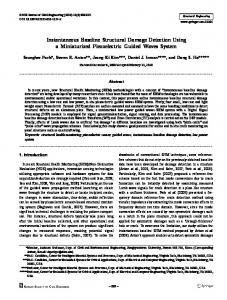
shows the layout of our network and also depicts the topology for the duration of the experiment. In the figure, dark solid arrows depict dominant links (links over which more than 40% of the packets were transmitted) to a Stargate, while dark dashed arrows depict the less frequently used links. Motes 9 and 13 used both the Stargates to send a significant fraction of the packets at different times during the experiment, while the other nodes were connected to only one of the Stargates for most of the time. The gray dashed arrows depict the links used in the lower-tier i.e., multi-hop routes among the Mica-Z motes. The bi-directional arrows indicate that the link shifted its direction during the experiment. The laptops and the StarGates communicated to each other using 802.11 radio in adhoc mode. We cannot currently induce damage on this large structure, so we tested a N ET SHM application that collects the impulse response of the entire structure. The application tasked the motes to collect data for 1 minute at 50Hz (3000 samples) while the structure was manually actuated to generate impulsive excitation. We time-stamped every sample as it was received at the application and measured latency as the time elapsed since the sensors completed the data. Figure 9 depicts the latencies incurred for transporting samples from each of the motes reliably to the PC. As one would expect, the latency increases linearly for successive samples, since all motes were rate-limited to 2 pkts/sec (each packet carried 8 samples). We also conducted a test to demonstrate the robustness of
the system by failing one of the Stargates. The latency of route recovery is depicted in Figure 10. Most motes incurred an increase in latency of about 30-100 seconds, some of which can be attributed to the route update interval, and some to packet loss recovery times. Eventually, all samples were recovered correctly at the base station. VI. C ONCLUSIONS AND F UTURE W ORK This paper is an attempt to move away from a vision of sensor networks as being necessarily application-specific. Our design and validation of N ET SHM suggests that, at least for a class of high-data rate applications, there exists an architecture that presents a fairly generic programming abstraction and where many systems components (routing, reliable transmission etc.) can be reused across applications. We conjecture that the N ET SHM architecture might be more broadly applicable to sensor networks in general, but have deferred an examination of this question to future work. R EFERENCES [1] F.-K. Chang, Ed., Structural Health Monitoring: The Demands and Challenges emph, Proceedings of the Third International Workshop on Structural Health Moni toring, Stanford University, 12-14 September 2001. CRC Press. [2] J. Caffrey, R. Govindan, E. Johnson, B. Krishnamachari, S. Masri, G. Sukhatme, K. Chintalapudi, K. Dantu, S. Rangwala, A. Sridharan, N. Xu, and M. Zuniga, “Networked Sensing for Structural Health Monitoring,” in International Workshop on Structural Control, New York,USA, June 2004. [3] J. P. Lynch, A. Sundararajan, K. H. Law, A. S. Kiremidjian, and E. Carryer, “Power-efficient data management for a wireless structural monitoring system,” in Proceedings of the 4th International Workshop on Structural Health Monitoring, vol. 1, Stanford, CA, September 15-17 2003. [4] J. P. Lynch, A. Sundararanjan, K. H. Law, A. S. Kiremidjian, E. Carryer, H. Sohn, and C. H. Farrar, “Field Validation of a Wireless Structural Monitoring System on the Alamosa Canyon Bridge,” in SPIE’s 10th Anuual International Symposium on Smart Structures and Materials, San Diego, CA, USA, March 2003. [5] N. Xu, S. Rangwala, K. Chintalapudi, D. Ganesan, A. Broad, R. Govindan, and D. Estrin, “A Wireless Sensor Network for Structural Monitoring,” in Proceedings of the ACM Conference on Embedded Networked Sensor Systems, Baltimore, MD, November 2004. [6] K. Mechitov, W. Y. Kim, G. Agha, and T. Nagayama, “High-Frequency Distributed Sensing for Structure Monitoring,” in Proc. First Intl. Workshop on Networked Sensing Systems (INSS 04), 2004. [7] H. Sohn and C. R. Farrar, “Damage Diagnosis Using Time Series Analysis of Vibration Signals,” Smart Material and Structures, vol. 10, no. 3, pp. 446–451, 2001. [8] P. Cawley and R. D. Adams, “The locations of Defects in Structures from Measurements of Natural Frequencies,” Smart Material and Structures, vol. 10, no. 3, pp. 446–451, 2001. [9] M. G. Srinivasan and C. A. Kot, “Effects of Damage on the Modal Parameters of a Cylindrical Shell,” in Proc. of the 10th International Modal Analysis Conference, 1992, pp. 529–535. [10] M. F. Elkordy, K. C. Chang, and G. C. Lee, “Neural Network Trained by Analytically Simulated Damage States,” ASCE Journal of Computing in Civil Engineering, vol. 7, no. 2, pp. 130–145, 1993. [11] S. W. Doebling, C. R. Farrar, M. B. Prime, and D. W. Shevitz, “Damage Identification and Health Monitoring of Structural and Mechanical Systems from Changes in their Vibration Characteristics: A Literature Review,” Los Alamos National Laboratory, Tech. Rep., May 1996. [12] F. E. Udwadia, “Some Uniqueness Results Related to Soil and Building Structural Identification,” SIAM Journal of Applied Mathematics, vol. 45, pp. 674–685, 1985. [13] O. S. Salawu, “Nondestructive assessment of structures using the integrity index method applied to a concrete highway bridge,” Insight, vol. 37, no. 11, pp. 875–878, 1995.
[14] J. N. Juang and R. S. Pappa, “An Eigen System Realization Algorithm for Modal Parameter Identification and Model Reduction,” Journal of Control Dynamics, vol. 8, pp. 620–627, 1985. [15] E. G. Straser and A. S. Kiremidjian, “A Modular, Wireless Damage Monitoring System,” John A. Blume Earthquake Engineering Center, Department of Civil and Environmental Engineering, Stanford University, Stanford, CA, USA, Tech. Rep., 1998. [16] K. Yao, R. Hudson, C. Reed, D. Chen, and F. Lorenzelli, “Blind Beamforming on a Randomly Distributed Sensor Array,” in IEEE Journal in Selected Areas in Communication, October 1998. [17] S. Ganeriwal, R. Kumar, and M. B. Srivastava, “Timing-sync protocol for sensor networks,” in Proceedings of the first international conference on Embedded networked sensor systems. ACM Press, 2003, pp. 138– 149. [18] M. Maroti, B. Kusy, and G. S. A. Ledeczi, “The flooding time synchronization protocol,” in Proceedings of the second international conference on Embedded networked sensor systems, 2004. [19] D. Estrin, R. Govindan, J. Heidemann, and S. Kumar, “Next Century Challenges: Scalable Coordination in Sensor Networks,” in Proceedings of the ACM/IEEE International Conference on Mobile Computing and Networking. Seattle, WA, USA: ACM, Aug. 1999. [20] C. Intanagonwiwat, R. Govindan, D. Estrin, J. Heidemann, and F. Silva, “Directed diffusion for wireless sensor networking,” ACM/IEEE Transactions on Networking, vol. 11, no. 1, pp. 2–16, February 2002. [Online]. Available: http://www.isi.edu/ johnh/PAPERS/Intanagonwiwat03a.html [21] P. Levis and D. Culler, “Mate : a tiny virtual machine for sensor networks,” in ASPLOS-X: Proceedings of the 10th international conference on Architectural support for programming languages and operating systems. ACM Press, 2002, pp. 85–95. [22] M. Welsh, “Exposing Resource Tradeoffs in Region-Based Communication Abstractions for Sensor Networks,” in Proceedings of the 2nd Workshop on Hot Topics in Networks (HotNets-II), November 2003. [23] P. Levis, N. Patel, D. Culler, and S. Shenker, “Trickle: A self-regulating algorithm for code propagation and maintenance in wireless sensor networks,” in First Symposium on Network Systems Design and Implementation, NSDI’04, March 2004. [24] J. Hui and D. Culler, “The Dynamic Behavior of a Data Dissemination Algorithm at Scale,” in Proceedings of the ACM Conference on Embedded Networked Sensor Systems, Baltimore, MD, November 2004. [25] M. Yarvis, N. Kushalnagar, H. Singh, A. Rangarajan, Y. Liu, and S. Singh, “Exploiting Heterogeneity in Sensor Networks,” in Proceedings of the IEEE Infocom, 2005. [26] V. Kottapalli, A. Kiremidjian, J. P. Lynch, E. Carryer, T. Kenny, K. Law, and Y. Lei, “A Two-Tier Wireless Sensor Network Architecture for Structural Health Monitoring,” in Proc. of SPIE’s 10th Annual Symposium on Smart Structures and Materials, San Diego, CA, March 2003. [27] “Mathworks inc.” http://www.mathworks.com/. [28] “Msc software corporation,” http://www.mscsoftware.com/. [29] “Moteiv inc.” http://www.moteiv.com/. [30] R. Szewczyk, A. Mainwaring, J. Polastre, J. Anderson, and D. Culler, “An analysis of a large scale habitat monitoring application,” in SenSys ’04: Proceedings of the 2nd international conference on Embedded networked sensor systems. ACM Press, 2004, pp. 214–226. [31] D. A. Maltz and D. B. Johnson, Mobile Computing. Kluwer Publishing, 1996, ch. Dynamic Source Routing in Ad-Hoc Wireless Networks. [32] “Nsf center for embedded networked sensing,” http://www.cens.ucla.edu/. [33] D. DeCouto, D. Aguayo, J. Bicket, and R. Morris, “A High Throughput Path Metric for Multi-hop Wireless Routing,” 2003. [34] A. Woo, T. Tong, and D. Culler, “Taming the Underlying Issues for Reliable Multihop Routing in Wireless Sensor Networks,” Los Angeles, CA, November 2003. [35] J. M. Caicedo, S. J. Dyke, and E. A. Johnson, “Natural Excitation Technique and Eigen System Realization Algorithm for Phase I of the IASC-ASCE Benchmark Problem: Simulated Data,” Journal of Engineering Mechanics, January 2004. [36] J. L. Beck and L. S. Katafygiotis, “Updating Models and Their Uncertainties I: Bayesian Statistical Framework,” Journal of Engineering Mechanics, vol. 124, no. 4, pp. 455–461, 1998.