KSCE Journal of Civil Engineering (2010) 14(6):889-895 DOI 10.1007/s12205-010-1137-x
Structural Engineering
www.springer.com/12205
Instantaneous Baseline Structural Damage Detection Using a Miniaturized Piezoelectric Guided Waves System Seunghee Park*, Steven R. Anton**, Jeong-Ki Kim***, Daniel J. Inman****, and Dong S. Ha***** Received December 8, 2009/Accepted February 23, 2010
···································································································································································································································
Abstract In recent years, new Structural Health Monitoring (SHM) methodologies with a concept of “instantaneous baseline damage detection” are being developed by many researchers since it has been found that the most of SHM technologies are too vulnerable to environmental and/or operational variations. In this context, this paper presents online instantaneous baseline structural damage detection using a low cost and low power, in-situ piezoelectric guided waves-SHM system. Firstly, four small, low cost and light weight smart Piezoelectric Ceramic (PZT) patches are surface-mounted and assumed to have the same bonding conditions to detect structural defects on an aluminum plate. Then, a miniaturized low power guided waves-SHM system with a Digital Signal Processing (DSP) module is employed for signal generation/excitation, signal sensing, and data processing. The instantaneous baseline damage detection based on Wavelet Transform (WT) and Cross Correlation (CC) analysis is carried out on the DSP module. Finally, effects of Lamb waves due to artificial ‘cut-damage’ at different locations are investigated using both “pitch-catch” and “pulse-echo” wave propagation schemes. Conclusively, this study shows a good potential for online and in-situ crack monitoring on panel structures such as an aircraft wing. Keywords: structural health monitoring, piezoelectric sensor, guided waves, instantaneous baseline damage detection, low power system ···································································································································································································································
1. Introduction In recent Structural Health Monitoring (SHM)/Non-Destructive Evaluation (NDE) applications, innovative sensing technologies utilizing appropriate software and hardware systems for data acquisition/reduction are strongly required (Heo and Jeon, 2009; Seo and Kim, 2008; Yun and Jang, 2008). Particularly, on the use of the guided wave propagation method launching an elastic wave through the structure to detect or locate incipient cracks, the changes in wave attenuation, time-delay, and/or reflection can be sensed by piezoelectric sensors-based structural monitoring system (Raghavan and Cesnik, 2007). However, there are significant technical challenges in realizing the pattern comparison. For instance, structural defects typically take place long after the initial baseline collected, and other operational and environmental variations of the system can produce significant changes in measured responses, masking potential signal changes due to structural defects (Sohn, 2007). To solve the
drawbacks of conventional SHM techniques, some referencefree schemes that do not rely on the previously obtained baseline data have been developed for damage detection in a structure (Anton et al., 2009; Kim and Sohn, 2007; Park et al., 2009). Particularly, Kim and Sohn (2007) proposed a reference-free scheme based on the fact that mode conversions due to crack formation can be instantly detected by examining measured Lamb wave signals for crack detection in a plate-like structure with a uniform thickness. Park et al. (2009) presented a frequency domain reference-free crack detection method using transfer impedances by extracting the mode conversion effects in frequency domain not time domain. However, since the mode conversion effects are caused by non-symmetric damages such as a notch in the plane structure, this approach could not be applied for symmetric damages such as a ‘through-thickness’ hole or crack. To overcome the limitation, our study utilizes the instantaneous baseline SHM method proposed by Anton et al. (2009). Anton’s approach enables us to detect symmetric damages
*Member, Assistant Professor, Dept. of Civil and Environmental Engineering, Sungkyunkwan University, Suwon 440-746, Korea (Corresponding Author, E-mail:
[email protected]) **Ph.D. Candidate, Center for Intelligent Material Systems and Structures, Dept. of Mechanical Engineering, Virginia Tech, Blacksburg, VA 24061, USA ***Ph.D. Candidate, Center for Embedded Systems for Critical Applications, Dept. of Electrical and Computer Engineering, Virginia Tech, Blacksburg, VA 24061, USA ****Professor, Center for Intelligent Material Systems and Structures, Dept. of Mechanical Engineering, Virginia Tech, Blacksburg, VA 24061, USA *****Professor, Center for Embedded Systems for Critical Applications, Dept. of Electrical and Computer Engineering, Virginia Tech, Blacksburg, VA 24061, USA − 889 −
Seunghee Park, Steven R. Anton, Jeong-Ki Kim, Daniel J. Inman, and Dong S. Ha
including a “through-thickness” cut without using any prior baseline information. On the use of the instantaneous baseline SHM method, a low-power piezoelectric guided waves system developed by Kim et al. (2009) is employed for this study. The miniaturized guided waves-SHM system with a Digital Signal Processing (DSP) module executes signal generation/excitation, signal sensing, and data processing. A Hanning windowed sinusoidal signal is applied to one PZT patch to generate Lamb waves that travel through the host structure, and then the propagating Lamb wave signals are captured at other PZT patches. The instantaneous baseline damage detection based on Wavelet Transform (WT) and Cross Correlation (CC) analysis is carried out by the DSP module of the low power piezoelectric guided waves system. Finally, the effects of Lamb waves due to artificial ‘cut-damage’ with different locations are investigated throughout both “pitch-catch” and “pulse-echo” wave propagation schemes on the instantaneous baseline damage detection method using a low power piezoelectric guided wave system. The current damage detection approach using the instantaneous baseline is applicable even under extreme environmental conditions and also very practical in an aspect of using a miniaturized low power and low cost guided waves system.
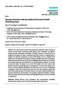
Fig. 1. A Low Power Piezoelectric Guided Wave System (Kim et al., 2009): (a) System Architecture, (b) Prototype
2. Low Power Piezoelectric Guided Waves System The architecture of our system, its operation, and excitation signal generation and processing of the sensed signal are presented in this section. 2.1 System Architecture and a Prototype A low-power piezoelectric guided wave SHM system has been recently developed by Kim et al. (2009). Our system consists of three major functional blocks: a processing unit, a signal actuation unit, and a signal sensing unit, as shown in Fig. 1. The processing unit is composed of a DSP Evaluation Module (EVM), specifically TMS320F2812 from Texas Instruments, and a memory unit. The processing unit controls the overall test procedure and performs signal generation and damage assessment. It also provides a communication interface to the host PC to record the sensed signal for post processing. The signal actuation unit consists of a Digital-to-Analog Converter (DAC) and a driver. The DAC with a 12-bit resolution and the maximum conversion rate of 100 MSPS generates an analog excitation signal. The driver made of opamps boosts the excitation signal up to 20 Vp-p , which increases the signal-to-noise ratio. Propagated Lamb waves are sensed at a PZT patch, and the signal amplified by an amplifier is applied to the Analog-to-Digital Converter (ADC) embedded in the DSP chip. The ADC has a 12-bit resolution and is configured to operate at 8.3 MSPS for our system. The sensed digital data is stored in the memory of the processing unit for further processing. A prototype of our system shown in Fig. 1(b) consists of three boards and has the dimension of 8.6 cm×13.5 cm×6.1 cm (W×L×H).
2.2 Wavelet-based Signal Processing The frequency of the excitation signal is chosen using the dispersion curve of Lamb waves for the structure under test. The shape of the excitation signal also plays an important role. A burst of a sine wave with Hanning window (equivalently raisedcosine with a roll-off factor one) is commonly used and adopted for our experiments. The waveform of the excitation signal is stored in a look-up table, and the DAC generates the excitation signal using the look-up table. The DAC operates at the sample rate of 100 MSPS, while the frequency of the excitation signal for our experiments is below 1 MHz. The driver with an inherent low-pass filter generates a smooth waveform owing to the relative high sampling rate of the DAC. Figs. 2(a) and (b) show a Hanning windowed excitation signal of 200 kHz in the time and frequency domains, respectively. Wavelet transform is applied to eliminate noise of the sensed Lamb wave ultrasonic signals (Legendre et al., 2000). Wavelet transform is computationally simple and provides a compact representation of a signal in the time and frequency domains. The wavelet transform used for our system is expressed as follows: 1 * t–u Wf ( u, s ) = ∫ f ( t ) ------ Ψ ⎛ ---------⎞ dt s ⎝ s ⎠
(1)
where, f(t) is the sensed waveform to be transformed and Ψ(t) is a mother wavelet with finite energy. Scale parameters s and u indicate dilation and shift, respectively. Any mother wavelet can be used for a wavelet transform, which is a major advantage of wavelet transform. The excitation signal itself is chosen as the
− 890 −
KSCE Journal of Civil Engineering
Instantaneous Baseline Structural Damage Detection Using a Miniaturized Piezoelectric Guided Waves System
Fig. 3. Instantaneous Baseline SHM Method Using Lamb Waves (Anton et al., 2009)
Fig. 2. Hanning Windowed Sine Wave with Four Peaks: (a) Waveform in the Time Domain, (b) Normalized Frequency Spectrum
mother wavelet and the dilation parameter s is set to 1, Then, Eq. (1) is simplified as: *
Wf ( u ) = ∫ f ( t )Ψ ( t – u ) dt
(2)
Eq. (2) suggests that the wavelet transform becomes the correlation between the excitation signal and the sensed signal. The resultant transformed waveform can be saved in the DSP EVM or the host PC for further processing.
baseline allowing the separation of damaged paths without prior knowledge of the structure by monitoring changes in the Lamb wave shape, magnitude, and frequency. In an anisotropic material, transducers must be placed such that the material properties of equal length paths are identical. If two sets of equal length paths do not have the same material properties, a separate analysis must be carried out for each set. Fig. 3 illustrates the concept of instantaneous baseline SHM where signals from undamaged paths are used to create an instantaneous baseline from which signals from damaged paths can be compared and signal differences are used to indicate damage. Finally, the differences are compared to threshold values that do not need to be calculated using baseline data. 3.2. Damage Detection Algorithm The damage detection algorithm utilized in this study involves the cross correlation analysis of each signal compared to the remaining signals of other equal length paths. Cross correlation analysis determines the degree to which two signals are linearly related. In order to detect damage in the test structures, the Cross Correlation (CC) value is used as a linear damage index and is defined as: 1- N --( x – x ) ( yi – y ) N∑ i = 1 i CC = ----------------------------------------------- = 1
3. Instantaneous Baseline SHM Techniques
σx σy
3.1 Instantaneous Baseline SHM using Lamb Waves The SHM technique employed in this study involves detecting damage without the use of prerecorded baseline data by acquiring an “instantaneous baseline” measurement each time a structure is interrogated (Anton et al., 2009). The transducers must be placed such that the sensor-actuator paths are of equal length and that structural features are spatially uniform between transducers. In an isotropic structure, the Lamb wave signals recorded for different paths will be identical if the structure is undamaged. If damage is present along one of the paths, the Lamb wave signal recorded along that path will differ from the remaining signals. Features from the undamaged paths are used to create a statistical Vol. 14, No. 6 / November 2010
(3)
Where, x and y are the mean values of the two sets of data and
σx and σx are standard deviations of the signature data sets x and
y, respectively. The more closely correlated the two signatures (therefore the healthier the system), the closer the CC is to the value 1. Therefore it is common to use “1-CC” instead of CC in order to have the damage index increase by increasing the severity of damage. The “1-CC” describes numerically how well a path correlates to all the other paths, where a path that does not correlate well to any other path will have a high value and a path that correlates well to all others will have a low value. The CC values are calculated for each path and the “1-CC” evaluation of the values is used as an instantaneous damage indicator to iden-
− 891 −
Seunghee Park, Steven R. Anton, Jeong-Ki Kim, Daniel J. Inman, and Dong S. Ha
Table 1. Instantaneous Damage Indicators from Every Path Combinations Instantaneous damage indicators
Path Combinations
1
“1-CC” between Paths #1 and #2
2
“1-CC” between Paths #1 and #3
3
“1-CC” between Paths #1 and #4
4
“1-CC” between Paths #2 and #3
5
“1-CC” between Paths #2 and #4
6
“1-CC” between Paths #3 and #4
*Note that Path #1 presents a signal from PZTs #1 to #2, Path #2 from PZTs #1 to #3, Path #3 from PZTs #2 to #4, and Path #4 from PZTs #3 to #4.
tify outlying or damaged paths. This algorithm involves calculating the “1-CC” values of a single reference path compared to all the other paths. Then, the single reference path is moved to the next path in a sequence. For instance, if four paths (Paths #1, #2, #3, and #4, herein, it is noted that Path #1 presents a signal from PZTs #1 to #2, Path #2 from PZTs #1 to #3, Path #3 from PZTs #2 to #4, and Path #4 from PZTs #3 to #4.) are considered, total six damage indicators can be instantaneously obtained from every path combinations (between Paths #1 and #2, #1 and #3, #1 and #4, #2 and #3, #2 and #4, and #3 and #4), as described in Table 1. Herein, when the first three instantaneous damage indicators 1, 2, and 3 all have bigger values than the maximum of the rest three other indicators 4, 5, and 6, one can predict the path #1 (which is common to all of the first indicators) is a crack located path. In a similar fashion, if the instantaneous damage indicators 2, 4, and 6 all have bigger values than the maximum of the other indicators 1, 3, and 5, then we can predict the path #3 (common to all of three indicators 2, 4, and 6) is a crack located path. Thus, the crack damage locations can be predicted simply by comparing their magnitudes between six instantaneous damage indicators. It is noted that the current damage detection algorithm does not require any prior information and does not rely on the previously obtained baseline data.
4. Proof-of-Concept Application 4.1 Experimental Setup A 91.44 cm×91.44 cm (3 ft×3 ft) and 1.59 mm (0.0625 in) thick 6061-T6 aluminum plate was selected as a test specimen (Fig. 4(a)). The health of the aluminum plate was monitored using four same PZT patches of 12.7 mm (0.5 in) diameter, 0.254 mm (0.01 in) thick circular PZTs from APC International, Ltd. with an array in a square grid pattern with 30.48 cm (12 inch) apart with each other as displayed in Fig. 4(b). The PZTs were attached to the plates by applying a single drop of Duro® super glue to the patch. Lamb waves are excited in a round robin fashion such that each PZT acts as both a sensor and an actuator. For example, PZT #1 will act as an actuator and excite a Lamb wave in the plate while the surrounding transducers (PZTs #2,
Fig. 4. Test Set-up: (a) Aluminum Plate (91.44 cm×91.44 cm×1.59 mm), (b) PZT Arrangement
#3, and #4) will act as sensors, recording response data. Then, PZT#2 will act as an actuator and the surrounding transducers will act as sensors. This process is repeated until Lamb waves traveling along each path will be all recorded. But, remember our damage detection algorithm considers only the paths have a same distance. Two artificial different damages shown in Fig. 5 are considered to test the instantaneous baseline Lamb waves SHM method. The first cut damage is inflicted at 10 cm apart from PZT #1 between PZT #1 and #2 to investigate the performance of the instantaneous baseline SHM method using “pitch-catch” scheme. (Fig. 5(a)). Then, the second damage is inflicted at 6 cm below PZT #4 along the extension of the path between PZT #2 and #4, and the damage is intended for testing “pulse-echo” scheme (Fig. 5(b)). The cuts in Figs. 5(a) and 5(b) are almost identical (through thickness cuts of 3 cm long and 1 mm wide) except their locations. 4.2 Sensor Diagnostics A critical element of most structural health monitoring systems is the ability to detect faulty sensors and actuators that may
− 892 −
KSCE Journal of Civil Engineering
Instantaneous Baseline Structural Damage Detection Using a Miniaturized Piezoelectric Guided Waves System
Fig. 5. Artificial Cut Damages Inflicted on the Plate (Through-thickness cuts of 3 cm long and 1 mm wide.): (a) Cut between PZT #1 and #2, (b) Cut below PZT #4
compromise damage detection performance. The instantaneous baseline method relies on the fact that signals recorded for undamaged paths are identical, thus sensor failure can cause faulty measurements and affect the ability to detect damage. In order to assess the condition of the piezoelectric sensors used for SHM, a technique developed by Park et al. (2006) known as piezoelectric active-sensor diagnostics is employed in this study. Piezoelectric sensor diagnostics is capable of evaluating both the bonding condition of the piezoelectric devices as well as the mechanical and electrical condition by monitoring the electrical admittance of bonded sensors. It has been demonstrated that sensor/actuator faults can be successfully detected by measuring the slope of the imaginary part of the admittance of each sensor over a wide range of frequencies. Changes in this slope are used to indicate broken or poorly bonded devices. When implementing the piezoelectric sensor diagnostics technique, it is desirable for all of the sensors to have admittance signatures with the same slope, and for that slope to be slightly lower than the admittance measured for a free (un-bonded) PZT patch. Prior to recording experimental data on the aluminum plate specimen, electrical admittance measurements are made to perform sensor diagnostics. Results of the admittance testing are given in Fig. 6. From the results, it can be seen that the slope of the imaginary part of
Fig. 6. Sensor Diagnostic Admittance Measurements Vol. 14, No. 6 / November 2010
the admittance of all four PZT patches shows little variation. This confirms that the sensors are properly bonded and free from fractures or defects. With four uniform and healthy sensors installed on the test plate, experimental testing can be carried out to validate the instantaneous baseline technique using low-power hardware.
5. Experimental Results The excitation signal for our experiments is a Hanning-windowed 200 kHz waveform with four cycles of the sinusoidal signal as displayed in Fig. 2(a). The excitation frequency of 200 kHz was chosen for a good separation of the fundamental symmetric mode S0 from the fundamental asymmetric mode A0. The excitation signal was applied to a PZT patch, and the response was captured at other PZT patches. Specifically, the response was sampled for 0.5 msec by the ADC with the sample rate of 8.3 MSPS and the resolution of 12 bits. Fig. 7(a) shows an intact waveform for the PZT #1 as an actuator and PZT #2 as a sensor (referred to as Signal 12). Fig. 7(b) is the wavelet profile,
Fig. 7. Waveforms Captured at PZT #2 with an Actuation at PZT #1 (Signal 12): (a) Raw Signal for the Path between PZT #1 and PZT #2 (Referred to as Signal 12), (b) Wavelet Profile for the Path between PZT #1 and PZT #2 − 893 −
Seunghee Park, Steven R. Anton, Jeong-Ki Kim, Daniel J. Inman, and Dong S. Ha
which suppresses noise and the DC offset of the original waveform. The first tone burst in Fig. 7 is the fundamental symmetric mode S0, and the second burst is the fundamental asymmetric mode A0. All other bursts are reflected modes from boundaries of the plate. 5.1 Pitch-Catch Scheme Firstly, the pitch-catch experiment was considered to diagnose the existence of the cut damage located between PZTs #1 and #2 shown in Fig. 5(a). Fig. 8 shows the successive measurements of all the Lamb wave paths with a same distance for the fundamental mode S0 under the cut damage. It is noticeable that the cut damage caused a time delay in the Signal 12 only (Fig. 8(a)). All other signals, Signals 13, 24, and 34 could be regarded as instantaneous baselines, and the damage indicators, “1-CC” values, described in Table 1 showed the cut damage detection results on the Path #1 (between PZTs #1 and #2) with the threshold set from the maximum of the instantaneous baselines (Fig. 8(b)). 5.2 Pulse-Echo Scheme Secondly, the pulse-echo experiment was considered to identify a cut damage located below PZT #4 shown in Fig. 5(b) without using any prior baseline information. It is noted that the damage under consideration is not on the path between the two PZT patches, which enables the pulse-echo scheme. Fig. 9(a)
Fig. 9. Instantaneous Baseline Cut Detection on Pulse-Echo Scheme, (a) Successive Captured Lamb Wave Signals, (b) Instantaneous Baseline Damage Detection
shows the successive measurements of all the Lamb wave paths with a same distance for the fundamental mode S0 under the cut damage. The reflected mode was observed in the Signal 24 only, and other signals, Signals 12, 13, and 34 were regarded as the instantaneous baselines. As shown in Fig. 9(b), it has been found that the cut damage below PZT #4 corresponding to Path #3 was successfully detected from the “1-CC” value chart calculated in Table 1 with a proper setting of the threshold value obtained from the instantaneous baselines.
6. Conclusions
Fig. 8. Instantaneous Baseline Cut Detection on Pitch-Catch Scheme: (a) Successive Captured Lamb Wave Signals, (b) Instantaneous Baseline Damage Detection
This paper presented online instantaneous baseline structural damage detection method using a low cost and low power, insitu piezoelectric guided waves-SHM system. A miniaturized low power piezoelectric guided waves-SHM system with a Digital Signal Processing (DSP) module was employed for signal generation/excitation, signal sensing, and data processing, and the instantaneous baseline damage identification algorithm based on Wavelet Transform (WT) and Cross Correlation (CC) analysis was applied on the DSP module. By using the instantaneous baseline damage indicators obtained between the signals successively measured at different paths with a same distance, no direct pattern comparison to pre-recorded baseline data was required to detect structural damages. In order to confirm all of the PZT
− 894 −
KSCE Journal of Civil Engineering
Instantaneous Baseline Structural Damage Detection Using a Miniaturized Piezoelectric Guided Waves System
sensors were surface-mounted with the same bonding condition, a sensor diagnostic has been carried out before the testing. Then, the ability of the instantaneous baseline method using a low power piezoelectric guided wave system has been investigated throughout both “pitch-catch” and “pulse-echo” wave propagation schemes to diagnose two cut damages with different locations. Conclusively, it has been verified that our integrated SHM method can successfully detect crack damages on uniform and isotropic aluminum plates without using any prior baseline information. Furthermore, it is noted again that the SHM method presented in this paper can be effectively utilized for real applications even under extreme environmental conditions because this approach does not need any prior baseline information. However, the current approach is applicable only for the damages located within the guided wave paths. More considerations to detect some damages inflicted out of the guided wave paths are required in the near future. Further work is underway to extend the current instantaneous baseline concept to more complicated structures containing complex geometry such as welds and joints.
Acknowledgements This study was supported by National Nuclear R&D Program (2010-0025889) and Basic Science Research Program (20100023404) through the National Research Foundation (NRF) funded by the Ministry of Education, Science and Technology of Korea, and u-City Master and Doctor Support Project funded by Ministry of Land, Transport and Maritime Affairs (MLTMA) of Korea. This all-out support is greatly appreciated.
References Anton, S. R., Inman, D. J., and Park, G. (2009). “Reference-free damage detection using instantaneous baseline measurements.” AIAA Journal,
Vol. 14, No. 6 / November 2010
Vol. 47, No. 8, pp. 1952-1964. Heo, G. and Jeon, J. (2009). “A smart monitoring system based on ubiquitous computing technique for infra-structural system: Centering on identification of dynamic characteristics of self-anchored suspension bridge.” KSCE Journal of Civil Engineering, Vol. 13, No. 5, pp. 333-337. Kim, S.-B. and Sohn, H. (2007). “Instantaneous reference-free crack detection based on polarization characteristics of piezoelectric materials.” Smart Materials and Structures, Vol. 16, No. 6, pp. 23752387. Kim, J.-K., Zhou, D., Ha, D., and Inman, D. J. (2009). “A practical system approach for fully autonomous multi-dimensional structural health monitoring.” Proceedings of SPIE Symposium on Smart Structures and Materials & Nondestructive Evaluation and Health Monitoring, San Diego, CA, USA, March. Legendre, S., Massicotte, D., Goyette, J., and Bose, T. K. (2000). “Wavelet-transform-based method of analysis for lamb-wave ultrasonic NDE signals.” IEEE Trans. on Inst. and Meas., Vol. 49, No. 3, pp. 524-530. Park, G., Farrar, C., Rutherford, A., and Robertson, A. (2006). “Piezoelectric active sensor self-diagnostics using electrical admittance measurements.” Journal of Vibration and Acoustics, Vol. 128, No. 4, pp. 469-476. Park, S., Lee, C.-G., and Sohn, H. (2009). “Reference-free crack detection using transfer impedances.” Journal of Sound and Vibration, Vol. 329, No. 12, pp. 2337-2348. Raghavan, A. and Cesnik, C. E. S. (2007) “Review of guided-wave structural health monitoring.” The Shock and Vibration Digest, Vol. 39, No. 2, pp. 91-114. Seo, Y. and Kim, Y. R. (2008) “Using acoustic emission to monitor fatigue damage and healing in asphalt concrete.” KSCE Journal of Civil Engineering, Vol. 12, No. 4, pp. 237-243. Sohn, H. (2007). “Effects of environmental and operational variability on structural health monitoring.” Phil. Trans. R. Soc. A., Vol. 365, No. 1851, pp. 539-560. Yun, Y.-W. and Jang, I.-Y. (2008). “Research on early age deformation of high performance concrete by fiber bragg grating sensor.” KSCE Journal of Civil Engineering, Vol. 12, No. 5, pp. 323-328.
− 895 −