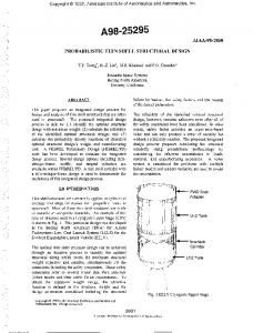
A deployable CFRP thin shell reflector is being developed for future earth observation ... frequency, quasi-static acceleration, sine vibration and shock analyses ...
AIAA 2016-2169 AIAA SciTech 4-8 January 2016, San Diego, California, USA 3rd AIAA Spacecraft Structures Conference
Structural Dynamic Response of Deployable Thin Shell Reflector in Folded Configuration
Downloaded by ROKETSAN MISSLES INC. on June 7, 2016 | http://arc.aiaa.org | DOI: 10.2514/6.2016-2169
O. Soykasap1 , S. Karakaya2, A. Gayretli3, Y. Akcin4 Afyon Kocatepe University, Afyonkarahisar, Turkey, 03200
A deployable CFRP thin shell reflector is being developed for future earth observation missions. Preliminary design shows that it has a high stiffness/mass ratio when deployed, and has potential for further development in order to meet the requirements of harsh environment during launch and in orbit. Hence the study is focused on the structural dynamic analysis of the reflector in folded configuration. The structural dynamic response of the folded reflector is obtained by a whole host of analyses including folding, natural frequency, quasi-static acceleration, sine vibration and shock analyses considering launch mechanical environment.
A. Nomenclature CFRP CTE D E1 E2 F/D G12 LEO RMS RF
= = = = = = = = = =
S L
= longitudinal tensile strength
S L
= longitudinal compressive strength
S T S T SLT SBR SSBR TDRS 12 21
carbon fiber reinforced plastic coefficient of thermal expansion diameter longitudinal elastic modulus transverse elastic modulus focal length to diameter ratio shear modulus low earth orbit root mean square radio frequency
= transverse tensile strength = = = = = = =
transverse compressive strength shear strength spring back reflector stiffened spring back reflector tracking and data relay satellite major Poisson’s ratio minor Poisson’s ratio
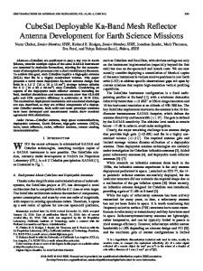
I. Introduction A deployable CFRP thin shell reflector is being developed at Afyon Kocatepe University, Turkey for future earth observation missions using X-band satellite.1-2 The reflector is rolled in a compact volume with high efficiency of packaging compared to the state of the art foldable shell reflector of Tracking and Data Relay Satellite (TDRS) of NASA. The initial configuration of the reflector is based on offset SSBR concept with a diameter of 3 m. It is made 1
Prof.Dr, Material Science and Engineering, ANS Campus, AIAA Senior Member. Assoc.Prof.Dr., Mechanical Engineering, ANS Campus. 3 Assoc.Prof.Dr., Mechatronics Engineering, ANS Campus. 4 Research Assistant, Metallurgical and Materials Engineering, ANS Campus. 1 American Institute of Aeronautics and Astronautics 2
Copyright © 2016 by Omer Soykasap, Sukru Karakaya, Ahmet Gayretli, Yelda Akcin. Published by the American Institute of Aeronautics and Astronautics, Inc., with permission.
Downloaded by ROKETSAN MISSLES INC. on June 7, 2016 | http://arc.aiaa.org | DOI: 10.2514/6.2016-2169
of CFRP material with a thickness of 0.33 mm for the shell surface. Preliminary design study shows that it has a high stiffness/mass ratio when deployed, and has potential for further development in order to meet the requirements of harsh environment during launch and in orbit. Hence the study is focused on the structural dynamic analysis of the reflector for launch environment. The reflector is subjected to static and dynamic loads during ground operations and flight. Such loads may be due to transportation loads, aerodynamic loads such as wind, gusts, buffeting, propulsion loads such as longitudinal acceleration, thrust buildup, couplings such as structure-fluid, structurepropulsion loads, etc. These must be studied during design phase. The aim of the paper is to obtain the structural dynamic response of the folded reflector by a whole host of analyses including folding, natural frequency, quasistatic acceleration, sine vibration and shock analyses considering launch mechanical environment. Section II describes structural dynamic analysis of the thin shell reflector. First the initial design of the reflector is given; next folding analysis, development of hold-down and release mechanism, natural frequency, quasi-static acceleration, sine vibration and shock analyses are explained and the results of the analyses are preented. Section III discusses the results and concludes the paper.
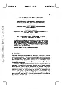
II. Structural Dynamic Analysis A. Initial Design The concept is based on the SSBR concept3, but it introduces substantial improvements for manufacturing, higher stiffness to mass ratio and lower cost by considering the design changes for reinforcements of the reflector surface.2 The reflector has D=3 m, F/D=0.6 and with an offset of 0.3 m. It is a simple monolithic structure, and it consists of a reflector surface and a flat skirt. Reinforcements in the central region are needed for enhanced rigidity where the structure attached to the spacecraft platform via the limb and hinge mechanisms. The reflector is made of thin CFRP material that can take high strains during folding, and can still deploy itself by the stored elastic energy in the material. The shell surface is reinforced at central region and along the rim. The thickness of the shell surface varies along the radial direction: eight layers [0/45] 2s within diameter of D1, five layers [0/453/0] between D1 and D2, three layers [0/45/0] between D2 and D3, and two layers [0/45] for the rest, where D1=300 mm, D2=600 mm, D3=900 mm. The skirt has a width of 0.1 m and three layers [0/45/0] as seen in Fig.1. Main requirements include a reflector diameter of 2-3m, a packaged volume with a diameter of 1m and a length of 3 m, a natural frequency during launch in folded configuration 40 Hz, no material failure during folding and deployment and also for vibration and acoustic loads during launch (sine loading with varying frequency and 144 dB), RMS surface error 0.6 mm, subject to absolute temperature in orbit (-180°C; +110°C) and a gradient of 100°C along aperture, high deployed stiffness/mass ratio with natural frequency 1 Hz and with areal density 1.5 kg/m2 in deployed configuration. For initial design, a plain weave standard-modulus CFRP with a ply thickness of 0.11 mm is considered. The material properties are as follows: E1=E2=53.7 GPa, G12=2.85 GPa, 12=21=0.15. The model is then modeled in ABAQUS finite element program. According to the results, the fundamental natural frequency is 4.5 Hz, and the mass of the reflector is 3.1 kg (areal density of 0.44 kg/m2), which satisfies the requirements. The initial reflector configuration is still being optimized for the structural response considering higher modulus material, stiffness/mass ratio, buckling due to gravity, thermal distortions in deployed configuration, and material failure during folding. B. Folding Analysis of Reflector Folding of the reflector is carried out by geometrically nonlinear quasi static analysis. Initial studies show that the reflector can be fold in two different ways. First one is to roll two opposite edges toward the center separately, and the other one is to roll the two opposite edges so that one ends up inside the other. It is found that the latter is better solution resulting lesser strains in folded configuration and hence would yield less creep due to holding the reflector in folded configuration for a while for launch. The structure is fixed in the center within a diameter of 0.3 m. In order to fold the structure, prescribed rotations are applied to the parabolic curved lines A and B defined on the surface of the reflector running from the tip to the center as seen in Fig.2. The curved lines have a projected length of 1 m in XZ plane. The equal and opposite linearly varying rotations, which is 2.4 rad at the tip and 0.4 rad at the other end, are applied to the curves using analytical field option. The prescribed rotation boundary conditions are better than the prescribed moments for folding because the moments vary during folding, which are unknown beforehand due to varying stiffness of the structure. 2 American Institute of Aeronautics and Astronautics
Downloaded by ROKETSAN MISSLES INC. on June 7, 2016 | http://arc.aiaa.org | DOI: 10.2514/6.2016-2169
a)
b)
c) Figure 1. Initial Design of high strain shell reflector a) and b) deployed reflector attached to the spacecraft bus, c) finite element model.
Figure 2. The boundary conditions for folding: fixed in the center and prescribed rotations along curved lines A and B.
3 American Institute of Aeronautics and Astronautics
The material failure is estimated during folding by Tsai-Wu damage criterion as calculated as follows
Downloaded by ROKETSAN MISSLES INC. on June 7, 2016 | http://arc.aiaa.org | DOI: 10.2514/6.2016-2169
F11 12 F22 22 F66 62 F1 1 F2 2 2F12 1 2 1
(1)
where , , , , , and . and are longitudinal tensile and compression strength; and are transverse tensile and compression strength; is shear strength. Both compression strengths are taken as positive. The analysis is performed for an intermediate modulus material of IM7/8552 plain-weave composite. The results are expected to be conservative for the standard modulus material. The typical properties are E1=E2=90.6 GPa, G12=5.3 GPa, 12=21=0.032, = =1090 MPa, = =945 MPa and =88 MPa. The results are given for the external surface of the structure in Fig.3. According to the results, the highly stressed regions are located at the center, where the reflector is fixed, and the tip of the reflector where the skirt starts with a discontinuity of the curvature. Yet, there is not any failure observed on the structure. The folded reflector can fit into a cylindrical volume with a diameter of 0.7 m and a length of 3m.
Figure 3. Analysis results of rolled reflector (I top, II bottom and III left views).
C. Development of Hold-Down and Release Mechanism and Modal Analysis of Folded Reflector The reflector must have enough stiffness after folding for launch in order to avoid possible resonance due to launch vehicle loads. As a requirement, the fundamental frequency of the folded reflector for a global mode must be ≥ 40 Hz. The modes with effective modal mass less than 5% is taken to be local modes. Initially it is envisioned that the folded structure is held down by only a cable tie and attached to the satellite platform in the middle, as shown in Fig.4. According to the analysis, the fundamental frequency is 3.78 Hz, which is very low. The requirement is not satisfied because the unsupported ends play a significant role in the global modes as seen in Fig.5. Hence additional boundary conditions at two ends are needed in order to achieve the requirement. Then the both ends are fixed at three black dots along the rim of the reflector as seen in Fig.6 or alternatively it is fixed along the black line completely as seen in Fig.7. A stiff frame or a foam roller can be placed inside the structure to provide such boundary conditions.
4 American Institute of Aeronautics and Astronautics
Downloaded by ROKETSAN MISSLES INC. on June 7, 2016 | http://arc.aiaa.org | DOI: 10.2514/6.2016-2169
Figure 4. The reflector packed, tied with a cable and fixed to satellite platform in the middle.
Figure 5. The natural frequency modes of folded reflector held by a cable.
Figure 6. Boundary conditions on folded reflector (fixed at black points along the rim). Modal analysis is performed immediately afterwards the quasi-static folding. The mode shapes are obtained for both boundary conditions and given in Figs.8 and 9 whereas corresponding effective modal masses are given in Tables 1 and 2. As seen in Table 1, when the reflector is fixed at three locations along the rim at the ends, the effective masses of the first two modes are less than 5% corresponding to local modes as seen in Fig.8. However 3rd and 4th modes are global modes with the natural frequency still being less than 40 Hz. It is concluded that it does not 5 American Institute of Aeronautics and Astronautics
Downloaded by ROKETSAN MISSLES INC. on June 7, 2016 | http://arc.aiaa.org | DOI: 10.2514/6.2016-2169
satisfy the requirement. On the other hand, when the reflector is fixed at both ends, there is no global mode below 40 Hz as seen in Fig.9, hence that satisfies the requirement.
Figure 7. Boundary conditions on folded reflector (fixed along the black lines and at the center).
Figure 8. Mode shapes of the folded reflector (fixed at three locations along the rim at the ends and at the center).
Figure 9. Mode shapes of the folded reflector (fixed completely along the rim at the ends).
6 American Institute of Aeronautics and Astronautics
Table 1. Modal analysis of the folded reflector (fixed at three locations along the rim at the ends). Effective modal mass (%)
Downloaded by ROKETSAN MISSLES INC. on June 7, 2016 | http://arc.aiaa.org | DOI: 10.2514/6.2016-2169
Mod
Frequency (Hz)
Xtranslation
Ytranslation
Ztranslation
Xrotation
1 20.80 0.02 0.36 0.00 0.04 2 33.51 0.42 2.55 0.00 0.02 3 34.69 0.67 22.27* 0.00 0.00 4 38.32 4.77 12.42 0.00 0.04 5 42.12 0.26 2.13 0.00 0.08 6 44.79 4.75 0.04 0.00 0.13 7 45.22 5.06 0.15 0.00 0.08 8 47.32 8.46 0.24 0.00 0.05 9 47.81 1.74 9.48 0.00 0.17 10 49.51 2.47 0.00 0.00 0.10 Total mass: 4.538 kg, *: There is an important translation in the direction of Y
Yrotation
Zrotation
0.00 0.01 0.01 0.01 0.00 0.01 0.01 0.18 0.01 0.01
0.08 1.66 6.72 11.12 0.17 1.46 5.10 2.57 0.13 3.66
Table 2. Modal analysis of the folded reflector (fixed completely along the rim at the ends). Effective modal mass (%) Mod
Frequency (Hz)
1 29.18 2 46.36 3 58.16 4 63.19 5 64.52 6 69.17 7 71.06 8 73.43 9 73.60 10 76.73 Total mass: 4.538 kg
Xtranslation
Ytranslation
Ztranslation
Xrotation
Yrotation
Zrotation
0.02 0.00 0.05 0.03 0.07 0.25 0.11 0.04 0.00 0.01
0.03 0.69 0.02 0.09 0.01 2.69 0.09 0.23 0.08 0.03
0.00 0.00 0.00 0.00 0.00 0.00 0.00 0.00 0.00 0.00
0.03 0.11 0.07 0.00 0.01 0.02 0.06 0.09 0.05 0.19
0.00 0.00 0.00 0.00 0.01 0.00 0.00 0.00 0.00 0.01
0.02 0.09 0.01 0.08 0.03 0.62 0.10 0.14 0.00 0.02
Although fixing the folded reflector at both ends satisfies the requirement, it is problematic to manufacture a corresponding hold-down and release mechanism using frame or foam roller placed inside the structure. This mechanism must also be compliant with deployment and be removed afterwards. Further precautions must be considered to fix the mechanism to the platform in order not to leave space debris after deployment. Therefore a new hold-down and release mechanism is designed. The rolled reflector is held down with three ring clamps; one of them placed in the middle and two of them placed near the ends as seen in Fig.10. The clamps have a width of 80 mm, a thickness of 40 mm and a diameter of 700 mm. The clamps are fixed to a longitudinal strip with one face being flat and the other face being curved with the same curvature of the clamps. The strip has a width of 200 mm, and varying thickness (maximum of 56.25 mm and minimum of 50 mm). The strip is attached to the representative satellite platform in middle region with a rectangular area of 200 mm×415 mm.
7 American Institute of Aeronautics and Astronautics
Downloaded by ROKETSAN MISSLES INC. on June 7, 2016 | http://arc.aiaa.org | DOI: 10.2514/6.2016-2169
Figure 10. Deployed reflector (top), hold-down concept of the folded reflector (middle and bottom).
During deployment, first the reflector starts to deploy by releasing the clamps simultaneously. Once they are released completely, the arm with three limbs starts to rotate the folded reflector into the final deployment position. Finally, the reflector deploys itself by the stored elastic energy in the structure after cutting the cable by pyro technics. Similar hold-down concept of AstroMesh Antenna is flight proven, in which the antenna stows like a closed umbrella and deploys on a huge boom.4 The hold-down and release mechanism can be produced using CFRP composites, sandwich composites or light weight metal alloys. In the analysis, it is assumed that it is made of quasiisotropic material. The material properties are as follows: E=60 GPa, Poisson’s ratio=0.28, density=1000 kg/m3. These properties can be obtained using triaxial woven CFRP material. The reflector is fixed by the clamps and 8 American Institute of Aeronautics and Astronautics
Downloaded by ROKETSAN MISSLES INC. on June 7, 2016 | http://arc.aiaa.org | DOI: 10.2514/6.2016-2169
attached to the arm in the center with a diameter of 300 mm. The modal analysis is performed and the mode shapes are given in Fig.11. The fundamental frequency is 147.2 Hz, which satisfies the requirement. The local mode shapes occurs at the unsupported free ends of the reflector.
MODE I=142.7 Hz
MODE I=145.1 Hz
MODE II=144.2 Hz
MODE II=147.5 Hz
Figure 11. Natural frequency modes of packed reflector.
D. Quasi-Static Accelerations The reflector is subjected to static and dynamic loads during ground operations and flight. Such excitations may be due to transportation, aerodynamic and propulsion loads. These must be studied during design phase. For this analysis, it is necessary to know type of launch vehicle and corresponding load conditions. In this study, Ariane Vega launch vehicle is selected as an affordable launch solution for LEO earth observation mission.5 The payload fairing of Vega has a diameter of 2.6 m and a length of 7.88 m. It is considered that the folded reflector is held down to satellite body in Z direction where the longitudinal axis of the reflector is parallel to the longitudinal axis of the launcher. It is envisaged that the fairing volume is adequate to put the satellite inside. Since the folding of the reflector results like a cylinder with about a diameter of 0.7m and a length of 3m, it seems that the best solution is to put the reflector longitudinally. Otherwise it may be necessary to use a launcher with larger payload diameter. Typical longitudinal static accelerations during launch of Ariane Vega are given in Fig.12. According to the figure, maximum acceleration load is about 5.2 G. The highest longitudinal acceleration occurs just before the thirdstage cutoff. However this load occurs at the interface between the launcher and the spacecraft. Therefore a greater design load about 12 G is taken into consideration. The load is applied in –Z direction, and the static analysis is performed when the reflector is held down in folded configuration as given in Fig.13. The critical areas for material failure are investigated with Tsai-Wu failure criterion. The contours of the criterion are given in Fig.14. According to the results, the maximum of the criterion is quite low from the failure value of one, so there is plenty of a safety margin. 9 American Institute of Aeronautics and Astronautics
Downloaded by ROKETSAN MISSLES INC. on June 7, 2016 | http://arc.aiaa.org | DOI: 10.2514/6.2016-2169
Figure 12. Longitudinal static acceleration of Ariane Vega during launch.5
Figure 13. Static acceleration applied along -Z direction.
10 American Institute of Aeronautics and Astronautics
Downloaded by ROKETSAN MISSLES INC. on June 7, 2016 | http://arc.aiaa.org | DOI: 10.2514/6.2016-2169
Figure 14. The contours of Tsai-Wu failure criterion after 12 G acceleration.
E. Sinusoidal Vibrations According to ECSS-E-10-03B standard, sinusoidal qualification test levels are given in Table 3. This test levels are determined by ESA and applied for equipment with fundamental frequency > 100 Hz and mass ≤ 50 kg as a general test level6. Steady-state dynamic vibration analysis is used for this analysis. The structure must sustain the loads specified in the table, i.e. no material failure. The specified loads are applied respectively as base motion in Z direction. The Mises stress results are given in Figs. 15-20. For the frequency range of 5-21 Hz and 11 mm displacement, the stress levels are very low around 1.7 MPa as given in Fig.15. Figure 16 shows the variation of maximum stress of a critical node on the reflector vs. frequency. The higher the frequency is, the higher stress occurs. Similarly, the stress contours of the structure at 65 Hz and 20 G acceleration and at 105 Hz and 6 G acceleration are given in Figs. 17 and 19, respectively. Frequency vs. stress curves at a critical node on the reflector between 25-65 Hz and 65-105 Hz are given in Figs. 18 and 20, respectively. According to the analyses, the stress levels are low for sinusoidal vibrations, and there are plenty of safety margins. Table 3. Sinusoidal qualification test levels for equipment (for first frequency> 100 Hz and mass ≤ 50 kg).6 Frequency
Level
Sign
5-21 Hz
11 mm (0- peak)
No notching
21-60 Hz
20 G (0- peak)
60-100 Hz
6 G (0- peak)
11 American Institute of Aeronautics and Astronautics
Downloaded by ROKETSAN MISSLES INC. on June 7, 2016 | http://arc.aiaa.org | DOI: 10.2514/6.2016-2169
Figure 15. Stress contours in the structure at 25 Hz and 11 mm displacement in harmonic vibration.
Figure 16. Frequency vs. stress at critical node on the reflector (0-25 Hz).
12 American Institute of Aeronautics and Astronautics
Downloaded by ROKETSAN MISSLES INC. on June 7, 2016 | http://arc.aiaa.org | DOI: 10.2514/6.2016-2169
Figure 17. Stress contours in structure at 65 Hz and 20 G acceleration in harmonic vibration.
Figure 18. Frequency vs. stress curve at critical node on the reflector (25-65 Hz).
13 American Institute of Aeronautics and Astronautics
Downloaded by ROKETSAN MISSLES INC. on June 7, 2016 | http://arc.aiaa.org | DOI: 10.2514/6.2016-2169
Figure 19. Stress contours in structure at 105 Hz and 6 G acceleration in harmonic vibration.
Figure 20. Frequency vs. stress at critical node on the reflector (65-105 Hz).
F. Shock Response Analysis The spacecraft is subject to shock accelerations due to separation of stages, fairing jettisoning and spacecraft separation. These accelerations may cause damage of spacecraft and its components. For the Vega launch vehicle, the envelope of shock response spectrum in terms of frequency vs. acceleration at the spacecraft base is given in Fig. 21. These levels are applied simultaneously in axial and radial directions. To determine the shock effect originated from launching on the reflector structure, shock response analysis using the natural frequency modes is performed for the specified spectrum. The analysis obtains a linear response of the structure for each frequency and 14 American Institute of Aeronautics and Astronautics
Downloaded by ROKETSAN MISSLES INC. on June 7, 2016 | http://arc.aiaa.org | DOI: 10.2514/6.2016-2169
corresponding shock level in the spectrum, and then the maximum response is obtained for the whole spectrum. Since this is based on the convergence of the results with a relatively low computation cost, linear response analysis may be beneficial for only preliminary design. Typical damping values for spacecraft structures are between 0.5% and 5%7, and hence structural damping for all modes is taken to be 2% in the analysis. This spectrum is applied in each direction synchronously. The maximum stress contour after the analysis is given Fig. 22. The high stress regions are localized near the free end of the reflector while the rest of the structure has relatively lower stress.
Figure 21. Shock spectrum of the Vega launch vehicle.5
Figure 22. The stress contours after shock analysis.
15 American Institute of Aeronautics and Astronautics
Downloaded by ROKETSAN MISSLES INC. on June 7, 2016 | http://arc.aiaa.org | DOI: 10.2514/6.2016-2169
III. Conclusion This study presents the results of a whole host of structural dynamic analyses of the folded reflector including folding analysis, natural frequency analysis, quasi-static acceleration analysis, forced sine vibration analysis and shock analysis. For the folding analysis, the reflector is folded by rolling the two opposite edges so that one ends up inside the other like a cylinder with about a diameter of 0.7m and a length of 3m. According to the results, the stressed regions are localized at the center where the reflector is fixed and the tip of the reflector where the skirt starts with a discontinuity of the curvature. Yet, there is not any damage on the structure. Hold-down and release mechanism is developed under the requirement of fundamental frequency ≥40 Hz, which is a challenging the requirement because the reflector is made of very thin material. First this is studied by holding the reflector in folded configuration only a cable in the middle and later more fixing is needed at the both ends to satisfy the requirement. Due to manufacturing issues of such a mechanism, a new compliant holddown and release mechanism is developed. The reflector is held down by three ring clamps and a cable. During deployment, the clamps are released; the arm rotates the folded reflector into a final deployment position and the reflector deploys itself by the stored elastic energy in the structure by after cutting the cable by pyro technics. In this study Ariane Vega is selected as a launch vehicle. Structural dynamic response of the reflector is obtained for the mechanical environment of Vega. According to the quasi-static acceleration analysis, the stress levels are quite low. For the sinusoidal vibrations, the stress levels are again low for the qualification test levels. Last the shock response analysis is carried out for the specified shock spectrum. The results show that high stress regions are localized near the free end of the reflector while the rest of the structure has relatively lower stress. In order to reduce the stress level of the shock a ticker material along the rim must be considered. The whole host of analyses shows that the thin shell reflector has good potential to meet the challenging requirements during launch.
Acknowledgments This study is supported by the Undersecretariat for Defence Industries (SSM) of Turkey and ASELSAN.
References 1 Soykasap, O., Karakaya, S., Gayretli, A., Akcin Y., “Conceptual Design of Deployable Composite Reflector for an X-band Satellite Payload,” Proceedings of 2th International Scientific Conference on Advanced Lightweight Structures and Reflector Antennas, Tbilisi, Georgia, October 1– 13, 2014, pp.254--263. 2 Soykasap, O., Karakaya, S., Gayretli, A., Akcin Y., “Preliminary Design of Deployable Flexible Shell Reflector of an Xband Satellite Payload,” Proceedings of the AIAA SciTech, 2nd AIAA Spacecraft Structures Conference, Kissimmee, Florida, USA, 5-9 January 2015, AIAA Paper 2015-0945. 3 Soykasap, O. and Tan, L.T, “High Precision Offset Stiffened Spring-Back Composite Reflectors,” AIAA Journal, Vol.49, No.10, 2011, pp.2144-2151. 4 http://advancedtextilessource.com/2015/02/mesh-lasso-rounds-up-data-in-space/, Access Date: 18.09.2015 5 http://www.arianespace.com/launch-services-vega/Vega-Users-Manual_Issue-04_April-2014.pdf, Access Date 18.09.2015 6 ECSS-E-10-03B Draft 2, Space engineering, 29 January 2008, http://www.ecss.nl/forums/ecss/dispatch.cgi/home/showFile/100688/d20080131141407/No/ecss-e-10-03BDraft2(29Jan2008).pdf, Access Date: 20.11.2015 7 Degener, M., “Effect of Structural Damping on the Dynamic Response of Spacecraft,” Proceeding of 48th Meeting of the AGARD Structures and Materials Panel, AGARD-CP-277: Damping Effects in Aerospace Structures, Williamsburg, VA, USA, 2-3 April 1979.
16 American Institute of Aeronautics and Astronautics