Open Access Database www.i-techonline.com. Source: Simulated Annealing, Book edited by: Cher Ming Tan, ISBN 978-953-7619-07-7, pp. 420, February 2008 ...
14 Structural Optimization Using Simulated Annealing Fazil O. Sonmez
Department of Mechanical Engineering Bogazici University Turkey
Open Access Database www.i-techonline.com
1. Introduction The increasing demand from the industry for lightweight, high-performance and low-cost structures drives the considerable current research going on in the field of structural optimization. In the early stages, structural optimization was restricted to sizing optimization. Now, there are broadly three problem areas that the researchers and engineers face. One is shape optimization, which involves finding the best profile for a structure under various constraints imposed by the requirements of the design. The objective may be to minimize weight or maximize mechanical performance. The other is topology optimization, which involves finding the best configuration or layout for a structure. The last one is composites optimization. Better performance may be obtained by optimizing the material system itself such as fibre orientations, filler or fibre volume fraction, ply thickness, stacking sequence. Locating globally optimum structural designs is a difficult problem, requiring sophisticated optimization procedures. In typical structural optimization problems, there may be many locally optimal configurations. For that reason, a downhill-proceeding algorithm, in which a monotonically decreasing value of objective function is iteratively created, may get stuck into a locally optimal point other than the globally optimal solution. Therefore, researchers adopted global search algorithms like simulated annealing in their studies of structural optimization. This chapter gives a review of the current research on these fields. The objective functions, constraints, design variables and search algorithms adopted in these studies will be discussed. Then, this chapter will focus on the applications of simulated annealing to structural optimization.
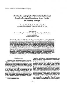
2. Shape optimization In shape optimization, contours of a structure are modified to achieve savings in weight and improvements in structural performance. Fig. 1 depicts a typical shape optimization problem. This is an eccentrically loaded plate restrained at one end and loaded at the other. The shape of the boundary excluding the portion on which boundary conditions are applied is optimized for minimum weight. Source: Simulated Annealing, Book edited by: Cher Ming Tan, ISBN 978-953-7619-07-7, pp. 420, February 2008, I-Tech Education and Publishing, Vienna, Austria
282
Simulated Annealing
F F Initial shape
Optimal shape
Fig. 1. An illustration of a shape optimization problem. Applications in this field include optimum shape designs of 2D structures like eccentrically loaded plates as depicted in Fig. 1, fillets, cams, torque arms, pin joints, brackets, (see Fig. 2. a, b, c, d, e), hooks, holes in plates, rings, chain links, plates containing cracks, saw blades etc, beams, tubes, shell structures, components in contact, thermal fins, axisymmetric structures, 3D structures like engine bearing cap, turbine blades (see Fig. 2. f), engine mount bracket, (see Fig. 2. g) and slider bearings (see Fig. 2. h). In any optimization process, there should be an objective function according to which effectiveness of a design can be evaluated. In shape optimization, either the most efficient use of material or the best performance is sought. The goal may be to minimize weight of a structure or to increase mechanical performance, e.g. to minimize stress concentration, peak contact stress, compliance etc.; or maximize static strength, fracture strength, buckling strength, fatigue life etc. In order for a designer to optimize a structure, he/she should be allowed to change some of its properties affecting the objective function. As for a shape optimization problem, some parts of the boundary should be allowed to vary. Boundaries of structures may be defined using spline curves passing through a number of key points. Coordinates of these points thus become design variables. By changing the positions of the key points during an optimization process, a new shape can be obtained (Fig. 3). The advantage of using spline curves is that the shape of a structure can be defined using just a few design variables and a smooth boundary is obtained. Some parameterized equations can also be used for boundary curve; the parameters then control the size, shape, and aspect ratio of the boundary. Alternatively, simply dimensions of individual parts of the structures, radius of a hole, length of an edge etc., can be taken as design variables; but the number of configurations that can be generated may be too limited for efficient optimization. Also, by removing or restoring materials within the elements of a finite element model, the shape of a structure may be changed. In that case, presence of material becomes a design variable. In this approach, a structural model is first divided into small finite element blocks and then these blocks are removed or restored to obtain a new shape (Fig. 4). One difficulty with this method is that removing and restoring an element may violate model connectivity.
283
Structural Optimization Using Simulated Annealing
Whenever a new configuration is generated its connectivity should be checked. Another difficulty is the roughness of the resulting boundaries. If smooth boundaries are desired, small elements should be used, which may result in long computational times.
(a) Fillet F
F
Fixed
(c) Torque arm (b) Cam
(d) Pin joint
(e) Bracket ( f ) Turbine blades
(h) Slider bearing
( g ) Engine mount
Fig. 2. Shape optimization problems: (a) fillet, (b) cam (Lampinen, 2003), (c) torque arm, (d) pin joint, (e) bracket (Kim et al., 2003), ( f ) turbine blades (Jung et al.,2005), (g) engine mount bracket (Shen & Yoon, 2003), (h) slider bearing (Chang & Cheng, 2005).
284
Simulated Annealing
Moved Key point
Key point
Fig. 3. Modifying the shape of the boundary defined by spline curves by changing the position of a key point.
Fig. 4. Obtaining a new shape by removing or restoring material in a grid. During a shape optimization process, geometry of the structure may undergo substantial changes, such that it can no longer be considered as a viable structure, e.g. geometric model may become infeasible, e.g. some parts of the structure may lose their connection to the supports, this means that the structure may no longer remain in one piece, stresses may exceed the allowable stress, fatigue life may become shorter than the desired life, natural frequency may be lower than a certain limit, displacements may be too large, finite element mesh may become too distorted, the area or volume may become too large, manufacturing may become too difficult etc. In these cases, behavioural constraints should be imposed. 2.1 Precision of an optimum design One of the requirements for a search of the best possible design is the precise definition of the optimized system. How well the optimized system is defined by the design variables is a measure of precision. Some of the parameters that define the system are allowed to be changed during an optimization process. The number of these parameters and the range of values that they may take determine the degree at which the system can be tailored to the best performance. By increasing the number of design variables and range of their values, one may obtain a better definition and also a better optimum design. If the system is complex, complete definition of it may require large numbers of design variables. If all of them are used as optimization variables, that means if the optimized system is precisely defined, long computational times are needed, and also likelihood of locating the globally optimum design may become very low. If the definition of the system is based on a limited number of design variables, that means if the definition allows for only a limited number of
285
Structural Optimization Using Simulated Annealing
distinct configurations, the resulting optimum configuration can not reflect the best possible design. Although using the most precise definition of the system during optimization is desirable, this is usually not practicable; but if a less precise definition is used, one should be aware of its impact on how well the final design represents the best possible design. In a shape optimization problem, by using a larger number of variables one may better describe the boundary and obtain a better optimum design. Consider the weight minimization problem depicted in Fig. 1. This problem was solved by Sonmez (2007) first by using five moving key points to describe the boundary, then seven and nine key points. Fig. 5 shows the optimal shapes with their finite element meshes. The lateral areas of the optimum shapes defined by five, seven, and nine key points were found to be 37.100, 36.313, and 35.903 cm2, respectively. Consequently, with a larger number of key points, one can obtain a better definition of shape and also find an optimum configuration with a lower cost.
(a)
(b)
(c)
Fig. 5. Optimal shapes for an eccentrically loaded plate using (a) five, (b) seven, (c) nine key points (Sonmez, 2007). 2.2 Accuracy of an optimum design Another concern in shape optimization is the accuracy, i.e. how well the resulting optimum shape reflects the best possible shape. As one of the sources detracting from the accuracy, search algorithm may get stuck into one of the local optimums that fail to approximate the global optimum. One may not ensure that the resulting configuration is globally optimal; but one may use reliable search algorithms such as simulated annealing. Another source of low accuracy is due to errors in calculating the cost of a configuration. In many structural optimization problems, maximum stress value is used either in calculating the cost function or in checking constraint violations. Designers usually carry out a finite element (FE) analysis to calculate the stress state in the structure, but they tend to choose a rough FE mesh to alleviate the computational burden. However, this may lead to erroneous values of stress, and the resulting design may not even be similar to the globally optimum design. The significance of accuracy in FE calculations is better seen in Fig. 6, which shows the optimum shape obtained when a rough mesh is used. Although the error in stress level is only 5%, the discrepancy in shape is quite large. Imprecise definition of shape also leads to optimal shapes not similar to the best possible shape as shown in Fig. 5.
286
Simulated Annealing
Fig. 6. Inaccurate optimal shape obtained with a rough mesh (Sonmez, 2007). 2.3 Application of simulated annealing to shape optimization In shape optimization problems, typically there exist quite a number of locally optimum designs, which may be far worse than the globally optimum design according to the chosen criterion of effectiveness. For that reason, a downhill proceeding algorithm, in which a monotonically decreasing value of objective function is iteratively created, may get stuck into a locally minimum point other than the globally minimum one. Its success depends on the choice of initial design, i.e. on designer’s intuition; therefore it may not reflect the best possible design. An optimization procedure based on a local-search algorithm can only be successful if the objective is to improve the current design or only a small segment of the boundary is allowed to move, or only a small number of dimensional parameters are used to define its shape. Another disadvantage is that if the starting point is outside the feasible region, the algorithm may converge to a local minimum within the infeasible domain. The advantage of using local search algorithms, on the other hand, is their computational efficiency. Just a small number of iterations are needed to obtain an improved design. One of the optimization methods that have been used to obtain optimal structural designs is evolutionary structural optimization. The approach is to gradually remove inefficient materials until the shape of the structure evolves into an optimum. Although this method is not a global search algorithm, because of its simplicity and effectiveness, it has been applied to many structural optimization problems (Qing et al., 2001; Das et al., 2005; Cervera & Trevelyan, 2005; Li et al., 2005). This method is also suitable for topology optimization, where not only outer boundary but also geometry of inner regions is allowed to change. There are also similar algorithms which can effectively be used to find improved designs such as biological growth methods (Tekkaya & Guneri, 1996; Wessel et al., 2004) and metamorphic development methods (Liu, et al., 2005). In order to find the absolute minimum of an objective function without being sensitive to the starting position, a global optimization method has to be employed in structural optimization problems. Stochastic optimization techniques are quite suitable in this respect. Among their advantages, they are not sensitive to starting point, they can search a large solution space, and they can escape local optimum points because they allow occasional uphill moves. The genetic algorithm (GA) and simulated annealing (SA) algorithm are two of the most popular stochastic optimization techniques.
287
Structural Optimization Using Simulated Annealing
Many researchers applied genetic algorithms to shape optimization problems (Sandgren & Jensen, 1992; Kita & Tanie, 1997; Annicchiarico & Cerrolaza, 2001; Woon et al., 2003; Garcia & Gonzales, 2004; Zhang et al., 2005). These algorithms are based on the concepts of genetics and Darwinian survival of the fittest. The idea is to start the search process with a set of designs, called population. The search procedure is a simulation of the evolution process. The genetic algorithm transforms one population into a succeeding population using operators of reproduction, recombination, and mutation. Convergence to the global minimum depends on the proper choice of the design parameters, rules of the reproduction and mutation. Kirkpatrick et al. (1983) first proposed simulated annealing (SA) as a powerful stochastic search technique. SA is superior to other optimization algorithms in that it is generally more reliable in finding the global optimum, i.e. the probability of locating the global optimum is high even with large numbers of design variables. Another advantage of SA is that it does not require derivatives of objective function or constraint functions, being a zero order algorithm like GA. The main drawback, on the other hand, is the requirement of quite a number of iterations for convergence; but with the today’s ever increasing computational power, this is becoming less and less problem. Application of simulated annealing to shape optimization of the structures is quite rare. Anagnostou et al. (1992) used SA to design a thermal fin with a minimum use of material. Sonmez (2007) used SA to obtain optimal designs for two-dimensional structures with minimum weight. Sonmez (2007) employed an improved variant of SA called direct search simulated annealing (DSA), proposed by Ali et al. (2002). DSA differs from SA basically in two aspects. Firstly, DSA keeps a set of current configurations rather than just one current configuration. Secondly, it always retains the best configuration. In a way, this property imparts a sort of memory to the optimization process. If a newly generated configuration is accepted, it just replaces the worst configuration. Shape optimization is a constrained optimization; but SA is only applicable to unconstrained optimization problems. By integrating a penalty function for constraint violations into the objective function, the constrained optimization problem can be transformed into an unconstrained problem, for which the algorithm is suitable. Consider the volume minimization problem for a 2D structure having constant thickness. A combined objective function may be constructed as f =
σ max A +c −1 Aini σ allow
2
(1)
Here, the bracketed term is defined as ⎧0 σ max −1 = ⎨ σ allow ⎩(σ max σ allow ) − 1
for σ max ≤ σ allow for σ max > σ allow
(2)
where Aini is the lateral area of the initial configuration; c is a weighing coefficient. Any excursion into the infeasible region ( σ max > σ allow ) results in an increase in the objective function.
288
Simulated Annealing
2.3.1 Optimal shape design of a Pin-Joint Consider a pin-joint depicted in Fig. 2.d. The problem is to find the minimum-weight pinjoint that will not fail under static loading. The magnitude of the load is taken to be 200 MPa at the centre of the contact zone decreasing to zero towards the end. Radius of the circular holes is 1 cm, and the distance between their centres is 13 cm. During the optimization process, the entire outer boundary is allowed to vary. Because of symmetry, only one quarter of the component is considered for analysis as shown in Fig. 7. The slope of the spline curve is set to 90º at the top, 0º at the bottom in order to ensure symmetry. The key points at these locations are movable; but one is restricted to move in the horizontal direction, the other in the vertical direction. The allowable stress of the material is taken as 300 MPa.
Fig. 7. Domain of analysis for the pin-joint and the boundary conditions (Sonmez, 2007). Fig. 8 shows the optimal shapes obtained using four, six, eight, and ten moving key points. The lateral areas of them were 13.757, 12.603, 11.948, and 11.895 cm2, respectively. This means that with a more precise definition of the boundary, a better optimal shape is obtained. The resulting optimum shape is somewhat surprising. This does not look like any of the commonly used pin-joints. A curved indent appears at the side of the hole. This shows that the optimal shapes obtained through an optimization algorithm may not conform to the intuition of the designer. One may conjecture that the curved indent tends to reduce the stress concentration effect of the curvature of the hole. In the physical annealing process, mobility of atoms is high at high temperatures, which decreases as the temperature is lowered. In order to search the global optimum within a large domain, this aspect of the physical annealing process should be incorporated to the simulated annealing optimization procedure. This is achieved for the problem discussed above, by allowing large changes in the positions of the key points during the initial phases of optimization, where the temperature parameter is high, and gradually restricting their
Structural Optimization Using Simulated Annealing
289
movements in later stages. In this way, not only near neighbourhood of the initially chosen design is searched, but also quite different designs are tried.
Fig. 8. The optimal shapes found using four, six, eight, and ten key points (Sonmez, 2007). 2.3.2 Optimal shape design of a torque arm Another problem is the optimal design of a torque arm as depicted in Fig. 9. The radii of the circular holes on the left and the right are 6 mm and 3 mm, respectively. The border of the circular hole on the left is restrained from movement, while the other is loaded as shown. The entire boundary is allowed to move during optimization except that the holes are fixed. Because the structure is symmetric with respect to the axis passing through the centres of the holes, only the coordinates of the key points on one of its sides are design variables, and the two key points on it are constrained to move along this axis. As shown in the figure, the search domain, S, within which the key points can only move, is defined by a rectangle of dimension 75 mm × 22 mm. The allowable stress of the material is taken as 600 MPa. Figure 10 shows the optimal shape obtained using 10 moving key points, which has a lateral area of 7.1753 cm2. A hump appears close to the larger hole. 2.3.3 Feasibility of global search using a local search algorithm Computational burden of global search algorithms is known to be considerable, while local search algorithms converge at most in a few hundred iterations. One may wonder whether local search algorithms are better alternatives to global search, which may be achieved by repeated runs each time starting from a different initial configuration.
290
Simulated Annealing
1000 N
r1 = 6 mm
r2 = 3 mm 500 N
Search domain 40
Fig. 9. Optimum design problem for a torque arm (Sonmez, 2007).
Fig. 10. The optimal shape found using 10 key points. (Sonmez, 2007) Although first or second order algorithms are more efficient, they are not suitable for global search in shape optimization. Because, it is very likely that connectivity of the structure is lost during iterations. In that case, the objective function cannot be calculated since a finite element analysis of an unrestrained structure cannot be carried out; only a large penalty value can be assigned. Accordingly, derivative of the objective function cannot be calculated. For this reason, first and second order local search algorithms may only be employed to improve a current design since connectivity is not expected to be lost if the search is restricted to near neighbourhood of the initial design. Therefore, we are left with zero order methods, which only require calculation of objective function values corresponding to a given set of optimization variables not their derivatives. Among them, Nelder-Mead method was chosen and employed repeatedly starting from arbitrarily generated initial shapes. Figure 11 shows the lateral areas of the generated optimum shapes. Every one of them had a larger area than the one obtained by the global search algorithm. The optimization process was repeated 350 times, which required more than 200 thousand
291
Structural Optimization Using Simulated Annealing
FE analyses of the structure. Therefore, global search through a local search algorithm is also not computationally efficient; the reason for this is obvious if one examines the shape in Figure 12, which suggests that there are infinitely different ways a local optimum shape can show itself. Figure 13 shows the best shape found by Nelder-Mead algorithm. This has a lateral area of 7.5040 cm2, which is about 4% larger than the best area found by the global search algorithm, DSA. This implies that starting with arbitrary shapes it is very unlikely for a local search algorithm to locate the globally optimum shape. Also, precision and accuracy cannot be checked. Accordingly, we may conclude that local search algorithms are not suitable for global search in shape optimization problems. 12
10
2
Area (cm )
11
9 8 7 Smallest area 6 0
50
100
150
200
250
300
350
Number of runs
Fig. 11. Lateral areas of the optimum shapes generated through repeated runs using NelderMead algorithm each starting with randomly generated initial shapes (Sonmez, 2007).
Fig. 12. A typical shape found by a local search algorithm (Nelder-Mead), which is trapped into a local minimum with a high objective function value (Sonmez, 2007).
292
Simulated Annealing
Fig. 13. The best shape found by a local search algorithm (Nelder-Mead) (Sonmez, 2007). 2.3.4 Optimal shape design of a shoulder fillet Consider an optimal shape design problem of minimizing stress concentration in a shouldered shaft subject to axial loading as depicted in Fig. 14. The geometric features having determining effect on stress concentration factor are the ratios of D d and A (D − d ) and most importantly the shape of the fillet. ℓ is the length of the transition region. The objective is to minimize the peak equivalent stress induced in the structure. The objective function can then be expressed in the following form: f =
( )
where σq
max
(σ )
q max
(3)
σ allow
is the maximum equivalent stress developed in the structure, σallow is the
allowable stress. A B
Search domain
300 MPa
y D = 40 mm
d = 20 mm
x Moving Fixed
l=15 mm Fig. 14. Representation of a fillet shape optimization problem for a shouldered plate (Sonmez, 2008). The optimization variables are the x and y coordinates of the moving key points. There are some restrictions on the movements of the key points, i.e. constraints on optimization variables. First of all, the key points are allowed to move only within a search region, S, defined by the designer. Although search of a globally optimum design without restricting the movements of the key points is possible, computational time becomes unnecessarily much longer. Search domain should not be too restrictive, but should exclude the regions that are definitely expected to be away from the optimal boundary.
Structural Optimization Using Simulated Annealing
293
The main drawback of SA algorithm is its high computational burden. Use of this algorithm can only be feasible for shape design optimization applications, if some ways of increasing its efficiency can be found without compromising from its reliability in locating globally optimal designs. This example shows one of the computationally efficient ways of finding the best possible design. This is achieved through successively obtaining more and more precise optimal shapes and a judicious way of determining the bounds of the search domain. If optimal shapes are obtained using a low number of moving key points, definition of the boundary will be imprecise, but the globally optimal shape can reliably be obtained to a high degree of accuracy. However, imprecisely defined optimal shape even if it is globally optimum for the chosen design variables may not represent the best possible shape. When the number of the key points is increased, the boundary can be defined more precisely, but whether the globally optimal design has been accurately obtained or not becomes questionable. This is because the likelihood of getting stuck into a local optimum will be high with a large number of optimization variables even if a global search algorithm is used. However, if some regions of the search domain that are expected to be away from the globally optimal point are excluded, reliability of the search algorithm can be increased. Restricting the search domain for a more precisely defined shape design problem by considering the optimal shape obtained using a lower number of key points, one may obtain a higher reliability. By successively generating more and more precise optimal shapes and each time restricting the search domain, one may locate the best possible shape as shown in the following shape design problem. For the shape design optimization problem of a shouldered shaft, first, the fillet was defined by two moving key points and its shape was optimized using DSA algorithm. Fig. 15 shows the optimal shape of the fillet and the stress distribution within the plate. The maximum equivalent stress is 346.25 MPa. “B” indicates the position of the fixed key point at the right end of the transition region shown in Fig. 14, while “1” and “2” point to the optimal positions of the moving key points.
Fig. 15. Stress distribution within the optimal shaped plate with a shoulder fillet defined by two key points (Sonmez, 2008). The optimal shape obtained by two moving key points implies that the search region shown in Fig. 14 is unnecessarily large. Movements of the key points towards the region around the
294
Simulated Annealing
upper right corner certainly result in worse designs. Inclusion of this region within the search domain leads to generation of many unnecessary configurations, and thus high computational cost. For this reason, the search domain shown in Fig. 16 was adopted in optimizing the fillet defined by three key points. However, the optimum fillet shape obtained with two key points was not used as an initial configuration in the new optimization process. Again, initial coordinates of the moving key points were randomly generated within the search domain. The resulting optimal shaped plate and the stress state are shown in Fig. 17. The maximum equivalent stress turned out to be 344.68 MPa. Because three key points provided a more precise definition of shape, allowing generation of shapes not possible for two key points, a better shape with a lower stress concentration was obtained.
5 mm Search domain
A
10 mm B
3 mm
15 mm
Fig. 16. Search domain used for three moving key points (Sonmez, 2008).
Fig. 17. Stress distribution within the optimal shaped plate with a shoulder fillet defined by three key points (Sonmez, 2008). Next, the fillet shape defined by four key points was optimized. This time, a separate search domain was used for each key point (Fig. 18). This eliminates generation of very irregular shapes, but allows generation of every possible near optimum shape. Fig. 19 shows the optimal shape and the stress state in the plate. The maximum stress is 343.87 MPa. Unlike the previous shapes, a protrusion develops at the upper portion of the fillet. Because the
295
Structural Optimization Using Simulated Annealing
algorithm tries to minimize the maximum stress and this is a lower stressed region, one may assume that the algorithm places the 3. and 4. key points to provide a better curvature in the highly stressed lower portion of the fillet rather than to minimize stresses in the upper portion. Accordingly, in these three trials, although the shapes of the upper portion are quite different, the lower portions are quite similar as seen in Figures 15, 17, and 19.
Search domains
A
10 mm B
15 mm
Fig. 18. Separate search domains for four moving key points (Sonmez, 2008).
Fig. 19. Stress distribution within the optimal shaped plate with a shoulder fillet defined by four key points (Sonmez, 2008). The fillet shape was then defined more precisely by six key points. Because such a high number of key points may lead to generation of very irregular shapes which are difficult to analyze by FEM, a small and separate search domain was defined for each key point (Fig. 20). In order to decide on the location and size of the search domains, the optimal fillet shape defined by four key points was used. However, initial positions of the key points were again arbitrarily chosen by the algorithm within the search domains. If a key point in the best current configuration gets close to its border during the optimization process, its search domain was expanded. Fig. 21 shows the optimal shape and the stress distribution in the plate. The maximum equivalent stress is 340.82 MPa. Finally, the number of key points was increased to eight, and the fillet shape was optimized. This time, the maximum equivalent stress developed in the plate was 339.70 MPa. One may still find a better shape by further increasing the number of moving key points; however the small gain thus achieved does not justify the increased computational effort. In order to
296
Simulated Annealing
validate the assumption that a protrusion was formed in the lower stressed region to provide the optimal curvature in the highly stresses region, this protrusion was removed and a FE analysis of the remaining plate was carried out. As seen in Fig. 22, the same stress state was obtained.
Search domains
A
10 mm
15 mm
Fig. 20. Separate search domains for 6 moving key points (Sonmez, 2008).
Fig. 21. Stress distribution within the optimal shaped plate with a shoulder fillet defined by six key points (Sonmez, 2008).
Fig. 22. Stress distribution within the optimal shaped plate with a shoulder fillet defined by eight key points. The protruding portion was removed (Sonmez, 2008).
297
Structural Optimization Using Simulated Annealing
Assuming that increasing the number of key points further does not lead to appreciable improvement in the objective function, one may consider the plate with the protrusion removed as the optimal shape. In that case, the stress concentration factor, Kq, calculated for the optimum shape is equal to 1.132. Considering that D/d ratio of the plate, which is 2.0, is quite large, one may not obtain such low values with circular fillet profiles except for very large fillets. The stress concentration factor for a circular fillet having the same transition length is about 20% higher.
3. Topology optimization The objective in topology optimization is to find the best structural layout for a given loading as depicted in Fig. 23. In other words, the number, size, and (/or) shape of components and the way they are connected are optimized. Topology optimization may include shape optimization of individual components, which increases the difficulty of the problem. F
Initial configuration
F
Optimal configuration
Fig. 23. An illustration of a topology optimization problem. The criteria of effectiveness according to which a configuration generated during an optimization process for the topology of the structure is evaluated are the same as that of a shape optimization problem. The objective is either minimizing weight or maximizing mechanical performance. The design variables may be existence or absence of material at a certain element as shown in Fig. 4, connectivity matrix of individual components, size of the individual parts etc. A number of researchers applied simulated annealing to topologyoptimization problems. (Dhingra & Bennage, 1995; Topping et al., 1996; Shim & Manoochehri, 1997; Liu et al., 1997; Bureerat & Kunakote, 2006; Lamberti & Pappalettere, 2007). Their results show the promise of SA to solve topology optimization problems. 3.1 Application of simulated annealing to topology optimization 3.1.1 Optimal topology design of a torque arm Consider the optimal topology design problem of a torque arm solved by Shim & Manoochehri (1997) for the loading and radii of holes indicated in Fig. 9. The objective was to minimize the volume of the structure. The design variables were the existence or absence of material in the finite elements (Fig. 4). The maximum stress was constrained not to exceed the allowable stress. Another constraint was the maintenance of model connectivity such
298
Simulated Annealing
that removing or adding material should not result in a disconnected structure. Fig. 24 shows the initially chosen design and the finite element mesh and Fig. 25 shows the optimal topologies. They achieved about 90% reduction in volume and obtained quite different optimal topologies for different magnitudes of allowable stress. This shows that rules of thumb for optimal designs are not tenable. Small changes in material, boundary conditions, or geometry may greatly change optimal configurations.
Fig. 24. The initial design and finite element mesh for torque arm (Shim & Manoochehri, 1997).
σ allow = 600 MPa
σ allow = 850 MPa
σ allow = 1050 MPa
σ allow = 1400 MPa
Fig. 25. The optimal topology designs for torque arm (Shim & Manoochehri, 1997). 3.1.2 Optimal topology design of an MBB beam Bureerat & Kunakote (2006) considered a multi - objective optimization problem of minimizing both compliance and mass of an MBB beam depicted in Fig. 26. They also used a
299
Structural Optimization Using Simulated Annealing
material removal technique (Fig. 4) to generate different configurations. Connectivity of the structure was also chosen as a constraint. Fig. 26 shows the optimal topology of the beam obtained using SA algorithm. They also tried other global search algorithms like genetic algorithms (GA) and population-based incremental learning (PBIL) algorithm, and found the performance of SA to be better.
Fig. 26. Initial design of an MBB beam (Bureerat & Kunakote, 2006).
Fig. 27. Optimal topology of the MBB beam (Bureerat & Kunakote, 2006). Initial topologies
Optimal topology
Fig. 28. Various initial designs and the optimal design (Baumann & Kost, 2005).
300
Simulated Annealing
3.1.3 Optimal topology design of a truss structure A number of researchers considered topology optimization of discrete structures like trusses. Baumann & Kost (2005) used three stochastic global search algorithms, SA, GA, and random cost, to find the optimal truss topology having the minimum weight. Starting with different initial configurations (Fig. 28), they employed these algorithms each time with a different random sequence and compared relative performance of these algorithms. SA turned out to be the most reliable of the three. SA located the optimal solution in 24 runs out of 25. Its success also did not depend on the initially chosen design.
4. Composites optimization Composite materials are widely used in the industry because of their superior mechanical, thermal, and chemical properties, e.g. high stiffness-to-weight and strength-to-weight ratios, corrosive resistance, low thermal expansion, vibration damping. As a further advantage, composite materials offer a great flexibility in design, allowing change of the material system in many ways. Configurations of a laminate, i.e. fibre orientation, ply thickness, stacking sequence, type and volume fraction of reinforcement can be tailored to make a better use of material or attain a desired property, e.g. strength, elastic modulus, thermal and electrical conductivity, thermal expansion coefficient. One may thus significantly decrease the weight of a structure by optimizing the design of the composite material itself, or increase its performance using the same amount of material without changing the shape or topology of the structure. Because of large numbers of design variables, the traditional approach of designing by trial and error, which heavily relies on designer’s experience and intuition, promises little success. For that reason, optimization of composite materials drew the attention of many researchers. In these studies, various types of composite structures were considered for optimization: laminated composite plates or shells, hybrid laminates composed of layers with different materials, stiffened plates or shells, pressure vessels, pipes, stiffened cylinders, leaf springs, wrenches, beams, bolted joints, etc. The purpose of composites optimization is to find the best design for a composite materials system according to a chosen criterion under various constraints imposed by the requirements of the design. The optimum design provides either the most efficient and effective use of material or the best performance. The goal may be to minimize thickness, weight, cost, fatigue damage, displacements, dynamic response, stress concentration, or the difference between current and target values of material properties like elastic modulus, thermal conductivity, and density. In this type of optimizations, the problem is to find the design resulting in the minimum value of an undesired feature of the structure. On the other hand, the objective may be to maximize a desired property of the structure, i.e. the static strength of a composite laminate for a given thickness, strength-to-weight ratio, buckling strength, stiffness, energy absorption capacity, stiffness-to-weight ratio, etc. Besides, one may face with multi - objective optimization problems where cost and weight, weight and deflection, or weight and strain energy may be minimized; buckling strength, static strength together with stiffness may be maximized, etc. In order to optimize a composite structure, some of its features affecting the objective function are allowed to be changed; i.e. there should be some design variables, which may
301
Structural Optimization Using Simulated Annealing
be fibre orientation angle, layer thickness, material of the layers, geometric parameters, fibre volume fraction, types of matrix and fibre materials, type of reinforcement, parameters related to spacing, configuration, and geometry of stiffeners, etc. Although composite materials offer great flexibility in product design with a large number of design variables, this feature also leads to an immense number of locally optimum designs. Locating globally optimum designs for composite structures is a difficult problem requiring sophisticated optimization procedures. Locating the globally optimal material design with a local search algorithm is almost a hopeless enterprise. For this reason, many researchers preferred global search algorithms like genetic algorithms (Soremekun et al., 2001; Todoroki & Tetsuya, 2004; Kang & Kim, 2005), simulated annealing algorithm (Soares et al., 1995; Jayatheertha et al., 1996; Sciuva et al., 2003; Correia et al., 2003; Erdal & Sonmez, 2005; Moita et al., 2006; Akbulut & Sonmez, 2008), improving hit-and run (Savic et al., 2001). 4.1 Application of simulated annealing to composite optimization 4.1.1 Optimal design of a composite laminate for minimum thickness In this problem, the structure to be optimized is a symmetric 2-D multilayered structure reinforced by continuous fibres subject to in-plane normal and shear loading as shown in Fig. 29. Accordingly, no bending and twisting moments are considered in the analysis of its mechanical behaviour. The laminate consists of plies having the same thickness. The objective is to find the optimum design of the laminate to attain the minimum possible laminate thickness with the condition that it does not fail. The Tsai-Wu criterion of static failure together with the maximum stress criterion is employed to check static failure. The number of distinct fibre orientation angles, m, is given. The orientation angles, θk, and how many plies, nk, are oriented along each angle are to be determined in the design process. Accordingly, the number of design variables is 2m. The laminate thickness can be expressed as m
t = 2t o
∑n
(4)
k
k =1
where to is the thickness of an individual ply and nk is the number of plies with fibre angle z 2 Ө
1
x N xx
Nyy Nxy
y
Nyx
Fig. 29. An illustration of composite laminate (Akbulut & Sonmez, 2008).
302
Simulated Annealing
θk. The factor ‘2’ appears because of the symmetry condition for the laminate with respect to its middle plane. Because the plies are made of the same material, minimizing thickness leads to the same optimum configuration as the minimization of weight. The orientation angles take discrete values; they are chosen from a given set of angles. According to the manufacturing precision, the interval between the consecutive angles may be 15°, 10°, 5°, 1°, 0.5° or even smaller. Table 1 shows the optimal laminate designs for various biaxial loading cases obtained using two distinct fibre angles. For the loading case Nxx = 10, Nyy = 5, Nxy = 0 MPa⋅m, the optimal lay-up is [3727/-3727]s, which means 27 plies out of 54 are oriented with 37° and others with 37°. When Nxx is increased to 20 MPa⋅m, strangely the thickness of the optimal laminate becomes smaller. This counter intuitive result can be explained by considering the differences in the stress states. When Nxx is increased to 20 MPa⋅m and the laminate design is changed to [3123/-3123]s, εxx increases from 0.323×10⁻² to 0.729×10⁻², εyy, on the other hand, turns from tension to (8.39×10⁻⁵) compression (-0.237×10⁻²) due to Poisson’s effect. The stress transverse to the fibres then decreases from 18.49 MPa to 15.85 MPa, while the other principal stresses (shear stress and normal stress along the fibre direction) increase. Because, the transverse tensile stresses are critical, a thinner laminate could carry a larger load. When Nxx is increased to 40 MPa⋅m, the same trend continues. However, when it is increased to 80 or 120 MPa⋅m, a thicker laminate is required. Loading: Nxx / Nyy / Nxy (MPa.m)
Optimum lay-up sequences
Half laminate thickness
Safety factor for Tsai-Wu
Safety factor for max. stress
10 / 5 / 0
[3727/-3727]s
54
1.0068
1.0277
20 / 5 / 0
[3123/-3123]s
46
1.0208
1.1985
40 / 5 / 0
[2620/-2620]s
40
1.0190
1.5381
80 / 5 / 0
[2125/-1928]s
53
1.0113
1.2213
120 / 5 / 0
[1735/-1735]s
70
1.0030
1.0950
Table 1. The optimum lay-ups obtained using two distinct fibre angles for various biaxial loading cases (Akbulut & Sonmez, 2008).
5. Conclusions In typical structural optimization problems, there are quite numerous local optimum designs. Use of a local search algorithm even with multiple starts is not a viable approach. For this reason, one needs to apply a global search algorithm like simulated annealing. Some researchers compared performances of a number of global search algorithms and found SA to be better. Its reliability, that means the probability of locating globally optimum design, was found to be the highest of all. The main disadvantage of SA is computational inefficiency. For this reason, one needs to find some ways of increasing its efficiency like judiciously choosing search domain or using SA together with local search algorithms.
Structural Optimization Using Simulated Annealing
303
Many of the optimal structural designs found by the researchers are counter to the intuition of designers. Even an experienced designer may not guess the optimal shape in many cases. Besides some changes in material, geometry or boundary conditions were observed to lead to quite discrepant optimal structural designs. This means that simple rules of thumb for optimal designs are not justifiable. A global optimization scheme should search a large domain in order to find the globally optimal design. If only near neighbourhood of the initial design is searched, one may regard the resulting optimal design only as an improvement over the current one not as the globally optimum one. Searching a large domain can be achieved by allowing large changes in the current configurations to obtain a new configuration. As in the physical annealing process, where the mobility of the atoms decrease during cool down, the extent of changes should be reduced in later stages of optimization. By defining the structural configuration more precisely by using a large number of design variables, one may obtain a better optimal design. Although increased precision poses difficulties for the algorithm to locate the globally optimal design accurately, one may find ways of overcoming this difficulty.
6. References Akbulut, M. & Sonmez, F.O. (2008). Optimum design of composite laminates for minimum thickness, Computers & Structures, to appear. Ali, M.M., Torn, A. & Viitanen, S. (2002). A direct search variant of the simulated annealing algorithm for optimization involving continuous variables. Computers & Operations Research, Vol. 29, pp. 87-102. Anagnostou G., Ronquit, E.M. & Patera, A.T. (1992). A computational procedure for part design, Comp. Meth. in Appl. Mech. and Eng., Vol .97, pp.33-48. Annicchiarico, W. & Cerrolaza, M. (2001). Structural shape optimization 3D finite -element models based on genetic algorithms and geometric modeling, Finite Elements in Analysis and Design, Vol. 37, pp. 403-415. Baumann, B. & Kost, B. (2005). Structure assembling by stochastic topology optimization, Computers & Structures, Vol. 83, No. 25-26, pp. 2175-2184. Bureerat, S. & Kunakote, T. (2006). Topological design of structures using population – based optimization methods, Inverse Problems in Science and Engineering, Vol. 14, No. 6, pp. 589–607. Cerrolaza, M., Annicchiarico, W. & Martinez, M. (2000). Optimization of 2D boundary element models using β- splines and genetic algorithms, Engineering Analysis with Boundary Elements, Vol. 24, pp. 427-440. Cervera, E. & Trevelyan, J. (2005). Evolutionary structural optimization based on boundary representation of NURBS. Part1: 2D algorithms, Computers and Structures, Vol. 83, pp. 1902-1916. Chang, M.-H. & Cheng, C.-H. (2005). Optimal design of slider shape for satisfying load demands under specified operation conditions, Tribology International, Vol. 38, pp. 757-768.
304
Simulated Annealing
Correia, V.M.F., Soares, C.M.M. & Soares, C.A.M. (2003). Buckling optimization of composite laminated adaptive structures, Composite Structures, Vol.62, pp. 315-321. Das, R., Jones, R. & Xie Y.M. (2005). Design of structures for optimal static strength using ESO, Engineering Failure Analysis, Vol. 12, pp. 61-80. Dhingra A.K. & Bennage, W.A. (1995). Topological optimization of truss structures using simulated annealing, Engineering Optimization, Vol. 24, No. 4, pp. 239-259. Erdal O. & Sonmez, F.O. (2005). Optimum design of composite laminates for maximum buckling load capacity using simulated annealing, Composite Structures, Vol. 71, pp. 45-52. Garcia, M.J. & Gonzales, C.A. (2004). Shape optimisation of continuum structures via evolution strategies and fixed grid finite element analysis, Struct. Multidisc. Optim., Vol. 26, pp. 92-98. Jayatheertha, C., Webber, J.P.H. & Morton, S.K. (1996). Application of artificial neural networks for the optimum design of a laminated plate, Computers & Structures, Vol. 59, No. 5, pp. 831-845. Jung, A.; Kammerer, S.; Paffrath, M. & Wever, U. (2005). 3D shape optimization of turbine blades, ZAMM · Z. Angew. Math. Mech., Vol. 85, No. 12, pp. 878 – 895. Kang J.H. & Kim, C.G. (2005). Minimum-weight design of compressively loaded composite plates and stiffened panels for post buckling strength by genetic algorithm, Composite Structures, Vol. 69, pp. 239-246. Kim, N.H., Choi, K.K. & Botkin, M.E. (2003). Numerical method for shape optimization using meshfree method, Struct. Multidisc. Optim., Vol. 24, pp. 418-429. Kirkpatrick, S., Gelatt, C.D. & Vecchi, M.P. (1983). Optimization by simulated annealing, Science, Vol. 220, pp. 671-680. Kita, E. & Tanie, H. (1997). Shape optimization of continuum structures by genetic algorithm and boundary element method, Engineering Analysis with Boundary Elements, Vol. 19, pp. 129-136. Lamberti, L. & Pappalettere, C. (2007). Weight optimization of skeletal structures with multi-point simulated annealing, Computer Modeling in Engineering & Sciences, Vol. 18, No. 3, pp. 183-221. Lampinen, J. (2003). Cam shape optimization by genetic algorithm, Computer-Aided Design, Vol. 35, pp. 727-737. Li, W.L., Li, Q., Steven, G.P. & Xie, Y.M. (2005). An evolutionary shape optimization for elastic contact problems subject to multiple load cases, Comp. Meth. in Appl. Mech. and Eng., Vol. 194, pp. 3394-3415. Liu, J.-S, Parks, G.T. & Clarkson, P.J. (2005). Topology / shape optimization of axisymmetric continuum structures – a metamorphic development approach, Struct. Multidisc. Optim., Vol. 29, pp. 73-83. Liu, X., Begg, D. W. & Matravers, D. R. (1997). Optimal topology/actuator placement design of structures using SA, Journal of Aerospace Engineering, Vol. 10, No. 3, pp. 119-125. Moita, J.M.S., Correia, V.M.F. & Martins, P.G. (2006). Optimal design in vibration control of adaptive structures using a simulated annealing algorithm, Composite Structures; Vol. 75, pp. 79-87.
Structural Optimization Using Simulated Annealing
305
Qing, L., Steven, G.P. Querin, O.M. & Xie, Y.M. (2001). Stress Based Optimization of Torsional Shafts Using and Evolutionary Procedure, International Journal of Solids and Structures, Vol. 38, pp. 5661-5677. Sandgren, E., & Jensen, E. (1992). Automotive Structural Design Employing a Genetic Optimization Algorithm, AIAA Journal, Vol. 30, pp. 920772-920776. Savic, V., Tuttle, M.E. & Zabinsky, Z.B. (2001). Optimization of composite I-sections using fiber angles as design variables, Composite Structures, Vol. 53, pp. 265-277. Sciuva, M.D., Gherlone, M. & Lomario, D. (2003). Multiconstrained optimization of laminated and sandwich plates using evolutionary algorithms and higher-order plate theories, Composite Structures, Vol. 59, pp. 149-154. Shen, J. & Yoon D. (2003) .A new scheme for efficient and direct shape optimization of complex structures represented by polygonal meshes, Int. J. Numer. Meth. Engng, Vol. 58, pp. 2201-2223. Shim, P.Y. & Manoochehri, S. (1997). Generating optimal configurations in structural design using simulated annealing, Int. J. Numer. Meth. Engng, Vol. 40, pp. 1053-1069. Siegwart, R. (2001). Name of paper. Name of Journal in Italics, Vol., No., (month and year of the edition) page numbers (first-last), ISSN Soares, C.M.M., Correia, V.F., Mateus, H. & Herskovits, J. (1995). A discrete model for the optimal design of thin composite plate – shell type structures using a two – level approach, Composite Structures, Vol. 30, pp. 147-157. Sonmez, F.O. (2007). Shape optimization of 2D structures using simulated annealing, Comp. Meth. in Appl. Mech. and Eng., Vol. 196, pp. 3279-3299. Sonmez, F.O. (2008). Optimal shape design of shoulder fillets for flat and round bars under various loadings, In review. Soremekun, G., Gurdal, Z., Haftka, R.T. & Watson, L.T. (2001). Composite laminate design optimization by genetic algorithm with generalized elitist selection. Computers & Structures, Vol. 79, pp. 131-143. Tekkaya, A.E. & Guneri, A. (1996). Shape optimization with the biological growth method: A parametric study, Engineering Computations, Vol. 13(8), pp. 4-18. Todoroki A. & Tetsuya, I. (2004). Design of experiments for stacking sequence optimizations with genetic algorithm using response surface approximation, Composite Structures, Vol. 64, pp. 349-357. Topping, B.H.V., Khan, A.I. & Leite, J.P.D. (1996). Topological design of truss structures using simulated annealing, Structural Engineering Review, Vol. 8, pp. 301-314. Wessel, C., Cisilino, A. & Sensale, B. (2004). Structural shape optimisation using boundary elements and the biological growth method. Struct. Multidisc. Optim., Vol. 28, pp. 221-227. Woon, S.Y., Querin, O.M. & Steven, G.P. (2001). Structural application of a shape optimization method based on a genetic algorithm, Struct. Multidisc. Optim., Vol. 22, pp. 57-64. Woon, S.Y., Tong, L., Querin, O.M. & Steven, G.P. (2003). Knowledge-based algorithms in fixed-grid GA shape optimization, Int. J. Numer. Meth. Engng, Vol. 58, pp. 643-660.
306
Simulated Annealing
Zhang, Z.Q., Zhou, J.X., Zhou, N., Wang, X.M. & Zhang, L. (2005). Shape optimization using kernel particle method and an enriched genetic algorithm, Comp. Meth. in Appl. Mech. and Eng., Vol. 194, pp. 4048-4070.