to locate the fiducials with the best accuracy possible. At first glance, it seems ..... of lattice points are the digital signature of a disk. Section 6.1 implies a simpler.
International Journal of Computational Geometry & Applications c World Scientific Publishing Company °
Subpixel Image Registration Using Circular Fiducials
ALON EFRAT∗ Department of Computer Science Technion - Israel Institute of Technology Haifa 32000, Israel
and CRAIG GOTSMAN Department of Computer Science Technion - Israel Institute of Technology Haifa 32000, Israel
Received 23 July 1992 Revised 18 February 1994 Communicated by F. F. Yao ABSTRACT The design of fiducials for precise image registration is of major practical importance in computer vision, especially in automatic inspection applications. We analyze the subpixel registration accuracy that can, and cannot, be achieved by some rotation-invariant fiducials, and present and analyze efficient algorithms for the registration procedure. We rely on some old and new results from lattice geometry and number theory and efficient computational-geometric methods. Keywords: Computer Vision, Registration, Fiducials, Lattice Geometry, Number Theory.
1. Introduction The design of fiducials for accurate registration of images is a problem of major practical importance in computer vision. Imagine the following scenario: An electronic printed circuit board is to be automatically inspected for manufacturing defects. The system that does this is a computer equipped with a digital camera. A binary image of the board, obtained via the camera, is the input to the inspection algorithm, which then checks select areas of the image for the defects. The algorithm must first locate accurately these areas of the board in the image plane. To enable accurate location of points on the board, special patterns (“fiducials”) imprinted on the board are located in the image, and a select point in each fiducial serves as an “anchor” point, relative to which other points are referenced. Usually ∗ Current address: Dept. of Computer Science, School of Mathematical Sciences, Tel Aviv University, Ramat Aviv, Israel.
1
three fiducials suffice, as any other point in the image may be expressed uniquely in affine-invariant barycentric coordinates relative to these three anchor points (see Gotsman 1 for a discussion on the optimal positions of these three points in the image plane). An error in the measured coordinates of any of the three anchor points induces an error in the location of any other image point (see Fig. 1), so it is crucial to locate the fiducials with the best accuracy possible. At first glance, it seems that positional location may be measured only up to the accuracy of physical pixel size. This is not necessarily true, as careful design of the fiducial pattern enables it, and consequently other points, to be positioned with subpixel accuracy. There is a tradeoff between the fiducial size (in pixel units), and the registration accuracy obtainable from the fiducial (also in pixel units). Bruckstein et al. 2 prove an exponential lower bound Ω(2−n ) on the accuracy obtainable by a fiducial pattern of n pixels, and design a pattern that achieves this bound. Unfortunately, their fiducial consists of rectilinear stripes of decreasing width (exponentially small), and relies on exact prior knowledge of both pixel size and orientation, which is unpractical in a real imaging system. In a realistic imaging setup, there is usually no reliable prior knowledge of physical pixel size or orientation relative to the fiducial pattern. The fiducial pattern should be robust, in the sense that it functions independently of this information, even though its exact performance may be affected by these parameters. To achieve this, practitioners have proposed the use of simple geometric patterns invariant under rotation, e.g. solid disks, as fiducials. The registration “anchor” point is the disk center. As different disks may have identical digital images, there is some uncertainty in retrieving this point from the image. The amount of this uncertainty determines the registration accuracy obtainable. Simple algorithms for estimating the disk center from its digital image have been proposed, 3,4 achieving subpixel accuracy, of which the most popular is the centroid algorithm. With this method, the disk center is taken to be the centroid of the dark “blob” representing the disk in the image. Hill 5 analyzes the precision obtainable from the centroid algorithm, based on mathematically incorrect assumptions. His main conclusion is that the registration error should decrease as the disk radius increases (or, equivalently, the imaging resolution increases). Computer simulations of Bose and Amir 4 show that his analysis is probably a good approximation of the truth, in the sense that increasing the disk radius does indeed increase the accuracy obtained by the centroid algorithm. In this paper we provide the first rigorous analysis of the centroid algorithm, showing that on the average (over all possible fiducial positions), subpixel accuracy of O(r−1/2 ) pixel units is obtained, where r is the fiducial radius in pixel units. Havelock 6 pointed out that instead of computing just a simple point estimate of the fiducial anchor point, it is more appropriate to compute the entire region of the plane where this point may lie. Calling these regions locales, Havelock lists a series of ideal geometric properties of locales (such as convexity). Under these (unbased) assumptions, he derives bounds on geometric measures of the locales. In this paper we investigate the locales of circular fiducials, providing precise bounds on their geometric properties, e.g. area and diameter. For example, we prove that the
2
(a)
(b)
(c)
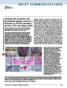
Fig. 1. The image registration problem. (a) A printed circuit board to be inspected. There are two preferred orthogonal directions (vertical and horizontal). Three fiducial patterns (black disks), marked A,B and C are imprinted on the board. The disk centers induce an affine-invariant coordinate system on the image plane. The point P may be represented uniquely as the triple (α, β, γ), where α + β + γ = 1, meaning that P = αA + βB + γC. (b) A highresolution binary image of the board when the sensor pixel orientation is not aligned with the preferred directions of the board. The positions of the fiducial centers are to be determined with subpixel accuracy. An error of ² in any of their coordinates induces an error of O(²) in the calculation of the position of P . (c) A low-resolution binary image of the board at the same orientation as (b). The accuracy in locating P decreases relative to (b).
diameter of the locale of a solid disk of radius r is Ω((log r)1/2 r−1 ) pixel units. We also provide an O(r log r) time algorithm for computing the region. This involves the investigation of the geometric structure of high order Voronoi diagrams of the unit lattice. All the information in the digital image of a solid disk is contained in the pixels on its circumference. Because of this, O’Gorman et al. 7 suggest that more precision may be obtained by adding more “circumferences” to the fiducial. This is achieved by using not a solid disk, but a “bulleye” pattern consisting of concentric rings of alternating colors. Each boundary between successive rings adds information which a registration procedure may utilize. Unfortunately, in order to achieve an order of magnitude improvement over the simple solid disk, we have to relax our requirement that the fiducial be scalable. Under this constraint, we construct a bulleye fiducial enabling image registration with O(r−2 log r) accuracy and provide an algorithm for computing its “locale”. 2. The Imaging Model To facilitate our analysis, we make a few simplifying assumptions about the imaging process. First, we consider only binary images, containing black and white pixels. Second, the sensor point-samples the scene, essentially modelling the pixels as infinitely small points. An image pixel is black if a dark point of the scene covers the corresponding sample point, otherwise it is white, as illustrated by Fig. 2. Third, the imaging procedure is noise-free, so the pixels are exactly the points of the planar lattice Z 2 . The first assumption is a worst case assumption, as real images 3
usually contain greyscales, providing additional information which may improve the registration. The second and third assumptions are best case, as real sensors are noisy. Each sensor pixel integrates over an area in the scene, and noise is inevitably present.
(a)
(c)
(b)
(d)
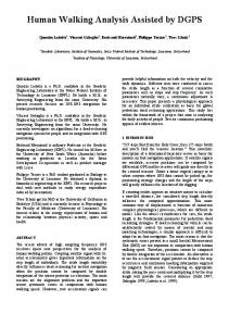
Fig. 2. Digital image of shape. (a) Original shape. (b) Point-sampling noisefree imaging model. Pixels are modelled as lattice points. (c) Digital binary pixel image. (d) Effect of doubling imaging resolution.
3. Fiducial Design Considerations Binary fiducials are black and white patterns. These patterns, when imprinted on objects to be inspected, enable precise location of select points of the pattern in their digital images. A major consideration in fiducial design is the area/accuracy tradeoff. A successful fiducial should be compact (occupy a small number of image pixels), and achieve a good registration accuracy. Bruckstein et al. 2 designed a “one-dimensional” fiducial, shown in Fig. 3, occupying a line of n pixels, and achieving a registration accuracy of 2−n pixel units. In practical terms, they are able to locate an interval of this size in which the edge of the fiducial must lie. In the same paper, they generalize this pattern to two dimensions with the same accuracy and prove that this is in a sense optimal, so no better accuracy may be achieved by a n-pixel fiducial. Their design, however, is tailored to the parameters of the image, requiring exact knowledge of the pixel size and orientation. Without this, the fiducial is useless. A more “robust” fiducial would not rely on this information. It would be essentially independent of pixel orientation (isotropic), and be “scalable” - not rely on prior knowledge of the pixel size, but gracefully trade off registration accuracy for area (e.g. resulting from an increase or decrease in sensor resolution). Here we concentrate on the design of these type of fiducials. We use solid disks as rotation and scale invariant fiducials, and bulleyes as rotation (but not scale) invariant fiducials. The bulleye fiducial significantly improves the accuracy obtainable from the simple disk. 4. The Disk Registration Problem Based on the criteria of Section 3, circular patterns, being isotropic, are good candidates to serve as fiducials. The simplest such fiducial pattern is a black disk on a white background. The center of the disk serves as the registration point. Let D(α, β, r) be a disk in the plane of radius r, centered at (α, β), and Z 2 the unit planar lattice. Call the set of lattice points σ(D) = D ∩ Z 2 the signature of D. 4
d etc... 1/2 1/4
1/8
1/16
Fig. 3. The one dimensional n-pixel fiducial of Bruckstein et al. achieving a registration error of 2−n pixel units. The pattern of black/white pixels obtained by the sensor (bottom line) is the binary expansion of 1 − d up to n digits (d is the distance from the left edge of the fiducial to the preceding lattice point). The left edge of the fiducial must therefore lie in the interval [d, d + 2−n ].
This is the noise-free point-sampled binary image of D. D is said to be consistent with σ(D). Denoting by Conv(A) the convex hull of the set A, observe that all the information of σ(D) is contained in the vertices of Conv(σ(D)) (a subset of σ(D)), in the sense that if these vertices are known, the entire signature σ may be reconstructed (by a “scan-conversion” process). The mapping of D to σ(D) is not injective. Fig. 4(a) demonstrates that distinct disks may be consistent with one signature. This means that given a disk signature, it is usually not possible to determine exactly the original disk center. However, the larger the disk radius, the more constrained the disk center is, because of the decreasing continuous curvature of its circumference. This is not true for a square-shaped fiducial, as Fig. 4(b,c) demonstrates. At some orientations, increasing the size of the square does not reduce the uncertainty in the position of its center, given its signature. As the orientation of the fiducial relative to the pixel grid is arbitrary, the worst case must be assumed. Assume the unit of distance is the image pixel size. The disk registration problem is the determination of the disk parameters with best possible accuracy from its digital signature. Denote the parameters of D by α(D), β(D) (center) and r(D) (radius) respectively. The disk registration problem can now be formulated as follows:
Disk Registration Problem: Given σ(D) - determine (α(D), β(D), r(D)).
Because of the uncertainty in the signature, there is no unique answer to the disk registration problem.
5
(a)
(b)
(c)
Fig. 4. Circular and square fiducials. (a) The solid disk fiducial. Many distinct disks may have identical signatures (the two small disks and the two large disks are consistent with the same signatures), so the disk registration problem may not be answered precisely. Constraints on disk center increase with disk radius r, so registration accuracy should improve with an increase in r. (b) Square fiducial: When the square is aligned with the pixel grid, the uncertainty in the position of its center is independent of size (0.5 pixel units), so squares are not good fiducials. (c) The square at a 45o angle orientation relative to the pixel grid. The uncertainty in this case may also reach 0.5 pixel units, independent of the size of the square.
5. Lower Bounds on Disk Registration We now address the question of how accurate a registration may be achieved using a solid disk as a fiducial pattern. The accuracy is measured in pixel units. Let σ be a disk signature, and F (σ) the locus of the centers of all disks consistent with this signature, called the feasible region of σ: F (σ) = {(x, y) ∈ IR2 : ∃r[σ(D(x, y, r)) = σ]}
.
(1)
Obviously, since any point in F (σ) is a possible center of a disk with signature σ, examination of this region will provide lower bounds on the registration accuracy inherent in the signature. These regions are the locales of Havelock (Ref. 6). a The definition (1) of F (σ) is equivalent to: F (σ) = {(x, y) ∈ IR2 : ∃r[ ∀p ∈ σ(||p − (x, y)|| ≤ r) ∧ ∀p ∈ σ c (||p − (x, y)|| ≥ r)]} where σ c = Z 2 − σ and || · || is the L2 (Euclidean) norm. This, in turn, means that F (σ) is the locus of all points in the plane closer to all lattice points in σ than to all other lattice points. These locii have been investigated in the field of computational geometry. Denote k = |σ| (the cardinality of σ). F (σ) is the cell corresponding to the point set σ in the order-k Voronoi diagram of the unit lattice Z 2 (see Lee 8 for definitions of higher order Voronoi diagrams). This is known to be a convex region of the plane (Preparata and Shamos, 9 Sect 6.3). In fact, this Voronoi diagram is a partition of the plane into convex cells, each cell a feasible region consistent with a Actually, Havelock defines a locale F (σ) for disks of a given radius r. Contrasting with F (σ), r Fr (σ) is usually not convex.
6
(a)
(b)
(c)
Fig. 5. Order-23 Voronoi cells of the lattice points Z 2 in a unit square. This structure is periodic over the entire plane. (a) L2 norm Voronoi cells. (b) L1 norm Voronoi cells. (c) L∞ norm Voronoi cells. The rich structure of the L2 norm Voronoi diagram, compared to that of the L1 and L∞ norm diagrams, is consistent with the fact that disks are better fiducials than squares.
a different disk signature of size k. In Section 6.1 we show how to compute F (σ) efficiently, given σ. Now we bound from below various geometric properties of F (σ). Note: The Voronoi cell formulation is consistent with the fact that squares are very bad fiducials. The order-k Voronoi diagram of the lattice defined using the L1 norm (corresponding to the case of an axis-aligned square) or the L∞ norm (corresponding to the case of a square at a 45o orientation relative to the pixel grid) has a very simple structure (see Fig. 5). There are very few distinct signatures of size k generated by squares, which are the unit “circles” induced by these norms, hence very few cells. Disks, which induce a L2 norm Voronoi diagram with a rich structure, are good fiducials. 5.1. Bounding the Feasible Region Diameter We now show that if a disk D(x, y, r) induces a signature σ, it is possible to translate D in the plane by a measurable amount without changing σ. Define d(D) = d(r) =
min
p∈Z 2 ,q∈∂D
max
||p − q||2
{D : r(D)=r}
d(D)
The quantity d(D) is the distance of the closest lattice point to the circumference of D, and d(r) is the worst (largest) such distance among all disks of radius r. Our first theorem guarantees the existence of disks whose circumference is distant from all lattice points. Our proof considers only disks centered at lattice points. b There may exist other disks improving this lower bound.
b After this paper was submitted for publication, we learned that Theorem 1 was proved independently by Abbott. 10
7
Theorem 1 d(r) = Ω(log(r)1/2 r−1 ) Proof. Landau 11 obtained the following number-theoretic result: The number of integers less than n which can be represented as the sum of two squares is θ(n log(n)−1/2 ). Call these the Landau numbers of n. Imagine an origin-centered √ disk D, whose circumference intersects the lattice point (r(D), 0) = (b nc, 0). Any lattice point (x, y) ∈ D represents a Landau number of n, namely x2 + y 2 , since √ x2 + y 2 ≤ b nc2 ≤ n. All lattice points representing the same Landau number lie on the same origin-centered circle. Landau’s result implies that the number of such √ distinct circles centered at the origin with radius less than r = b nc, intersecting at least one lattice point is θ(log(r)−1/2 r2 ). Hence, for large r, the number of such circles with radius between r and r + 1 is θ(log(r)−1/2 r), so the difference in radius between at least one pair of successive circles in this set is Ω(log(r)1/2 r−1 ), whence d(r) = Ω(log(r)1/2 r−1 ) 2 Theorem 2 Define F (σ) as in (1). Then diam(F ) = O(r−1/2 ) diam(F ) =
Ω(log(r)1/2 r−1 )
Proof. The upper bound follows from an extension of the proof, due to Newman, 12 that d(r) = O(r−1/2 ). The lower bound follows from Theorem 1. Indeed, for any r, there exists a Dr with radius of size O(r), which may be increased (or decreased) by order of magnitude d(Dr ) = Ω(log(r)1/2 r−1 ) without changing its signature. The concentric disk between the circumference of Dr and the nearest lattice point of radius r ± d(Dr )/2 may be translated (i.e. its center moved) in any direction the distance d(Dr )/2. The theorem follows. 2 5.2. Bounding the Feasible Region Area In this section we bound the area of the feasible region F (σ). Theorem 3 Area(F ) = Ω(r−2 )
.
Proof. It is known 8 that the number of cells in an order-k Voronoi diagram of n points is O(nk). For any integer m, and n = m2 , consider the portion of the unit planar lattice Z 2 ∩ [0, m]2 . The order-k Voronoi diagram of this θ(n) point set behaves periodically over this truncated lattice (except at the boundaries), so its global structure is determined uniquely by its local structure in the unit square [0, 1]2 . There are O(nk) cells in the entire structure, consisting of n unit squares, so there are O(k) cells in one unit square. As the unit square has unit area, there must
8
be at least one cell with area Ω(1/k). The signature of a disk of radius r contains k = θ(r2 ) lattice points, c implying the theorem. 2 Note that Theorem 3 implies the lower bound diam(F ) = Ω(r−1 ), which is weaker than the bound obtained in Theorem 2. 6. Disk Registration Algorithms This section is dedicated to the presentation and analysis of efficient disk registration algorithms. We distinguish between exact algorithms - those which take the signature σ as input, and supply the vertices of F (σ) as output, and approximate algorithms - those which take the same signature σ as input and supply a single point, an approximation of the disk center, as output. In the former case, some point of F (σ) has to be chosen as the registration point (usually some sort of center), but knowledge of the entire region may be useful. 6.1. Exact Algorithms Notation: Let L be a subset of the lattice points Z 2 , and B the set of lattice points which are the vertices of lattice cells having vertices both in L and in Lc . Denote the inner boundary of L by ∂I L = B ∩ L and the outer boundary of L by ∂O L = B ∩ Lc . The boundary of L is ∂L = B. We now show how to compute the feasible area F (σ) in O(r log r) time, where r = r(D) is the radius of a disk D consistent with σ. d An algorithm for computing F (σ) with this complexity has been proposed by Bhattacharya 13 in a different context, but is more complicated. When analyzing the time complexity of an algorithm, we must first define the computation model. In our case, it is critical to specify how we receive the binary image data: After all, there is not much point developing a fast algorithm when just loading all the data into memory may dominate the run time. We adopt the (reasonable) assumption that the binary image is already present in memory, and we can, in O(1) time, access any pixel value. The following lemma formalizes what we have already mentioned, namely, that all information in the signature is conveyed by its boundary pixels. Lemma 1 When computing F (σ), it suffices to consider only ∂σ. Proof. For any fixed r, the locus of centers of disks of radii r consistent with σ is given by à ! à !c \ \ [ Fr (σ) = D(p, r) D(p, r) p∈σ c
p∈σ
It is easy to see that ∩p∈σ D(p, r) = ∩p∈∂I σ D(p, r), since the disk of radius r centered at p is just the locus of centers of all disks of radius r containing p, and a disk of radius r contains σ if and only if it contains ∂I σ. If p ∈ σ c − ∂O σ, then for c The
exact number of points is πr2 + o(r2 ), as Theorem 7 states. that it is not important, in terms of asymptotic analysis, which consistent disk is taken, as the radii are all of the same order of magnitude. d Notice
9
any r ≥ 12 , D(p, r) contributes nothing to [∪p∈σc D(p, r)]c . Since F (σ) = ∪r>0 Fr (σ), when σ is fixed only ∂σ is important in the calculation of F (σ) too. 2 Given any point of ∂σ, we can trace along the boundary of the disk signature to find all other points of ∂σ. In our computation model, we assume that at least one point of σ is known in advance. It is then possible to find a point of ∂σ from this by advancing in any fixed direction. Since there are obviously O(r) points in ∂I σ and ∂O σ, there are also O(r) points in ∂σ. Following the methods in Preparata and Shamos, 9 Chap. 7, the collection of all disks consistent with σ may be represented by the set Q0 (σ) ⊆ IR3 (parameter space), where (x, y, r2 ) ∈ Q0 (σ) if and only if ∀(xi , yi ) ∈ σ
(x − xi )2 + (y − yi )2 ≤ r2
and ∀(xi , yi ) ∈ σ c
(x − xi )2 + (y − yi )2 > r2 .
It is obvious that F (σ) is the projection of Q0 (σ) on the XY plane. Consider the ~ : IR3 → IR3 given by bijective mapping U ~ ( (x, y, z) ) = (x, y, z − x2 − y 2 ) U By Lemma 1, it suffices to consider only ∂σ, so the point (x, y) is the center of a disk of radius r consistent with σ if and only if ~ ( (x, y, r2 ) ) ≥ ki ∀(xi , yi ) ∈ ∂I σ ~ai · U ~ ( (x, y, r2 ) ) ≤ ki ∀(xi , yi ) ∈ ∂O σ ~ai · U where ki = x2i + yi2
~ai = (2xi , 2yi , 1)
~ (Q0 ). It follows that Q is the convex polyhedron obtained as the interLet Q := U section of the appropriate half-spaces defined by the set of planes {~x ∈ IR3 | ~x · ~ai = ki } corresponding to the lattice points {(xi , yi ) ∈ ∂σ}. Obviously, Q and Q0 have the same projection on the XY plane, which is just F (σ). The polyhedron Q can be computed, for instance, using Muller and Preparata’s O(n log n) time algorithm for computing the convex polyhedron defined by n hyperplanes (described in Preparata and Shamos, 9 Chap. 7). As here n = O(r), Q(σ) is computable in O(r log r) time. Computing F from Q is trivial, so Theorem 4 Given σ, F (σ) may be computed in O(r log r) time. If we would like just one consistent disk, it is possible to find the parameters of the disk of minimal radius consistent with σ in O(r) time by simple linear programming, using e.g. the algorithms of Megiddo 14 or Matouˇsek et al. 15 The above analysis enables us to prove:
10
Theorem 5 Given a signature σ, the locus of radii of the disks consistent with σ is an interval (in IR). Proof. The polyhedron Q(σ) is convex, therefore its projection on the Z axis ~ is continuous, so the projection of Q0 (σ) on the Z is an interval. The mapping U 2 2 axis is also an interval [r1 , r2 ]. Hence, the locus of the radii of the disks consistent with σ coincide with the interval [r1 , r2 ]. 2 6.2. Combinatorial Geometric Bounds Denote by Comp(P ) (the complexity of P ) the number of edges of a planar polygon P . Our previous results enable us to obtain an upper bound on the complexity of the cells of the order-k Voronoi diagram of the planar lattice Z 2 . This contrasts with the case of arbitrary planar point sets, where no non-trivial bound exists. As stated above, the polyhedron Q has O(r) faces, and F , which is Q’s projection, is a cell in an order-θ(πr2 ) Voronoi diagram. Conversly, any cell in any t-order Voronoi diagram is a feasible area for a disk signature of size t. Putting this together with Theorems 2 and 3 yields: Theorem 6 Let C be a cell of an order-k Voronoi diagram of the lattice Z 2 . Then Comp(C) =
O(k 1/2 )
Diam(C) =
O(k −1/4 )
Diam(C) =
Ω(k −1/2 (log k)1/2 )
Area(C) =
Ω(k −1 )
6.3. Recognizing Digital Disks Nakamura and Aizawa 16 present an algorithm to determine whether a given set of lattice points are the digital signature of a disk. Section 6.1 implies a simpler algorithm achieving the same goal. A given set of lattice points L is the digital signature of a disk iff F (L) 6= ∅. As we have shown, given any point of L, F (L) may be computed in O(n log n) time, where n is the size of ∂L. 6.4. Approximate Algorithms In Section 6.1, we showed how to compute F (σ) efficiently. The algorithm is, however, fairly complex, and for many applications, the entire region is not of interest. Usually just one point is required as an “estimate” for the fiducial center, along with an estimate of the radius. Algorithm Register is a simple (and essentially trivial) algorithm for estimating the radius and center of a disk given its signature:
11
Fig. 6. Voronoi cells (feasible regions) F (σ) and centroids C(σ) associated with digital signatures of disks containing 13 lattice points. Note the variance between the sizes of the cells and the fact that not always C(σ) ∈ F (σ) (C is not always consistent with F ).
Register(Signature σ) begin p rest := |σ|/π ; (α, β)est := centroid(σ) ; end ; The cardinality of σ(D) may be calculated efficiently from the lattice points on ∂I σ using Pick’s theorem (Coxeter, 17 p. 208). Algorithm Register is straightforward enough. The natural question is whether the estimates it produces are consistent, i.e. whether (α, β)est ∈ F (σ), and rest is a possible radius of a disk consistent with σ. The answer to this is negative. Fig. 6 shows a centroid of a disk signature which lies outside the feasible region of the same signature. This already indicates that the algorithm is approximate. However, the next few theorems show that, although the Register algorithm does not always produce consistent estimates, it does perform well on the average. First some notation: Notation: ∆(D) ∆(r)
= |σ(D)| − πr(D)2 =
max
{D:r(D)=r}
∆(D)
The quantity ∆(D) is the discrepancy of the disk D - the difference between its area and the number of lattice points in its interior. The quantity ∆(r) is the worst (largest) discrepancy among all disks of radius r. The following theorem summarizes some known bounds on ∆(r). 12
Theorem 7
1. (Iwaniec and Mozzochi
18
) ∆(r) = O(r7/11 ).
2. (Hardy 19 ) ∆(r) = Ω(r1/2 (log r)1/4 ). Kulpa 20 reports the results of simulations aimed at estimating ∆(r). He was apparently unaware of the wealth of analytical results bounding this quantity (see Kr˝ atzel, 21 Chap. 3 for a historical survey), of which those quoted in Theorem 7 are, to the best of our knowledge, the best to date. Kendall proved an average case result: Theorem 8 (Kendall 22 ) E{D:r(D)=r} [∆(D)] = O(r1/2 )
(2)
where (α(D), β(D)) is uniformly distributed in [0, 1]2 . Kendall’s result is a consequence of an estimate of the zero order moment of the distance of the points of σ(D) from the center of D. The following lemma generalizes this to higher-order moments: Lemma 2 Let D be a disk with center (α, β) and radius r. Define, for any nonnegative integer k, the complex random variable X Rk (α, β) = [p − (α + iβ)]k p∈σ(D)
where i =
√
−1 and p is a lattice point interpreted as a complex number. Then ½ πr2 k = 0 E[Rk ] = 0 k>0 E|Rk − E[Rk ]| =
O(rk+1/2 ) .
where (α, β) is uniformly distributed in [0, 1]2 . Proof. See Appendix A. 2 The special case k = 0 of Lemma 2 is Kendall’s result. We shall need the k = 1 case in the sequel. The bounds summarized in Theorem 7 may be used to quantify the accuracy of the estimate of the disk radius by Algorithm Register. The closer |σ(D)| is to the true area of the disk D, namely, πD(r)2 , the more accurate the estimate rest will be. Theorem 7 (1) implies that the estimate always satisfies (in the worst case) |r − rest | = O(r−4/11 ) and by (2), on the average (over all disk centers consistent with σ) E|r − rest | = O(r−1/2 ) . The accuracy of the centroid estimate of Algorithm Register for the disk center may be bounded too. Note that the centroid is determined by the signature only, so just as a signature σ defines a unique feasible region, it determines also a unique centroid. Analogously to the analysis of Theorem 3, the number of centroids 13
corresponding to signatures of size k is O(k) per unit square. Fig. 6 shows some of these. Using the terminology of Lemma 2, the average distance between a disk center (α, β) consistent with σ and the centroid of σ is E||(α, β) − (α, β)est || =
E|R1 | θ(πr2 )
.
Since, by Lemma 2 E|R1 | = O(r3/2 ) , we have E||(α, β) − (α, β)est || = O(r−1/2 ) .
(3)
Our results mean that the improvement in average registration accuracy caused by an increase in disk radius behaves asymptotically like r−1/2 . This confirms and explains the empirical results of Bose and Amir. 4 7. The “Bulleye” Fiducial O’Gorman et al. 7 mention that a more promising variant of the circular solid disk fiducial might be the “bulleye” - a number of concentric rings of alternating colors. They show, under the (plausible but mathematically incorrect) assumption that the signatures of concentric rings are “uncorrelated”, that the average registration accuracy of O(r) concentric rings (where the width of each ring is a constant number of pixels) using a weighted centroid algorithm, is O(r−1 ). Were it true, this would mean that an order of magnitude improvement in registration accuracy (relative to (3)) would be achievable without sacrificing any additional space beyond that of the simple disk. In this section, we design a bulleye fiducial of radius O(r) achieving registration accuracy O(r−2 log r). This increase in accuracy relative to the simple solid disk is due to the fact that we assume prior knowledge of the pixel size. We do not require, however, knowledge of the pixel orientation. The bulleye is a circular version of a variant of the optimal one-dimensional fiducial of Bruckstein et al. (see Fig. 3). We prove that these fiducial patterns have a feasible area of log r diameter ≤ r(r+log r) , and show how to achieve this accuracy. The variant of the optimal one dimensional fiducial we use is robust to limited noise in the image. 7.1. A Robust One Dimensional Fiducial Definition 1 A δ-noisy one dimensional lattice is an infinite set of points {pi ∈ IR : i ∈ Z}, such that ∀i |pi − i| ≤ δ. Let us see where the algorithm, described in Fig. 3, for the optimal one dimensional fiducial can fail as a result of image noise. Consider, for example, the first component of the fiducial, consisting of two blocks of size 12 , one white and one black. The algorithm may err only if a lattice point was close to the boundary between the blocks, and “moved” from one to the other as a result of noise. Assuming the noise is bounded by δ (a δ-noisy lattice), all we have to do to correct this is check whether the lattice point is in the interval [ 12 − 2δ, 21 + 2δ]. This can be 14
achieved by appending a unit length window to the fiducial which is all white except for that interval, which is black. The position of this “error-correction” window in the fiducial has no importance, as long as its distance to the edge of the two-halves block is a integral number of pixels. We can correct noise in all other components of the fiducial by appending to them similar error-correction windows (see Fig. 7). Since it is impossible to achieve registration accuracy better than δ on a δ-noisy lattice, the length of the entire fiducial should be n pixels, where 2−n ≈ δ. log r For δ = r(r+log r) , the length of the optimal one-dimensional fiducial achieving registration accuracy of δ (including error-correction windows) is 2 × log2 δ −1 ≤ 2 log2 r.
(a)
(b)
Fig. 7. Robust one-dimensional fiducial construction. (a) Four-quarters block of the optimal one-dimensional fiducial of Fig. 3. (b) The error-correction window corresponding to the block of (a). In general, it is all white, except for a strip of width 2δ at each interval boundary in (a) not covered in the windows corresponding to the previous blocks.
7.2. The Two Dimensional Bulleye log r This circular fiducial is very simple. For δ = r(r+log r) , let b1 , w1 , b2 , w2 , . . . , bm , wm be the lengths of the black and white strips (respectively) of the onedimensional fiducial built for a noisy δ-noisy lattice (as described in Section 7.1). The two dimensional fiducial is constructed from a solid black disk of radius r, a white ring of width 2, and a sequence of black and white rings, where the i’th black (white resp.) ring has width bi (wi resp.) (see Fig. 8). The radius of the resulting fiducial is ≤ r + 2 log2 r = O(r).
Fig. 8. To create the bulleye fiducial achieving a registration accuracy of δ = log r , rotate the δ-robust one-dimensional fiducial around a solid black r(r+log r) disk of radius r enclosed by a white ring of width 2.
7.3. Bounding the Center of the Bulleye It is possible to compute the center of this fiducial from its digital image with accuracy δ. First locate the center to within one pixel accuracy. This is possible 15
because of the white ring of two pixels radius between the solid black disk and the rotated one-dimensional fiducial. Using the algorithms described earlier in the paper (e.g. the centroid algorithm) on the signature of the solid disk (which may be isolated), the center may certainly be found up to one pixel accuracy. To find the center of the bulleye with accuracy δ, we use two lines of image pixels only - the horizontal row not above and closest to the center of the bulleye, and the vertical column not to the right and closest to the center of the bulleye. These horizontal and vertical lines are adjacent to the pixel just found. Call these lines the X-line and Y -line, respectively. Assume that the true fiducial center is δx pixel units above the X-line, and δy pixel units to the right of the Y -line. The log r square of size δ = r(r+log r) centered at (δx , δy ) contains the center of the bulleye. We now show how to compute (δx , δy ). The pixels along the X-line form the image of a one-dimensional fiducial which has shifted to the left by sx pixel units, in which the individual blocks have shifted relative to each other by no more than δx2 δx2 − r r + log r
≤ = =
1 1 − r r + log r log r r(r + log r) δ
pixels. Since this ”noise” is not more than δ, the δ-robust one-dimensional fiducial algorithm covers this case. Apply the “error-correction” algorithm on this pixel pattern to obtain the estimate dx . Do the same for the pixels on the vertical Y-line to obtain dy . The quantity sy is defined analogously to sx . By elementary geometry, r2 = (r − sx )2 + δx2
r2 = (r − sy )2 + δy2
yielding sx = r −
p
r2 − δx2
sy = r −
q r2 − δy2
.
As δx = sx + dx and δy = sy + dy , this results in the quadratic equations for the two unknowns δx and δy : p δx = dx + r − r2 − δx2 q δy = dy + r − r2 − δy2 which may be solved easily. 8. Concluding Remarks We have presented analytic bounds on the registration accuracy achievable in binary images using circular fiducials, along with efficient methods for performing the registration. For solid disks, Ω((log r)1/2 r−1 ) is the best that can be hoped for, 16
the simple centroid algorithm achieving O(r−1/2 ) accuracy on the average. Whether the lower bound may be achieved depends on improving the upper bound on the diameter of the feasible regions. The non-scalable bulleye fiducial improves the registration accuracy of a solid disk by an order of magnitude to O(r−2 log r). It is not clear whether a similar order of magnitude improvement may be achieved for a scalable version (e.g. containing a constant number of rings). This will be resolved when the relation between the lattice points on the convex hulls of concentric ring signatures is determined. They seem to be “uncorrelated” in a sense, but this must be quantified more precisely. A major open problem is whether an exponentially small registration accuracy may be achieved using some isotropic scalable fiducial pattern. The circular fiducials investigated here seem to be able to yield only a polynomially small registration accuracy. Our analysis deals with the perfect model where the signature is not noisy. In real-world scenarios, it is usually impossible to eliminate noise from the imaging process. It would be interesting to determine how robust our methods are with respect to noise. Empirical results of O’Gorman et al. 7 indicate that circular fiducials are indeed robust. Our methods could probably be improved if our assumption of a binary image were relaxed. Greyscale images contain more information than binary images, and are readily available. This case deserves separate investigation. Acknowledgements Thanks to Alfred Bruckstein for presenting these problems to us and to Ronny Roth for interesting discussions on number theory. Thanks also to Avigail Orni for many helpful remarks. References 1. C. Gotsman. On the most robust affine basis. Pattern Recognition Letters, 14:647– 650, 1993. 2. A.M. Bruckstein, L. O’Gorman, and A. Orlitsky. Design of shapes for precise image registration. Technical report, AT&T Bell Labs., 1989. 3. I. Amir. Algorithm for finding the center of circular fiducials. Computer Vision, Graphics and Image Processing, 49:398–406, 1990. 4. C.B. Bose and I. Amir. Design of fiducials for accurate registration using machine vision. IEEE Transactions on Pattern Analysis and Machine Intelligence, 12:1196– 1200, 1990. 5. J.W. Hill. Dimensional measurements from quantized images. In D. Nitzan et al., editor, Machine Intelligence Research Applied to Industrial Automation, pages 75– 105. SRI, 1980. 6. D.I. Havelock. The topology of locales and its effects on position uncertainty. IEEE Transactions on Pattern Analysis and Machine Intelligence, 13(4):380–386, 1991. 7. L O’Gorman, A.M. Bruckstein, C.B. Bose, and I. Amir. Subpixel registration using a concentric ring fiducial. In Proceedings of Int. Conf. on Pattern Recognition. IEEE, 1990.
17
8. D.T. Lee. On k-nearest neighbor Voronoi diagrams in the plane. IEEE Transactions on Computers, 31(6):478–487, 1982. 9. F.P. Preparata and I.M. Shamos. Springer-Verlag, New York, 1985.
Computational Geometry: An Introduction.
10. H.L. Abbott. Approximation for the location of the center of a disk. SIAM Review, 34:658–661, 1992. 11. E. Landau. Uber die einteilung der ... zahlen in 4 klassen .. Arch. Math. Phys., 3(13):305–312, 1908. 12. D.J. Newman. A gradually turning curve must come near a lattice point. Journal of Number Theory, 6:7–10, 1974. 13. B.K. Bhattacharya. Circular separability of planar point sets. In G.T. Toussaint, editor, Computational Morphology, pages 25–39. Elsevier-Science, 1988. 14. N. Megiddo. Linear programming in linear time when the dimension is fixed. Journal of the ACM, 31:114–127, 1984. 15. J. Matouˇsek, M. Sharir, and E. Welzl. A subexponential bound for linear programming. In Proceedings of the 8th Annual ACM Symposium on Computational Geometry, pages 1–8, 1992. 16. A. Nakamura and K. Aizawa. Digital circles. Computer Vision, Graphics and Image Processing, 26:242–255, 1984. 17. H.S.M. Coxeter. Introduction to Geometry (2nd Edition). Wiley and Sons Inc., New-York, 1980. 18. H. Iwaniec and J. Mozzochi. On the divisor and circle problems. Journal of Number Theory, 29:60–93, 1988. 19. G.H. Hardy. On Dirichlet’s divisor problem. Proceedings of the London Mathematical Society, 2(15):1–25, 1916. 20. Z. Kulpa. On the properties of discrete circles, rings and disks. Computer Vision, Graphics and Image Processing, 10:348–365, 1979. 21. E. Kr˝ atzel. Lattice Points. Kluwer Publishers, 1988. 22. D.G. Kendall. On the number of lattice points inside a random oval. The Quarterly Journal of Math. Ser. B (Oxford), 19:1–25, 1948. 23. M. Abramowitz and I. Stegun. Handbook of Mathematical Functions. Dover Publications Inc., New-York, 1970.
Appendix A Lemma 2 Let D be a planar disk with center (α, β) and radius r. Define in the complex plane, for any non-negative integer k, the complex random variable X Rk (α, β) = [p − (α + iβ)]k p∈σ(D)
where i =
√
−1 and p is a lattice point interpreted as a complex number. Then ½ πr2 k = 0 E[Rk ] = 0 k>0 E|Rk − E[Rk ]| =
O(rk+1/2 ) .
where (α, β) is uniformly distributed in [0, 1]2 . 18
Proof. The complex random variable Rk is doubly periodic in α and β and hence can be expanded, at least formally, as a Fourier series. X Rk (α, β) = an,m e2πi(nα+mβ) n,m
Define the function Ur : C −→ C as ½ Ur (z) = Then
X
Rk (α, β) =
zk 0
if |z| ≤ r otherwise
Ur ((j − α) + i(k − β)),
j,k
where (j, k) range over all lattice points. Now, by an inverse Fourier transform, Z 1Z 1 an,m = Rk (α, β)e−2πi(nα+mβ) dαdβ 0
=
XZ j,k
0
Z
j
j−1
k
Ur (u + iv)e−2πi(nu+mv) dudv
k−1
By transforming to polar coordinates, denoting γ = (m2 + n2 )1/2 and α = arg(n + im): Z 2π Z r an,m = xk eik(θ−α) e−2πiγx cos θ xdxdθ 0 0 ·Z 2π ¸ Z r = e−ikα xk+1 e−2πiγx cos θ eikθ dθ dx 0
0
For γ = 0 (n = m = 0), direct computation yields ½ πr2 k = 0 a0,0 = E[Rk ] = 0 k>0 For γ > 0
Z
r
k −ikα
an,m = 2πi e
xk+1 Jk (2πγx)dx
0
where Jk (z) is the k’th order Bessel function. Using the integral identity for any non-negative integer k (Abramowitz and Stegun, 23 Eq. 11.3.20) Z s xk+1 Jk (x)dx = sk+1 Jk+1 (s) 0
we obtain an,m =
ik e−iα rk+1 Jk+1 (2πγr) γ
It is well known (Abramowitz and Stegun,
23
Eq. 9.2.1) that for all k ≥ 0,
Jk (z) = O(z −1/2 ) 19
(n, m) 6= (0, 0)
whence |an,m | = (n2 + m2 )−3/4 O(rk+1/2 )
(n, m) 6= (0, 0) .
Parseval’s identity from Fourier analysis yields: Z 1Z 1 2 E|Rk | = |Rk |2 dαdβ 0 0 X = |an,m |2 n,m
Consequently E|Rk − E[Rk ]|2
= E|Rk |2 − |E[Rk ]|2 X |an,m |2 = (n,m)6=(0,0)
= O(r2k+1 )
X
(n2 + m2 )−3/2
n,m
Let s(l) be the number of representations of the integer l as the sum of two squares. It is well known that s(l) = O(lδ ) P∞ for every δ > 0, so l=1 l−3/2 s(l) is convergent, and 2
E|Rk − E[Rk ]|
2k+1
=
O(r
)
=
O(r2k+1 )
∞ X
l−3/2 s(l)
l=1
It follows that E|Rk − E[Rk ]|
≤
p E|Rk − E[Rk ]|2
=
O(rk+1/2 ) ,
as required.
2
20