Support for Software Federations: the PIE1 Platform G. Cugola1, P.Y. Cunin2, S. Dami2, J. Estublier2, A. Fuggetta1, F. Pacull3, M. Rivière3, H. Verjus2,4 1 Politecnico di Milano, Italy.
[email protected],
[email protected] 2 LSR laboratory, Grenoble University, France. {Pierre-Yves.Cunin, Samir.Dami, Jacky.Estublier}@imag.fr 3 Xerox Research Centre Europe, Grenoble France. {Francois.Pacull, Michel.Riviere}@xrce.xerox.com 4
LLP/CESALP laboratory, Savoie University, Annecy France.
[email protected]
1
Introduction
Research about software processes modelling and support, even during the last decade, has suffered from a lack of practical credibility. Most of the solutions proposed have not gained wide acceptance by the software industry and, moreover, some fundamental issues like evolution have not yet found any reasonable solution. For these reasons, it was a clear decision in the PIE project to build a platform providing the requisite features for evolution support, and also addressing many of the aspects that have so far impeded wide acceptance of process support. Therefore, a major objective of the PIE platform is to facilitate the implementation, in a company, of a complete process support system. This includes the tools, systems and techniques that process participants (developers, managers) are familiar with, as well as PIE specific components. The tools that process participants are used to are likely to be Commercial Off The Shelf (COTS). The motivation to build such a Process Support System (PSS) endeavors to interoperate a number of components, including COTS systems, such that they collectively perform an expected service. We call this set of components a federation. We define a federation as an application built mainly from COTS tools, which implies that they are (mainly) autonomous, and they are not modifiable. The Apel2 foundation is a federation manager, specialized in process support. The goal of the PIE federation (as well as most federations) is not only to provide collectively a (complex) service, but also to preserve the independence and autonomy of its components, to be open to dynamic change in composition and distribution
1
PIE: Process Instance Evolution. Esprit Project 34840. UJF Grenoble, Victoria U. Manchester, Dortmund U., Savoie U., Politecnico di Milano, Xerox Grenoble, Teamware, Dassault Systèmes. 2 Apel is the process support system from which the PIE platform is built.
(new/changed/ removed/moved components), as well as in changes and enhancements of the behaviour and characteristics of the whole federation. Until now, most work addressing interoperability within a federation has focussed on basic interactions between distributed components. We believe that federations must rise above this level; we need new concepts for federation interoperability and new approaches for the definition, control and evolution of software federations. In section 2, we will explore the concept of federation and the interoperability paradigms that can be used. In section 3, we show how these paradigms can be defined and controlled. Section 4 presents the PIE Middleware to which a large part of federation control has been delegated. Conclusions are reported in section 5.
2
Federations paradigms
Today, many COTS tools are available like workflow tools, GroupWare tools, configuration management tools, change management tools, document management tools, but also more general ones like text editors, spreadsheets, databases and web browsers, etc. Building a distributed software application [10] often consists of building a federation where most components are COTS and only a few are application specific. Such components are autonomous and manage their own resources or internal processes. It is interesting to note that the design and architecture of software systems is evolving under the pressure of a number of factors:
• Distribution requires components to communicate through explicit means, • Maintainability requires minimal change to the source code of components, • Evolutivity and mobility require that components are kept independent and autonomous. • Cost requires buying instead of building. The number of COTS tools is rapidly increasing, their functionality is more comprehensive and their price is dropping. Software products are evolving from being monolithic and proprietary toward federations. It is of strategic importance to find a practical way to build federations. Different strategies [13] can be used to define a federation out of a number of COTS. 2.1
Control-based paradigm. The “dictatorship”.
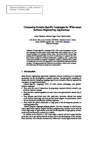
The basic idea is to abstract (i.e. encapsulate) the services provided by each component in order to hide their heterogeneity (formalism, platform etc.). The services (API) have to be (re)defined in a common formalism (IDL), in such a way that one tool can call another, whatever their respective internal formalisms and communication technology. This is a Corba-like philosophy. To program a federation, a modeller will have to write a specific piece of code, the supervisor, which calls the right components at the right time with the right parameters. This approach is the usual way to build an application from software components. Components have local models and local states inaccessible from the
outside. They provide and call services and have neither independence nor autonomy (see Fig. 1). However, each component may still interact on their own with users or other federations, so they keep some independence and autonomy outside the Main Component
Supervisor
Component 2
Component 3
Communication Local Models COTS
Component 1
Local states
Fig. 1. The dictatorship paradigm federation. Let us use a metaphor with a human society to illustrate process federation architectures. Each society agent (COTS) is a human or a business with its own model and goal, and it is capable of providing some services in an autonomous way. The control-based paradigm belongs to a fully centralized society. The goal and the rules of the society are clearly defined and enforced by a centralized government (the supervisor). The place and role of each human/company is defined and controlled by the government. This is a dictatorial society in which agents are supposed neither to know to which goal they should contribute, nor to take any initiative to contribute to change the state of the society. This may be found to be undesirable for a human society, but is perfectly acceptable for a software federation.
2.2
The Common Universe approach.
COTS tools are usually large and designed to fit a number of client’s needs without it being possible for clients to change or to extend the source code. For that reason most COTS provide clients not only with an API, but also with a specific formalism, usually different from the source code language, designed to easily adapt the COTS tool behavior to each client’s specific use. For example, a database provides schemas, spreadsheets provide computation sheets, planners provide planning modellers, PSSs provide process modellers and so on. We call the “program” written in this formalism the behaviour model of the component3. See Fig 2. COTS tools, being designed to be autonomous, directly interact with the external world (users and/or common computer resources like network, database, operating system or file system). These features and devices being common to all COTS tools, we call them the Common Universe (CU). The fact that a component has direct interaction with the common universe has profound consequences on its design: it has to behave in an unpredictable context. COTS designers usually try to identify a 3
Usually, it is not possible to adapt the behavior of not COTS components. In this case, the component source code is its own behaviour model (but at a lower abstraction level).
number of “abnormal” behaviours, and to identify convenient responses to them, in a fixed or customizable (i.e. programmable) way. This kind of behaviour can be said to be the Common Universe model of the tool4. Each COTS contains: • Behaviour model. Description of what the component does (its specific customization). • Interface. External description of the services that the component provides (API). • Common Universe model. Description of component action/reaction to CU evolution. • Current state (persistent or not). For software applications, the common universe always contains the computer itself (files, network, modems, processors, databases, screens, etc.). However, applications can include (and potentially share) many other real world knowledge (users, mechanical artifacts, activities, etc.) or they can share abstractions (language concepts like variables, “objects” and so on). All this, when reified, constitutes the common universe. If different components in the federation have a similar application domain, it is likely that their local states contain the same knowledge. However, it is unlikely to be represented in the same way, or to be modeled using the same concepts. This is particularly true in process federations where each component deals with different facets of the same process. For example, the fact "activity FixBug is under way", is known by different components and interpreted in different ways: the SCM tool builds a workspace for the activity, the workflow tool adds an activity in an agenda, the planner starts the tasks and allocates resources, and so on. Further, a tool can use the concept of task, another one of activity, a third one of workspace, and their knowledge overlaps but is not identical; their have only partial views; none has a complete knowledge. Still this knowledge is part of the CU. Many aspects of the CU model appear as atomic from the federation point of view but involve different components. For example, creating an activity in the CU, (which is an atomic operation) may involve MSProject (for planning), Lotus Notes (for notification), Adele (for workspace creation) and a monitoring tool (for the team leader control board). There is a need to coordinate, in a fine-grained way, the actions of all the components. The CU provides a sound basis on which the federation components can synchronize their work, because they can all observe the CU, and update their local state accordingly, or change the CU according to changes performed in their local state during execution. In the above example, the creation of a common activity changes the CU; this is noted by the components, each one reacting in its own way: updating planning (MSProject), creating a workspace (Adele) and so on. The CU approach, consisting in bringing as much as possible into a single common formalism and data repository, borrows similarities from database federations, but 4
For standard software components, the CU model is missing; for usual COTS, it is simple. PSSs are unique in that their “raison d’être” is to deal with CU changes; the PSS behaviour model is its CU model.
there are at least two major differences. In a database federation, the goal is to find a common schema from which the data stored in the different databases can be accessed. In our approach, the local store of components is never accessed through the common model. The goal of the common universe model is to define the behavior of the federation as a whole, whether or not this overlaps with the component process and/or persistent data. In case of overlap, it is up to each component to make its local data consistent. It is up to the component to decide what consistent means. The other major difference is that the purpose is not the static definition, but the dynamic behavior, i.e. the process. Really there is not much similarity between these two approaches.
2.3
The simple CU approach. The “anarchy”
The simple implementation of such an approach is presented by the ProcessWall [3]. There is no CU model; the architecture is based only on the effective presence of the CU, on which each component synchronizes its activity during execution (see Fig. 2). Foundation
C om m on U niverse
C om m unication
Com p.1 ponent 1
Com p.2
Local C U M odels
C om p3
Local states
Fig. 2. The anarchy paradigm In our society metaphor, the CU-based paradigm corresponds to an ultra-liberal society, where each human/organization observes the state of the society (CU) and decides to “collaborate” freely to its evolution. Groups of humans can handle work in common by observing the actions of the others (cooperation between overlapping PSSs). No federation process (the goal i.e. the desired future) is defined, no rules (correct behaviours and laws) are enforced. It is an anarchic society; which can work only if each component (human) behaves “correctly”, which is unlikely in a human society, but not in a computer federation.
2.4
The controlled CU approach. From “dictatorship” to “anarchy”.
In the control-based approach 2.1, components do not know in what they are participating, but there is formal knowledge of exactly what will be executed and how (it is the supervisor’s source code). In the simple CU approach 2.3, each component knows to what it contributes, but there is no plan for future actions. The first approach provides the goal and control desirable in a federation, but introduces severe limitations (partitioning) and lack of flexibility. The simple CU approach provides the desirable flexibility and generality, but at the cost of losing global control (goal and rule enforcement). There are, however, intermediate positions between dictatorship and anarchy. If a CU is shared by components, its behaviour is an abstraction of the "composition" of all components’ CU behaviours. If the federation CU model is formally defined and executed, it avoids anarchy, and it allows modellers and managers to understand, customize, and optimize the federation process. The federation CU model expresses (part of) the federation goal. If this federation CU model is executable (and executed) and if each one of the federation’s components is able to execute its part, the goal of the federation becomes explicit and enforceable. It is semantic interoperability [2][1]. The CU model contains the functional aspects of the CU behavior (the what), not the operational ones (the how). We also define an operational model, whose purpose is to focus on defining how aspects mentioned in the CU model should or must be handled. Instead of relying on implicit and asynchronous invocation, this model prescribes the reaction to CU changes, and explicitly indicates the consistency required for a given reaction. The operational model contains information related with the consistency control of the CU model implementation much as the ordering of component invocations for the same CU change, transaction control and so on. To do so, the interpreter of that model has to know of the federation components and their services, and has the capability to explicitly invoke these services. It relies on an explicit and synchronous invocation paradigm. See figure 3. In our metaphor, the society has a global society development plan (CU model) and has a government (the interpreters of the CU and operational models). If using only the CU model, the government executes the plan, which means it simply asks the society to do the work (e.g. build a highway). Agents, collectively, are supposed to be aware of what has to be done and to do it as they like. This society has both a goal (CU model) and a government, even if the latter has very little power and initiative. It is unlikely to work in human society. If using the operational model, the government not only can ask for something to be done but can also decides who will do it and how it will be done (the operational model interpreter directly calls the components that can do the job). The government can thus decide which aspects of the development plan are to be under complete control (like the army), or partially controlled (like health services), or completely free (most normal trade). This society can cover the complete spectrum from dictatorial (the operational model controls everything; it is the supervisor), to anarchy (neither operational model nor CU model).
3
PIE architecture
The PIE architecture implements the last federation paradigm (2.4). The foundation has to provide a repository for the CU, a CU model (and its interpreter) and an operational model (and its interpreter). The operational model interpreter relies on a dedicated middleware responsible for providing basic communication facilities (messages and method calls), but also to provide specific control services. The components of the federation (see Fig. 3) are of two kinds:
• Components which provide the functionalities of the PIE system. These
•
components are the standard ones developed within the project: pro-active monitoring support, change and decision support [14] and evolution strategy support [15]. Components which are COTS tools or proprietary components specific to an application and fulfilling the application users requirements.
In PIE, it is the operational manager who is in charge of translating the operational model into a number of rules and laws applied to the communications (thick double arrow). The PIE Middleware will be in charge of supporting and interpreting these rules, and realizing the communication. The PIE Middleware is different from usual middlewares (such as CORBA [4], [5] or Java Message Service [7], etc.) in that existing middlewares provide a communication mechanism but do not ensure or enforce any system property. We consider that federation control requires the close control of a number of communication properties like roles played by components in the federation context, rights and duties associated to these roles, substitution of components, mobility of components and so on.
Method call
Operational Model
CU Model
Event notification
Foundation PIE Platform CU PIE Middleware
Control Communication
Monitoring
Change and Decision
Strategy C2
Main
C1
PIE Components Application Components
Fig. 3. Architecture of a controlled federation This architecture arises from the following considerations:
Federation Components
• Most federation control can be translated into communication control. • Most of the communication controls are services of very wide applicability. • The set of communication services can be easily and dynamically extended and changed. These considerations explain why we decided to delegate a large part of the federation control to a generic communication layer: the PIE Middleware. It basically relies on a “standard” message-passing system (‘communication’ in Fig. 3), almost JMS compliant, and on a control layer for the support of federation control. The services that must be provided by the PIE Middleware control layer should include:
• Simple communication control: Inhibit messages, Redirect messages, Change message content, Replace a message by a method call (or vice versa), Duplicate, broadcast a method call, Reject a method call, and so on. • Advanced services: Enforce reactions ordering, Enforce transactional like capabilities, Handle messages with multiple replies, method broadcast, Provide advanced delivery properties and so on. Both layers are described in the following section.
4
PIE Middleware
To satisfy the requirements identified in the previous section, the PIE Middleware has to provide a rich set of services. It has to include 1) basic asynchronous, messagebased communication services and 2) synchronous, service-request-based communication services. In addition, more advanced services have to include support for atomic delivery of a set of messages, for distributed transactions, and, more in general, for controlling a federation of COTS. These services must be integrated in a unified API to minimize the effort needed to use the middleware and to avoid duplication, redundancy, and inconsistency among different services. To pursue this ambitious goal the communication and data model of the PIE Middleware have to be carefully designed to offer the common basis for implementing the required services. Among the set of services provided by the PIE Middleware, we can distinguish four areas:
• • • •
basic message-based communication services, basic service-request-based communication services, services to change the middleware behaviour dynamically, and enhanced services, such as atomic delivery of messages and transactions.
For compatibility with current standards, the basic communication layer is compliant with JMS (for message services) and RMI (for method calls). Any tool using these standards can be used as is in a PIE federation.
The set of services, which allows the behaviour of the PIE Middleware to be changed at run-time, is a key feature of the PIE Middleware that is crucial to support run-time changes of the architecture of the PIE federation. 4.1
Communication layer
Communication and data models constitute the basis of any middleware. The first describes the underlying model of communication adopted by the middleware, while the second describes the properties of the information exchanged by the clients of the middleware (i.e., the components of the resulting architecture) through the set of services provided. Different middlewares adopt different communication and data models. As an example CORBA [4] [5] and RMI [6] adopt a model based on service requests, with a complex type system, while message-oriented middlewares [7] [11] adopt a model based on message passing with much simpler type systems (often messages are untyped). To allow high level interaction between components (e.g. [12]) the PIE Middleware offers both models of communication, each with an appropriate data model, very simple (untyped) for message-based communications and richer (Java types) for service-requests. The communication model As mentioned above, the PIE Middleware offers both message-based and servicerequest-based communication services, giving its users the chance to choose an appropriate communication model. These two communication models have been integrated by translating service requests into messages in a way that is transparent to the programmer. By doing so, the clients of the PIE Middleware (i.e., the PIE clients) can adopt any of the two models of communication, while internally both messages and service requests are managed in the same manner. As for message-based communication, the PIE Middleware implements both push and pull communication models. In a push approach the PIE Middleware pushes messages to their recipients. According to the semantics of JMS, when they connect to the middleware (or when they subscribe to a class of messages), clients have to provide a method to be invoked to process incoming messages (i.e., a callback). Conversely, the pull model assumes that it is the recipient that “pulls” messages from the PIE Middleware. As for service requests, the PIE Middleware is totally compatible with RMI. This means that both RMI clients and servers can use the PIE Middleware without any modification. More specifically, service requests are managed as standard RMI communications (i.e., they are sent directly from the client to the server) as soon as the PIE Middleware is not required to intercept them to offer richer services. When this happens, the PIE Middleware becomes an intermediary for service requests. This shift, from direct client-server connection to the mediated one is made transparently to both the clients and the servers.
The data model The adopted communication model has strong relationships with the chosen data model. The PIE Middleware adopts a very simple data model for message-based communications and a richer model for service requests. This choice was motivated by the need for keeping message-based communication as simple and lightweight as possible, and to enhance scalability and interoperability among heterogeneous PIE clients that want to exchange messages. Conversely, service requests adopt a complex data model to allow PIE clients acting as servers to export a complex and expressive interface. In the context of message-based services, the PIE Middleware introduces the concept of a PIEMessage. As mentioned above, in order to support scalability and heterogeneity, the PIE Middleware does not rely on any kind of common type system, i.e., PIEMessages are untyped. Each PIE client can send a PIEMessage that includes any set of user-defined fields. The interpretation of messages is made at the application level and the PIE Middleware does not perform any kind of type checking on the behalf of the application. The content of a PIEMessage, is composed of three parts: a set of recipients, a set of named fields (composed of a set of system fields, which are always present, and a set of user-defined fields), and a payload.
• Each PIEMessage recipient can be a (list of) topic and/or a (list of) component identifier. Topics are used to implement multicast communication in a publish/subscribe style. Each topic has a name, which is a string composed of a dot-separated list of identifiers. Component identifiers are used to implement point-to-point communication. Each PIE client has an associated identifier. By using these identifiers, PIEMessages can be addressed to specific PIE clients. • Each field has a name and a value. Both names and values are strings. The PIE Middleware distinguishes between a set of system fields, which are always present, and a set of user-defined fields. PIE clients can create PIEMessages having any number of user-defined fields. Fields can be used to perform content-based subscription when the publish/subscribe communication style is adopted. • The payload is a special field, an array of bytes containing application-specific data that cannot be used to perform content-based subscription. A message identifier (contained into the messageId system field) uniquely identifies each message. While message-based services adopt a quite simple data model, a complex data model characterizes service requests. Each PIE client can export a set of public methods that compose the interface of the client. Each method is characterized by a name, a set of typed parameters, and by the type of the return value. Any valid (serializable) Java types can be used for parameters and for the return value. As mentioned, the PIE Middleware service requests are totally compatible with RMI. This is true also for the data model adopted. As a consequence the interested reader may refer to the RMI specification [6] for further details.
Basic message-based communication services To use the services of the PIE Middleware, PIE clients have to open a PIESession to the PIE Middleware5. More specifically, from the point of view of the PIE Middleware, a PIE client is, by definition, any executing unit that has at most one session opened. A PIESession can be in one of three states: closed, opened, or suspended. When created for the first time a PIESession is in the closed state. A closed session can be opened by specifying the address of the PIE dispatching server the client wants to connect to. To support migration of PIE clients, the PIE Middleware allows PIESessions to be suspended and reopened from a different location and/or to a different PIE dispatcher. Each PIESession is uniquely identified by a middleware, provided identifier that can be used both as a proxy to issue service requests to the PIE client that opened it (see next section), and as a recipient of messages that have to be addressed to the same PIE client. In the remainder we will use the term “identifier” of a PIE client C to indicate the identifier of the PIESession opened by C. The PIE Middleware provides a name service to let a PIE client export its identifier to other clients. In particular, the PIE name service adopts the standard JNDI interface [8], thus allowing a PIE client to export its identifier under a symbolic name chosen by the client itself. Other PIE clients may query the PIE Middleware for the identifier of the PIE client having a known symbolic name. Observe that, to simplify client programming, symbolic names can be directly used to address PIEMessages to specific clients. A PIE client connected to the PIE Middleware through a PIESession is able to browse the list of available topics; create a new Message, send a Message to a specific set of recipients (using topics or component identifiers), subscribe to an existing topic, receive Messages and reply to messages. PIE Middleware administrators can also create and remove topics. Basic service-request-based communication services In addition to the message-based services described in the previous section, PIE clients can take benefit of advanced services based on the service-request paradigm. In particular, PIE clients can export some of their methods to other clients, allowing them to invoke such “services” in a transparent manner. As already mentioned, the PIE Middleware adopts the standard RMI facility to implement such services. This means that any standard RMI/JNDI component can act both as a client and as a server in an RMI communication supported by the PIE Middleware. The value added by the PIE Middleware to the standard RMI facility is the ability of providing one or more handlers (see 4.2) [9] capable of changing the way service requests issued by RMI clients are dispatched and served by RMI servers. As an example, it is possible to write a middleware handler capable of intercepting a service request issued to a PIE client in order to translate them as a pair issued to a different client. As another example it is possible to implement a 5
Observe that the PIE middleware does not have any concept of “connection” similar to the one provided by JMS. It is responsibility of the PIE middleware to share connections as much as possible to improve scalability.
middleware handler capable of supporting transparent management of a replicated set of RMI servers. This handler would intercept any call issued to a PIE client C translating it in a call to one of a set of PIE clients acting as a set of replicated servers. 4.2
The Control Layer
Process enactment in a widely distributed environment, composed of several COTS components, and subject to process instance change is complex. It sets strong requirements to the middleware in charge of supporting the communication among components. The dynamics of the application and the complexity of the communication patterns that need to be put in place, makes it very hard to anticipate the communication services required. To overcome this problem the PIE Middleware adopts two complementary approaches. First, as described in the first part of this document, it supports different communication patterns ranging from asynchronous multicast message to simple method calls. Second, it offers a set of services to change the middleware behaviour at run-time and to add new communication services dynamically. This last feature is obtained by means of PIE handlers, special kind of plug-in modules that can be added to a PIE dispatching server at run-time to change its behaviour or to add new services. Method call Name server
.…
mh1
...
JNDI
mh n
ah1
...
ahm
…. Middleware core Legenda : Middleware handler
PIE client
Application handler
PIE library
Shared data structures
Stubs
Fig. 4. The logical architecture of the PIE Middleware From a logical point-of-view, the PIE Middleware is composed of a core, a set of handlers, and a set of shared data structures (i.e., shared among different middleware handlers). PIE clients interact with the PIE Middleware by taking advantage of a
library, which implements the PIE Middleware API (see Fig. 4). The role of the PIE Middleware core is to manage activation of handlers. It encapsulates also the JNDI [8] name service used to export PIE client identifiers. Middleware behaviour: handlers Handlers implement all the user functionalities provided by the middleware. In particular, a (small set of) middleware handlers is provided with the system to implement the functionalities described in the previous sections. Middleware vendors can add new middleware handlers to extend the set of functionalities provided by the system. A unique name, a message selector, a priority, and a body characterize each PIE handler. The message selector is used to specify the set of PIEMessages the handler applies to. The priority is used to choose the ordering in which message handlers have to be applied. Handlers with the same message selector must have a different priority. The body describes the actions that have to be made when a PIEMessage that matches the message selector is sent to the PIE Middleware for dispatching. The PIE Middleware distinguishes between two classes of handlers: application handlers and middleware handlers.
• Application handlers are application specific, stateless plug-ins whose body can specify a limited set of operations to change the PIEMessages content: basically the set of recipients of the message and its fields. They are supposed to be defined by clients using a very limited and controlled language. • Middleware handlers are generic plug-ins used to extend the middleware functionalities by providing additional features. Like application handlers they can access and change the set of recipients of messages and their fields. Moreover, they can access and change the message payload. Most important, they can hold an internal state and can access shared data to cooperate with other middleware handlers. They are supposed to be defined by middleware vendors using a complete programming language. To understand how PIE handlers work, we have to describe how the PIE Middleware logically operates. When a PIE client invokes a service of the PIE Middleware an internal PIEMessage M is inserted it in the “delivery queue” of the PIE Middleware. For each message in this “delivery queue” the PIE Middleware looks for the highest priority handler whose message selector matches M. Let be H such handler, whose body is then executed. The body of H can either discard the message, or it modifies the message M and/or generates new messages. A modified message keeps its original identification while generated messages have their own identification. The modified initial message and the possible generated ones are inserted in the ‘delivery queue’ and can thus be processed at their turn. A standard middleware handler with the lowest priority is in charge of replacing any topics that are in the set of recipients and to convert them in a list of component identifiers. The following policy is followed:
• A handler is used only once on a message (same message identifier). • If several handlers match a message M with the same priority, one of them is picked up in a non-deterministic way. • If at the end of the process (no more handlers may be applied including the standard middleware handler, see below) all messages that contain topics are discarded. Usual middlewares like JMS are implemented in the PIE Middleware as the core plus the standard handler. Unlike usual middlewares, any additional service can be added by simply adding handlers implementing the service. The needs for federation control, as explained above, are such that a number of handlers, other than the standard handler, are predefined. Enhanced services The PIE Middleware supports several kinds of “ higher level services”, for instance: Grouped delivery. A client can start a grouped delivery operation to send a set of messages as a single atomic operation. This ensures two basic properties at the level of the messages delivery. First, the ‘all or nothing’ property ensures that either all the messages are eventually delivered, or none of them. Second, the messages external to the group are either delivered before or after the group of messages. Atomic delivery. This is a special case of grouped delivery to ensure that the groups of messages are delivered at the same logical instant. This means that if two clients send two grouped messages to common recipients, they receive the two groups of messages in the same order. Method calls. The method call we consider in the PIE Middleware follows the classical RMI scheme. However, in the frame of the PIE Middleware we provide the possibility of intercepting an invocation from a client to a server in order to modify, thanks to a set of handlers, the initial behaviour. It allows the adaptation of a method call to a modified interface, or to redirect the method call to the new location of the client. Method handlers can also be used to manage a set of clients as if it were single. The above concerns message/method delivery, but PIE clients may want to have more guarantees about the real processing of the message. For that purpose we introduce the transactional processing of messages and method calls. Even if it is technically possible to realize real ACID transactions, the real problem is that the server’s behaviour is not controlled, and that the semantics is not always clear, in particular regarding the actions to do when a transaction is aborted. Is the component able to roll back? If it cannot, how critical are the consequences? Basically we consider a classical two-phase commit protocol where the message/method is delivered in the first phase. The replies of the first phase inform the middleware handler of the possibility to process the message or not. If all the involved recipients reply favorably, a commit message is sent, otherwise an abort message is sent. The behaviour of the two phases is left to the responsibility of the servers that can either consider a partial, optimistic or pessimistic approach. In the partial approach, servers may only partially (or not at all) roll back the transaction. In the optimistic approach, processing the message/method is done in the first phase and rollback is
necessary in case of reception of an abort message. The pessimistic approach consists of verifying that the message/method can be processed, possibly locking some resources and effectively processing it when the commit message is received. Here we can clearly see the difference between the protocol that is imposed by the middleware (e.g. the two phase-commit) and the behaviour of the servers that can in theory implement what they want for the two phases according to their own semantic and the semantics attached to the message. Let us exemplify how the PIE middleware is used to support federation building and control. Usually, most methods declared in CU classes are executed by a given component. This is realized by putting a handler that redirects these method calls to the responsible component and simultaneously emits the corresponding notification. On the extreme, the CU can be totally virtual, all calls to the CU being directed toward the right components, in a completely transparent way; allowing to build realistic and efficient distributed federations. Component mobility is solved that way; components rights are also dynamically checked by handlers. Event "activity FixBug starts" (see example in Error! Reference source not found.) is simply captured by a handler which deletes it and transactionaly calls the SCM tool to build a workspace for the activity, the workflow tool to add an activity in an agenda, the planner to start the tasks and allocates resources, and so on.
5 Conclusions A number of factors deeply influence the way modern applications are to be designed and built. Among the most obvious, we could mention distribution and that applications are being built from large existing pieces of software, mostly often coming from third parties and COTS tools. Thus new applications must be designed as a federation of distributed and autonomous components. Our work in process support is a special case of this evolution. We think it contributes to federations in three respects. First we have shown that new paradigms have to be used for the design and control of federations. Second, we have shown these new paradigms have to rely on the existence of a common universe, and that process technology is the “natural way” to deal with CU definition and control. Third, federations, being distributed, have to rely on a middleware. We have shown that many of the features needed for federation control can and should be part of the middleware services. Regarding federation, we believe our work contrasts with contemporary approaches. In these federation approaches, components are linked together to constitute the application. The fact that we have explicitly introduced the universe, common to different components, and that we used process technology to model and control it, is a major change. The separation of operational and CU models is another major improvement over the classic approaches. We believe our approach could become a general approach for building federations.
Regarding middleware, we believe this work also contrasts with earlier work. In normal middlewares, layers are added on top of a basic communication layer (e.g. CORBA services on top of an ORB). The classic approach does not provide any control over the communication, and services can be used only explicitly. Our requirements are to control the communication, to provide advanced services and to change dynamically the middleware behaviour, transparently from the client’s point of view. Instead of layers, controls and services are plugged into the core middleware. Due to its generality, extensibility, flexibility and (supposed) efficiency, we consider our approach could contribute to an alternative approach to the building of middleware. We believe that the solutions proposed are going farther than software process federation. Indeed, we have tried in this work, as well as in this paper, to address the issues, and to design solutions potentially usable for many software federations. We hope the experiments under way will show the validity of our claims.
References [1] J. Estublier and N.S. Barghouti. Interoperability and Distribution of Process-Sensitive Systems. Software Engineering for Parallel and Distributed Systems (PDSE’98). Kyoto April 19-25, 1998. [2] S. Heiler. Semantic Interoperability. ACM Computing Surveys, 27(2):271-273, June, 1995. [3] D. Heimbigner. “The ProcessWall: a Process State Server Approach to Process Programming”. ACM-SDE, December 1992. [4] Object Management Group, “CORBA services: Common Object Services Specification”, July 1997. [5] Object Management Group, "The Common Object Request Broker: Architecture and Specifications (revision 2.0)". OMG, Framinghm, MA, July 1995. [6] Sun Microsystems, “Java Remote Method Invocation Specification”, February 10, 1997. [7] Sun Microsystems, "Java Message Service", Version 1.0.5, October 5, 1998. [8] Sun Microsystems, “Java Naming and Directory Interface”, Version 1.2, July 14, 1999. [9] D. Garlan, “Low-cost adaptable tool integration policies for integrated environments”, in Proceedings of SDE90. [10] G. Cugola, E. Di Nitto, A. Fuggetta, “Exploiting an event-based infrastructure to develop complex distributed systems”, in Proceedings of ICSE’20, April 1998 [11] OVUM, “OVUM Evaluates: Middleware”, OVUM Ltd, 1996 [12] J.M. Andreoli, D. Arregui, F. Pacull, M. Riviere, J.Y. Vion-Dury, J. Willamowski, “CLF/Mekano: A Framework for Building Virtual-Enterprise Applications”, in Proceedings of International Enterprise Distributed Object Computing, 1999, (to appear) [13] J. Estublier, H. Verjus, “Definition of the Behaviour Paradigms of a Heterogeneous Federation of Evolving Process Components”, PIE2 Deliverable D2.01, 1999 [14] I. Alloui, S. Beydeda, S. Cîmpan, V. Gruhn, F. Oquendo and C. Schneider, “Advanced Services for process Evolution: Monitoring and Decision Support”, EWSPT7, Salzburg, Austria, February 2000 [15] M. Greenwood, I. Robertson and B. Warboys, “A Support Framework for Dynamic Organizations”, EWSPT7, Salzburg, Austria, February2000