To the best of our knowledge no ... metry as the main semantic cue for shape analysis. ... cated substructures, possibly with support in multiple hierarchy. ..... The common idea .... by SFARR (more details later), were presented in a ..... select two support substructures si and sj â Ëg. We ... already given in the previous text.
This article has been accepted for publication in a future issue of this journal, but has not been fully edited. Content may change prior to final publication. Citation information: DOI 10.1109/TVCG.2015.2473845, IEEE Transactions on Visualization and Computer Graphics
IEEE TRANSACTIONS ON VISUALIZATION AND COMPUTER GRAPHICS, VOL.XX, NO.XX, XX XXXX
1
Support Substructures: Support-Induced Part-Level Structural Representation Shi-Sheng Huang, Hongbo Fu, Lin-Yu Wei, and Shi-Min Hu, Member IEEE Abstract—In this work we explore a support-induced structural organization of object parts. We introduce the concept of support substructures, which are special subsets of object parts with support and stability. A bottom-up approach is proposed to identify such substructures in a support relation graph. We apply the derived high-level substructures to part-based shape reshuffling between models, resulting in nontrivial functionally plausible model variations that are difficult to achieve with symmetry-induced substructures by the state-of-the-art methods. We also show how to automatically or interactively turn a single input model to new functionally plausible shapes by structure rearrangement and synthesis, enabled by support substructures. To the best of our knowledge no single existing method has been designed for all these applications. Index Terms—Support Substructure, Shape Synthesis, 3D Modeling, Stability
!
1
I NTRODUCTION
Understanding high-level structure of a 3D model greatly benefits a variety of applications such as structure-preserving editing [1] and upright orientation [2]. High-level structures are often closely related to the functionality of an object and are thus difficult to define and detect. Most existing works (e.g., [3], [4]) towards high-level shape understanding regard symmetry as the main semantic cue for shape analysis. Such approaches are inapplicable to objects or scenes exhibiting little or no symmetry (Figure 1). Support and stability are two fundamental attributes of objects in the physical world, especially for man-made objects. This motivates us to explore a support-induced high-level structural shape representation. In this work we focus on three types of support relationship, namely, “support from below”, “support from above”, and “support from side” (Figure 3). A simplest supporting scenario might be a single object part stably supported by another object part. We extend this supporting scenario by allowing support in multiple hierarchy and/or hierarchical groups of similar parts if any (Section 3.1), which already explains a variety of support substructures (Figure 1 (b)). Based on this observation we first form an input set of object parts with the three support relations as a partially ordered set, represented as a support relation graph (Section 3.2). A bottom-up approach is then presented to first identify a set of basic support substructures and then combine them to form compli• Shi-Sheng Huang, Lin-Yu Wei and Shi-Min Hu are with the Department of Computer Science and Technology, Tsinghua University, Beijing, China. Hongbo Fu is with the School of Creative Media, City University of Hong Kong, Hong Kong.
cated substructures, possibly with support in multiple hierarchy. Our support substructures form a basis for deriving structural similarity, which has great potential for various applications. For example, we show that reshuffling two or more support substructures automatically leads to nontrivial, interesting shape variations (Section 4.1) that are difficult to achieve with the existing works. In addition, we apply support substructures to structure rearrangement (Section 4.2) and structure synthesis (Section 4.3), which automatically create many new functionally plausible shape variations from a single model alone. An interactive structure synthesis tool is also presented to allow explicit user control (Figure 1 (e)).
2
R ELATED W ORK
In recent years support and stability cues are getting popular in the computer vision community for 3D interpretation of a scene, thanks to the availability of consumer-level depth cameras. For example, Jia et al. [5] proposed to jointly optimize over segmentations, block fitting, support relations and object stability for 3D reasoning. The work of Panda et al. [6] first learns the semantics in terms of support relationship among different objects and then use the inferred support relationship to predict a support order for robotic manipulation in clutter. Silberman et al. [7] present an automatic approach to infer support relationships of an indoor scene from an RGB-D image. Unlike these works, which mainly use support and stability to find a good, physically valid interpretation of a scene, ours takes a stable, self-supporting arrangement of object parts as input and aims to derive semantic substructures for high-level shape editing and manipulation. Support and/or stability have also been widely used in the field of computer graphics, e.g., for mesh
1077-2626 (c) 2015 IEEE. Personal use is permitted, but republication/redistribution requires IEEE permission. See http://www.ieee.org/publications_standards/publications/rights/index.html for more information.
This article has been accepted for publication in a future issue of this journal, but has not been fully edited. Content may change prior to final publication. Citation information: DOI 10.1109/TVCG.2015.2473845, IEEE Transactions on Visualization and Computer Graphics
IEEE TRANSACTIONS ON VISUALIZATION AND COMPUTER GRAPHICS, VOL.XX, NO.XX, XX XXXX
2
4 3 1 5
2
10 8 6
9
7
a
b
c
d
e
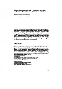
Figure 1. Given a pre-segmented object (a), we derive support substructures (b), which provide structural organization of object parts. Such high-level substructures enable applications such as structure rearrangement (c) and structure synthesis (d), automatically turning a single model or a small set of models to many new nontrivial, functionally plausible variations. Interactive synthesis permits explicit user control over the design (e). puppetry [8], upright shape orientation determination [2], furniture layout synthesis [9], furniture design [10], self-supporting surface design [11], [12], [13], freeform architecture design [14], structural analysis for 3D printing [15], balanced shape design [16] etc. Like ours, most of these works determine static stability via geometric validation instead of physical simulation or validation [10]. We believe that our derived support substructures can potentially benefit some of these applications, besides those demonstrated in the paper. Our analysis of part-level relationship is conceptually related to [17], [18], which, however, rely on neither support nor stability. It is well known that symmetry provides a strong cue for high-level understanding of shapes exhibiting rich symmetry. This has motivated a series of symmetry detection algorithms and symmetry-based applications (see an insightful survey in [19]). Symmetry can be used to form a hierarchical organization of object parts [20]. However, it is unclear how such a general symmetry hierarchy could be exploited for applications like ours. Very recently, Zheng et al. [3] introduce a symmetric functional arrangement, called S FARR , which always contains a triplet of shape parts, with one part stably supported by or supporting another two symmetric parts. With such a simple representation a diverse set of plausible model variations can be synthesized from a small set of input models. However their technique is inapplicable to other rich substructures, e.g., with different numbers of symmetric elements or no symmetry at all. In addition how to apply their technique to our other applications is also unclear. In contrast symmetry is not inherent in our support-induced substructures, though our representation does make use of the symmetry information if any and naturally supports not only S FARR but also different types of symmetric or
non-symmetric arrangements. The very recent work by [4] presents a topology-varying structural blending algorithm, where symmetry also plays a critical role to produce continuous and plausible in-betweens undergoing topology variations. Semi-automatically or automatically synthesizing new shape variations from existing models has been of a great interest in recent years. The main goal is to generate hundreds and thousands of models with little or even no user intervention, which otherwise would be a rather tedious process for commercial modeling systems like Autodesk Maya. Below we only review the most relevant works to ours. Bokeloh et al. [21] present an inverse procedural modeling system which examines partial symmetries of a single 3D example model to automatically produce new 3D models that are similar to the input exemplar. Merrell et al. [22] provide a general procedural modeling method to synthesize complex 3D shapes, based on various dimensional, geometric, and algebraic constraints. Quite recently, Wonka et al. [23] introduce a meaningful split grammar for facade layout interpretation, and then an inverse procedure modeling approach for facade manipulation. Given a pair of input shapes the part-based recombination approach by Jain et al. [24] is able to automatically instantiate new models that have similar symmetry and adjacency structure to the input shapes, but with different appearance. Xie et al. [25] present a reshuffle-based technique for generating a diverse set of non-trivial scene variations from only a small set of input scenes, instead of a sufficiently big training set of 3D scenes used in [26]. Assuming the availability of labeled parts or explicit part correspondence, several approaches demonstrate that many more in-class variations can be created given a larger database of input models with the same class, either automatically [27], [28] or inter-
1077-2626 (c) 2015 IEEE. Personal use is permitted, but republication/redistribution requires IEEE permission. See http://www.ieee.org/publications_standards/publications/rights/index.html for more information.
This article has been accepted for publication in a future issue of this journal, but has not been fully edited. Content may change prior to final publication. Citation information: DOI 10.1109/TVCG.2015.2473845, IEEE Transactions on Visualization and Computer Graphics
IEEE TRANSACTIONS ON VISUALIZATION AND COMPUTER GRAPHICS, VOL.XX, NO.XX, XX XXXX
3
c b
a a
b f
(a)
(b)
(c)
(d) c
Figure 2. We assume that the direction of a support relation between a pair of building blocks is one-way, like those in (a)–(c). See a counterexample in (d), where the three leg parts support each other and it is thus hard to tell which supports which. The graphs in (c) and (d) illustrate the support relation graphs.
actively [29]. Similar to [3] our work aims for the synthesis of both in-class and across-class variations, without explicit part correspondence. We show shape synthesis applications that take a single, two or more models as input. None of the existing methods has demonstrated to work for all our applications.
3
S UPPORT S UBSTRUCTURES
In this section we first introduce the definition of support substructures and then present an algorithm to detect such substructures in an input pre-segmented model. We will show three applications of the detected substructures in Section 4. 3.1
Definitions and Assumptions
Support relations. Objects, especially man-made ones, can often be decomposed into a set of building blocks (Figure 2 (b) and (c)), which are connected by certain support relations to make the objects stable. In this work we explore three types of commonly seen support relations, namely “support from below”, “support from above”, and “support from side”, as illustrated in Figure 3. As we will show shortly that while these relations look simple they are surprisingly sufficient to produce rich support substructures. A support relation is essentially a binary relation, defined between a pair of building blocks. We assume that the direction of a support relation can be always geometrically determined and is one-way. This assumption is applicable to support relations existing in many man-made objects (e.g., Figures 2 (b–c) and 3). However, it is not always valid. For instance, we are not interested in a pair of parts that support each other. Figure 2 (d) shows such a counterexample. Under this assumption a support relation, denoted as ≤, brings a partial order to a set of building blocks of an object, denoted as M . Specifically, for all elements a, b, and c in M , ≤ satisfies: 1) reflexivity: a ≤ a, a building block a supports itself naturally; 2) antisymmetry: if a supports b and b supports a at the same time, we have a = b; 3) transitivity: as illustrated in
d
Support from below Support from above Support from side
e
Figure 3. The support relations (“support from below”, “support from above” and “support from side”) between parts of a pre-segmented model (e) are represented as a support relation graph (f). (a-d): a subset of detected support structures, with supporting components shown in green and supported ones in red.
Figure 2 (a), if a supports b (i.e., a ≤ b) and b supports c (i.e., b ≤ c), we can conclude a supports c, i.e., a ≤ c. Our three types of support relation over M lead to a partially ordered set (M, ≤), also called a poset in set theory. Such a poset can be equivalently represented as a support relation graph, which is essentially a directed acyclic graph (DAG), with set elements as nodes and binary relations as directed edges, pointing from supporting elements to supported ones (Figure 3). A similar support relation graph has been explored in [6], but used only for predicting support order. Support substructures. A support substructure is formed by a subset of our poset or a subgraph of our support relation graph. A desired definition of support substructure should not only allow the extraction of a rich set of substructures from an object but also effectively help form functionally plausible new variations for various applications. Our definition of support substructure is an extension of a primitive support substructure. A primitive support substructure contains an ordered pair of primitive elements (a, b) with a stably supporting b, i.e., a ≤ b. That is b can achieve static equilibrium with the support from a, as illustrated in Figure 2 (a). Let {a} � {b} (Figure 4 (a)), with � meaning a stable support relation, denote such a primitive substructure, which is consistently observed across objects (e.g., Figure 3 (c)). It is very often that a group of elements with very similar or even the same shape, denoted as As , together stably support a primitive part b (e.g., four chair legs supporting a seat in Figure 2 (b)). We thus also consider As �T {b} (Figure 4 (b)) as a support substructure if the type of support relation T between b and a, ∀a ∈ As , is the same. See another example in Figure 3 (b). Since similar elements are perceptually
1077-2626 (c) 2015 IEEE. Personal use is permitted, but republication/redistribution requires IEEE permission. See http://www.ieee.org/publications_standards/publications/rights/index.html for more information.
This article has been accepted for publication in a future issue of this journal, but has not been fully edited. Content may change prior to final publication. Citation information: DOI 10.1109/TVCG.2015.2473845, IEEE Transactions on Visualization and Computer Graphics
IEEE TRANSACTIONS ON VISUALIZATION AND COMPUTER GRAPHICS, VOL.XX, NO.XX, XX XXXX
grouped together, no subset of As is allowed to form a substructure with others. Similarly our support substructure also extends to {a} �T Bs (e.g., an airplane body supporting two wings as shown in Figure 3 (d)), where a is a primitive part, Bs is a group of similar parts, and a stably supports any part in Bs with the same support relation T (Figure 4 (c)). In short, our extension of support substructures is applicable to a group of similar elements connected to a single element with the same support relation. This also extends to hierarchial grouping of similar elements like the example shown in Figure 3 (a), where we have two wings connected to the body (as a single node) and two turbine engines connected to each of the wings. Note that the S FARR substructure [3] is only a special case of our support substructures. The primitive support substructure can also be extended to Ac �T {b} (Figure 4 (d)), where Ac denotes the entire set of elements with the same support relation to primitive element b and together stably supporting b. Here individual elements of Ac are not necessarily of similar shape (Figure 2 (c)). To keep the stability of an existing substructure, a subset of Ac is not allowed to form a new substructure with b. However, it is possible that individual elements of Ac form new substructures with other elements supporting them. In other words, individual elements of Ac , as supported components, can form new substructure. Bs b
a
a
(a)
b
b
As (b)
(c)
Ac (d)
Figure 4. Four kinds of basic support substructures. We call {a} � {b}, As �T {b}, {a} �T Bs , and Ac �T {b} basic support substructures (Figure 4), since both the supporting and supported components of such a substructure involve only one layer of elements. Many objects exhibit support in hierarchy, i.e., one part supporting the other in single or multiple hierarchy. In case of support in multiple hierarchy, a part is supported by other parts at different hierarchies (Figure 2 (c)). We thus extend the definition of support substructure by support in multiple hierarchy. Specifically, let A1 �T1 B1 and A2 �T2 B2 denote two support substructures, with A1 ∩ B2 �= ∅ and B1 ∩ A2 = ∅. In other words, A1 and B2 share certain object parts. Then a new support substructure with an increased hierarchy level can be created by combining the given two substructures, leading to two possible combinations: either A1 ∪B2 ∪A2 �T1 B1 or A2 �T2 B2 ∪ A1 ∪ B1 , as illustrated in Figure 5. Iteratively combining newly created substructures leads
4
S S S
S
S
S
S
A
S A A
S S
S A
H
S S
H
H S
S
H
H
S
A
H
A
H
A
H A
Figure 5. Illustration of support substructures combination. S: support from below; H: support from above; A: support from side. to substructures with support in (possibly multiple) hierarchy. Remark. It can be easily seen that if a group of similar parts connected to a part is considered as a unified element, any support substructure by our definition essentially forms an upper semilattice, which is a subset of our poset with a least upper bound for any nonempty finite subsets. 3.2
Detection
We focus on man-made objects that have a known upright orientation [2]. Whether an entire input model is “supported from below” (e.g., by the ground) or “supported from above” (e.g., hung from a ceiling) is also given as input to our algorithm. Below we will explain the algorithm in the context of an input model placed on the ground. Adapting the algorithm to a model supported from above is straightforward. Pre-segmentation. We require the availability of semantically meaningful segments for the input model. In our implementation, we segment an input model by using an SDF-based mesh partition method [30] and manually adjust the automatically generated segmentation results, if necessary. See such a segmented model in Figure 8 (a). Support relation graph. To identify support substructures, we first build a support relation graph, denoted as G (Figure 8 (b)) as follows. Each object part leads to one node in the graph. All the nodes whose corresponding parts touch the ground plane are marked as ground-touching nodes, denoted as Vg (e.g., the five nodes in dark green in Figure 8 (b)). A pair of components a and b are determined to be connected if their convex hulls intersect at several points (more than 5 in our experiment) or the minimal distance between them is below a threshold δ (Section 5). With Principal Component Analysis (PCA) we approximate a plane P using the points where a and b are in contact, as illustrated in Figure 6. We first locally classify the type of support between a and b (Figure 6). a and b have a “support from side” relation if the normal of P is nearly perpendicular to the upright orientation (deviation angle ≤ 10o ). Otherwise we temporarily assign a “support from below”
1077-2626 (c) 2015 IEEE. Personal use is permitted, but republication/redistribution requires IEEE permission. See http://www.ieee.org/publications_standards/publications/rights/index.html for more information.
This article has been accepted for publication in a future issue of this journal, but has not been fully edited. Content may change prior to final publication. Citation information: DOI 10.1109/TVCG.2015.2473845, IEEE Transactions on Visualization and Computer Graphics
IEEE TRANSACTIONS ON VISUALIZATION AND COMPUTER GRAPHICS, VOL.XX, NO.XX, XX XXXX
a b support from below
a b support from side
Figure 6. An illustration to show how to determine the “support from side” and “support from below” relations. directed path
3
3
6
1
7
2
7
2
8
5
3 8
5
1
Rectify
t
4
7
2
6 1
8
5 4
4
region grow Vg nodes
Vg nodes
6
(a)
change relation Vc nodes Vr nodes
(b) directed path 7
2 3 1
5 4
relabel Vg
7
2 3
6 8
1
Rectify
5
Vg nodes
(c)
3 8
6
1
4
region grow
7
2
6
5
8
4
change relation Vc nodes Vr nodes
(d)
Figure 7. An illustration to show how we iteratively rectify “support from below” (arrows in red) as “support from above” (arrows in green).
relation to a and b, and add a directed edge from the one below the plane to the other. After all pairs of connected parts are examined, we add a directed edge between each pair of object parts, denoted as c and d, with “support from side”. Specifically, a directed edge from c to d (i.e., c ≤ d) is added if there is an undirected path between c and some of the groundtouching nodes. Locally it is difficult to distinguish between “support from below” and “support from above”. Since the input model is placed on the ground, “support from below” was initially used, as illustrated in Figure 7 (a). Now we perform region growing starting from the ground-touching nodes Vg to iteratively find “support from above” (Figure 7 (b)). Specifically, we first identify all the nodes Vc , to each of which there is a directed path from a node in Vg . Let Vr denote the rest of the nodes. We change the relation from “support from below” to “support from above”, and correspondingly reverse the direction for such edges between Vc and Vr , and among Vr . Then in Vr we label nodes which touch Vc as Vg (Figure 7 (c)) and repeat the above steps until all the nodes are visited (Figure 7 (d)).
5
Support substructure. As discussed previously, a support substructure is essentially a subgraph of the support relation graph G. For each group of similar parts As connected to a single part, we first reduce the graph G by contracting the nodes corresponding to As and replacing them with a single node, followed by necessary updates on the set of edge connectivity (Figure 8 (c)). This reflects the requirement that no subset of As is allowed to form a substructure with others. This process is repeated until each level of hierarchial grouping of similar parts leads to a single node in the graph. Like the previous works (e.g., [3], [5]), we determine static stability via geometric validation. Specifically, given a group of elements B with multiple supports from another group of elements A, we say B is stably supported by A if the projection of B’s center of mass to the ground falls inside the convex hull of the projection of the multi-supporting areas from A to the ground. In G we also contract a pair of nodes a and b if b is supported by a only but the support is unstable. The static stability analysis often does not work for “support from side”, where stable support is typically achieved by other means like nail joints. Since stability provides a strong cue for the extraction of meaningful substructures by analyzing the geometry alone, we first search for support substructures among the parts connected by “support from below” and/or “support from above”. To achieve this, we temporarily break the edges with “support from side” in G, leading to a set of weakly connected subgraphs {Gi } (Figure 8 (d)). We take a bottom-up approach to search for all basic support substructures in each subgraph Gi . First, we determine the support order starting from the groundtouching nodes, using a level order traversal approach similar to [6]. The order prediction is performed on a transitive reduction of a copy of Gi . Otherwise the predicted order would be undesired in case of support by multiple hierarchy. Second, from the lowest order, for each node a we search for a basic support substructure that contains a. Specifically, let b be the node directly supported by a. If b is supported by multiple nodes including a, we check the stability of b against the set of multiple nodes. If they are stable, b and the set of multiple supporting nodes form a support substructure. The above steps are repeated until all the nodes are visited. To get the basic support substructures purely formed by “support from side”, we break the edges in G with “support from below” and “support from above”. We then use a similar bottom-up approach but without stability validation to identify those support substructures in the resulting subgraphs. Finally we combine the basic support substructures (Section 3.1), which possibly involve different support types, to form new substructures in multiple hierarchy (Figure 8 (e)). The more rounds we combine, the
1077-2626 (c) 2015 IEEE. Personal use is permitted, but republication/redistribution requires IEEE permission. See http://www.ieee.org/publications_standards/publications/rights/index.html for more information.
This article has been accepted for publication in a future issue of this journal, but has not been fully edited. Content may change prior to final publication. Citation information: DOI 10.1109/TVCG.2015.2473845, IEEE Transactions on Visualization and Computer Graphics
IEEE TRANSACTIONS ON VISUALIZATION AND COMPUTER GRAPHICS, VOL.XX, NO.XX, XX XXXX
6
SS ing
SS Group
SS a
b 1
ing
Decompose
c 2
d SSed
5
3
(a) Contact Slots.
ed
f SS ed = 2
fSS ing = 1
(b) Context Compatibility.
Figure 9. Illustration for contact slots (dots in orange) and context compatibility.
4 8 7
6
e
Figure 8. Support substructure detection starts with basic support substructures (1, 2, 3, 4). Substructures with support in hierarchy are obtained by combining basic substructures: after 1st round → 5 and 7; after 2nd round → 6 and 8. The combination order shows the hierarchy attribution of support substructures.
more complicated substructures we get. In general, the number of rounds for substructure combination is application dependent. However, we found 1-2 rounds are already sufficient for our applications to synthesize many nontrivial shape variations.
4
A PPLICATIONS
In this section we introduce three applications, where support substructures play a major role and make the synthesized models structurally valid and functionally plausible. In the first application (Section 4.1), we reshuffle compatible support substructures from two or more different models to create new shape variations. In the second and third applications we show how to synthesize new shapes given a single model by re-arranging (Section 4.2) or duplicating (Section 4.3) compatible support substructures. The common idea behind these three applications is to perform the modeling process with the support substructures as building blocks. By decomposing each shape into a set of support substructures, we get a structural organization of parts. Our carefully designed operating rules for different applications respect the encoded relationships between parts in the detected support substructures and thus produce functionally plausible modeling results. Let SS ing � SS ed denote a basic or multi-hierarchy support substructure, where SS ing and SS ed (Figure 9 (a)) are the supporting and supported components of the substructure, respectively. 4.1
Shape Reshuffling
This application is motivated by the recent work of Zheng et al. [3], which creates new in-class or
across-class shape variations by reshuffling compatible symmetry-induced substructures, called S FARR-s. We will show that our support-induced substructure representation is able to create many more variations, which received higher scores by the user study participants than those by S FARR. Given n (n ≥ 2) input objects, which are possibly from different model families, with pre-computed segmentation but not necessarily having explicit part correspondence, we first detect a set of support substructures Si = {s1i , s2i , ..., ski i } for each object (Section 3.2). Let S = {S1 , S2 , ..., Sn }. We then cluster all support substructures in S by the type of support, leading to 3 clusters, corresponding to 3 support types. In each cluster, we sort the support substructures by their bounding box size. For a pair of support substructures si and sj in each cluster, we measure structure compatibility γ(si , sj ) based on the difference in terms of scale, contact, and context. Specifically, γ(si , sj ) = λ · θ · β,
(1)
where λ measures the scale compatibility between the corresponding supporting and supported components in si and sj at the bounding box level (see a similar definition in [3]). Let θi denote the volume of the convex hull formed by the contact slots (Figand SSsedi . We then have ure 9 (a)) between SSsing i θ = g(θi , θj ) to compare the difference of component contact between si and sj , where g(x, y) = 1 + |x − y|/|x + y|. Finally β measures context compatibility, i.e., the difference of the context of si and sj in Tl their original models. Specifically, let fSS ed denote the number of support relations of type Tl between SS ed and the other object parts which are not in the substructure of interest but connected to SS ed . For example, the supported component (in red) in Tl Figure 9 (b) has fSS = 2, with Tl = “support ed from below”. Note we count 1 for each group of similar parts (e.g., the two chair arms). �6 By similarly Tl k k introducing fSS ing , we compute β as k=1 g(Di , Dj ), T1 T2 T3 T1 T2 T3 where Di = (fSS ed , fSS ed , fSS ed , fSS ing , fSS ing , fSS ing ) i i i i i i is a 6D context compatibility descriptor. Figure 10 (a) and (b) shows four variations by performing reshuffling twice. It is shown that when the structure compatibility γ is of small values, the
1077-2626 (c) 2015 IEEE. Personal use is permitted, but republication/redistribution requires IEEE permission. See http://www.ieee.org/publications_standards/publications/rights/index.html for more information.
This article has been accepted for publication in a future issue of this journal, but has not been fully edited. Content may change prior to final publication. Citation information: DOI 10.1109/TVCG.2015.2473845, IEEE Transactions on Visualization and Computer Graphics
IEEE TRANSACTIONS ON VISUALIZATION AND COMPUTER GRAPHICS, VOL.XX, NO.XX, XX XXXX
s1
s1
s2 ���1,s2 )=1.105
a
s2
s1
s1
���1,s2 )=1.214
b
s2
7
���1,s2 )=5.672
c
s2
���1,s2 )=4.824
d
Figure 10. Shape reshuffling once (a) and twice (b). Note that such reshuffling results are difficult to synthesize with sFARR due to the lack of proper triplets of shape parts between models. (c) and (d) show two examples rejected by our technique due to their high structure compatibility costs. corresponding reshuffling results are generally of high quality. In contrast, high structure compatibility costs often lead to unpleasing results, as shown in Figure 10 (c) and (d). We thus perform reshuffling greedily, starting from a pair of support substructures (from different input objects) with the minimum value of γ(si , sj ). In this way, many functionally implausible results can be effectively avoided. User Study. We conducted a user study to evaluate the quality of new shape variations achieved by reshuffling. We applied our reshuffling technique to the main inputs tested by [3]. There were in total 5 different sets of input models (see the thumbnails in Figure 11 (left)), varying from 3 to 6 models. For each set of input models, we automatically synthesized 100 models, each of which came with an increasing value of γ(si , sj ). Please refer to our supplemental materials for the detailed reshuffling results. The 500 results by our technique, together with the unique results by S FARR (more details later), were presented in a random order to in total 60 participants (all of them were university students), who were asked to rate every synthesized shape on a discrete scale from 1 (worst) to 5 (best). They were suggested to give a score for each model based on their own answers to the following questions: “are they coherent with your understanding of man-made objects?” and “how likely a similar object would appear in reality?”. To check whether a reshuffling result with a lower structure compatibility value would receive a higher score by the participants, we calculated the average score given the participants for the first k synthesized models (with increasing values of γ(si , sj )), 1 ≤ k ≤ 100, in each set of models. As seen from Figure 11 (left), the average score for each set overall decreased with k, the number of synthesized models, indicating an effective quality control by γ(si , sj ). This figure also suggested that the top 40 results were often reasonably good (with average score ≥ 3.5) and the
top 80 results were still acceptable (with average score ≥ 3.0). Comparison with S FARR. When a triplet of parts with the special arrangements required by S FARR appears in the object, it will also be detected by our algorithm as a support substructure. S FARR is thus only a special type of support substructure. Our support substructure representation is more general and exists beyond symmetric arrangements. It supports multiple hierarchy and does not restrict the number of elements. Theoretically our technique is able to reproduce all the results shown in [3]. However, due to the adoption of different compatibility metrics, 39 out of their 106 results (Figures 1, 12 and 14 of [3]) were not in the set of the 500 results by our technique. The quality of these 39 results was rated by our participants during the user study. Our technique produced many more reshuffling results. It is more important to verify whether our results are comparable to or even better than those by S FARR. To this end, from the top 80 results in each set we randomly sampled the same number of results as the corresponding set in [3], and calculated the average scores for the sampled results and the results by S FARR, respectively. Each of their result sets contained 11 to 35 models. For fairer comparisons, the above process was repeated for 10 times for each set of input models. It was found that our results were rated consistently and significantly higher than those by S FARR, as confirmed by t-tests (p-value < 0.05 in all cases). This is possibly because the unique results by S FARR were rated relatively poorly, as shown in Figure 11 (f). For each set of input models, Figure 11 (a–e) shows a box-and-whisker plot of the scores of the 10 sets of our randomly picked results and the corresponding sets of results by S FARR. Figure 12 shows around top-30 results by applying our reshuffling technique to new sets of input models. Many of the results (e.g., those highlighted in yellow) would be difficult to produce by S FARR due to the
1077-2626 (c) 2015 IEEE. Personal use is permitted, but republication/redistribution requires IEEE permission. See http://www.ieee.org/publications_standards/publications/rights/index.html for more information.
This article has been accepted for publication in a future issue of this journal, but has not been fully edited. Content may change prior to final publication. Citation information: DOI 10.1109/TVCG.2015.2473845, IEEE Transactions on Visualization and Computer Graphics
IEEE TRANSACTIONS ON VISUALIZATION AND COMPUTER GRAPHICS, VOL.XX, NO.XX, XX XXXX
5 set1 set2 set3 set4 set5
4.5 4
5
5
5
4.5
4.5
4.5
4
4
4
3.5
3.5
3.5
3
3
3
2.5
2.5
2.5
2
2
3.5
1.5
a
1
1
3 2.5
set 1
set 2
2 1.5
6
5
7
8
9
10
11
5
10
15
20
25
30
40
45
50
55
60
65
70
75
80
85
90
95
100
1
5
5 4.5
4
4
3.5
3.5
3
3
2.5
2.5
1
b 1
2
3
4
5
6
1.5
set 2 7
8
9
10
1
11
1
2
3
4
5
6
set 4 7
8
9
10
1
11
2
3
4
5
6
7
8
9
10
11
4.5 4 3.5 3 2.5 2 1.5
1.5
d
set 3
c 1
5
2
1.5
35
2
1.5
4.5
2
set 5 1
4
3
2
set 1
set 4
set 3
8
e 1
2
3
4
5
6
set 5 7
8
9
10
f
1
11
10
sFarr
20
30
40
Figure 11. Left: the average score rated by the participants overall decreased with the number of reshuffling results, indicating the effectiveness of our structure compatibility metric. (a)–(e): box-and-whisker plots of the scores of our results and S FARR’s results for each set of input models. In each plot, the first 10 boxes are for 10 sets of our randomly-picked results and the 11th for S FARR’s results. (f): the user-rated score of each of the unique models by S FARR. please refer to the supplemental materials for the detailed results. lack of necessary symmetry parts in the input objects. However, we also admit that the flexibility of our representation is at the cost of slightly more complicated operations towards functionally plausible reshuffling results. 4.2
Structure Rearrangement
Our support substructures give a structural decomposition of an input object. Each support substructure is structurally valid and thus can be used as a whole for shape editing. Based on this observation, we introduce a shape rearrangement application, which automatically rearranges substructures to create nontrivial variations from a single input model. This application is more like an in-model reshuffling. For simplicity, we perform rearrangement operations in 2D (ground plane) only. Again let S = {s1 , s2 , ..., sn } denote a set of support substructures for an input model, which is often a scene model for creating more variations. Again we first cluster the substructures by support type, leading to 3 clusters. We then align the support substructures in each cluster by registering their supporting components SSiing via Iterative Closest Point (ICP). The substructures with small alignment errors are grouped together. Denote the resulting groups as G = {g1 , g2 , ..., gm }. To create interesting rearrangement results we drive rearrangement mainly by a principal group gˆ ∈ G, which has the biggest bounding box size. For example the support substructures 2, 5, and 7 in Figure 1 form such a principal group. Every pair of substructures in gˆ have their supporting components well aligned. We thus can switch between two substructures in gˆ for structure rearrangement, without destroying the contact conditions in the 2D plane. Specifically structure rearrangement is achieved by a two-step approach, as illustrated in Figure 13:
si
Switch Step
si
sk i
sk i
sj
sl j
sl j
sl i
sl i
Relocate Step
sj
Figure 13. Illustration of two-step structure arrangement.
(1) Iteratively switch between pairs of support substructures in gˆ. We randomly select an unvisited pair of support substructures si , sj ∈ gˆ and then replace with each other. After si is replaced with sj , sj might need rotated to avoid severe intersection with the existing substructures originally adjacent to si . We use mesh collision detection to check the availability of severe intersections, specifically by checking whether the ratio between the intersection part and the original model is below a threshold ε (Section 5) or not. The height of the existing substructures which are originally connected with SSsedi is adjusted to get well connected to sj . This process is repeated till no unvisited pair is found or the number of iterations exceeds a user-specified number (e.g., 20). (2) Iteratively relocate support substructures from non-principal groups. For each support substructure ski in a non-principal group gk , we examine whether it is possible to relocate ski to a new position. We first find a support substructure sli from another nonprincipal group ∈ gl (�= gk ), which shares the largest number of supporting components with ski . We can then relocate ski to get connected to slj ∈ gl , since sli and slj are well aligned and thus slj is very likely to well support the relocated version of ski . The new location of ski is determined by first aligning ski with sli using their shared components and then transforming ski by the optimal transformation between ski and slj . ski might need rotated to avoid intersecting with the
1077-2626 (c) 2015 IEEE. Personal use is permitted, but republication/redistribution requires IEEE permission. See http://www.ieee.org/publications_standards/publications/rights/index.html for more information.
This article has been accepted for publication in a future issue of this journal, but has not been fully edited. Content may change prior to final publication. Citation information: DOI 10.1109/TVCG.2015.2473845, IEEE Transactions on Visualization and Computer Graphics
IEEE TRANSACTIONS ON VISUALIZATION AND COMPUTER GRAPHICS, VOL.XX, NO.XX, XX XXXX
9
Figure 12. Four sets of shape reshuffling results by our technique. Note that each set contains around top-30 results, without cherry picking. The input models are those with colored parts. The results highlighted in red are less visually appealing, and those highlighted in yellow are difficult to synthesize by S FARR. 1077-2626 (c) 2015 IEEE. Personal use is permitted, but republication/redistribution requires IEEE permission. See http://www.ieee.org/publications_standards/publications/rights/index.html for more information.
This article has been accepted for publication in a future issue of this journal, but has not been fully edited. Content may change prior to final publication. Citation information: DOI 10.1109/TVCG.2015.2473845, IEEE Transactions on Visualization and Computer Graphics
IEEE TRANSACTIONS ON VISUALIZATION AND COMPUTER GRAPHICS, VOL.XX, NO.XX, XX XXXX
existing substructures. The relocation step is repeated till we reach a user-specified number (e.g., 20). Results. Different from the application of shape reshuffling, which needs a relatively large set of substructures to create many variations, structure rearrangement is already able to create many new functionally plausible shapes with a relatively small number of support substructures. Hence for this application we only combine basic substructures for one round (Section 3.2). Figure 1 shows the rearrangement results after three iterations. Please refer to Figure 14 and the supplemental materials for more rearrangement results. 4.3 Structure Synthesis The application of shape rearrangement essentially changes only the locations of support substructures. Now we show another application which turns a single input model to new nontrivial variations by duplicating substructures and connecting them together, in a spirit of procedural modeling. We follow the notations introduced in Section 4.2. We will first present the main idea using a 2D example and then discuss its extension to 3D synthesis. Structure Synthesis. As illustrated in Figure 15, it is operated among the substructures in the principal group gˆ. Each time a pair of support substructures si , sj ∈ gˆ are randomly selected. If there exists a 2D transformation Tij which can link si with sj , and the transformed si does not seriously intersect with the other support substructures, si is then copied and transformed to link with sj . Tij (si ) is added to G (Figure 15 (right column)). This process is repeated until there exist no such a pair of substructures or it reaches the prescribed number of iterations. Below we give the details on the definition of Tij . T34
2 grow direction
1
3
4
4
3
grow direction
in
3
4
45
45
grow direction
dout din
5
2
1 3
4 5
3 4
3
4
Figure 15. Illustration of Tij and the structure synthesis process. Left column: the contact descriptor is calculated for the principal group gˆ containing 5 support substructures. Middle column: local view of s3 and s4 . Right column: a support substructure is newly duplicated under the 2D transformation of T 34 . Definition of Tij . To define Tij we first introduce a contact descriptor between si ∈ gˆ and any other
10
substructure sj ∈ S (Figure 15 (left column)). Specifically the contact information between si and sj is analyzed in three aspects: (1) a set of sharing parts between the supporting components of si and sj , i.e., ∩ SSsing ; (2) the inner direction din Aij = SSsing ij from i j the centroid of Aij to the centroid of SSsedi , (3) the from the centroid of Aij to the outer direction dout ij ed centroid of SSsj . This leads to a contact descriptor out Dij = {Aij , din ij , dij } for si and sj . It is easy to see in in that Aij = Aji , dij = dout ji . Note that the directions dij out and dij are both 2D vectors. Finally we get a contact descriptor set Di = {Dik |Aik �= ∅} for each si ∈ gˆ. To encourage forming more links between a pair of substructures in the principal group and thus creating more variations, we try to add more potential contact information from each of other substructures in gˆ, denoted as sl , to si . Specifically, we compute a 2D transformation T li : sl → si that best aligns to SSsing . The contact descriptor Dl of sl is SSsing i l transformed by T li as T li (Dl ) = {T li (Dlk )} with li out T li (Dlk ) = (T li (Alk ), T li (din lk ), T (dlk )). si ’s contact descriptor set is then updated as Di = Di ∪ T li (Dl ). Now for each si ∈ gˆ we have Di = {Dik = out ˆ, they can get linked (Aik , din ik , dik )}. Given si , sj ∈ g together iff there exists a 2D transformation T such that (1) T (Aik ) = Ajl , i.e., the sharing supporting out components get well aligned; (2) T (din ik ) = djl , the in inner direction d of si is aligned with the outer diin rection dout of sl ; (3) T (dout ik ) = djl , the outer direction out of si is consistent with the inner direction din of d sl . We also use mesh collision detection to check the availability of severe intersections. This simple rule forms the basis for our structure synthesis procedure. Results. Figure 16 shows several results created by our structure synthesis enabled by support substructures. Our work bears some resemblance to inverse procedural modeling, in particular the work by Bokeloh et al. [21]. However unlike [21], which requires the detection of partial symmetry regions, our technique relies on support and stability. Both of the techniques are able to produce unique results. See one more example in Figure 1. Interactive synthesis. We also present a simple interface to permit explicit user control over the design. The user is allowed to interactively specify a growing direction (arrow in red in Figure 18 (a)) out of possible growing directions (arrows in white in Figure 18 (b)). The user may also specify how many times substructure duplication should be performed. Figure 18 shows interactive structure synthesis in action and Figure 1 (e) gives another interactive modeling result. Please refer to the supplemental material to see more automatically and interactively synthesis results. Extension to 3D Synthesis. We experimented a simple way to perform structure synthesis in 3D, based on the following observation: given two support substructures s1 and s2 , we can conclude that s2 can
1077-2626 (c) 2015 IEEE. Personal use is permitted, but republication/redistribution requires IEEE permission. See http://www.ieee.org/publications_standards/publications/rights/index.html for more information.
This article has been accepted for publication in a future issue of this journal, but has not been fully edited. Content may change prior to final publication. Citation information: DOI 10.1109/TVCG.2015.2473845, IEEE Transactions on Visualization and Computer Graphics
IEEE TRANSACTIONS ON VISUALIZATION AND COMPUTER GRAPHICS, VOL.XX, NO.XX, XX XXXX
11
Figure 14. Gallery of automatic shape rearrangement results. The input models are in yellow.
Figure 16. Automatic structure synthesis enabled by support substructures. Please refer to Figure 14 for the input models.
1077-2626 (c) 2015 IEEE. Personal use is permitted, but republication/redistribution requires IEEE permission. See http://www.ieee.org/publications_standards/publications/rights/index.html for more information.
This article has been accepted for publication in a future issue of this journal, but has not been fully edited. Content may change prior to final publication. Citation information: DOI 10.1109/TVCG.2015.2473845, IEEE Transactions on Visualization and Computer Graphics
IEEE TRANSACTIONS ON VISUALIZATION AND COMPUTER GRAPHICS, VOL.XX, NO.XX, XX XXXX
stably support s1 if sed 2 (the supported component of (the supporting component of s2 ) stably supports sing 1 s1 ). This motivates us to perform synthesis along the SUPPORT direction. Specifically, we first randomly select two support substructures si and sj ∈ gˆ. We then find a 2D rotation and 2D translation to align the projected centers of si and sj . Finally we translate the transformed si along the SUPPORT direction until the well touch sed slots of sing j . This process is repeated i until there exist no such a pair of substructures or it reaches the prescribed number of iterations. Figure 17 shows a synthesized result.
12
a
b
5 3
3
3
1
1
2
1
2
a
c
b
2
c
Figure 17. After detecting the support substructures of the model, we select 3 support substructures (a). Support substructure 2 is copied and transformed in the SUPPORT direction (supported by support substructure 1) to get support substructure 4(b). Support substructure 3 is copied and transformed in the SUPPORT direction (supported by support substructure 4) to get support substructure 5(b).
5
d
4
4
D ISCUSSION
Parameters. In our experiments we always set δ = 0.05d, where d is the diagonal length of the input model’s bounding box, and intersection error ε = 0.10. The default values for the other parameters were already given in the previous text. Figure 19 illustrates that an improper value of ε would lead to artifacts for structure rearrangement and synthesis. For example, the part highlighted in red (Figure 19 (b)) blocks the way to a sliding board. In Figure 19 (d), severe intersection is not removed due to the improper value of ε. We also analyze the roles of the three support types in the synthesized results. Specifically we collect the frequency of the three support types used in the results produced by our applications. We find that “supporting-from-below” (normalized frequency: 47.05%) and “support-from-side” (normalized frequency: 35.30%) are more popular than “supportingfrom-above” (normalized frequency: 17.65%). This is mainly because most of our tested input models represent objects that are supposed to stably stand on some flat surface (e.g., ground, floor, table, etc.). Time Complexity. For a shape with n parts, the total complexity for substructure detection is O(n2 ). Although n is generally small, in practice the step of connection detection between component pairs
Figure 19. Top: structure rearrangement with ε = 0.10 (a) and ε = 0.20 (b). Bottom: structure synthesis with ε = 0.10 (c) and ε = 0.20 (d). The input model is in Figure 13.
(Section 3.2) is relatively slow due to the convexhull-based intersection. The average time used for substructure detection of each shape in all our experiments is about 1 − 2 minutes, measured on a PC with an Intel Core 2 Duo 2.4 GHz CPU and 16G RAM. Since all the substructures can be detected in a preprocessing step, so the time complexity is still acceptable. Given all the detected substructures, it took on average several seconds to synthesize one reshuffling result. Our structure rearrangement and synthesis can be achieved at interactive rates, as seen in the supplementary video. Limitations. First, similar to other recent high-level shape synthesis methods (e.g., [3], [4], [27], [28]) our method relies on pre-segmentation of good quality. Second, we assume that the direction of support relation graph can be geometrically determined, which is not always possible for example for structurally in-determined structures [11]. The properties (i.e., reflexivity, antisymmetry, transitivity) of our adopted three types of support do not apply to all kinds of support relationships. Like previous symmetry-based synthesis methods [22], which are not applicable to models with little symmetry, our rearrangement and synthesis techniques are designed for shapes with rich self-similar support substructures. Otherwise, it is difficult to produce many interesting variations. Lastly, support relationships themselves might not be sufficient to capture semantic relationships between parts. Therefore, like many other shape understanding systems, our technique may produce interesting but functionally not very plausible results, e.g., those in Figure 20.
1077-2626 (c) 2015 IEEE. Personal use is permitted, but republication/redistribution requires IEEE permission. See http://www.ieee.org/publications_standards/publications/rights/index.html for more information.
This article has been accepted for publication in a future issue of this journal, but has not been fully edited. Content may change prior to final publication. Citation information: DOI 10.1109/TVCG.2015.2473845, IEEE Transactions on Visualization and Computer Graphics
IEEE TRANSACTIONS ON VISUALIZATION AND COMPUTER GRAPHICS, VOL.XX, NO.XX, XX XXXX
a
13
b
c
d
e
Figure 18. Interactive structure synthesis in action. The input model is highlighted in green. The user may interactively control the growing directions (arrows in red) and the number of times for substructure duplication. assumptions, and non-trivial structural optimization based on reassembling and varying parts etc.
ACKNOWLEDGEMENTS a
b
c
d
Figure 20. Interesting but functionally not very plausible reshuffling results.
6
C ONCLUSION
AND
F UTURE W ORK
This work presented the concept of support substructures, a high-level structural representation of object parts based on support and stability, and defined them as special semilattices induced by the support relations as partial order over a set of object parts. Although our definition of support substructure is simple, it enables various applications, including shape reshuffling, structure rearrangement, and structure synthesis, as demonstrated in the paper. None of the previous works is able to handle all these applications in a single framework. The current structure rearrangement and synthesis are operated in 2D only. Since our support substructures already encode vertical hierarchies, it would be interesting to extend these applications to the 3D domain. In the future we are interested in refining or generalizing the definition of support substructure, aiming at higher-level shape editing applications. It is also interesting to study the linkage of the synthesis of structures and perform a more careful stability analysis, e.g., a systematic treatment of force flow and structural stability with more realistic physical
This work was supported by the National Basic Research Project of China (Project Number 2011CB302203), the Natural Science Foundation of China (Project Number 61120106007), Research Grant of Beijing Higher Institution Engineering Research Center, and Tsinghua University Initiative Scientific Research Program. Hongbo Fu was partially supported by grants from the Research Grants Council of HKSAR, China (Project No. 113513, 11204014 and 11300615).
R EFERENCES [1]
[2]
[3] [4] [5] [6]
[7]
R. Gal, O. Sorkine, N. J. Mitra, and D. Cohen-Or, “iWIRES: An analyze-and-edit approach to shape manipulation,” in ACM Trans. Graph., 2009, pp. 33:1–33:10. [Online]. Available: http://doi.acm.org/10.1145/1576246.1531339 H. Fu, D. Cohen-Or, G. Dror, and A. Sheffer, “Upright orientation of man-made objects,” in ACM Trans. Graph., 2008, pp. 42:1–42:7. [Online]. Available: http://doi.acm.org/10.1145/1399504.1360641 Y. Zheng, D. Cohen-Or, and N. J. Mitra, “Smart variations: Functional substructures for part compatibility,” Computer Graphics Forum, vol. 32, no. 2pt2, pp. 195–204, 2013. I. Alhashim, H. Li, K. Xu, J. Cao, R. Ma, and H. Zhang, “Topology-varying 3d shape creation via structural blending,” ACM Trans. Graph., vol. 33, no. 4, 2014. Z. Jia, A. Gallagher, A. Saxena, and T. Chen, “3d-based reasoning with blocks, support, and stability,” in CVPR ’13, 2013. S. Panda, A. Hafez, and C. Jawahar, “Learning support order for manipulation in clutter,” in Intelligent Robots and Systems (IROS), 2013 IEEE/RSJ International Conference on. IEEE, 2013, pp. 809–815. N. Silberman, D. Hoiem, P. Kohli, and R. Fergus, “Indoor segmentation and support inference from RGBD images,” in Computer Vision - ECCV 2012 - 12th European Conference on Computer Vision, Florence, Italy, October 7-13, 2012, Proceedings, Part V, 2012, pp. 746–760.
1077-2626 (c) 2015 IEEE. Personal use is permitted, but republication/redistribution requires IEEE permission. See http://www.ieee.org/publications_standards/publications/rights/index.html for more information.
This article has been accepted for publication in a future issue of this journal, but has not been fully edited. Content may change prior to final publication. Citation information: DOI 10.1109/TVCG.2015.2473845, IEEE Transactions on Visualization and Computer Graphics
IEEE TRANSACTIONS ON VISUALIZATION AND COMPUTER GRAPHICS, VOL.XX, NO.XX, XX XXXX
[8]
[9]
[10] [11] [12]
[13]
[14]
[15]
[16] [17]
[18]
[19] [20] [21] [22]
[23] [24]
[25] [26]
[27]
[28]
X. Shi, K. Zhou, Y. Tong, M. Desbrun, H. Bao, and B. Guo, “Mesh puppetry: cascading optimization of mesh deformation with inverse kinematics,” ACM Trans. Graph., vol. 26, no. 3, p. 81, 2007. L.-F. Yu, S.-K. Yeung, C.-K. Tang, D. Terzopoulos, T. F. Chan, and S. J. Osher, “Make it home: automatic optimization of furniture arrangement,” ACM Trans. Graph., vol. 30, pp. 86:1–86:12, August 2011. [Online]. Available: http://doi.acm.org/10.1145/2010324.1964981 N. Umetani, T. Igarashi, and N. J. Mitra, “Guided exploration of physically valid shapes for furniture design,” ACM Trans. Graph., vol. 31, no. 4, p. Article No 86, 2012. E. Vouga, M. Hobinger, J. Wallner, and H. Pottmann, “Design of self-supporting surfaces,” ACM Trans. Graph., vol. 31, no. 4, pp. 87:1–87:11, 2012. Y. Li, Y. Liu, W. Xu, W. Wang, and B. Guo, “All-hex meshing using singularity-restricted field,” ACM Trans. Graph., vol. 31, no. 6, pp. 177:1–177:11, Nov. 2012. [Online]. Available: http://doi.acm.org/10.1145/2366145.2366196 Y. Liu, H. Pan, J. Snyder, W. Wang, and B. Guo, “Computing self-supporting surfaces by regular triangulation,” ACM Trans. Graph., vol. 32, no. 4, pp. 92:1–92:10, Jul. 2013. [Online]. Available: http://doi.acm.org/10.1145/2461912.2461927 H. Pottmann, A. Schiftner, P. Bo, H. Schmiedhofer, W. Wang, N. Baldassini, and J. Wallner, “Freeform surfaces from single curved panels,” ACM Trans. Graphics, vol. 27, no. 3, 2008, proc. SIGGRAPH. O. Stava, J. Vanek, B. Benes, N. Carr, and R. Mˇech, “Stress relief: Improving structural strength of 3d printable objects,” ACM Trans. Graph., vol. 31, no. 4, pp. 48:1–48:11, 2012. [Online]. Available: http://doi.acm.org/10.1145/2185520.2185544 R. Pr´evost, E. Whiting, S. Lefebvre, and O. Sorkine-Hornung, “Make it stand: Balancing shapes for 3d fabrication,” ACM Trans. Graph., vol. 32, no. 4, pp. 81:1–81:10, 2013. N. J. Mitra, Y.-L. Yang, D.-M. Yan, W. Li, and M. Agrawala, “Illustrating how mechanical assemblies work,” in ACM Trans. Graph., 2010, pp. 58:1–58:12. [Online]. Available: http://doi.acm.org/10.1145/1833349.1778795 M. Lau, A. Ohgawara, J. Mitani, and T. Igarashi, “Converting 3d furniture models to fabricatable parts and connectors,” ACM Trans. Graph., vol. 30, no. 4, pp. 85:1–85:6, 2011. [Online]. Available: http://doi.acm.org/10.1145/2010324.1964980 N. J. Mitra, M. Pauly, M. Wand, and D. Ceylan, “Symmetry in 3d geometry: extraction and applications,” Eurographics Stateof-the-art Report, 2012. Y. Wang, K. Xu, J. Li, H. Zhang, A. Shamir, L. Liu, Z. Cheng, and Y. Xiong, “Symmetry hierarchy of man-made objects,” Computer Graphics Forum, vol. 30, no. 2, pp. 287–296, 2011. M. Bokeloh, M. Wand, and H.-P. Seidel, “A connection between partial symmetry and inverse procedural modeling,” ACM Trans. Graph., vol. 29, no. 4, 2010. P. Merrell and D. Manocha, “Model synthesis: A general procedural modeling algorithm,” IEEE Trans. Vis. Comput. Graph., vol. 17, no. 6, pp. 715–728, 2011. [Online]. Available: http://doi.ieeecomputersociety.org/10.1109/TVCG.2010.112 F. Wu, D.-M. Yan, W. Dong, X. Zhang, and P. Wonka, “Inverse procedural modeling of facade layouts,” CoRR, vol. abs/1308.0419, 2013. A. Jain, T. Thorm¨ahlen, T. Ritschel, and H.-P. Seidel, “Exploring shape variations by 3d-model decomposition and partbased recombination.” Comput. Graph. Forum, vol. 31, no. 2, pp. 631–640, 2012. H. Xie, W. Xu, and B. Wang, “Reshuffle-based interior scene synthesis,” in VRCAI ’13, 2013, pp. 191–198. [Online]. Available: http://doi.acm.org/10.1145/2534329.2534352 M. Fisher, D. Ritchie, M. Savva, T. Funkhouser, and P. Hanrahan, “Example-based synthesis of 3d object arrangements,” ACM Trans. Graph., vol. 31, no. 6, pp. 135:1–135:11, 2012. [Online]. Available: http://doi.acm.org/10.1145/2366145.2366154 E. Kalogerakis, S. Chaudhuri, D. Koller, and V. Koltun, “A probabilistic model for component-based shape synthesis,” ACM Trans. Graph., vol. 31, no. 4, pp. 55:1–55:11, 2012. [Online]. Available: http://doi.acm.org/10.1145/2185520.2185551 K. Xu, H. Zhang, D. Cohen-Or, and B. Chen, “Fit and diverse: set evolution for inspiring 3d shape galleries,” ACM Trans.
14
Graph., vol. 31, no. 4, pp. 57:1–57:10, Jul. 2012. [Online]. Available: http://doi.acm.org/10.1145/2185520.2185553 [29] S. Chaudhuri, E. Kalogerakis, L. Guibas, and V. Koltun, “Probabilistic reasoning for assembly-based 3d modeling,” ACM Trans. Graph., vol. 30, pp. 35:1–35:10, 2011. [Online]. Available: http://doi.acm.org/10.1145/2010324.1964930 [30] L. Shapira, A. Shamir, and D. Cohen-Or, “Consistent mesh partitioning and skeletonisation using the shape diameter function,” The Visual Computer, vol. 24, no. 4, pp. 249–259, 2008. [Online]. Available: http://dx.doi.org/10.1007/s00371007-0197-5
Shi-Sheng Huang is a Ph.D. candidate at Tsinghua University in Beijing, his research interests include: Shape Analysis, Point Cloud Processing and Image Processing.
Hongbo Fu is an Associate Professor in the School of Creative Media, City University of Hong Kong. He received the PhD degree in computer science from the Hong Kong University of Science and Technology in 2007 and the BS degree in information sciences from Peking University, China, in 2002. His primary research interests fall in the fields of computer graphics and human computer interaction. He has served as an associate editor of The Visual Computer, Computers & Graphics, and Computer Graphics Forum.
Ling-Yu Wei is currently a Ph.D. candidate at University of Southern California. Before that, he got his BS degree in Tsinghua University, Beijing, China in 2014. His research interests include: Shape Analysis and Computer Graphics.
Shi-Min Hu is currently a professor in the Department of Computer Science and Technology at Tsinghua University, Beijing. He received the PhD degree from Zhejiang University in 1996. His research interests include digital geometry processing, video processing, rendering, computer animation, and computer aided geometric design. He is associate editor of IEEE TVCG, Computer- Aided Design, Computer and Graphics and The Visual Computer.
1077-2626 (c) 2015 IEEE. Personal use is permitted, but republication/redistribution requires IEEE permission. See http://www.ieee.org/publications_standards/publications/rights/index.html for more information.