purpose systems modeling and optimization software to optimize IMA allocation subject to communication cost and execution time using heuristics for design ...
Deutscher Luft- und Raumfahrtkongress 2012 DocumentID: 281221
SUPPORTING THE DESIGN OF DISTRIBUTED INTEGRATED MODULAR AVIONICS SYSTEMS WITH BINARY PROGRAMMING B. Annighöfer, F. Thielecke, Hamburg University of Technology, Nesspriel 5, 21129 Hamburg, Germany Abstract Distributed integrated modular avionics (DIMA) is a promising concept in aircraft avionics. Aircraft systems share resources like calculation power, memory, and sensor/actuator interfaces. Resources are provided by generalized devices, which can be installed in distributed aircraft locations. Because of the size and complexity, valid and optimal design of such systems is, however, a hard task if carried out manually. It is shown how to support this difficult task by solving subtasks of architectural design as mathematical optimization problems. Allocation problems of both, software mapping and device installation, are formulated as binary integer programs. Those are used to optimize full or sub-parts of avionics architectures for certain objectives, e.g. mass and operational interruption cost, while considering all resource and secondary system requirements. A suitable global optimal solver is proposed for solving resulting combinatorial optimization problems, which are challenging in complexity and size. The potential of the proposed approaches is demonstrated with a reference architecture composed of four redundant aircraft systems. In comparison with manual mappings this reveals optimization potentials up to 45%, while calculation times stay below one minute.
architecture on cable length, weight, cost, reliability, and maintainability of an avionics system, computer-aided design and optimization of IMA/DIMA architectures is a growing field of research.
1. INTRODUCTION The concept of Integrated Modular Avionics (IMA) is sharing avionic resources between aircraft systems for a more efficient avionics system. Resources in terms of computational power and I/O interfaces are provided by standardized hardware.
Sghairi et al. developed a methodology to formally collect and evaluate requirements of a flight control systems, if the system is mapped to a distributed avionics system like IMA [7]. An incremental requirements based design process is used to manually optimize the computing hardware and its distribution.
The first generation of IMA is well established and improves weight, cost, and size of avionics systems [1]. However, there is still optimization potential, e.g. IMA is not capable of hosting every aircraft function owing to time or safety issues. In addition, current implementations do not utilize the full resource sharing capabilities, and could introduce more cable weight than necessary. Therefore, currently the second generation of IMA systems (IMA2G) or Distributed IMA (DIMA) is under development. DIMA includes new device types with extended capabilities and, especially, allows the distribution of devices throughout the aircraft, to achieve shorter cables and better response times [2].
Sagaspe et. al. proposed a combined safety assessment and IMA allocation process [8, 9]. Under consideration segregation and co-allocation constraints they used a constraint solver to derive valid IMA CPU and bus allocations, and showed feasibility for a TF/TA system. Salzwedel and Lohse showed how to use a general purpose systems modeling and optimization software to optimize IMA allocation subject to communication cost and execution time using heuristics for design space exploration [10, 11].
One challenge in designing IMA and particularly DIMA systems is the complexity of these safety critical distributed computing systems. Resource requirements of all individual aircraft systems must be fulfilled, while ensuring that all intra- and inter-system constraints like reliability, segregation, power, etc. hold. Concurrently the designed architecture should be weight and cost optimal on aircraft level [3].
Salomon proposed an approach for automated systems safety computation for IMA hosted systems allowing automated derivation of redundancy structures and allocation of systems to the IMA platform demonstrated with a high-lift system [12]. In this paper approaches are presented for optimizing the static mapping of a set of dependent system functions to a DIMA hardware topology and for mapping DIMA devices to an airplane anatomy. In addition, both approaches optimize for cost and weight quality measures. Baseline for optimization are formal DIMA architecture domain models containing logical system structure, system requirements, hardware properties, and topology as well as aircraft structure. Systems requirements are formalized as a set of consumable resources and mapping constraints. Both problems are formulated as a binary programming problem, which allows solving them globally optimal with state-of-the-art solving techniques. The result
Optimal resource allocation is a well-known problem in the distributed systems domain, e.g. [4, 5, 6]. Most commonly it is focused on a single resource type, e. g. processor time, and time based sharing. For DIMA the spatial distribution is of interest. However, there is a large number of approx. 200 different resource types, which are shared in overlapping combinations. Moreover, most tasks have real-time requirements, and after mapping systems must fulfill minimal safety levels. Because of the complexity of full-airplane architectures, the ever increasing number of avionics functions, and the major impact of the
1
Deutscher Luft- und Raumfahrtkongress 2012
of an optimization is a valid software and hardware mappings optimal to a certain quality measure, which supports the DIMA designer in creating optimal architectures.
ܥ ൌ ሺܶ ǡ ்ܴೖ ሻ
(5)
denotes that task ܶ if hosted to the device consumes the resources specified in the set of resources
This article is organized as follows. Section two presents a novel approach of how to express and solve the mapping problems as binary programs. In section three the implementation is presented, as well as a reference architecture, quality measures, and an optimization experiment to validate and benchmark the proposed approach. Section four outlines the results of the optimization experiments, which are discussed in chapter five.
்ܴೖ ൌ ሺݎଵ ǡ ǥ ǡ ݎ ሻǤ
(6)
The issue is to assign, if possible, every task to a device such that the resources on no device are exceeded. In addition, segregation, device, location, and power constraints have to be considered. More detailed information on the selected modeling and validation approach of DIMA architectures can be found in [15].
2. THEORY It is proposed to express the mapping problems as a binary programming problem. Binary programming minimizes a linear cost function (1)
்݂ ݔ
under consideration of linear inequality constraints (2)
ݔܣ ܾ
which inherently includes equality constraints (3)
ܣ ൌ ܾ Ǥ
The solution vector א ݔሼͲǡͳሽ is restricted to be binary.
2.1.
FIG 1.
Software Mapping
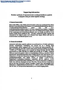
A major task of DIMA planning is to define the distribution of systems functions on the DIMA devices, the so called software mapping. System functions require resources from DIMA modules, which are, most commonly, processor time for running control or monitor applications and I/O interfaces for connecting sensors and actuators, e.g. analogue input pins or discrete pins (cf. [13, 14]). In addition, safety and performance requirements enforce to map some system parts strictly separated or combined [9, 7].
For the software mapping problem an entry ݔ in the solution vector ݔrepresents a unique assignment possibility, i.e. there is a ݔ for each capability on each device for each task.
(7)
The software mapping problem is shown in Fig. 1. Hardware topology and software structure, as well as number and type of resources needed and provided are known. Redundancies are already logically defined, e.g. duplex or triplex structures.
ܶଵ ܥଵ ܦଵ ݔൌ ሺ ݔଵ
ܶଵ ܥଵ ܦଶ ݔଶ
ܶଵ ܥଵ ǥ ǥ
ܶଵ ܥଶ ܦଵ
ܶଵ ǥ ǥ
ǥ ǥ
ܶଶ ǥ ǥ
ǥ ܶே ǥ ܥே ǥ ܦேವ
ǥ ǥ ݔேೣ
ሻ
Where ܰ ڮis the number of elements of the specified type. Consequently, solutions are valid assigning a task more than once. This is prevented by a set of single assignment equality constraints
Each DIMA device ܦ is associated with a set of resources (4)
The software mapping problem. Aircraft system’s software composed of several signal exchanging tasks needs to be mapped to DIMA hardware. The mapping is restricted by constraints and resource availability.
ܴ ൌ ሺݎଵ ǡ ǥ ǡ ݎ ሻ
it provides for hosting functions. �ݎ אԹା is the amount of available resource of resource type ݆. A resource is a representative for anything required and consumed in a quantifiable unit by aircraft systems.
(8)
Aircraft systems are modeled as a set of communicating atomic software blocks called tasks ܶ. A task can be assigned to a device if the device is capable of hosting the task and if the device provides sufficient resources. This is expressed by a set of capabilities ܥassociated to each device type. A capability
ܣ௦
ܶଵ
ǥ
ܶଵ
ܶଶ
ͳ Ͳ ൌ ൮ ڭ Ͳ
ǥ
ͳ
Ͳ ͳ
ǥ
ǥ
ǥ
ǥ ܶே ǥ ڰ ǥ
Ͳ ڭ ൲ ڭ ͳ
ܶଵ ܶଶ Ǥ ڭ ܶே
In combination with the right hand side ܾ௦ ൌ ͳ it ensures that each task is assigned exactly once. Resource requirements and restrictions are formulated as inequality constraint�
2
Deutscher Luft- und Raumfahrtkongress 2012
(9)
have fixed installation locations, which define cable lengths .
ݔଵ ǥ ݔேೣ ܴభ ሺͳሻ ܽଵଵ ܽ ڮଵ ڰ ڭ൱ ڭ ܣோ ൌ ൭ ڭ ܽଵ ܽ ڮ ܴಿ ሺ݇ሻ ವ
and
(10)
ܾଵ ܴభ ሺͳሻ ڭ ܾோ ൌ ൭ ڭ൱ Ǥ ܾ ܴಿವ ሺ݇ሻ
Each entry ܽ contains the number of resources of the resource type and device specified by ݅ that would be consumed if the task assignment possibility ݔ is used. For entries corresponding to task not assignable to that device or not requiring this kind of resource ܽ ൌ Ͳ. ܾ is the number of resource of each kind provided by each device. Each row, therefore, ensures that the sum of resources required by the current assignment does not exaggerate the provided resources of a kind on that device.
FIG 2.
For the hardware mapping problem the solution vector
The mapping of tasks is restricted by segregation and atomic requirements. Segregation requirements specify that two task must not be mapped to the same device. This is enforced in the binary program by adding an additional inequality constraint for each assignment combination that would have two segregated tasks on the same device. All constraints are comprised in ܣ௦௧ .
ݔො ൌ ሺ ݔଵ
ܦଵ (14)
ܣோ ܣൌ � ቌܣ௦௧ ቍ ܣ௧
ǥ
ܦଵ ܫଶ
ǥ
ݔଶ
ǥ
ǥ ǥ
ܦேವ ܫே ݔேೣ
ሻ
ܣመ௦ ൌ
ͳ Ͳ ൮ ڭ Ͳ
ǥ
ܦଵ
ܦଶ
ǥ
ͳ
Ͳ ͳ
ǥ
ǥ
ǥ
ǥ ܦேವ ǥ ڰ ǥ
Ͳ ڭ ൲ ڭ ͳ
ܦଵ ܦଶ ڭǤ ܦேವ
In addition, an exceeding of installation resources is prevented with an inequality constraint ோ and ܾோ for each installation resource type for each installation location. Since software mapping is fixed, segregation constraints cannot be violated by device mapping. Installation segregation constraints, however, needs to be considered. Therefore, an inequality constraint is added for each possibility that two devices that need to have segregated installation locations could map to the same installation location. Segregation constraints are collected in ௦௧ .
and
ܣ ൌ ܣ௦
If �݂ ൌ ͳ�, solving this problem results in a valid mapping if a mapping exists, and is infeasible if not. Advanced cost functions (݂� ് ͳ) can be handled as long as costs are introduced by a single mapping. Within section three it is shown how to express and optimize for cable weight, mass, and operational interruption costs.
2.2.
ܦଶ
has an entry ݔ for each possible assignment of a device to an installation location, i.e. the installation location has sufficient resources for hosting this device. A unique assignment of each device is ensured with a set of equality constraints
The complete binary problem assembles as
(12)
ܦଵ ܫଵ
(13)
Atomic requirements are handled similar. An atomic requirement expresses that all involved tasks must be mapped on the same device. An additional set of inequality constraints ܣ௧ contains a constraint for each device, where set of atomic tasks can be mapped to. It enforces all tasks to this device if one of them is mapped there.
(11)
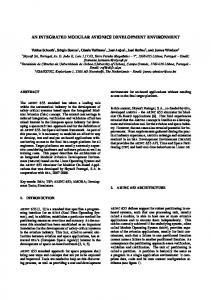
The hardware mapping problem. DIMA hardware with mapped functions needs to be mapped to available installation locations restricted by installation resources, like slots, and peripherals.
The complete binary problem is built again by the concatenation of constraint matrix.
Hardware Mapping
A similar problem is the mapping of devices to installation locations. The hardware mapping problem is depicted in Fig. 2. Hardware and installation topology are known. Software is already mapped to the hardware. Installation locations are suitable spaces to assign devices. However, device installation might require installation resources, e.g. volume, slots, and cooling capacity, which must be available in a sufficient quantity. In addition, peripherals
(15)
ܣመோ ܣመ ൌ � ቆ መ ቇ ܣ௦௧ ܣመ ൌ ܣመ௦
If a solution exists solving this binary problem with ݂ ൌ ͳ results in a valid device mapping. Advanced cost functions are mass and operational interruption cost as shown in section three.
3
Deutscher Luft- und Raumfahrtkongress 2012
2.3.
mass of a peripheral cable is calculated as the length of the cable times the weight per length, which is a property of the used cable type. Software mapping of tasks requiring peripherals directly influences the peripheral wire mass, since the peripheral connection wire must be routed between the peripherals installation location and the installation location of the DIMA device the task is mapped to. Each assignment possibility is, therefore, weighted with the mass of the cable ݉ that would be needed for this assignment.
Solving
Binary Programming problems belong to the class of NPcomplete problems [16], i.e. the number of calculations necessary for solving the problem is almost proportional to the number of all theoretic solutions. In general, those problems can either be solved globally optimal by testing all solutions, which results in long up to infeasible calculation times or heuristically. Heuristics, in general, do not result in the globally optimum, but find “good-enough” solutions. Often the quality of the result is tunable by the calculation time spend. A trade-off between both domains is non-deterministic global search. Such algorithms leverage problem properties to achieve calculation times that are on average far below that of global search. The worst case calculation time is, however, not reduced. Benchmarks for both mapping problems showed that the most common branch-and-bound approach still leads to infeasible calculation times for realistic problem sizes. More advanced branch-and-cut algorithms showed feasible calculation times [17]. The latter is, therefore, proposed for solving both mapping problems.
(16)
݂ெ ൌ ሺ݉ଵ ǡ ǥ ǡ ݉ேೣ ሻ
The cable routing is estimated as the shortest path through the cable route graph from the installation model. Task with no peripheral connection do not contribute to the cost vector. Hardware mapping influences peripheral cable mass in the same way. However, the movement of one device from one installation location to another changes the cable length of all peripherals connected to task on that device. A devise assignment possibility is, therefore, weighted with the accumulated mass of all affected cables.
3. METHODS AND MATERIALS The proposed approach is demonstrated by optimizing manually mapped reference architecture subject to different quality objectives. This section describes the optimization implementation and environment, as well as the used quality measures, the reference architecture and the experiment’s setup.
3.1.
Environment
Input and output for optimization are stored in a custom domain model for DIMA architectures. This model is edited and evaluated within the Eclipse-based modeling environment for DIMA architectures, called optDIMA [15, 18]. Within the TUHH software tool optDIMA the optimization algorithm, the objective, and the objects to optimize are selected. Optimization inputs are automatically derived from the model and transformed into the corresponding binary problem matrixes. Information extraction and problem matrix creation takes place in MATLAB because of the high number of involved mathematical operations. Model data is exchange between optDIMA and MATLAB in XMI format [19]. The binary programming problem is solved using the branchand-cut solver of the CPLEX optimization environment [20]. Result interpretation and back-transformation to the DIMA architecture model takes place in MATLAB before the final result is visible in optDIMA. Fig. 3 depicts the full tool chain.
FIG 3.
Device mass is the accumulated mass of all DIMA devices of the architecture. The mass of each device is defined by the device type, which is associated with a constant mass value. The only possibility to change device mass by mappings to create empty and, therefore, unused devices during software mapping. Mapping devices always results in the same device mass. Since device mass is not defined by a single task assignment possibility, the solution vector and all matrices of binary problem the need to be extended by ܰ assistant variables [21] representing whether a device is used or not. The cost ݂ெ vector for those variables is assigned to the mass of a single device ݉ .
All mapping optimizations were carried out on an Intel Xeon E31270 at 3.4 GHz with 8 GB RAM running Windows 7. MATLAB Version 2011b in combination with CPLEX 12.4 was used.
3.2.
Optimization tool chain. Architectures are developed, validated, and evaluated in optDIMA. MATLAB is used for forward and backward transformation between model elements and binary problem. CPLEX solves the given problem.
Quality Measures
Four quality measures are used to compare optimization results and the reference architecture. In addition, all measures are used as optimization objectives for the software mapping optimization and two are used for hardware mapping optimization. Peripheral wire mass is a major contributor to the overall mass of an avionic system. It comprises the mass of all cables that connect peripherals to DIMA devices. The
(17)
4
݂ெ ൌ ሺͲǡ ǥ ǡͲ ǡ ݉భ ǡ ǥ ǡ ݉ಿ ሻǤ ᇣᇤᇥ ଵǥேೣ
ವ
Deutscher Luft- und Raumfahrtkongress 2012
Mass is the sum of peripheral wire mass and device mass. It is, therefore, the trade-off between using less devices and accepting longer cables. Since device mass is only changeable trough software mapping, mass objective is also only available for task mapping optimization. The corresponding cost vector ݂ெ for the binary problem is built by combining the cost vector for peripheral wire mass ݂ெ with the last part of the device mass cost vector ݂ெ .
platform. Fig. 4 shows the reference architecture, and Tab. 1 summarizes most important quantities. The selected platform is composed of Core Processing Modules (CPM) and Remote Data Concentrators (RDC), which are connected over a redundant AFDX network. CPMs are pure computing modules. RDCs provided I/O connectors for peripherals and connect them to the AFDX network. Switches connect several devices on the AFDX network. Switches and RDCs are distributed modules, and can be installed in four installation locations. Those are the aircraft’s nose, the avionics bay (below the cockpit), the middle and the tail. CPMs can be installed in the avionics bay only. Two types of CPM and RDC cope with dissimilarity requirements. The processing powers of the CPM types differ and both RDC types have a different number and types of I/O interfaces. In summary, two CPMs of each type, eight RDCs of type one and two of type two are installed (s. Fig. 4(c)). In addition, 40 peripherals are installed in 15 additional installation locations all over the aircraft connected by cable routes of known length (s. Fig 3(d)).
݂ெ ൌ ሺ݂ெ ǡ ݂ெಿೣ శభǥಿೣశಿ ሻ
(18)
ವ
Operational interruption costs (OIC) ܿ ைூ are the costs resulting from flight delay or cancelation because of unscheduled maintenance operations on the avionics system, e.g. repair or replacement of DIMA devices. The is the sum of costs introduced by OIC for one device ܿைூ or a delay ܥா . cancelation ܥோ ܿ ைூ ൌ � ܿா ܿோ
(19)
ୀଵ
Four related systems have been selected from the oxygen, pressure, air, and air-conditioning domain1. All four systems (s. Fig. 4(a)) are duplex systems, i.e. each system has a fully redundant counterpart. Both counterparts need to be segregated. In addition, an intersystem constrained requiring dissimilar device types is enforced between SYSTEM 2 and SYSTEM 4. As depicted exemplarily in Fig. 4(b) all systems have a main controller task and several I/O task for each connected peripheral. The controller task requires computing resources. The I/O tasks require different combinations of ten I/O types. In addition, the criticality, i.e. the MEL level, of the systems was set to NOGO for SYSTEM 3 and 4, GOIF for system 1 and GO for SYSTEM 2.
Whether a flight is delayed or canceled is decided on the Minimum Equipment List (MEL) code of the device and the time needed for repair [3]. Therefore, ܿ ா and ܿ ோ are functions of the MEL level, the repair time, and the module reliability, i.e. critical functions mapped to reliable modules in fast accessible installation locations minimizes OIC. Here three MEL levels are defined. GO means the flight can continue with the failed equipment. GOIF means the flight can continue if certain conditions hold. NOGO means the failed equipment must be repaired before takeoff. In case of DIMA the MEL level of a DIMA device is defined by the most critical function mapped to the device. MEL levels are defined for task and task groups in the domain model. The repair time is composed of the time needed to access the device and a fixed amount of time needed for repairing a device. The latter is a property of the device type. The access time is specified for each installation location. For instance devices in the avionics bay can be replaced faster than the devices installed in the tail. Since OIC is not influenced by the individual assignments but a combination of assignments, the cost vector for OIC ݂ைூ for the task assignment problem� equals zero for each assignment and is extended by ܰ � ൈ ͵ additional variables. Each of the additional entries contains the OIC that the device would have if it has a certain MEL level.
An initial mapping was created manually. Tasks have been placed on modules closest to the belonging peripheral, while considering the segregation constraints. The I/O resources per RDC were determined by assigning each RDC type the I/O types used by the peripherals connected to this RDC. The number of I/Os of each type was set to the maximum number of this I/O type used on any RDC instance.
ሺ ܮܧܯൌ ͳሻ�ǡ �ܿைூ ݂ைூ ൌ � ሺͲǡ ǥ ǡͲ ǡ ܿைூ ሺܮܧܯ ᇣᇤᇥ భ భ ଵǥேೣ
(20) ൌ
ሺܮܧܯ ʹሻǡ �ܿைூ భ
58
Devices
14
Peripherals
40
Installation Locations
19 (4 for DIMA devices)
ሺ ܮܧܯൌ ͵ሻሻ ൌ �͵ሻǡ ǥ ǡ ܿைூ ಿ ವ
Resource Types
For the device mapping problem the MEL level is known for every device. Therefore, the cost vector contains at each assignment possibility the OIC that the device would cause if assigned to a certain installation location.
3.3.
Tasks
Possible Task Mappings Possible Device Mappings
Reference Architecture
10 1008 ֜ ʹଵ଼ Solutions 194 ฺ ʹଵଽସ Solutions
TAB 1. Quantities of reference architecture. Possible mapping entries denote the number of theoretic solutions for the optimization problem.
Validation and benchmarking of the proposed optimization approach is carried out with a DIMA reference architecture, which is an excerpt of and airplane’s full architecture. However, the reference architecture is a fully functional mapped DIMA architecture based on an IMA2G-
1
5
System names have been obscured
Deutscher Luft- und Raumfahrtkongress 2012
(a) Software of four duplex aircraft systems. Tasks (light blue) of each system instance are grouped in task groups (dark blue). Dashed lines denote segregation constraints. Purple boxes and lines are peripheral components required by tasks.
(b) Inside view of SYSTEM 1 A. TASK 0 is the main controller task. Other tasks are I/O tasks connected to peripherals. Arrows denote directed message flow (signals). Each task has certain resource requirements and needs to be mapped to DIMA modules.
(c) DIMA hardware topology consisting of four CPMs ten RDC connected over a redundant AFDX network with eight switches
(d) Aircraft anatomy for avionics installation. Boxes denote installation locations, which can provide installation resources (screws), and are connected with cable routes and joints. Installation locations providing resources for DIMA devices are NOSE, AVIONICS BAY, MIDDLE, TAIL.
FIG 4.
Reference architecture for optimization experiments. Depicted are systems software (a), a detailed view on SYSTEM 1 A, the DIMA hardware topology (c), and the aircrafts installation structure (d).
6
Deutscher Luft- und Raumfahrtkongress 2012
3.4.
peripheral wire and device mass. The highest reduction down to 74% is perceived by optimizing for this objective. Since the device mass of this optimization equals the device mass of the device mass optimization, this reveals a non-unique solution space for the latter. The highest increase up to 111% is archived optimizing device assignment for OIC.
Optimization Experiments
The proposed optimization approaches were used to carry out six optimization experiments based on the reference architecture. Four task mapping optimizations were carried out with the objectives -
peripheral wire mass, device mass, mass, and operational interruption cost (OIC).
The most significant improvement of 48% is made in OIC as depicted in Fig 5(d). The latter is archived by task assignment optimization subject to OIC, by grouping NOGO tasks on modules in easily accessible installation locations. For device assignment a reduction of 39% is archived. Except the optimization for peripheral wire mass the OIC of all optimized architectures is lower or equal than that of the reference architecture. Besides the distribution of tasks, the lower number of used devices in experiment 2 and 3 majorly caused the reduction.
In addition, two device mapping optimizations were carried with the objectives -
peripheral wire mass and operational interruption cost (OIC).
The resulting architectures were validated in optDIMA for resource exceeding and constraint violations. In addition, the all four quality measures, i.e. peripheral wire mass, device mass, mass, and operational interruption cost were calculated for each optimized architecture and the reference architecture. Based on this result the six optimized architectures were compared to the mapping of the reference architecture. Moreover, calculation times for optimizations were recorded.
5. DISCUSSION The proposed optimization approaches resulted in valid architectures in all optimization experiments. No violation of resource or secondary restrictions was perceived. Moreover, algorithm run-times do not prevent practical application. Especially the short run-time of the solver is surprising. It seems that the special problem structure of both mappings helps to solve the generally hard to solve binary programming problem unexpectedly fast. It can be stated, therefore, that both approaches are at least capable of identifying valid mappings, which, if doing it manually, can be a difficult task in reality. Almost instantly finding valid mappings enables rapid prototyping of DIMA architectures in the early aircraft development phase. Moreover, the DIMA designers can react quickly to system or hardware changes with new adapted mappings. This improves early validation, evaluation and problem identification skills of the DIMA designer.
4. RESULTS All six optimization experiments resulted in valid mappings. The run-time for task mapping was between 32s and 36s. Device mapping took 45s. In both cases the calculation time splits in approximately 64% preprocessing and problem building, 2% solving, 28% post processing. Fig. 5 shows the evaluation of the six optimization experiments. It depicts how the value of each of the four quality measures for each optimization experiment changes relative to the value of the manually mapped reference architecture.
The handling of optimization objectives, in addition, reveals prior unknown potential for improvements in three out of four considered quality measures. Most notably is the reduction of the number of used devices, which is beneficial for all objectives. The task mapping optimization showed more potential than device mapping. Naturally, the latter problem occurs seldom during DIMA design. However, the results also show that improving one objective might downgrades another, i.e. some quality measures are contradictory. Indeed, the optimization for a single objective could lead to unpredictable bad performance in non-optimized objectives, although better solutions might be available without changing the primary objective. A solution for this might be a multi-objective optimization approach. Nevertheless, single-objective optimization can at least be used to explore the solution space and to justify architectures. For instance, it can answer questions like “Is this the best we can do?” and “Is there any architecture with lower cable mass?”. Those can be of major importance in economic decisions. Answering “What-if”-questions is enabled by the proposed global optimal optimization algorithm. Optimization results of a heuristic algorithm would have less significance.
Fig. 5(a) shows the change in the peripheral wire mass. Notably, none of optimizations resulted in a lower cable mass than that of the reference architecture. However, both optimizations subject to the peripheral wire mass resulted in an equivalent wire mass. This validates the assumption that the chosen manual mapping process results in the shortest possible cable length. The highest increase of peripheral wire mass is perceived when optimizing for OIC. The OIC increased to 186% after software mapping and to 227% after hardware mapping. Fig. 5(b) quantifies the change in device mass. By concept no optimization resulted in an increased device mass, since all devices are allocated in the reference architecture. Moreover, device assignment optimization cannot change the device mass. However, all task assignment optimizations resulted in a lower number of used devices, which is remarkable, since the number of resource per module type is exactly adapted to the reference mapping. This hints to a not optimal decision on the number of needed devices during the manual design or to additional requirements not covered in this study. Optimization for device mass and cumulative mass resulted both in using only nine of the 14 device used in the reference architecture.
Overall it has been demonstrated that both presented approaches can significantly speed up the DIMA architecture definition process, and, moreover, help developing more optimal architectures subject to the presented objectives on aircraft level, which is today
Fig. 5(c) depicts the relative change of combined
7
Deutscher Luft- und Raumfahrtkongress 2012
hardly possible manually. The ability to be applied on full architectures or selected sub-parts widens the field of application. However, the tested architecture is a ~5% cutout of a full airplane avionics architecture. It needs to be verified that acceptable run-times and optimization benefits persist on global aircraft-level.
(d) Relative operational interruption cost (OIC)
FIG 5.
(a) Relative peripheral wire mass (PM)
Results of optimization experiments for software assignment (TA) and hardware assignment (DA). Evaluated with the quality measures peripheral wire mass (PM), device mass (DM), mass (M), and operational interruption cost (OIC). Dashed line denotes the result of the manually created reference architecture. Experiment numbers: 1=TA:PM, 2=TA:DM, 3=TA:M, 4=TA:OIC, 5=DA:PM, 6=DA:OIC.
6. CONCLUSION Mapping of system function software on DIMA hardware, as well as mapping devices is a difficult task since mapping is restricted by available resources and constraints, like segregation, resulting from safety and performance requirements. For both, hardware and software mapping, an approach was presented, which transforms the problem in a binary programming problem and solves it globally optimal with a branch-and-cut algorithm. In addition, both approaches allow the inclusion of a quality objective, which enables automatic calculation of valid architectures optimal to the objective. Algorithm input data is automatically derived from a DIMA system domain model. Feasibility of both approaches was demonstrated with manually mapped reference architecture. The reference architecture representing four duplex-redundant aircraft system has been optimized for task and device mapping in six experiments. For the objectives peripheral wire mass, device mass, mass and operational interruption cost (OIC) mappings with 26% lower mass and 45 % lower OIC were found. Calculation times below 1 minute enable practical usage. An additional result is, however, that not all objectives can be optimized at the same time. In summary, the presented approaches enable fast automated creation of valid architecture and help to identify optimization potential during the DIMA architecture design phase. Therefore, both approaches can speed up DIMA development and help to leverage the full potential of new avionics concepts, which is manually hardly possible for the avionics systems of future aircrafts, which are constantly rising in size and complexity.
(b) Relative device mass (DM)
The next step is to validate these results on larger architectures up to full-aircraft DIMA architectures. Further
(d) Relative cumulative mass (M)
8
Deutscher Luft- und Raumfahrtkongress 2012
research is necessary in the fields of multi-objective optimization enabling a trade-off optimization between different quality objectives. Moreover, combined optimization of task and device mapping or the automated optimization of device types might increase the optimization potential.
IEEE/AIAA, pages 1–12, October 2006. [15] B. Annighöfer, E. Kleemann, and F. Thielecke. Modelbased development of integrated modular avionics architectures on aircraft-level. In Deutscher Luft- und Raumfahrtkongress, Bremen, September 2011. DGLR. [16] Pierluigi Crescenzi and Viggo Kann. A compendium of NP optimization problems. http://www.nada.kth.se/~viggo/wwwcompendium/. [17] W. Cook and M. Hartmann. On the complexity of branch and cut methods for the traveling salesman problem. In Polyhedral combinatorics: proceedings of a DIMACS workshop: June 12-16, 1989, volume 1, page 75. Amer Mathematical Society, 1990. [18] Björn Annighöfer. optdima - optimization and planning tools for distributed modular avionics. http://www.fst.tu-harburg.de/optdima/, July 2012. [19] Object Management Group (OMG). Xml metadata interchange specification. http://www.omg.org/spec/XMI/, July 2005. [20] IBM. ILOG CPLEX Optimizer. http://www01.ibm.com/software/integration/optimization/cplexoptimizer/. [21] B. A. McCarl and T. H. Spreen. Applied Mathematical Programming Using Algebraic Systems. Dept. of Agr. Econ. Texas A&M University, 1996.
7. REFERENCES [1] P.J. Prisaznuk. Integrated modular avionics. In Aerospace and Electronics Conference, 1992. NAECON 1992., Proceedings of the IEEE 1992 National, pages 39–45 vol.1, May 1992. [2] R. Fuchsen. Preparing the next generation of ima: A new technology for the scarlett program. In Digital Avionics Systems Conference, 2009. DASC ’09. IEEE/AIAA 28th, pages 7.B.5–1 –7.B.5–8, October 2009. [3] K. Neumann, E. Kleemann, R. Reichel, and M. Lehmann. Quantitative evaluation criteria for modern avionic system architectures. In Deutscher Luft- und Raumfahrtkongress, Darmstadt, September 2008. DGLR. [4] V.M. Lo. Heuristic algorithms for task assignment in distributed systems. Computers, IEEE Transactions on, 37(11):1384 –1397, nov 1988. [5] Shahid H. Bokhari. Assignment Problems in Parallel and Distributed Computing. Kluwer, 1987. [6] M. Kafil and I. Ahmad. Optimal task assignment in heterogeneous computing systems. In Heterogeneous Computing Workshop, 1997. (HCW ’97) Proceedings., Sixth, pages 135 –146, 1 1997. [7] M. Sghairi, A. de Bonneval, Y. Crouzet, J.-J. Aubert, and P. Brot. Architecture optimization based on incremental approach for airplane digital distributed flight control system. In World Congress on Engineering and Computer Science 2008, WCECS ’08. Advances in Electrical and Electronics Engineering - IAENG Special Edition of the, pages 13–20, Oct. 2008. [8] Laurent Sagaspe, Gerard Bel, Pierre Bieber, Frederic Boniol, and Charles Castel. Safe allocation of avionics shared resources. High-Assurance Systems Engineering, IEEE International Symposium on, 0:25– 33, 2005. [9] Laurent Sagaspe and Pierre Bieber. Constraint-based design and allocation of shared avionics resources. In 26th AIAA-IEEE Digital Avionics Systems Conference, Dallas, 2007. [10] Horst Salzwedel, Nils Fischer, and Gunar Schorcht. Moving design automation of networked systems to early vehicle level design stages. In SAE World Congress, Detroit, 2009. [11] Frank Lohse, Volker Zerbe, and Thomas Luetzelberger. Architecture analysis and optimization of reconfigurable, complex systems. In Intelligent Engineering Systems (INES), 2010 14th International Conference on, pages 221 –225, may 2010. [12] Uwe Salomon and Reinhard Reichel. Automatic safety computation for IMA systems. In Digital Avionics Systems Conference (DASC), 2011 IEEE/AIAA 30th, pages 7C3–1 –7C3–9, oct. 2011. [13] D. Mazuk. IMA resource allocation process. In Digital Avionics Systems Conference, 2008. DASC 2008. IEEE/AIAA 27th, pages 1.B.2–1 –1.B.2–6, oct. 2008. [14] C.B. Watkins. Integrated modular avionics: Managing the allocation of shared intersystem resources. In 25th Digital Avionics Systems Conference, 2006
9