are integers such that, k = klk2, and as before k 5 T + 1). The general expression for the number of memory banks required, the total memory size and the latency ...
SURVIVOR SEQUENCE MEMORY MANAGEMENT IN VITERBI DECODERS Gennady Feygin and P. Glenn Gulak Department of Electrical Engineering University of Toronto
Canada ABSTRACT
I
In a Viterbi Decoder, there are two known memory organization techniques for the storage of survivor sequences from which the decoded information sequence is retrieved. The register erchange method is the simplest conceptually but suffers from the disadvantage that every bit in the memory must be read and rewritten for each information bit decoded. The alternative is the traceback method where the interpretation of the symbols as pointers removes the necessity to move data in the memory. Thi#paper extends previously known traceback approaches and describes a new one-pointer traceback algorithm for survivor sequence memory management that is particularly well-suited to a VLSI implementation. Memory size, latency and implementational complexity of the survivor sequence management are analyzed for both uniprocessor and multiprocessor realiza tions of Viterbi Decoders.
1
INTRODUCTION
There are two known methods for the storage of survivor sequences from which the decoded sequence is retrieved. The Register Ezchange (RE) method is the simplest conceptually and a commonly used technique [l][2]. Because of the large power consumption and large area required in VLSI implementations of the R E method, the Tmceback (TB) method has been receiving more attention lately in’the design of the large constraint length, high performance Viterbi Decoders. Recently, [3] have described the details of their proposed implementation of T B in a large multiprocessor Viterbi Decoder. An actual implementation of T B was reported in [4]. In this paper we describe two T B methods which are generalizations of the approaches introduced in [4] and [3]. We also introduce a third alternative implementation of TB, which offers certain advantages over the other two T B apprpaches. The relative merits of the various approaches t o T B are compared and contrasted with the RE method. This paper is organized as follows: In Section 2 we give a general description of a Traceback method, that relies on backpropagation of pointers through the memory containing the path information. Sections 3.1, 3.2 3.3 and 3.4 describe four alternative implementations of a Traceback method, with extensions of two previously known implementations of Traceback, as well as two brand new implementation, one of which we call a One-Pointer Tmceback Algorithm and the other a Hybrid Tmceback Algorithm. Four alternative implementations are compared with each other and with Register Exchange
method in Section 4.1 In Section 4 we also concern ourselves with some practical details of Traceback decoder, such as trading off the latency against the number of memory modules into which the Traceback memory must be subdivided. Finally, Section 5 summarizes the main results of this paper.
2
TRACEBACK METHOD
We will omit the details of the Register Exchange method, which is widely used and is straightforward. Details of the RE method can be found in [5]. The Traceback method stores path information in the form of an array of recursive pointers, and was originally proposed by [SI. Unfortunately, direct implementation of the Traceback method proposed in [6] is impossible, since i t treats memory as infinite in size, while any actual implementation contains only a finite memory. It is advantageous t o think of traceback memory as organized in a two-dimensional structure, with rows and columns. The number of rows is equal t o the number of states N = 2”. Each column stores the results of N comparisons corresponding to a Trellisstage-Time. Since the stream of symbols is, in general, semi-infinite, storage locations are periodically reused. There are three types of operations performed inside a T B decoder: Traceback read (tb) - This is one of the two read operations and consists of reading a bit and interpreting this bit in conjunction with the present state number as a pointer that indicates the previous state number (i.e. state number of the predecessor). Pointer values from this o p e r a tion are not output as decoded values, instead they are used t o ensure that all paths have converged with some high probability, so that actual decoding may take place. The traceback operation is usually run to a predetermined depth, T , before being used t o initiate the decode read operation (described next).
Decode read (dc) - This operation proceeds in exactly the same fashion as the traceback operation, but operates on older data, with the state number of the first decode read in a memory bank being determined by the previously completed traceback. Pointer values from this operation are the decoded values and are sent to the bit-order reversing circuit. A decode read can serve as a dual decode and traceback read, this allows us t o decode read multiple columns using one traceback read operation of T columns.
CH 3006-4/91/0000 - 2967 $1.00 0 IEEE
Writing n e w data (wr) - The decisions made by the ACS are written into locations corresponding to the states. The write pointer advances forward as ACS operations move from one stage t o the next in the trellis, and data are written to locations just freed by the decode read operation. For every set of column write operations (N bits wide) , an auemge of one decode read must be performed. The overhead
of 2’-column traceback read can be spread over one or more column decode read operations, resulting in k > 1 read operations, this includes both decode read operations and traceback read operations.
3 3.1
E.
3.3
FOUR TRACEBACK ALGORITHMS
The le-Pointer Even Algorithms
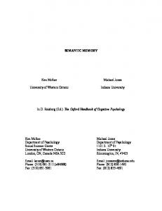
The k-Pointer Even Algorithm is a generalization of the implementation of the Traceback Algorithm implemented in [4]. This generalization was also independently discovered by [7]. Figure 1 illustrates how, for a particular value k = 3, read and write operations proceed in parallel in the memory, which is divided into bahks. The memory is divided into 2k memory banks, each of size T / ( k - 1) columns, as shown in Figure 1. Each read pointer is used to perform the Traceback operation in k - 1 memory banks, and the Decode read in one memory bank. Every T Trellisstage-Times, a new traceback front is started from the fixed state such as all zeroes (or the state with the best path metric if best state decoding [8] is used), and a new decode front is started a t a location determined by the traceback pointer derived in the previous Trellisstage-Time. Since the Traceback depth T must be achieved before decoding can be performed, the number of columns in k - l memory banks must be greater than or equal to T. This permits us t o compute the total amount of memory and latency of the k-Pointer Even Algorithm. Each memory bank is columns long, and there are a total of 2k mpmory banks, for a total of columns. The latency of the k-Pointer Even Algorithm is the time delay between the writing of the particular column and the time that column i s subjected to decode read. Depending on the position of the column inside the memory bank, the delay can w y from for the first column in a memory bank, to for the last column in a memory bank. The decoded bits are generated in a reverse order, thus a scheme is required for reversing the ordering of the decoded bits. A simple two-stack (LIFO) structure is sufficient to perform the bit order reversal. Each stack must be in depth. During the decoding of one memory bank, decode$ bits are pushed on one stack, while the bits stored on the other stack are popped. Upon completion of the decoding of a given memory bank, stacks switch from pushing t o popping and vice versa. In addition to bit order reversal, two-stack structure equalizes the latencies of all decoded bits. The overall latency of the k-Pointer Even Algorithm, including the two-stack structure, is
8
E
&
E.
3.2
w.
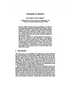
for a total length of A two-stack LIFO structure is also required to perform bit order reversal. Latency of the k-Pointer Odd Algorithms (including the two-stack structure) is As indicated in Figure 2, the decode pointer and the write pointer always point to the same column in the memory, although the decode pointer will be used to read only one memory location, while the write pointer will be used to sequentially update memory locations corresponding to all states in a given trellis stage (i.e. all 2” bits). It is necessary to perform decoding before new data can be written, otherwise the contents of the memory being used to generate the decoded information bit may be overwritten before it is read.
The k-Pointer Odd Algorithms
The One-Pointer Algorithms
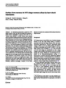
The One-Pointer Algorithm [9] differs significantly from the kPointer Odd and Even Algorithms. Instead of utilizing k read pointers t o perform the required k reads for every column write operation, we chose to use a single read pointer, but accelerate read operations, so that every time the write counter advances by one column, 6 column reads occur. This acceleration of read operations is made possible by the fact that among the three operations, writing new data, traceback read and decode read, writing new data is by far the most time consuming. This observation is particularly important as 2“ bits are written every Trellisstage-Time, as opposed to only k bits being read. The One-Pointer Algorithm (with k = 3) is illustrated in Figure 3. Only k+ 1 memory banks, each columns long, are required,
&
for a total of columns. A single read pointer produces the decoded bits in bursts. While reading k memory banks, no decoded data is available from the first k - 1 memory banks. During the decode read operation in the k-th memory bank, decoded bits are generated at a rate of k per Trellisstage-Time. Fortunately, the two-stack structure discussed above can perform both bit order reversal and burst elimination a t the same time. The latency of the One-Pointer Algorithm, including two-stack structure, is
&.
3.4
The Hybrid Algorithms
A hybrid approach to TB, which combines some features of the k-Pointer Algorithm (either Even or Odd) and a OnePointer Algorithm is also possible, with k column reads per Trellisstage-Time are performed using k1 read pointers, each advancing at a rate of k2 columns per Trellisstage-Time (kl,k2 are integers such that, k = klk2, and as before k 5 T 1). The general expression for the number of memory banks required, the total memory size and the latency are computed as follows: each memory bank is columns long, and the number of memory banks is kl(k2 1) for the hybrid of k-Pointer Even Algorithm and One-Pointer Algorithm (k1(k2 1) - 1) for the hybrid of k-Pointer 0 dd A1 orithm and One-Pointer Algorithm. The latency is k( l k l k ~ ~ ~for l T k-Pointer Odd hybrid as well as for k-Pointer Even hybrid . When either kl or k2 is set to one, the expressions above agree with the expressions for the One-Pointer or k-Pointer Algorithms respectively.
The k-Pointer Odd Algorithm is a generalization of the implementation of the Traceback Algorithm proposed in [3]. Figure 2 is an illustration of operation of a 3-Pointer Odd Algorithm. Altogether, there are 2k - l memory banks, each of length
A, 2968
+
& +
+
4.1
of controls). In our discussions we have assumed that k is an integer. It is possible to modify any one of the three T B methods t o work with rational k, in other words k = ,: where m, n are integers. This is of limited practical value, since memory becomea fragmented into a large number of memory banks and control becomes unnecessarily complex.
DISCUSSION
4
Comparative Advantages
The hybrid approach, though conceptually interesting, offers no significant advantages over the One-Pointer Traceback Algorithm. Latency, total memory requirements and the number of memory banks for a hybrid approach with k l k 2 = k will be higher than for the One-Pointer approach with k column reads per column write ratio Furthermore, read pointer controls in the case of hybrid approach will be more complex than in the case of OnePointer approach, since circuitry must keep track of k2 pointers advancing at a rate of k2 column read operations per column write operation. It should be pointed out that in [7] authors have independently derived the Hybrid Traceback approach (Even case only) using a slightly different approach. The k-Pointer Odd Algorithm offers no significant advantages over either h-Pointer Even or OnePointer Algorithms. In k-Pointer Odd method, bi-directional column counters are required for both write and read pointers, since the direction of the memory bank accesses alternates, as illustrated in Figure 2. Furthermore, decode read and write operations share the same set of memory l o c a ~ o n s .It is necessary t o “stall” write operations to allow the decode read operation to complete before the information bits in the set get overwritten. Thus writing cannot proceed at a uniform pace, and Trellisstage-Time must be divided into 2” 1 intervals; the design of a counter for this is difficult. The k-Pointer Even Algorithm is significantly better. The counter design is very simple, with each read counter and the write counter advancing by exactly one column every Trel1isStage-Time. The One-Pointer Algorithm is the best amongst the known T B methods. It requires approxinately half as much memory as either the of k-Pointer Even or Odd Algorithms. The latency is similarly reduced by a factor of two. In addition, the number of memory modules required is also half as large as that required by the k-Pointer Algorithms. The only disadvantage of the One-Pointer Algorithm is the need t o provide separate column counters for the write operations and for the read operations, since the read counter advances by k columns for every one column advance of the write pointer. If k is selected to be a power of two, say 2*, then the read counter can be implemented simply by using the b most significant bits of the write pow counter as b least significant bits of the read counter. In a fully parallel system (i.e. all 2” decisions of a given stage are computed and written simultaneously on the same clock cycle), the k-Pointer Even Algorithm, with only a single read operation per pointer per clock cycle, is better than the One-Pointer Algorithm that requires k read operations per pointer per clock cycle. The characteristics of various Traceback approaches and Register Exchange approach are summarized in Tables 1 and 2. In order to significantly boost the throughput of Viterbi Decoders, researchers are increasingly turning to use of multiple processing units. Although full details cannot be given in this short paper, we must note that the advantages of the T B method over the RE method become even more pronounced when Survivor Sequence memory is distributed. Selection of the proper value of IC allows one to trade off the latency against the number of memory banks (i.e. complexity
5
.
SUMMARY AND CONCLUSIONS
This paper has presented several new algorithms for traceback memory management in Viterbi Decoders. For a highspeed, large constraint length VD the Traceback algorithm is advantageous as compared to the Register Exchange method. T B method is superior because of the lower bandwidth requirements (lower power dissipation). The TB method is particularly suitable for use in a multiprocessor implementation of the VD with memory distributed among the processors; in a multiprocessor VD the T B method requires one to two orders of magnitude less area than the R E method. We have dkmonstrated a novel implementation of the Traceback Decoder, which is better than previously known implementations, with lower latency, lower total amount of memory required and fewer memory banks, resulting in simpler control circuitry. We have also demonstrated the possibility of reducing the latency of the decoder to as low as T 2 Trellisstage-Times a t the expense of an increase in complexity of the T B memory controller.
+
+
REFERENCES R. M. Orndorf et al. Viterbi Decoder VLSI Integrated Circuit for Bit E m r Correction. Rockwell International, Anaheim, California 92803,December 1981.
C. B. Shung et al. Implementation Issues for the Design of a Rate 8/10 Trellis Code for Partial Response Channels. In Third IEM Workshop on ECG, San Jose, California, September 1989. F. Pollara and 0. Collins. Memory Management in Traceback Viterbi Decoders. TDA Progress Report 42-99,Jet Propulsion Laboratory, Pasadena, California, November 1989. H. A. Bustamante et al. Stanford Telecom VLSI Design of a Convolutional Decoder. In IEEE Conference on Military Communications, volume 1, pages 171-178, Boston, Massachusetts, October 1989.
G. C. Clark and J. B. Cain. Error Correction Coding for Digital Communications, page 262. Plenum Press, 1981. C. M. Rader. Memory Management in a Viterbi Algorithm. IEEE “bansactions on Communications, 29:1399-1401,September 1981. R. Cypher and C. B. Shung. Generalized Trace Back Techniques for Survivor Memory Management in the Viterbi Algorithm. In Globecom, pages 1318-1322, Dec 1990. R. J. McEliece and I. M. Onyszchuk. Truncation Effects in Viterbi Decoding. In IEEE Conference on Military Communications, volume 1, pages 541-545, Boston, Massachusetts, October 1989. G. Feygin, P. G. Gulak, and F. Pollara. Survivor Sequence Memory Management in Viterbi Decoders. In Third
on ECC, San Jose, California, September 1989.
2%9
IEM
Workshop
i BANKO
BANKl
BANK2
BANK3
BANK4
BANK5
TLpbE
BANKO
BANKl
BANK2
BANK3
BANK4
0
N-1 0
N-1 0
N-1 0
t
Path of t h e decoder pointer (decodeAlale)
".'*Path of the traceback pointer (tracebackatate)
Figure 1. Survivor Sequence update in 3-Pointer Even Method
1~
:
~
~
N-1)
~
~
Figure 2. Survivor Sequence update in 3-Pointer Odd Method
BANKO
BANKl
BANK2
BANK3
Read Bandwidth Total
I
I
k
T x 2y
T x 2"+l
2"
+ k x 2"
Table 1. Bandwidth Requirements of Survivor Sequence Management Using Register Exchange and Traceback. II
II I Tracehack II Traceback -- - - - - - __. Method Register Exchange One-P [ t-P Even I k-P Odd ' Number of &T2' T x 2y E T 2 " I &T2" IeT2" 11 Memory cells 11 Duahort I Standard I Standard I Standard 11
Latency
-1 .'..*
Path 01 the decoder pointer (decode-late)
11
T
F+T
I
I
i% T f i T
Table 2. Memory Requirements and Latency of Survivor Sequence Management Using Register Exchange and Traceback.
Path of the tracebwk pointer (tracebackatate) Written add-compare-select decision. for N states (0 through N-1)
Figure 3. Survivor Sequence update in One-Pointer Method
2970
-
~