Proposed methods have been implemented by academic software for logic synthesis of au- ... Key words: control unit, decomposition, FSM, FPGA, synthesis.
U NIVERSITY OF Z IELONA G ÓRA FACULTY OF E LECTRICAL E NGINEERING , C OMPUTER S CIENCE AND T ELECOMMUNICATIONS
Synthesis of Finite State Machines for Programmable Devices Based on Multi-Level Implementation Ph.D. Thesis Arkadiusz B UKOWIEC, M.Sc. Supervisor: Prof. Alexander BARKALOV, Ph.D. D.Sc.
Zielona Góra, June 2008
Acknowledgements The research has been partially financially supported by (Polish) Committee of Scientific Research in 2004-2006 (grant No. 3 T11C 046 26). The work was partially supported by the Integrated Regional Operational Programme (Measure 2.6: Regional innovation strategies and the transfer of knowledge) co-financed from the European Social Fund in 2005-2007.
Abstract New architectures of FPGA devices combine different type of logic elements like look-up tables, flip-flops and memory blocks. But standard synthesis methods utilize only look-up tables and flip-flops and it makes that device utilization is not optimal one. Methods of synthesis and implementation of Mealy finite state machines into Field Programmable Devices there are presented in this work. Proposed methods of synthesis are dedicated into developed multi-level structures of digital circuits of finite state machines. Architectures of designed structures are based on existence of decoders as second-level circuits. Methods of synthesis are based on the multiple encoding. There is also proposed hardware implementation into an FPGA device of developed multi-level structures. The hardware implementation is based on an implementation with use of look-up tables and memory blocks together. It leads to better utilization of a device that standard methods gives. Proposed methods have been implemented by academic software for logic synthesis of automata. Conducted experiments shown that these methods are effective for FPGA devices. Key words: control unit, decomposition, FSM, FPGA, synthesis.
Table of Contents . . . . . . . . . . . . . . . . . . . . . . . . . . . . . . . . . .
1
List of Figures . . . . . . . . . . . . . . . . . . . . . . . . . . . . . . . . . . . .
3
List of Tables . . . . . . . . . . . . . . . . . . . . . . . . . . . . . . . . . . . . .
5
. . . . . . . . . . . . . . . . . . . . . . . . . . . . . . . . . . .
7
1.1
Thesis of the Work . . . . . . . . . . . . . . . . . . . . . . . . . . . . . .
8
1.2
Goals of the Work . . . . . . . . . . . . . . . . . . . . . . . . . . . . . . .
9
1.3
The Structure of the Work . . . . . . . . . . . . . . . . . . . . . . . . . .
9
Architecture and Applications of Field-Programmable Devices . . . . . . . .
11
2.1
Programmable Logic Devices . . . . . . . . . . . . . . . . . . . . . . . . .
12
2.2
Field Programmable Gate Arrays . . . . . . . . . . . . . . . . . . . . . . .
13
2.3
Designing with FPDs . . . . . . . . . . . . . . . . . . . . . . . . . . . . .
15
2.3.1
The design flow for FPDs . . . . . . . . . . . . . . . . . . . . . .
16
2.3.2
Functional decomposition for FPDs . . . . . . . . . . . . . . . . .
17
. . . . . . . . . . . . . . . . . . . . . . . . . . . . . .
20
3.1
Methods of Specification of FSMs . . . . . . . . . . . . . . . . . . . . . .
21
3.2
Realization of FSMs . . . . . . . . . . . . . . . . . . . . . . . . . . . . .
25
3.3
Decomposition of Circuit of FSM . . . . . . . . . . . . . . . . . . . . . .
29
3.3.1
Functional Decomposition for FPGAs . . . . . . . . . . . . . . . .
29
3.3.2
Realization of FSMs with ROM Memories . . . . . . . . . . . . .
31
3.3.3
Architectural Decomposition of FSMs . . . . . . . . . . . . . . . .
32
Multi-Level Structures of Mealy FSMs . . . . . . . . . . . . . . . . . . . . .
40
4.1
Multiple Encoding of Microinstructions . . . . . . . . . . . . . . . . . . .
40
4.2
Multiple Encoding of Internal States . . . . . . . . . . . . . . . . . . . . .
44
Table of Contents
1
2
3
4
Introduction
Finite State Machines
TABLE OF CONTENTS 4.2.1
Multiple Encoding of Internal States with Current States as a Partitioning Set . . . . . . . . . . . . . . . . . . . . . . . . . . . . . .
45
Multiple Encoding of Internal States with µIs as a Partitioning Set .
49
4.3
Multiple Encoding of Microinstructions and Internal States . . . . . . . . .
53
4.4
Shared Multiple Encoding of Microinstructions and Internal States . . . . .
56
4.5
Shared Multiple Encoding of µIs and Internal States with Common Decoder
62
Implementation into FPGAs . . . . . . . . . . . . . . . . . . . . . . . . . . .
66
5.1
Automata Synthesis System . . . . . . . . . . . . . . . . . . . . . . . . .
68
5.2
Behavioral Verification . . . . . . . . . . . . . . . . . . . . . . . . . . . .
72
5.3
Logic Synthesis . . . . . . . . . . . . . . . . . . . . . . . . . . . . . . . .
74
5.4
Implementation . . . . . . . . . . . . . . . . . . . . . . . . . . . . . . . .
83
Summary . . . . . . . . . . . . . . . . . . . . . . . . . . . . . . . . . . . . .
96
6.1
The confirmation of the thesis . . . . . . . . . . . . . . . . . . . . . . . .
96
6.2
Improvements and other applications . . . . . . . . . . . . . . . . . . . . .
97
A CD-ROM . . . . . . . . . . . . . . . . . . . . . . . . . . . . . . . . . . . . .
99
4.2.2
5
6
Bibliography . . . . . . . . . . . . . . . . . . . . . . . . . . . . . . . . . . . . . 101
-2-
List of Figures 1.1
The decomposition of a digital system . . . . . . . . . . . . . . . . . . . .
7
2.1
The classification of Field-Programmable Devices . . . . . . . . . . . . . .
11
2.2
The structure of a PAL device . . . . . . . . . . . . . . . . . . . . . . . .
12
2.3
the structure of a CPLD . . . . . . . . . . . . . . . . . . . . . . . . . . . .
13
2.4
The structure of an FPGA . . . . . . . . . . . . . . . . . . . . . . . . . . .
14
2.5
The structure of a CLB . . . . . . . . . . . . . . . . . . . . . . . . . . . .
14
2.6
The design flow for PLDs . . . . . . . . . . . . . . . . . . . . . . . . . . .
16
2.7
The design flow for FPGAs . . . . . . . . . . . . . . . . . . . . . . . . . .
16
2.8
The implementation of the function F on a PAL device . . . . . . . . . . .
18
2.9
The implementation of the function F on a FPGA device . . . . . . . . . .
19
3.1
The Mealy FSM S1 and its state diagram . . . . . . . . . . . . . . . . . . .
22
3.2
The marked flow-chart Γ1 of the Mealy FSM S1 . . . . . . . . . . . . . . .
23
3.3
The KISS2 description of the FSM S1 . . . . . . . . . . . . . . . . . . . .
25
3.4
The structural diagram of P Mealy FSM . . . . . . . . . . . . . . . . . . .
26
3.5
The scheme of the Curtis’ functional decomposition . . . . . . . . . . . . .
30
3.6
The scheme of the general functional decomposition . . . . . . . . . . . .
30
3.7
ROM-based realization of FSM . . . . . . . . . . . . . . . . . . . . . . . .
32
3.8
Structural diagrams of double-level Mealy FSMs . . . . . . . . . . . . . .
33
4.1
The structural diagram of PY0 Mealy FSMs . . . . . . . . . . . . . . . . .
41
4.2
The structural diagram of PA and PAY Mealy FSMs . . . . . . . . . . . . .
45
4.3
The structural diagram of PYY Mealy FSMs . . . . . . . . . . . . . . . . .
50
4.4
The structural diagram of PAY0 Mealy FSM . . . . . . . . . . . . . . . . .
54
4.5
The structural diagram of PAYS Mealy FSM . . . . . . . . . . . . . . . . .
56
4.6
The encoding of identifiers . . . . . . . . . . . . . . . . . . . . . . . . . .
60
4.7
The structural diagram of PAYSC Mealy FSM . . . . . . . . . . . . . . . .
63
LIST OF FIGURES
5.1
The design flow for FPGAs with use of multi-level structures . . . . . . . .
69
5.2
The top-level module of the Mealy FSM dk14 with the structure PAY0 . . .
69
5.3
The P module of the Mealy FSM dk14 with the structure PAY0 . . . . . . .
70
5.4
The RG module of Mealy FSM dk14 with the PAY0 structure . . . . . . . .
70
5.5
The module Y of the Mealy FSM dk14 with the structure PAY0 . . . . . . .
71
-4-
List of Tables 2.1
Classification of PLDs . . . . . . . . . . . . . . . . . . . . . . . . . . . .
13
2.2
Size of memory blocks in FPGAs . . . . . . . . . . . . . . . . . . . . . .
15
2.3
Typical modes of embedded memory blocks . . . . . . . . . . . . . . . . .
15
3.1
The state transition and output table of the FSM S1 . . . . . . . . . . . . .
24
3.2
The DST of the Mealy FSM S1 . . . . . . . . . . . . . . . . . . . . . . . .
29
3.3
The transformed DST of the PY Mealy FSM S1 . . . . . . . . . . . . . . .
35
3.4
The decoder table of the PY Mealy FSM S1 . . . . . . . . . . . . . . . . .
35
3.5
The transformed DST of the PD Mealy FSM S1 . . . . . . . . . . . . . . .
38
3.6
Decoders table of the PD Mealy FSM S1 . . . . . . . . . . . . . . . . . . .
38
4.1
The transformed DST of the PY0 Mealy FSM S1 . . . . . . . . . . . . . .
43
4.2
The decoder table of the PY0 Mealy FSM S1 . . . . . . . . . . . . . . . . .
44
4.3
The transformed DST of the PA Mealy FSM S1 . . . . . . . . . . . . . . .
48
4.4
The internal state code converter table of the PA Mealy FSM S1 . . . . . .
49
4.5
The transformed DST of the PYY Mealy FSM S1 . . . . . . . . . . . . . .
52
4.6
The internal state code converter table of the PYY Mealy FSM S1 . . . . .
53
4.7
The transformed DST of the PAY0 Mealy FSM S1 . . . . . . . . . . . . . .
55
4.8
The part of the DST of the Mealy FSM S2 . . . . . . . . . . . . . . . . . .
59
4.9
The part of the transformed DST of the Mealy FSM S2 . . . . . . . . . . .
61
4.10 The Part of the microoperations decoder table of the Mealy FSM S2 . . . .
61
4.11 Part of code converter table of Mealy FSM S2 . . . . . . . . . . . . . . . .
62
4.12 The part of the common decoder table of the Mealy FSM S2 . . . . . . . .
64
5.1
Schematic diagrams of multi-level Mealy FSMs . . . . . . . . . . . . . . .
66
5.2
The simulation of the Mealy FSM dk14 . . . . . . . . . . . . . . . . . . .
73
5.3
Results of the logic synthesis of benchmarks from the library LGSynth91 .
75
5.4
Results of the logic synthesis of random benchmarks . . . . . . . . . . . .
78
LIST OF TABLES
5.5
Average results of the logic synthesis of standard benchmarks . . . . . . . .
81
5.6
Average results of the logic synthesis of random benchmarks . . . . . . . .
81
5.7
Results of the implementation of benchmarks from the library LGSynth91 .
83
5.8
Results of the implementation of random benchmarks . . . . . . . . . . . .
90
5.9
Average results of the implementation of standard benchmarks . . . . . . .
93
5.10 Average results of the implementation of random benchmarks . . . . . . .
93
-6-
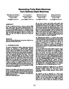
Chapter 1 Introduction The silicon product development grows very fast. This rapid evolution has resulted in appearance of very large scale integration (VLSI) chips and circuits. It makes possibility to implement a complex digital system in a single chip as a System-on-Programmable-Chip (SoPC) [Salcic: 1998; Jantsch: 2003]. Any digital system can be decomposed (Fig. 1.1) into a data path (DP) and a control unit (CU) [Barkalov: 1994b, 2003; Łuba: 2001]. Such decomposition gives opportunity for reuse
XE
D
XI
CU
DP YI
YE
R
XE – external control inputs XI – internal control signals D – data YE – external microinstruction YI – internal microinstruction R – results
Figure 1.1. The decomposition of a digital system
of early designed components or for use of intellectual property cores (IP Cores), that are available on the silicon market, for data processing. It means, that a data path can be built from already designed library of components and only a control unit have to be designed from the beginning. There are many modern methods of designing control units like statecharts [Drusinsky & Harel: 1989; Łabiak: 2005] or Petri Nets [Adamski: 2002; We¸grzyn: 2003]. But finite state machines (FSMs) [Curtis: 1962; Hopcroft & Ullman: 1979] are still one of the most popular way of specification of a algorithm of a control unit. Because a control unit is a part
1.1. Thesis of the Work
of almost any digital system, optimization of a designing and synthesis process of its digital circuit was a subject of many works from many years. In 80s there were many works oriented on implementation of FSMs with PLA structures [Papachristou: 1979; Dagless: 1983b]. In those days there was also started works on designing of state machines at former High School of Engineering in Zielona Góra (now University of Zielona Góra) by Prof. Marian Adamski [1980]. Together with development of silicon devices, methods of designing, synthesis and implementation of finite state machines have evolved also. Nowadays, FPGA devices are one of the most popular for realization of whole digital devices as SoPC. It creates new needs of fit a control unit into available hardware resources after implementation of a data patch. Because new FPGAs have different kind of logic elements it makes that not only reduction of hardware resources required for implementation of a finite state machine is a goal but also possibility to balanced use different types of resources.
1.1. Thesis of the Work Based on the description from previous sentences the Author undertook the research. The thesis of this research could be formed as: Multi-level architectural decomposition of a digital circuit of a finite state machine leads to rational usage of hardware elements of a programmable device which is used for implementation of a digital system. Architectural decomposition follows the physical parts of a system. It refers to the process by which a complex circuit is broken down into parts that are easier to implement. In case of finite state machine it split the combinational circuit into several circuits those together have the same function but each of them has different nature. The system after decomposition has a multi-level nature because data are processed serially and passed from one circuit to next one. By rational usage the Author understands: • a reduction of number of logic elements required for implementation of a finite state machine in comparison with standard methods of synthesis; • a balanced usage of different types of logic elements (such as logic blocks and memory blocks) available in programmable device; • a usage of available, not used, logic elements of a programmable device after implementation of other components of whole digital system. -8-
1.2. Goals of the Work
The first point means that designed method of synthesis should use less logic elements of one kind than standard methods of synthesis. Instead there could be also used logic elements of different kind. Balanced usage means that designed method of synthesis should use logic elements of different types in order to effective utilize whole programable device. The last point means that there should be developed a set of synthesis methods because different programable devices have different ratio of different types of logic elements and ratio of available logic elements could be also different for different data pathes.
1.2. Goals of the Work From this thesis the following theoretical goals appear: • a development of multi-level structures of a logic circuit of a finite state machine; • a development of synthesis methods of a finite state machine into designed multi-level structures; • a development of rules of hardware implementation of designed multi-level structures. The realization of these theoretical goals is a base for creation of Author’s system for logic synthesis of FSMs – the Automata Synthesis System (called in shortcut as the A♠S System or just the A♠S) [Bukowiec: 2008]. This system implements developed synthesis methods. There was assumed that the thesis will be proved by: • a comparison of simulation results of benchmarks synthesized with use of designed methods with results of behavioral simulations of these same benchmarks; • a comparison of results of implementations into an FPGA of benchmarks synthesized with use of developed methods with results of implementation of these same benchmarks with use of standard methods of synthesis. It is accepted if the results of simulation are the same and the results of implementation are better (in fact of the thesis) the thesis is proved.
1.3. The Structure of the Work The work was divided into six chapters. The first chapter is the introduction into area of the research. Chapters two and three are a theoretical overview. Fourth and fifth chapters describe Author’s research and obtained results. The last chapter is a summary of conducted research. -9-
1.3. The Structure of the Work
The first chapter shows the motivation for taken of the subject of the work. There is also defined the main thesis of the work and goals that follow the thesis. In the second chapter, there are described modern field-programmable devices (FPDs). There is made classification of FPD devices and their architecture and main features are characterized. The design flow for FPDs is also described. Features required for the research are bringed out. The third chapter define the finite state machine. There is described a single-level structure of a digital circuit of a FSM and there is also placed overview of known methods of hardware reduction of a logic circuit of a FSM, like: functional decomposition, ROM-base realization and architectural decomposition. The main part of the work is represented by the fourth chapter. There are described designed multi-level structures of digital circuits of FSMs and designed methods of synthesis into these structures. Architectures of designed structures are based on existence of decoders as second-level circuits. The methods of synthesis are mainly based on a multiple encoding. There are also shown examples of application of proposed methods of synthesis. In the fifth chapter, there are shown obtained results. At the beginning, there is described hardware implementation of designed structures. Then the A♠S System is described in brief. The description of behavioral verification and implementation results is the main part of this chapter. The sixth chapter makes a summary of the thesis and there is a proof of it here. There are also described possibilities of further improvements and applications in different areas.
-10-
Chapter 2 Architecture and Applications of Field-Programmable Devices Field-Programmable Devices are very often used for implementation of a control unit of digital systems or industrial objects. Because these devices can be programmed by user during designing process they are good platform for dedicated control units. There are many different types of such devices (Fig. 2.1) - from simple programmable logic devices (SPLDs, also called as PLDs) through complex PLDs (CPLDs) to advanced field programmable gate arrays (FPGAs) [Jenkins: 1994; Grushnitsky et al.: 2002].
FPD
PLD
SPLD
PROM
PLA
FPGA
CPLD
PAL
Figure 2.1. The classification of Field-Programmable Devices
This research are oriented into FPGA technology but there are characterized all types of FPDs in following sections. It has purpose to bring out differences between these architectures and shown that developed structures can be also adopted into CPLD technology in another works.
2.1. Programmable Logic Devices
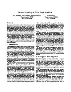
2.1. Programmable Logic Devices A programmable logic device is defined as a device with configurable logic and registers connected with programmable interconnections. Memory cells control and define the function of the logic and define how the various logic functions are interconnected. Though various types of devices use different architectures but all are based on this idea [Jacobson: 1999]. The most popular simple PLDs are Programmable Array Logic (PAL). The PAL are build of programmable AND gates, which are linked to a fixed OR gates (Fig. 2.2). This layout allows to implement logic functions of large number of variables represented as a sum of products. The size of device limits the number of terms which can be implemented in PAL device [Kania: 2004]. More advanced PALs are available with output logic macrocells (OLMCs). An alternative for PALs are Generic Array Logic (GAL) devices. This device has I3
I2
I1
OLMC O1 D
SET
CLR
Q
Q
Figure 2.2. The structure of a PAL device
the same logical properties as the PAL but they are made in different technology and they can be reprogrammed. Programmable Logic Arrays (PLAs) are very similar in comparison to PALs. They have also AND-OR structure but OR gates are also programmable (Tab. 2.1). Programmable Read-Only Memories (PROMs) can be also used for implementation of combinational circuits. There are fixed AND gates and programmable OR gates in this type of devices. The architecture of Complex Programmable Logic Devices (CPLDs) is based on PLD architecture [Skahill: 1996; Łuba et al.: 2003]. Simply it can by said that one CPLD is build from several PLDs. The main feature of CPLDs is existence of programmable interconnections (PIs) (Fig. 2.3). These connections combine logic blocks (LBs) and input/output -12-
2.2. Field Programmable Gate Arrays
Table 2.1. Classification of PLDs PROM
PLA
PAL
AND gates
fixed
programmable
programmable
OR gates
programmable
programmable
fixed
OLMCs
no
yes
yes
blocks (IOBs). Each logic block contains several macrocells and each macrocell is build LB
LB
IOB
LB
PI
LB
LB
IOB
LB
Figure 2.3. the structure of a CPLD
from a logic array and a programmable register [Altera: 2006; Xilinx: 2006b]. Typically logic arrays have a PAL based structure but there are also devices with a PLA structure of logic arrays [Xilinx: 2006a].
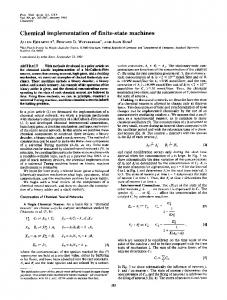
2.2. Field Programmable Gate Arrays FPGAs are built with matrix of small configurable logic blocks (CLBs), these blocks are connected by internal programmable interconnections and they are surrounded by programmable input/output blocks (IOBs) for communication with environment (Fig. 2.4) [Xilinx: 2004b; Altera: 2005a]. An FPGA contains from several to tens of thousands of CLBs. Each logic block is build of look-up tables (LUTs), flip-flops and some additional control logic (Fig. 2.5). There are two primary classes of FPGA architectures, coarse-grained and finegrained [Jacobson: 1999]. Fine-grained architectures consist of a large number of relatively simple logic blocks containing either a two-input LUT or a multiplexer and a flip-flop. The other architecture type is called coarse-grained. In these devices, there are fairly large CLBs, often containing two or more look-up tables and two or more flip-flops [Xilinx: 2002]. One
-13-
IOB
IOB
IOB
IOB
IOB
CLB
CLB
CLB
CLB
IOB
IOB
CLB
CLB
CLB
CLB
IOB
IOB
CLB
CLB
CLB
CLB
IOB
IOB
2.2. Field Programmable Gate Arrays
CLB
CLB
CLB
CLB
IOB
IOB
IOB
IOB
IOB
Figure 2.4. The structure of an FPGA COUT SET Y F[1:4] LUT
D
Carry & Control Logic
SET
CLR
Q
Q
X CIN CLK CLR
Figure 2.5. The structure of a CLB
LUT typically has 4 inputs and can implement any Boolean function of this number of variables. It works as 16×1 ROM. The new FPGAs have also embedded memory blocks [Bursky: 1999; Altera: 2007b]. These memories are from 512 b [Altera: 2007a] up to 36 Kb [Xilinx: 2007] (Tab. 2.2). The most popular size of memory block of cheaper FPGAs is 4 Kb [Xilinx: 2002; Altera: 2005b] and these blocks can be set to one of several modes of data width (Tab. 2.3). They can also work in one of modes, like single-port RAM, dual-port RAM or ROM. When embedded memory block works in ROM mode it is initiated with content during programming process of an FPGA device. In this mode, it can be used for implementation of combinational functions.
-14-
2.3. Designing with FPDs
Table 2.2. Size of memory blocks in FPGAs
Vendor
Xilinx
Altera
Size
Family
[bits]
Spartan
n/a
Spartan-II
4K
Spartan-3
18K
Virtex & Virtex-E
4K
Virtex-II & Virtex-II Pro
18K
Virtex-4
18K
Virtex-5
36K
Cyclone & Cyclone II
4K
Cyclone III
9K
Stratix & Stratix II
512 & 4K
Stratix III
640 & 9K
Table 2.3. Typical modes of embedded memory blocks
Mode
Number
Width
of words
of the word [bits]
4K×1
4096
1
2K×2
2048
2
1K×4
1024
4
512×8
512
8
256×16
256
16
2.3. Designing with FPDs The design process for FPDs is rather complicated. To simplify this process, there was created electronic design automation (EDA) software. This is special group of computeraided design (CAD) software that is dedicated to designing electronic systems ranging from printed boards to integrated circuits [Mc Cluskey: 1986]. These tools allow to create high level description of a behavior of a circuit and then automatically "fit" it into selected device. One of the most important steps, performed by these tools, is logic synthesis. -15-
2.3. Designing with FPDs
2.3.1. The design flow for FPDs The design flow for PLDs (Fig. 2.6) is different (and simpler) that the design flow for CPLDs and FGPAs. In this case, the behavior of a device is described in low-level PLD design
Description (ABEL. CUPL)
Compilation
JEDEC
Programming
Figure 2.6. The design flow for PLDs
languages like CUPL, ABEL or PALASM [Smith: 1997]. During compilation there is performed logic synthesis of design and Boolean equations in disjunction normal form describing behavior of device are obtained. These equations are minimized (and decomposed, if required [Devadas et al.: 1988; Kania: 2000]) also during compilation process. As a result the binary file (for example in JEDEC format) for programming the device is produced. CPLD and FPGA devices give much more possibilities than simple PLDs. It also makes that low-level languages are useless during design process for these devices. The most popular are hardware description languages (HDLs), like VHDL or Verilog, as design entry in a CPLD or FPGA design flow (Fig. 2.7) [Jenkins: 1994; Eles et al.: 1998]. HDLs allow to create a behavioral description of a digital system. It is very important that this description is device independent. The target device is chosen during a synthesis process. As a result
HDL Description
Synthesis
Netlist (EDIF, NGC)
Implementation
BitStream
Programming
Device Library
Figure 2.7. The design flow for FPGAs
of synthesis the netlist is obtained. This netlist consist description of design with use of blocks available in the target device. During this process functions describing behavior of a device can be decomposed in purpose of realization with available blocks [Devadas et al.: 1989; Rawski et al.: 2001]. This netlist is an input for an implementation process. During this process the design is mapped (in the CPLD flow this step is called "fit") into available -16-
2.3. Designing with FPDs
resources of a target device. Then the place & route step (only in the FPGA flow), which places and routes the design, is performed. As a result of implementation the programming file (bitstream) is generated. This file can be downloaded into a device.
2.3.2. Functional decomposition for FPDs The functional decomposition is an inseparable part of a synthesis process into FPDs. The architectural decomposition is made on higher level of designing process and after this process there is also required to preform the functional decomposition for obtained components. The goal of a decomposition depends on a type of a target device. Let analyze implementation of the function F F =
x1 x2 x3 x4 x5 x6 + x1 x2 x3 x4 x5 x6 + x1 x2 x3 x4 x5 x6 + x1 x2 x3 x4 x5 x6 + x1 x2 x3 x4 x5 x6 + x1 x2 x3 x4 x5 x6 + x1 x2 x3 x4 x5 x6 + x1 x2 x3 x4 x5 x6 + x1 x2 x3 x4 x5 x6 + x1 x2 x3 x4 x5 x6
on a PLD and an FPGA. This function depends on 6 variables and it has 10 terms. This function can not be minimized. Typical PLDs (PAL16H8, GAL16V8, GAL20V8) have 7 or 8 product terms per output. It means that the function F cannot be implemented on such device with use of 1 output. It leads to necessity of decomposition [Ciesielski & Yang: 1992; Łuba: 2001; Kania et al.: 2005a]. To implement the function F in device with 7 terms per output there have to be created the sub-function G G=
x1 x2 x3 x4 x5 x6 + x1 x2 x3 x4 x5 x6 + x1 x2 x3 x4 x5 x6 + x1 x2 x3 x4 x5 x6 + x1 x2 x3 x4 x5 x6 + x1 x2 x3 x4 x5 x6 + x1 x2 x3 x4 x5 x6
with 7 terms and then the function F can be written as function of the function G and the other 3 terms (Fig. 2.8) F = G + x1 x2 x3 x4 x5 x6 + x1 x2 x3 x4 x5 x6 + x1 x2 x3 x4 x5 x6 .
This is small example only for illustration of this problem. It is more discussed in literature by Prof. Dariusz Kania [2000] and it can also be extended into multi-output case [Kania et al.: 2005b]. The process of decomposition for CPLDs can be also improved by applying XOR gates [Kania & Grabiec: 2007] that are in new CPLD devices.
-17-
G
F
2.3. Designing with FPDs
x6 x5 x4 x3 x2 x1
Figure 2.8. The implementation of the function F on a PAL device
The bigger PLDs and CPLDs have more product terms per output (for example, GAL22V10 up to 16, Virtex XC9500 up to 90) but the problem of such decompositions appears also for functions with more terms that available terms per output. The most popular FPGAs have LUTs with 4 inputs. Such tables can implement any function up to 4 arguments. The example function F depends on 10 variables. It means that it also have to be decomposed [Łuba: 2001; Rawski et al.: 2006]. It this case it have to be decomposed into several sub-functions where each sub-function depends only on 4 variables or other sub-functions. In some FPGAs the 2-inputs multiplexers also can be used for implementation of logic functions and it leads to reduce a number of required LUTs. The example function F has to be implemented with 4 LUTs and 3 multiplexers on an FPGA device (Fig. 2.9). How it was shown the decomposition is very important during synthesis process, but the goal of decomposition depends on target architecture. It can be simply said that in case of PLDs and CPLDs the goal of decomposition is to extract sub-function with required number of terms and in case of FPGAs the goal of decomposition is to extract sub-function with
-18-
2.3. Designing with FPDs x1 F LUT1
x2 LUT2
x3 LUT3
G (LUT1) = x1 x 2 x 3 x 4 + x1 x 2 x 3 x 4 + x1 x 2 x 3 x 4
x4
LUT4
G (LUT 2) = x1 x 2 x 3 x 4 + x1 x 2 x 3 x 4 + x1 x 2 x 3 x 4 G (LUT 3) = x1 x 2 x 3 x 4 + x1 x 2 x 3 x 4
x5
G (LUT 4) = x1 x 2 x 3 x 4 + x1 x 2 x 3 x 4
x6
Figure 2.9. The implementation of the function F on a FPGA device
required numbers of arguments. Of course for implementation of system of functions there can be extracted common sub-function for several functions in order to diminish required hardware resources [Selvaraj et al.: 2006].
-19-
Chapter 3 Finite State Machines A finite state machine is a mathematical model of behavior composed of a finite set of input symbols, a finite set of states, a finite set of output symbols, transitions and actions [Baranov: 1994; Gajski: 1997; Łuba: 2001; Adamski & Barkalov: 2006]. This model can be represented as six tuple: S = hX, Y, A, a1 , δ, ωi,
(3.1)
where: X is a finite set of input symbols, X = {x1 , . . . , xL }; Y is a finite set of output symbols, Y = {y1 , . . . , yN }; A is a finite non empty set of states, A = {a1 , . . . , aM }; a1 is the initial state, a1 ∈ A; δ is a transition function, defined as a function of a state and input symbols: δ : A × X → A;
(3.2)
ω is an output function, in case of Moore model [Moore: 1956] defined as a function of a state: ω : A → Y,
(3.3)
and in case of Mealy model [Mealy: 1955] defined as a function of a state and input symbols: ω : A × X → Y.
(3.4)
The Mealy model can be treated as a general model of FSM and Moore model is its particular case. This is the main reason why this thesis refers to the Mealy model.
3.1. Methods of Specification of FSMs
3.1. Methods of Specification of FSMs The most popular graphical representation of FSMs are state diagrams [Gajski: 1997; Łuba: 2001; Adamski & Barkalov: 2006]. State diagram is a direct graph [De Micheli: 1994] where: • States are represented by a finite set of vertices, normally drown as a circle labeled inside with a state name; • Transitions are represented by direct edges, normally drown as an arrow from a current state to a next state, it is labeled with mapping of input symbols describing the logic condition of this transition; • Output symbols are represented by labels. For a Moore model this labels are assigned to states. For a Mealy model output symbols are represented by labels assigned to transitions, usually separated with a slash symbol "/" from input symbols; • The initial state typically is represented by an arrow pointing at it from nowhere [Hopcroft & Ullman: 1979]. The example of the Mealy FSM S1 and its state diagram is shown in the figure 3.1. There is already used structural alphabet. Others graphical representations of FSMs are graph-schemes of algorithms (GSA) [Baranov & Keevallik: 1980], algorithmic state machine (ASM) [Dagless: 1983a; Baranov: 1998a; Łuba: 2001] or flow-chart (FC) [Baranov: 1994; Barkalov & We¸grzyn: 2006]. All these four representations are very similar. In this work as graphical representation of algorithm a flowchart will be used. It consist of four types of vertices: • an initial vertex, • a finish vertex, • an operational node, • a conditional node. The states of Moore FSM are assigned to operational nodes and the states of Mealy FSM are placed on edges leaving an operational node. The flow-chart of the FSM S1 is shown in the figure 3.2. This type of representation is intuitive only for Moore FSMs and in case of Mealy FSMs it is more difficult for analysis than a state diagram. The GSA consist of these same types of nodes and the ASM has additionally the conditional output node and there is not initial and finish vertexes. The conditional output node defines Mealy type outputs -21-
3.1. Methods of Specification of FSMs
a)
b)
S1 = hX, Y, A, a1 , δ, ωi where
x1x2/y1
X = {x1 , x2 , x3 };
a1
Y = {y1 , y2 , y3 , y4 , y5 };
x1/y1y5
x1x2/y1y2
x2/y2
A = {a1 , a2 , a3 , a4 , a5 };
a5
δ(a1 , x1 , x2 ) = a2 , δ(a1 , x1 , x2 ) = a3 ,
x1x3/y3y4
δ(a1 , x2 ) = a3 , δ(a2 , x2 ) = a3 ,
x x /y y x1x3/y2y32 3 2 3
a4
δ(a3 , x2 , x3 ) = a4 ,
x2/y1y2 x2/y2
x3/-
x3/y3y4
δ(a2 , x2 ) = a4 , δ(a3 , x2 ) = a3 ,
a2
x2x3/y2 a3 x2/y2
δ(a3 , x2 , x3 ) = a5 , δ(a4 , x3 ) = a5 , δ(a4 , x3 ) = a3 , δ(a5 , x1 )=a1 , δ(a5 , x1 , x3 )=a5 , δ(a1 , x1 , x3 ) = a4 ; ω(a1 , x1 , x2 ) = y1 , ω(a1 , x1 , x2 ) = (y1 , y2 ), ω(a1 , x2 ) = y2 , ω(a2 , x2 ) = (y1 , y2 ), ω(a2 , x2 ) = y2 , ω(a3 , x2 ) = y2 , ω(a3 , x2 , x3 ) = y2 , ω(a3 , x2 , x3 ) = (y2 , y3 ), ω(a4 , x3 ) = (y3 , y4 ), ω(a5 , x1 ) = (y1 , y5 ), ω(a5 , x1 , x3 ) = (y3 , y4 ), ω(a1 , x1 , x3 ) = (y2 , y3 ). Figure 3.1. Mealy FSM S1 (a) and its state diagram (b) and Moore type outputs are assigned to operational nodes. The ASM diagram is like a state diagram but less formal. The other way to represent FSMs is use of tables. The most popular tables format is a state transition and output table. It can be presented as a classical two-dimensional table [Łuba: 2001; Adamski & Barkalov: 2006] or as a one-dimensional table. The onedimensional table looks like a truth table and typically it consists of four columns: • a current state, • a logic condition, • a next state, • outputs. It can be also extended by other columns that represent codes of states or excitation functions. Such table is also named as a direct structural table (DST) [Baranov: 1994; Barkalov & We¸grzyn: 2006]. The transition table for the FSM S1 is shown in the table 3.1. The biggest advantage of a table representation is that it can be easy represented by text formats. Such formats are very often used as an input description of FSMs by CAD tools for synthesis of -22-
3.1. Methods of Specification of FSMs
Start a1 1
1
0
x2
0
x1
y1
y1y2
y2
a2 a3 0
a4
1
x2
0
0
1
x2
1
x3
0
y2
x3
-
1
y3y4
y2y3
a5 0
x1
1 y1y5
0
x3
1 a1
y2y3
End
y3y4
Figure 3.2. The marked flow-chart Γ1 of the Mealy FSM S1
FSMs [Łuba et al.: 2003]. One of the most popular text format of a state transition and output table is the KISS2 format [Yang: 1991]. A file in this format consists of two parts: • a header, • a table. The header includes information about: .i - the number of inputs, .o - the number of outputs, -23-
3.1. Methods of Specification of FSMs
Table 3.1. The state transition and output table of the FSM S1 Current
Logic
Next
state
condition
state
x1 x2 x3 a1
a2 a3
a4 a5
Outputs y1 y2 y3 y4 y5
11−
a2
10000
01−
a3
11000
−0−
a4
01000
−1−
a3
11000
−0−
a4
01000
−1−
a3
01000
−00
a4
01000
−01
a5
01100
−−1
a5
00110
−−0
a3
00000
1−−
a1
10001
0−1
a5
00110
0−0
a4
01100
.p - the number of table lines - products, .s - the number of states, .r - the initial state (optional). The table describes the behavior (transitions) of a FSM. This table is a one-to-one equivalent to the one-dimensional state transition and output table. The table consist of four columns: • a logic condition, • a current state, • a next state, • output variables. The ’-’ sign in logic condition means that this input variable does not affect this transition. The ’0’ value means that negation of this variable should be placed in a logic condition and the ’1’ value that its affirmation should be placed in a logic condition. The KISS2 description of FSM S1 is shown in the figure 3.3. -24-
3.2. Realization of FSMs
.i 3 .o 5 .s 5 .p 13 .r a1 11- a1 01- a1 -0- a1 -1- a2 -0- a2 -1- a3 -00 a3 -01 a3 --1 a4 --0 a4 1-- a5 0-1 a5 0-0 a5
a2 a3 a4 a3 a4 a3 a4 a5 a5 a3 a1 a5 a4
10000 11000 01000 11000 01000 01000 01000 01100 00110 00000 10001 00110 01100
Figure 3.3. The KISS2 description of the FSM S1
3.2. Realization of FSMs Such defined a finite state machine (3.1) can be realized with use of programmable logic deices [Barkalov: 2002; Łuba et al.: 2003]. Synthesis process for PLDs consists of following steps [Barkalov: 2003; Łuba: 2005]: • an encoding of states, • a selection of flip-flop type, • a formation of the direct structural table, • a formation of the system of Boolean functions, • an implementation of the logic circuit of the FSM. The encoding of states (state assignment) is one of most important steps of synthesis process [Lee & Hwang: 1993; Kubátová: 2005; Borowik: 2005]. There is required to use R bits to encode states am ∈ A = {a1 , . . . , aM }, where dlog2 M e 6 R 6 M.
(3.5)
The value of R depends on the method of encoding and for binary, Gray or Johnson encoding (called minimum-length or compact methods) R = dlog2 M e,
-25-
(3.6)
3.2. Realization of FSMs
but for one-hot encoding there is required to use maximal number of bits and R = M.
(3.7)
There are also others methods, like two-hot, where the number of required bits is between dlog2 M e and M . The selection of one method depends on target architecture and system requirements. Typically, in case of FPGAs, one-hot methods gives the highest frequency of device but also required the most number of logic elements [Kubátová: 2005]. The alternative to save logic elements are minimum-length methods. The selection of flip-flop type very often depends on target architecture. The most popular, embedded in PLD, CPLD or FPGA devices, are D type flip-flops [Jenkins: 1994]. In case of other target architecture selection of JK or T type flip-flops, or a mix of flip-flops can reduce number of required logic elements for implementation of a combinational part of a FSM [Ahmad et al.: 2000]. The formation (construction) of the direct structural table is base for formation of a system of microoperations (µOs): Y = Y (X, Q),
(3.8)
that is based on interpretation of definition of the Mealy type outputs function (3.4) and a system of excitation functions: Φ = Φ(X, Q),
(3.9)
that is interpretation of definition of the state transition function (3.2) [Barkalov: 1994b]. These systems are implemented by the circuit P (Fig. 3.4) of the single-level circuit of a Mealy FSM (called P Mealy FSM) [Barkalov: 1994a]. Y
X
P Φ
RG
Q
Figure 3.4. The structural diagram of P Mealy FSM
The direct structural table of a Mealy FSM has following columns [Baranov: 1994]: am is current state of a FSM, am ∈ A where A = {a1 , . . . , aM } is the set of states; K(am ) is a binary code of the state am , the code is represented by variables Qr ∈ Q = {Q1 , . . . , QR }; -26-
3.2. Realization of FSMs as is a state of the transition, as ∈ A; K(as ) is a binary code of the state as ; Xh is a logic condition, it causes the transition from the state am to the state as (ham , as i) and it is equal to the conjunction of affirmation or negation of some elements of the set X = {x1 , . . . , xL }; Yh is a microinstruction (µI) formed during the transition ham , as i, Yh ⊆ Y where Y = {y1 , . . . , yN } is the set of microoperations; Φh is a subset of the set of excitation functions Φ that are equal to 1 to switch the memory of a FSM from K(am ) to K(as ), Φ = {D1 , . . . , DR } in case of D type flip-flops; h is a number of the transition, h = 1, . . . , H. Each row of a direct structural table represents one transition. The formation (construction) of the system of Boolean functions is base for obtaining systems (3.8) and (3.9). From each line of a DST can be formed term Fh = Ahm ∧ Xh ,
(3.10)
where Ahm is a conjunction of internal variables Qr ∈ Q corresponding to the code K(am ) of the state am ∈ A from the h-th line of the DST Ahm
=
R ^
Qlrmr ,
(3.11)
r=1
where lmr ∈ {0, 1} is a value of the r-th bit of the code K(am ):Q0r = Qr and Q1r = Qr . Now, systems (3.8) and (3.9) are defined as: yn =
H � _
� Cnh ∧ Fh ,
(3.12)
h=1
Dr =
H � _
� Crh ∧ Fh ,
(3.13)
h=1
where n = 1, . . . , N , r = 1, . . . , R; Cnh (Crh ) is a Boolean variable equal to 1 iff the hth line of a DST contains the function yn (Dr ) in the column Yh (Φh ) [Barkalov & Palagin: 1997]. These systems are represented in a disjunctive normal form (DNF). This is the most common form of representation of Boolean equations for direct implementation in PLD devices but sometimes, for different technologies, they have to be transformed into other form. -27-
3.2. Realization of FSMs
For example, for implementation with NAND gates, De-Morgan laws have to be applied to transform systems (3.12) and (3.13) [Sasao: 1999]. These equations can be also minimized before implementation [Zieli´nski: 2003]. Very often minimization with include of don’t care values gives better results. This type of minimization can be performed with use of Karnaugh maps. The implementation of the logic circuit of the FSM. The combinational circuit P, represented by systems (3.12) and (3.13), implements p-functions of a FSM and the number of such functions is: nP (P) = R + N.
(3.14)
It is implemented using combinational logic of a FPD device. The register RG is implemented with use of R flip-flops of a FPD device (typically D-type). The method of implementation depends on a type of a FPD device [Solovjev: 2001a]. For FPGA devices, the combinational circuit P is implemented with use of LUTs and the register RG is implemented with use of flip-flops of logic blocks. Because typical LUT has only 4 inputs very often Boolean functions have to be decomposed [Łuba et al.: 2002] because typically they have more than 4 arguments. The direct structural table for the FSM S1 with binary encoding of states and with D-type flip-flops is presented in the table 3.2. There can be obtained Boolean equations of systems (3.12) and (3.13) based on this table, for example1 : y1 = Q1 Q2 Q3 x1 x2 + Q1 Q2 Q3 x1 x2 + Q1 Q2 Q3 x2 + Q1 Q2 Q3 x1 , D1 = Q1 Q2 Q3 x2 x3 + Q1 Q2 Q3 x3 + Q1 Q2 Q3 x1 x3 . Of course these equations can be written in minimized form: y1 = Q1 Q2 x2 + Q1 Q2 Q3 x1 , D1 = Q1 Q2 Q3 x2 x3 + Q1 Q2 x3 + Q1 Q2 Q3 x1 x3 . How it can be saw, the number of terms is smaller after minimization and it is important in case of implementation with PLDs, but the number of variables is the same before and after minimization and in case of implementation with FPGAs this minimization do not give any benefits. 1
There is used mathematical notation ("∧" - logical and, "∨" - logical or) in definitions but in regular
equations there is used engineering notation (""(no symbol) - logic and, "+" - logical or) to make them more readable.
-28-
3.3. Decomposition of Circuit of FSM
Table 3.2. The DST of the Mealy FSM S1 am
K(am )
as
K(as )
Xh
Yh
Φh
h
a1
000
a2
001
x1 x2
y1
D3
1
a3
010
x1 x2
y1 y2
D2
2
a4
011
x2
y2
D2 D3
3
a3
010
x2
y1 y2
D2
4
a4
011
x2
y2
D2 D3
5
a3
010
x2
y2
D2
6
a4
011
x2 x3
y2
D2 D3
7
a5
100
x2 x3
y2 y3
D1
8
a5
100
x3
y3 y4
D1
9
a3
010
x3
−
D2
10
a1
000
x1
y1 y5
−
11
a5
100
x1 x3
y3 y4
D1
12
a4
011
x1 x3
y2 y3
D2 D3
13
a2 a3
a4 a5
001
010
011
100
3.3. Decomposition of Circuit of FSM The most important problem of implementation into FPGAs of sing-level P Mealy FSM is that there have to be implemented large number (up to 200) of Boolean functions dependable on large number (up to 100) of arguments [Baranov: 1994]. If the number of arguments of a Boolean function exceeds a number of LUT inputs there is required to apply functional decomposition of this function [Łuba et al.: 2003] but this process does not reduce the total number of Boolean functions. There are also methods of synthesis combinational part of a FSM as ROM [Łuba et al.: 2003]. To diminish the numer of Boolean functions there can be applied architectural decomposition of a structure of a logic circuit implementing a FSM [Adamski & Barkalov: 2006]. This manipulation leads to multi-level circuit of a Mealy FSM and the combinational part implements less Boolean functions that equivalent single-level circuit.
3.3.1. Functional Decomposition for FPGAs Curtis’ theorem [1962]: a function f (x0 , x1 , . . . , xn−1 ) is decomposable under the bound set B = {x0 , . . . , xi−1 } and the free set A = {xi , . . . , xn−1 }, 0 < i < n − 1, A ∩ B = ∅,
-29-
3.3. Decomposition of Circuit of FSM the f can be represented as the composite function h(g1 (B), . . . , gj (B), A), 0 < j < i − 1: f (x0 , x1 , . . . , xn−1 ) = h(g1 (B), . . . , gj (B), A).
(3.15)
The scheme of this decomposition is shown in the figure 3.5. B
A
x0
xi
xi-1
xn-1
G g1
gj
H f
Figure 3.5. The scheme of the Curtis’ functional decomposition
The decomposition can be also performed for case where A∩B 6= ∅ [Łuba: 2001]. In this case the bound set B = {x0 , . . . , xi−1 } and the free set A = {xi−l , . . . , xn−1 }, 0 < i < n−1, 1 < l < i − 1, A ∩ B = {xi−l , . . . , xi−1 }. The scheme of this case is shown in the figure 3.6.
B x0
xi-l
A xn-1
xi-1
G g1
gj
H f
Figure 3.6. The scheme of the general functional decomposition
This theorem can be extended for a set of Boolean functions [Łuba et al.: 2003]: F (A, B) = H(G1 (B), . . . , Gj (B), A). -30-
(3.16)
3.3. Decomposition of Circuit of FSM
There are many analytical methods of a functional decomposition [Scholl: 2001; Łuba et al.: 2002]. The binary decision diagrams (BDDs) can be also applied for improvement of a functional decomposition [Opara & Kania: 2007]. Most popular computer systems for functional decomposition are SIS (Sequential Interactive System) from Berkeley [Sentovich et al.: 1992] and DEMAIN from Warsaw University of Technology [Nowicka: 1999]. The SIS system is multitasking system and it transforms a logical description into a multilevel gates array [Sentovich et al.: 1992]. The minimization of Boolean functions is based on ESPRESSO system [Brayton et al.: 1984]. There is also proceeded a classical algorithm of a functional decomposition and it allows decomposition of single Boolean function. The DEMAIN system decomposes Boolean functions base on original algorithm [Nowicka: 1999] combining serial and parallel decomposition. There also algorithms of special encoding for parallel decomposition [Borowik: 2005]. The separate algorithms are designed for a decomposition of functions dependable on large number of arguments [Rawski et al.: 2006]. Also decomposition of Boolean functions of a FSM can be applied on symbolic level [Rawski et al.: 2005b; Szotkowski & Rawski: 2007]. All these manipulations can reduce a number of required LUTs [Rawski et al.: 2005] for implementation of a FSM but these algorithms do not affect the total number of functions realized by a combinational part of a FSM.
3.3.2. Realization of FSMs with ROM Memories The new FPGA devices are embedded with memory blocks (Chap. 2.2). It gives opportunity to come back to old methods of designing of a combinational circuit as ROM [Dagless: 1983b] and implement a combinational part of a FSM in memory blocks (Fig. 3.7 a) operating in ROM mode [Łach et al.: 2003]. But, typically, this required a lot of memory resources and many words are not used because truth tables describing such circuits are not strongly specified. To reduce memory size the address converter (AC) (Fig. 3.7 b) can be applied [Łach et al.: 2003; Senhadji-Navarro et al.: 2004] and it can be implemented with LUTs because it is described by a set of Boolean functions. It leads to the structure similar to the microprogram control unit (MCU) [Barkalov & Palagin: 1997; Barkalov & Titarenko: 2007a,b]. This process of synthesis can be improved also by applying functional decomposition [Rawski et al.: 2005a] or by partitioning a memory into several blocks [Borowik: 2004, 2007]. The disadvantage of this method of designing is that there is not optimal, very big, memory on the beginning and results of reduction are not predictable. The alternative solution for this realization is architectural decomposition [Solovjev: 2001b; Adamski &
-31-
3.3. Decomposition of Circuit of FSM X
AC X 1 and k = 1 for i = 1, l = k + ni − 1. i0 =1
The formation of the transformed direct structural table is similar to the previous synthesis method with the maximal encoding of microinstructions. The only difference is a rule of putting variable in the column Zh . This column consist variables zn ∈ Z, n = 1, . . . , N1 , that are equal to 1 in codes K(yn ), n = 1, . . . , N , of microoperations yn belonging to the microinstruction Yt from the h-th line of the original DST. The step of the formation of the system of Boolean functions is exactly the same as for the previous synthesis method with maximal encoding of microinstructions.
-36-
3.3. Decomposition of Circuit of FSM
The formation of the decoder tables. This step forms the tables that describe behavior of the circuit D (3.18). Because this circuit is build from a set of I decoders there is required to create I tables, one for each decoder Di . Such table has three columns: K(yn ) is a binary code of the microoperation yn ; Y i is a binary representation of the i-th class of compatible microoperations for the code K(yn ); h is a number of the line, h = 1, . . . , (|Y i | + 1). The implementation of the logic circuit of the FSM. The implementation of circuits P and RG is exactly the same as for the previous synthesis method with the maximal encoding of microinstructions. Of course the number of realized p-functions by the circuit P can be different because of different value of parameter N1 (3.23) and it is equal to: nP (PD) = R + N1 .
(3.25)
Decoders Di can be implemented using embedded memory blocks or with LUTs. There can be obtained the partition ΠY = {Y 1 , Y 2 }, Y 1 = {y1 , y3 }, Y 2 = {y2 , y4 , y5 } for the FSM S1 . In this case N1 = 4 and microoperations can be encoded like this: K(y1 ) = 01, K(y3 ) = 10, K(y2 ) = 01, K(y4 ) = 10, K(y5 ) = 11. The code 00 is reserved for situation when no microoperation is executed from particular class. The transformed direct structural table for the FSM S1 is presented in the table 3.5. Base on this table there can be obtained Boolean equations of systems (3.12) and (3.20), for example: z1 = Q1 Q2 Q3 x1 x2 + Q1 Q2 Q3 x1 x2 + Q1 Q2 Q3 x2 + Q1 Q2 Q3 x1 . In case of such encoding nP (PD) = 7. The table of the decoder D (joined tables of decoders D1 and D2 ) for the FSM S1 is shown in the table 3.6. The disadvantage of this method is also relatively large number of Boolean functions implemented by the combinational circuit P. Implementation of the decoder D is also not effective. If it is implemented with use of memory blocks it required I such blocks and if it is implemented with LUTs very often the total number of required LUTs for implementation of circuits P and D is bigger than a number of LUTs required for implementation of the same algorithm with use of the single-level structure P. It makes that this method is used even rearer in an FPGA synthesis process and the improvements of this method gives also benefits only for PLDs [Barkalov & Bukowiec: 2005a].
-37-
3.3. Decomposition of Circuit of FSM
Table 3.5. The transformed DST of the PD Mealy FSM S1 am
K(am )
as
K(as )
Xh
Zh
Φh
h
a1
000
a2
001
x1 x2
z1
D3
1
a3
010
x1 x2
z1 z3
D2
2
a4
011
x2
z3
D2 D3
3
a3
010
x2
z1 z3
D2
4
a4
011
x2
z3
D2 D3
5
a3
010
x2
z3
D2
6
a4
011
x2 x3
z3
D2 D3
7
a5
100
x2 x3
z3 z2
D1
8
a5
100
x3
z2 z4
D1
9
a3
010
x3
−
D2
10
a1
000
x1
z1 z3 z4
−
11
a5
100
x1 x3
z2 z4
D1
12
a4
011
x1 x3
z3 z2
D2 D3
13
a2 a3
a4 a5
001
010
011
100
Table 3.6. Decoders table of the PD Mealy FSM S1 Y1
K(yn ) z1 z2
y1
y3
00
0
0
01
0
10
1
h
Y2
K(yn )
h
z3 z4
y2
y4
y5
1
00
0
0
0
1
1
2
01
0
1
0
2
0
3
10
1
0
0
3
11
0
0
1
4
Both presented methods are effective for PLDs but they do not give benefits in an FPGA synthesis process. The reason is that they still have large number of Boolean functions and usage of embedded memory blocks of FPGA devices is not effective. But it shows that application of architectural decomposition could be also considered as a good trend in an FPGA synthesis process. Of course there are required modifications of these methods for purpose of further reduction of number of Boolean functions and more effective usage of FPGA memory blocks. Such modifications are proposed in next chapter. It should be mentioned here that functional and architectural decompositions have differ-38-
3.3. Decomposition of Circuit of FSM
ent nature. How it was described above, the functional decomposition operates on Boolean functions obtained during the synthesis process and it is preformed in its final phase. The architectural decomposition operates on a system level and it is applied during the synthesis process. It means that these both decomposition methods should not be treated as competitive ones and what more they can be applied together in the synthesis process.
-39-
Chapter 4 Multi-Level Structures of Mealy FSMs Previously presented methods can be adopted into an FPGA technology. It required application of special methods of encoding [Barkalov et al.: 2005; Bukowiec & Barkalov: 2007] and modification of a logic circuit structure and sometimes also transformation of a control algorithm [Bukowiec: 2006b; Bukowiec & Barkalov: 2006]. Proposed methods base on a multiple encoding [Bukowiec: 2005a] of some parameters of a state machine. The structure of logic circuits depends which parameter is multiple encoded and which parameter is used as a partial code. A multiple encoding can be applied for some parameters of a state machine, like microinstructions or internal states [Bukowiec: 2004a]. The set of these parameters is partitioned into several subsets. Then parameters are encoded separately in each subset. The same codes are used for different subsets. The partition into subsets is made base on other parameter, like a current state or a currently executed microinstruction. The logic circuit of such designed state machine required special structure and type of blocks and their connections and it depends on which parameter is multiple encoded and which parameter is used as a partitioning set. Generally, such circuit is realized in a double-level structure with a combinational circuit on a first level and a decoder on a second level.
4.1. Multiple Encoding of Microinstructions The first of proposed methods applies multiple encoding for a set of microinstructions and it is a further modification of the method with a maximal encoding of microinstructions [Bukowiec: 2004a]. Let partition a set of all microinstructions Υ = {Y1 , . . . , YT } into subsets based on a current state am . It leads to existence of M subsets Υ(am ) ⊆ Υ and a microinstruction Yt ∈ Υ(am ) iff it is executed during any transition from the state am . Let Tm = |Υ(am )|
(4.1)
4.1. Multiple Encoding of Microinstructions
and T0 = max(T1 , . . . , TM ).
(4.2)
Let encode each microinstruction Yt ∈ Υ(am ) by a binary code Km (Yt ) with N2 = dlog2 T0 e
(4.3)
bits. Because Υ(am ) ⊆ Υ (T0 6 T ) then N2 6 N1 . But for typical control algorithm Υ(am ) ⊂ Υ and T0 < T and in this case also N2 < N1 and this condition have to be satisfied for benefits from application of this method [Barkalov & Bukowiec: 2004b]. Let use variables ψn ∈ Ψ = {ψ1 , . . . , ψN2 } for representation of codes Km (Yt ). In this case the code of a microinstruction K(Yt ) is represented by concatenation of the multiple code of the microinstruction Km (Yt ) and the code of the current state K(am ): K(Yt ) = Km (Yt ) ∗ K(am ).
(4.4)
A digital circuit of a FSM with such encoding can be implemented as a double-level structure PY0 (Fig. 4.1). This structure permits to decrease the number of outputs of the circuit P in comparison with the structure PY. Here the circuit P implements the system (3.9) and the Ψ
X
P
Y Φ
Y
RG
Q
Figure 4.1. The structural diagram of PY0 Mealy FSMs
system Ψ = Ψ(X, Q).
(4.5)
nP (PY0 ) = R + N2
(4.6)
It has to implement
p-functions. The circuit Y implements a decoding system Y = Y (Ψ, Q),
(4.7)
where the variables from the set Ψ are used to detect a adequate microinstruction for current state that is identified be variables from the set Q. -41-
4.1. Multiple Encoding of Microinstructions
The entering point for architectural decomposition is a formatted DST and it consists from following steps: • a multiple encoding of microinstructions, • a formation of the transformed direct structural table, • a formation of the system of Boolean functions, • a formation of the decoder table, • an implementation of the logic circuit of the FSM. The multiple encoding of microinstructions is based on binary encoding of microinstructions Yt in each subset Υ(am ). It means that if one microinstruction Yt belongs to several subsets Υ(am ) it also receives several codes Km (Yt ). The formation of the transformed direct structural table is base for formation of systems (3.9) and (4.5). It is created from the original DST by replacing the column Yh by the column Ψh . The column Ψh contains variables ψn ∈ Ψ, n = 1, . . . , N2 , that are equal to 1 in the code Km (Yt ) of the microinstruction Yt from the h-th line of the original DST. The formation of the system of Boolean functions is base for obtaining systems (3.9) and (4.5). The system (3.9) is defined as (3.13), exactly the same as for P or PY Mealy FSMs. Based on the similar way system (4.5) is defined as: � H � _ ψn = Cnh ∧ Fh ,
(4.8)
h=1
where n = 1, . . . , N2 ; Cnh is a Boolean variable equal to 1 iff the h-th line of the transformed DST contains the function ψn in the column Ψh . The formation of the decoder table. This step forms the table that describes behavior of the circuit Y (4.7). This table has four columns: K(am ) is a binary code of the current state am ; Km (Yt ) is a binary code of the microinstruction Yt from the subset Υ(am ); y1 , . . . , yN is a binary representation of the microinstruction Yt , yn = 1 iff yn ∈ Yt and yn = 0 iff yn 6∈ Yt , n = 1, . . . , N ; t0 is a number of the line, t0 = 1, . . . ,
M X
Tm .
m=1
The implementation of the logic circuit of the FSM. The combinational circuit P, represented by systems (3.12) and (4.8) is implemented by LUTs, and the register RG is implemented by D flip-flops. The decoder Y is implemented using an embedded memory block -42-
4.1. Multiple Encoding of Microinstructions with 2(R+N2 ) words of N bits and the content of the memory is described by the decoder table where the concatenation of a binary code of a current state and a binary code of a microinstruction (4.4) is an address and the binary representation of a microinstruction is a value of word. There can be assigned any (don’t care) values for addresses omitted in decoder tables because such concatenations of both codes are never used. It should be mentioned here that memory blocks in popular FPGAs are synchronous ones [Altera: 2007a; Xilinx: 2002] and it means that they additionally work also as an output register but such registers are needed in each digital system with Mealy’s outputs to stabilize its operation [Barkalov: 2003; Jantsch: 2003]. There is T = 7 differen microinstructions in the FSM S1 and they can be partitioned into M = 5 subsets: Υ(a1 ) = {Y1 , Y2 , Y3 }, Υ(a2 ) = {Y2 , Y3 }, Υ(a3 ) = {Y3 , Y4 }, Υ(a4 ) = {Y5 , Y6 } and Υ(a5 ) = {Y4 , Y5 , Y7 }. In this case N2 = 2 and microinstructions can be encoded like this: K1 (Y1 ) = 00, K1 (Y2 ) = 01, K1 (Y3 ) = 10, K2 (Y2 ) = 00, K2 (Y3 ) = 01, . . . , K5 (Y5 ) = 01, K5 (Y7 ) = 10. The transformed direct structural table for the FSM S1 is presented in the table 4.1. Base on this table there can be obtained Boolean equations of Table 4.1. The transformed DST of the PY0 Mealy FSM S1 am
K(am )
as
K(as )
Xh
Ψh
Φh
h
a1
000
a2
001
x1 x2
−
D3
1
a3
010
x1 x2
ψ2
D2
2
a4
011
x2
ψ1
D2 D3
3
a3
010
x2
−
D2
4
a4
011
x2
ψ2
D2 D3
5
a3
010
x2
−
D2
6
a4
011
x2 x3
−
D2 D3
7
a5
100
x2 x3
ψ2
D1
8
a5
100
x3
−
D1
9
a3
010
x3
ψ2
D2
10
a1
000
x1
ψ1
−
11
a5
100
x1 x3
ψ2
D1
12
a4
011
x1 x3
−
D2 D3
13
a2 a3
a4 a5
001
010
011
100
systems (3.12) and (4.8), for example: ψ1 = Q1 Q2 Q3 x2 + Q1 Q2 Q3 x1 . -43-
4.2. Multiple Encoding of Internal States
The table of the decoder Y for the FSM S1 is shown in the table 4.2. Because this table can Table 4.2. The decoder table of the PY0 Mealy FSM S1 K(am )
Km (Yt )
Q1 Q2 Q3
ψ1 ψ2
y1
y2
y3
y4
y5
000
00
1
0
0
0
0
1
01
1
1
0
0
0
2
10
0
1
0
0
0
3
00
1
1
0
0
0
4
01
0
1
0
0
0
5
00
0
1
0
0
0
6
01
0
1
1
0
0
7
00
0
0
1
1
0
8
01
0
0
0
0
0
9
00
0
1
1
0
0
10
01
0
0
1
1
0
11
10
1
0
0
0
1
12
001
010
011
100
Yt
t0
be directly implemented as a memory block there is no need to form Boolean equations for the system (4.7). There are nP (PY0 ) = 5 Boolean functions implemented by the combinational circuit P of PY0 Mealy FSM where, for comparison, there are nP (P) = 8 or nP (PY) = 6 such functions, respectively, in P or PY Mealy FSMs. It is shown that even for such small example the number of Boolean functions can be decreased in comparison with well known structures and methods of synthesis. The gain is bigger for state machines that execute more microinstructions [Barkalov & Bukowiec: 2005b] and it is scrupulously discussed in chapter 5.
4.2. Multiple Encoding of Internal States The synthesis method with multiple encoding of internal states [Bukowiec: 2004a; Barkalov & Bukowiec: 2004c, 2007] is similar to the previous one but in this case the set of internal states is partitioned into several subsets. Additionally, current states [Bukowiec: 2005a] or microinstructions [Barkalov & Bukowiec: 2004a] can be treated as a partitioning set. -44-
4.2. Multiple Encoding of Internal States
4.2.1. Multiple Encoding of Internal States with Current States as a Partitioning Set Let partition the set of internal states as ∈ A = {a1 , . . . , am } into subsets based on a current state am ∈ A. It leads to existence of M subsets A(am ) ⊆ A and a internal state as ∈ A(am ) iff it is the state of transition from the state am . Let A Mm = |A(am )|
(4.9)
and A M0A = max(M1A , . . . , MM ).
(4.10)
Let encode each internal state as ∈ A(am ) by a binary code Km (as ) with R1 = dlog2 M0A e
(4.11)
bits. In a theoretical case A(am ) ⊆ A (M0A 6 M ) ⇒ R1 6 R. But in a typical state machine A(am ) ⊂ A and M0A < M and of course R1 < R and this condition have to be satisfied for benefits from application of this method. Let use variables τr ∈ T = {τ1 , . . . , τR1 } for representation of Km (as ) codes. In this case the code of internal state K(as ) is represented by concatenation of the multiple code of the internal state Km (as ) and the code of the current state K(am ): K(as ) = Km (as ) ∗ K(am ).
(4.12)
A digital circuit of a FSM with such encoding can be implemented as the single-level structure PA (Fig. 4.2 a). There can be also applied the maximal encoding of microinstructions and in this case the double-level structure PAY (Fig. 4.2 b) is received during synthesis process. Theses structures permit to decrease the number of outputs of the circuit P in comparison with, respectively, P and PY structures [Bukowiec & Barkalov: 2007]. Here the circuit P
Y Y
X
X
P
P Τ
a)
Z
CC
Φ
Q
Τ
RG b)
CC
Φ
RG
Q
Figure 4.2. The structural diagram of PA (a) and PAY (b) Mealy FSMs
-45-
Y
4.2. Multiple Encoding of Internal States
implements the system (3.8) – the structure PA or (3.17) – the structure PAY and the system T = T(X, Q),
(4.13)
nP (PA) = R1 + N.
(4.14)
nP (PAY) = R1 + N1 .
(4.15)
and it implements, respectively,
or
p-functions. The optional circuit Y implements a decoding of microinstructions system (3.18). There is additional circuit CC that decode internal states and generate a excitation function system: Φ = Φ(T, Q),
(4.16)
where the variables from the set T are used to detect a next state for current state that is identified be variables from the set Q. The starting point for architectural decomposition is the formatted DST and it consist from following steps: • an encoding of microinstructions (only for the structure PAY), • a multiple encoding of internal stares, • a formation of the transformed direct structural table, • a formation of the system of Boolean functions, • a formation of the microoperation decoder table (only for the structure PAY), • a formation of the internal state code converter table, • a implementation of the logic circuit of the FSM. The encoding of microinstructions. This step is exactly the same as for the structure PY and it is described in the chapter 3.3.3.1. The multiple encoding of internal states is based on assigning a binary code Km (as ) to internal states as in each subset A(am ). The formation of the transformed direct structural table is base for formation of systems (3.8) or (3.17) and (4.13). It is created from the original DST by replacing the column Yh by the column Zh (only for the structure PAY) and columns K(as ) and Φh with columns Km (as ) and Th . The column Km (as ) contains the multiple code of the internal state. The column Th contains variables τr ∈ T, r = 1, . . . , R1 , that are equal to 1 in the code Km (as ) from the same line of the DST. -46-
4.2. Multiple Encoding of Internal States
The formation of the system of Boolean functions is base for obtaining systems (3.8) or (3.17) and (4.13). Systems (3.8) and (3.18) are defined as, respectively, (3.12) and (3.20), exactly the same as for P and PY Mealy FSMs. Based on the similar way system (4.13) is defined as: τr =
H � _
� Crh ∧ Fh ,
(4.17)
h=1
where r = 1, . . . , Rr ; Crh is a Boolean variable equal to 1 iff the h-th line of the transformed DST contains the function τr in the column Th . The formation of the microoperation decoder table. This step is exactly the same as for the structure PY and it is described in the chapter 3.3.3.1. The formation of the internal state code converter table. This step forms the table that describe behavior of the circuit CC (the system 4.16). This table has four columns: K(am ) is a binary code of the current state am ; Km (as ) is a binary code of the internal state as from the subset A(am ); D1 , . . . , DR is a binary representation of excitation functions that switches the memory of the FSM from K(am ) to K(as ), in case of D type flip-flops Dr = Q∗r , r = 1, . . . , R; m0 is a number of the line, m0 = 1, . . . ,
M X
A Mm .
m=1
The implementation of the logic circuit of the FSM. The combinational circuit P is implemented by LUTs. The decoder Y is implemented using an embedded memory block as for the structure PY. The internal state converter CC is also implemented into an embedded memory block with 2(R+R1 ) words of R bits and the content of the memory is described by the internal state code converter table where the concatenation of the binary code of the current state and the binary code of the internal state (4.12) is an address and the binary representation of excitation functions is a value of the word. There can be assigned any (don’t care) values for addresses omitted in the table because such concatenations of both codes are never used. Because memory blocks in popular FPGAs are synchronous ones [Altera: 2007a; Xilinx: 2002] there is no need to implement the register RG because the circuit CC also fulfills this function. In this case value of the word is representing the code of the next state and because Dr = Q∗r there is no need to modification of internal state code converter table. By application of this encoding all internal states of the FSM S1 can be partitioned into M = 5 subsets: A(a1 ) = {a2 , a3 , a4 }, A(a2 ) = {a3 , a4 }, A(a3 ) = {a3 , a4 , a5 }, A(a4 ) = -47-
4.2. Multiple Encoding of Internal States {a3 , a5 } and A(a5 ) = {a1 , a4 , a5 }. In this case M1A = 3, M2A = 2, M3A = 3, M4A = 2 and M5A = 3 ⇒ M0A = 3 ⇒ R1 = 2 and internal states can be encoded this way: K1 (a2 ) = 00, K1 (a3 ) = 01, K1 (a4 ) = 10, K2 (a3 ) = 00, K2 (a4 ) = 01, . . . , K5 (a4 ) = 01, K5 (a5 ) = 10. The transformed direct structural table for the FSM S1 is presented in the table 4.3. Base on this table there can be obtained Boolean equations of systems (3.12) and (4.17), for Table 4.3. The transformed DST of the PA Mealy FSM S1 am
K(am )
as
Km (as )
Xh
Yh
Th
h
a1
000
a2
00
x1 x2
y1
−
1
a3
01
x1 x2
y1 y2
τ2
2
a4
10
x2
y2
τ1
3
a3
00
x2
y1 y2
−
4
a4
01
x2
y2
τ2
5
a3
00
x2
y2
−
6
a4
01
x2 x3
y2
τ2
7
a5
10
x2 x3
y2 y3
τ3
8
a5
00
x3
y3 y4
−
9
a3
01
x3
−
τ2
10
a1
00
x1
y1 y5
−
11
a5
10
x1 x3
y3 y4
τ1
12
a4
01
x1 x3
y2 y3
τ2
13
a2 a3
a4 a5
001
010
011
100
example: τ1 = Q1 Q2 Q3 x2 + Q1 Q2 Q3 x1 x3 . The table of the decoder CC for the FSM S1 is shown in the table 4.4. Because this table can be directly implemented as a memory block there is no need to form Boolean equations for the system (4.16). Additionally there can be applied the maximal encoding of microinstructions and it leads to realization of FSM in the structure PAY. There are nP (PA) = 7 for the structure PA or nP (PAY) = 5 for the structure PAY Boolean functions implemented by the combinational circuit P where, for comparison, there are nP (P) = 8 or nP (PY) = 6 such functions in well known methods of synthesis. The gain is bigger for state machines with large number of states and small number of different states of transitions from one state and it is scrupulously discussed in next chapters.
-48-
4.2. Multiple Encoding of Internal States
Table 4.4. The internal state code converter table of the PA Mealy FSM S1 K(am )
Km (as )
Q1 Q2 Q3
τ1 τ2
000
001
010
011
100
D1
D2
D3
m0
00
0
0
1
1
01
0
1
0
2
10
0
1
1
3
00
0
1
0
4
01
0
1
1
5
00
0
1
0
6
01
0
1
1
7
10
1
0
0
8
00
0
1
0
9
01
1
0
0
10
00
0
0
0
11
01
0
1
1
12
10
1
0
0
13
4.2.2. Multiple Encoding of Internal States with Microinstructions as a Partitioning Set In this approach, let partition the set of internal states as ∈ A = {a1 , . . . , am } into subsets based on currently executed microinstruction Yt ⊆ Y . It means that there is also required application of the maximal encoding of microinstructions because a usage of microinstructions codes only makes sense – all microoperations create too long vector. It leads to existence of T subsets A(Yt ) ⊆ A and the internal state as ∈ A(Yt ) iff it is the state of transition when the microinstruction Yt is executed. Let MtY = |A(Yt )|
(4.18)
M0Y = max(M1Y , . . . , MTY ).
(4.19)
and
Let encode each internal state as ∈ A(Yt ) by a binary code Kt (as ) with R2 = dlog2 M0Y e -49-
(4.20)
4.2. Multiple Encoding of Internal States bits. In theory A(Yt ) ⊆ A and (M0Y 6 M ) ⇒ R2 6 R, but for implementation of typical algorithms A(Yt ) ⊂ A and M0Y < M and it leads to R1 < R and this condition have to be satisfied for benefits from application of this method. Let use variables τr ∈ T = {τ1 , . . . , τR2 } for representation of codes Kt (as ). In this case the code of the internal state K(as ) is represented by concatenation of the multiple code of the internal state Kt (as ) and the code of the currently executed microinstruction Yt : K(as ) = Kt (as ) ∗ K(Yt ).
(4.21)
A digital circuit of a FSM with this encoding can be implemented as a double-level structure PYY (Fig. 4.3) [Bukowiec: 2004b]. This structure permits to decrease the number of outputs
Y X
Y
Z
P Τ
CC
Φ
RG
Q
Figure 4.3. The structural diagram of PYY Mealy FSMs
of the circuit P in comparison with the structures PY. Here the circuit P implements systems (3.17) and (4.13) and it realizes nP (PYY) = R2 + N1
(4.22)
p-functions. The circuit Y implements a decoding of microinstruction system (3.18). There is also the circuit CC that decodes internal states and generates an excitation function system: Φ = Φ(T, Z),
(4.23)
where the variables from the set T are used to detect a next state for currently execute microinstruction that is identified be its code with variables from the set Z. The starting point for architectural decomposition is the formatted DST and it consists from following steps: • a encoding of microinstructions, • a multiple encoding of internal stares, • a formation of the transformed direct structural table, -50-
4.2. Multiple Encoding of Internal States • a formation of the system of Boolean functions, • a formation of the microoperation decoder table, • a formation of the internal state code converter table, • an implementation of the logic circuit of the FSM. The encoding of microinstructions. This step is exactly the same as for the method of synthesis with the maximal encoding of microinstructions and it is described in the chapter 3.3.3.1. The multiple encoding of internal states is based on assigning a binary code Kt (as ) to internal states as in each subset A(Yt ). The formation of the transformed direct structural table is base for formation of systems (3.17) and (4.13). It is created from the original DST by replacing the column Yh by the column Zh and columns K(as ) and Φh with columns Kt (as ) and Th . The column Kt (as ) contains the multiple code of the internal state for the microinstruction Yt . The column Th contains variables τr ∈ T, r = 1, . . . , R2 , that are equal to 1 in the code Kt (as ). The formation of the system of Boolean functions is base for obtaining systems (3.17) and (4.13). These systems are defined as (3.20) and (4.17). The formation of the microoperation decoder table. This step is exactly the same as for the synthesis method with the maximal encoding of microinstructions and it is described in the chapter 3.3.3.1. The formation of the internal state code converter table. This step forms the table that describes behavior of the circuit CC (the system 4.23). This table has four columns: K(Yt ) is a binary code of the microinstruction Yt ; Kt (as ) is a binary code of the internal state as from the subset A(Yt ); D1 , . . . , DR is a binary representation of excitation functions that switches the memory of a FSM from K(am ) to K(as ), in case of D type flip-flops Dr = Q∗r , r = 1, . . . , R; t0 is a number of the line, t0 = 1, . . . ,
T X
MtY .
t=1
The implementation of the logic circuit of the FSM. The idea of implementation is similar to implementation of a logic circuit where current states are used as the partitioning set (the structure PAY). The only difference is a size and an addressing method of a memory block implementing the circuit CC. There are 2(R+R2 ) words of R bits and the content of the memory is described by the internal state code converter table where the concatenation of -51-
4.2. Multiple Encoding of Internal States
the binary code of the microinstruction and the binary code of the internal state (4.21) is an address. By application of this method all internal states of the FSM S1 can be partitioned into T = 7 subsets: A(Y1 ) = {a2 , }, A(Y2 ) = {a3 }, A(Y3 ) = {a3 , a4 }, A(Y4 ) = {a5 , a5 }, A(Y5 ) = {a5 }, A(Y6 ) = {a3 } and A(Y7 ) = {a1 }. In this case M0T = 2 ⇒ R2 = 1 and internal states can be encoded on 1 bit this way: K1 (a2 ) = 0, K2 (a3 ) = 0, K3 (a3 ) = 0, K3 (a4 ) = 1, . . . , K6 (a3 ) = 0, K7 (a1 ) = 0. The transformed direct structural table for the FSM S1 is presented in the table 4.5. Base on this table there can be obtained Boolean Table 4.5. The transformed DST of the PYY Mealy FSM S1 am
K(am )
as
Kt (as )
Xh
Zh
Th
h
a1
000
a2
0
x1 x2
−
−
1
a3
0
x1 x2
z3
−
2
a4
0
x2
z2
−
3
a3
0
x2
z3
−
4
a4
0
x2
z2
−
5
a3
0
x2
z2
−
6
a4
1
x2 x3
z2
τ1
7
a5
1
x2 x3
z2 z3
τ1
8
a5
0
x3
z1
−
9
a3
0
x3
z1 z3
−
10
a1
0
x1
z1 z2
−
11
a5
0
x1 x3
z1
−
12
a4
0
x1 x3
z2 z3
−
13
a2 a3
a4 a5
001
010
011
100
equations of systems (3.20) and (4.17), for example: τ1 = Q1 Q2 Q3 x2 x3 + Q1 Q2 Q3 x2 x3 . The table of the code converter for the FSM S1 is shown in the table 4.6. Because this table can be directly implemented as a memory block there is no need to form Boolean equations for the system (4.23). There are nP (PYY) = 4 Boolean functions implemented by the combinational circuit P where, for comparison, there are nP (PY) = 6 such functions in the structure PY.
-52-
4.3. Multiple Encoding of Microinstructions and Internal States
Table 4.6. The internal state code converter table of the PYY Mealy FSM S1 K(Yt )
Kt (as )
z1 z2 z3
τ1
000
D1
D2
D3
t0
0
0
0
1
1
001
0
0
1
0
2
010
0
0
1
0
3
1
0
1
1
4
0
0
1
1
5
1
1
0
0
6
100
0
1
0
0
7
101
0
0
1
0
8
110
0
0
0
0
9
011
The gain is bigger for state machines with large number of states and small number of different states of transition for one microinstruction [Barkalov et al.: 2004]. The application of structures PYY or PAY strongly depends on characteristic of considered control algorithm. The gain analysis of all structures is discussed in next chapters.
4.3. Multiple Encoding of Microinstructions and Internal States Because internal states are used as a partitioning set also for the multiple encoding of microinstructions and the multiple encoding of internal states this two encodings can be applied together in one method of synthesis [Bukowiec: 2005a]. It leads to existence of the structure PAY0 (Fig. 4.4). The partition and the encoding of microinstructions are exactly the same as for the method with the multiple encoding of microinstructions (Chap. 4.1) and the partition and the encoding of internal states are also exactly the same as for the method with the multiple encoding of internal states (Chap. 4.2.1). It means that the code of the microinstruction K(Yt ) is represented as (4.4) and the code of the internal state K(as ) is represented as (4.12). In this structure the combinational circuit P implements systems (4.5) and (4.13) and
-53-
4.3. Multiple Encoding of Microinstructions and Internal States
Ψ
X
P
Y Τ
Φ
CC
Y
RG
Q
Figure 4.4. The structural diagram of PAY0 Mealy FSM
it implements nP (PAY0 ) = R1 + N2 .
(4.24)
p-functions in total [Barkalov et al.: 2005]. The circuit Y implements a decoding of microinstruction system (4.7) and the circuit CC, that decodes internal states and generates excitation function, implements the system (4.16). The starting point for architectural decomposition is the formatted DST and it consist from following steps: • a multiple encoding of microinstructions, • a multiple encoding of internal stares, • a formation of the transformed direct structural table, • a formation of the system of Boolean functions, • a formation of the decoder table, • a formation of the internal state code converter table, • an implementation of the logic circuit of the FSM. The multiple encoding of microinstructions. This step is exactly the same as for the structure PY0 and it is described in the chapter 4.1. The multiple encoding of internal states. This step is exactly the same as for the structure PA and it is described in the chapter 4.2.1. The formation of the transformed direct structural table is base for formation of systems (4.5) and (4.13). It is created from the original DST by replacing the column Yh by the column Ψh and columns K(as ) and Φh with columns Km (as ) and Th . The formation of the system of Boolean functions is base for obtaining systems (4.5) and (4.13). These systems are defined as, respectively, (4.8) and (4.17). The formation of the decoder table. This step is exactly the same as for the structure PY0 and it is described in the chapter 4.1. -54-
4.3. Multiple Encoding of Microinstructions and Internal States
The formation of the internal state code converter table. This step is exactly the same as for the structure PA and it is described in the chapter 4.2.1. The implementation of the logic circuit of the FSM. The idea of implementation is the same as for previous methods with the multiple encoding. By application of this method to the example FSM S1 there is received the transformed DST that is shown in the table 4.7. Base on this table there can be obtained Boolean equations Table 4.7. The transformed DST of the PAY0 Mealy FSM S1 am
K(am )
as
Km (as )
Xh
Ψh
Th
h
a1
000
a2
00
x1 x2
−
−
1
a3
01
x1 x2
ψ2
τ2
2
a4
10
x2
ψ1
τ1
3
a3
00
x2
−
−
4
a4
01
x2
ψ2
τ2
5
a3
00
x2
−
−
6
a4
01
x2 x3
−
τ2
7
a5
10
x2 x3
ψ2
τ3
8
a5
00
x3
−
−
9
a3
01
x3
ψ2
τ2
10
a1
00
x1
ψ1
−
11
a5
10
x1 x3
ψ2
τ1
12
a4
01
x1 x3
−
τ2
13
a2 a3
a4 a5
001
010
011
100
of systems (4.8) and (4.17). The table of the circuit Y for the FSM S1 is presented in the table 4.2 and the table of the decoder CC is shown in the table 4.4. Because these tables can be directly implemented as memory blocks there is no need to form Boolean equations for these system. There are nP (PAY0 ) = 4 Boolean functions implemented by the combinational circuit P. The implementation of this method gives benefits only if implementation of both encoding is profitable and an analysis of gain from the implementation of this method is discussed in the chapters 5.
-55-
4.4. Shared Multiple Encoding of Microinstructions and Internal States
4.4. Shared Multiple Encoding of Microinstructions and Internal States Shared multiple encoding of microinstruction and internal states is a further improvement of the multiple encoding of theses parameters [Bukowiec: 2005b]. In some case systems (4.5) and (4.13) can be replaced by one system Ψ = Ψ(X, Q),
(4.25)
which is used for encoding of microinstructions and internal states and it is implemented by the combinational circuit P. It leads to a new structure PAYS (Fig. 4.5). Let create the idenX
P
ΨZ
Ψ
Y
Ψτ
CC
Φ
Y
RG
Q
Figure 4.5. The structural diagram of PAYS Mealy FSM
tifier Ist that represents the pair has , Yt i, where as is a next state of FSM (state of transition) and Yt is a microinstruction executed during the transition to this state. All identifiers create a set of identifiers I. The set of identifiers should be partitioned into subsets base on a current state am ∈ A in order to make suitable shared encoding of identifiers. It leads to existence of M subsets I(am ) ⊆ I and identifier Ist ∈ I(am ) iff there is transition from the state am to the state as and the microinstruction Yt is executed during this transition. Let Um = |I(am )|
(4.26)
U0 = max(U1 , . . . , UM ).
(4.27)
and
Let encode each identifier Ist ∈ I(am ) by a binary code Km (Ist ) with R3 = dlog2 U0 e
(4.28)
bits. The R3 -dimensional Karnaugh map is used for encoding identifiers from each subset I(am ) [Bukowiec: 2006a]. Let us start encoding from the subset I(am ) with maximal number of identifiers – Um = U0 . Identifiers with equal upper indexes and with equal lower indexes -56-
4.4. Shared Multiple Encoding of Microinstructions and Internal States
should be placed in one generalized interval of the Boolean space. Identifiers from next subsets should be placed in adequate Boolean spaces using the same generalized intervals. Codes Km (Ist ) of identifiers can be extracted from Karnaugh maps. Subcodes Km (Is∗ ) for encoding internal states and subcodes Km (I∗t ) for encoding microinstructions are represented by used generalized interval of Karnaugh maps. Let use variables ψr ∈ Ψ = {ψ1 , . . . , ψR3 } for representation of these codes. Two subsystems ΨZ ⊆ Ψ and Ψτ ⊆ Ψ can be extracted from the system Ψ. These systems are used for encoding of microinstructions and internal states respectively and they represent subcodes Km (I∗t ) and Km (Is∗ ). Iff variable ψr = ∗ for all Km (I∗t ), then variable ψr 6∈ ΨZ . By analogy iff variable ψr = ∗ for all Km (Is∗ ), then variable ψr 6∈ Ψτ . In this case the code of microinstruction K(Yt ) is represented by concatenation of the multiple subcode of the microinstruction Km (I∗t ) and the code of the current state K(am ): K(Yt ) = Km (I∗t ) ∗ K(am )
(4.29)
and the code of internal state K(as ) is represented by by concatenation the multiple subcode of the internal state Km (Is∗ ) and the code of the current state K(am ): K(as ) = Km (Is∗ ) ∗ K(am ).
(4.30)
In this case the combinational circuit P implements only nP (PAYS ) = R3
(4.31)
p-functions. Here the circuit Y is used for decoding of microoperations and implements system: Y = Y (Q, ΨZ ).
(4.32)
There is also the circuit CC in this structure. It is used for decoding internal states and it implements system: Φ = Φ(Q, Ψτ ).
(4.33)
To make application of this structure gainful there should be permitted to use the subset ΨZ ⊂ Ψ for partial representation of microinstructions and the subset Ψτ ⊂ Ψ for partial representation of internal states. Additionally these subsets should have common variables Ψz ∩ Ψτ 6= ∅. A suitable method of synthesis should be applied to satisfy these conditions. If Ψz ∩ Ψτ = ∅ it leads to application of PAY0 structure and if ΨZ = Ψτ = Ψ it means that subcodes are represented by full codes of identifiers, simple binary encoding can be used, and method still can give benefits.
-57-
4.4. Shared Multiple Encoding of Microinstructions and Internal States
The starting point for this synthesis method is the formatted DST and it consists from following steps: • a multiple encoding of identifiers, • a formation of the transformed direct structural table, • a formation of the system of Boolean functions, • a formation of the decoder table, • a formation of the internal state code converter table, • an implementation of the logic circuit of the FSM. The multiple encoding of identifiers. If there are identifiers with equal indexes in one subset there can be applied method of encoding with use of Karnaugh map described above. If all identifiers in all subsets have different indexes the binary encoding can be used. In this case ΨZ = Ψτ = Ψ. The formation of the transformed direct structural table is base for formation of the system (4.25). It is created from the original DST by replacing columns as , K(as ), Yh and Φh by columns Ist , Km (Ist ) and Ψh . The column Ψh contains variables ψr ∈ Ψ that are equal to 1 in the code Km (Ist ) from the h-th line of the transformed DST. The formation of the system of Boolean functions is base for obtaining the system (4.25). This system is defined as (4.8). The formation of the decoder table. This table describes the behavior of the circuit Y (4.32). It includes columns: K(am ) is a binary code of the current state am ; Km (I∗t ) is a binary subcode of the microinstruction Yt corresponding to identifiers I∗t from the subset I(am ), it is represented using only variables from the subset ΨZ ; y1 , . . . , yN is a binary representation of the microinstruction Yt , yn = 1 iff yn ∈ Yt and yn = 0 iff yn 6∈ Yt , n = 1, . . . , N ; m0 is a number of the line. The formation of the internal state code converter table. This table describes the behavior of the circuit CC (4.33). It includes columns: K(am ) is a binary code of the current state am ; Km (Is∗ ) is a binary subcode of the internal state as corresponding to identifiers Is∗ from subset I(am ), it is represented using only variables from the subset Ψτ ; -58-
4.4. Shared Multiple Encoding of Microinstructions and Internal States
D1 , . . . , DR is a binary representation of excitation functions that switches the memory of the FSM from K(am ) to K(as ), in case of D type flip-flops Dr = Q∗r , r = 1, . . . , R; m0 is a number of the line. The implementation of the logic circuit of the FSM. The idea of implementation is the same as for previous methods with the multiple encoding. Because for the FSM S1 all identifiers in all subsets have different upper and lower indexes it leads to the case where a binary encoding of identifiers is applied. It means that ΨZ = Ψτ = Ψ. R3 = 2 for the FSM S1 and nP (PAYS ) = 2. To illustrate the method of encoding the part of the FSM S2 (Tab. 4.8) is used. There are T = 6 different miTable 4.8. The part of the DST of the Mealy FSM S2 am
K(am )
as
K(as )
Xh
Yh
Φh
h
a5
0101
a6
0110
x3
y2 y3
D2 D3
1
a7
0111
x3 x4
y4
D2 D3 D4
2
a7
0111
x3 x4
y3 y4
D2 D3 D4
3
a7
0111
x4 x5 x6
y4
D2 D3 D4
4
a7
0111
x4 x5 x6
y3 y4
D2 D3 D4
5
a8
1000
x4 x5 x6
y4
D1
6
a9
1001
x4 x5 x6
y4 y5
D1 D4
7
a9
1001
x4 x6
y5
D1 D4
8
a10
1010
x4 x6
y5
D1 D3
9
a8
1000
x5 x7 x8
y4
D1
10
a8
1000
x5 x7 x8
y3 y4 y5
D1
11
a9
1001
x5 x7 x8
y4
D1 D4
12
a9
1001
x5 x7 x8
y3 y4 y5
D1 D4
13
a10
1010
x8
y3 y4 y5
D1 D3
14
a6
a7
0110
0111
croinstructions: Y1 = {y2 , y3 }, Y2 = {y4 }, Y3 = {y3 , y4 }, Y4 = {y4 , y5 }, Y5 = {y5 }, Y6 = {y3 , y4 , y5 } in presented part of the DST. These microinstructions create the set of microinstructions Υ = {Y1 , . . . , Y6 }. In this case there are U = 11 different identifiers and 5 6 these identifiers create the set of identifiers I = {I61 , I72 , I73 , I82 , I86 , I92 , I94 , I95 , I96 , I10 , I10 }.
The set of identifiers can be partitioned into subsets I(am ). In case of presented partial DST 5 only three subsets can be formed: I(a5 ) = {I61 , I72 , I73 }, I(a6 ) = {I72 , I73 , I82 , I94 , I95 , I10 },
-59-
4.4. Shared Multiple Encoding of Microinstructions and Internal States 6 I(a7 ) = {I82 , I86 , I92 , I96 , I10 }. For these subsets U5 = 3, U6 = 6 and U7 = 5. Let assume
that the subset I(a6 ) is the biggest one and U0 = U6 = 6. It means that each identifier Ist can be encoded by a binary code Km (Ist ) on 3 bits. In this case encoding of identifiers should be started from the the subset I(a6 ) because U6 = U0 . So, let us create 3dimensional Karnaugh map for the code K6 (Ist ) (Fig. 4.6 a). Generalized intervals of the Boolean space for identifiers with equal upper indexes are represented by solid lines and generalized intervals of the Boolean spaces for identifiers with equal lower indexes are represented by broken lines. Now the same generalized intervals of the Boolean space should be used for placement of identifiers from the subset I(a7 ) (Fig. 4.6 b) and the subset I(a5 ) (Fig. 4.6 c). All codes of identifers can be read from adequate Boolean space, for exam-
( )
K 6 I st
ψ1
ψ2ψ3 00 01 I 82 0 I 72
11 I105
10 I 95
∗
∗
I 94
1
a)
I 73
( )
K 7 I st
ψ1 b)
( )
K 5 I st
ψ1 c)
ψ2ψ3 00 01 0 I 61 ∗
1
∗
∗
ψ2ψ3 00 01 0 I 82 ∗ 6 1 I8 ∗
11 I 72
10 ∗
I 73
∗
11 I 92 I 96
10 ∗ I106
Figure 4.6. The encoding of identifiers from subsets I(a6 ) (a) I(a7 ) (b) I(a5 ) (c)
ple: K5 (I61 ) = 000 or K6 (I95 ) = 010. Also subcodes for encoding internal states can be read: K5 (I6∗ ) = ∗0∗, K5 (I7∗ ) = ∗1∗, K6 (I7∗ ) = ∗00, K6 (I8∗ ) = ∗01, K6 (I9∗ ) = ∗10, ∗ ∗ ) = ∗10 and subcodes for encoding K6 (I10 ) = ∗11, K7 (I8∗ ) = ∗0∗, K7 (I9∗ ) = ∗11, K7 (I10
microinstructions can be read: K5 (I∗1 ) = ∗0∗, K5 (I∗2 ) = 01∗, K5 (I∗3 ) = 11∗, K6 (I∗2 ) = 00∗, K6 (I∗3 ) = 10∗, K6 (I∗4 ) = 11∗, K6 (I∗5 ) = 01∗, K7 (I∗2 ) = 0 ∗ ∗, K7 (I∗6 ) = 1 ∗ ∗. The variable ψ1 = ∗ in all codes Km (Is∗ ). It means that Ψτ = {ψ2 , ψ3 }. By analogy ΨZ = {ψ1 , ψ2 } because the variable ψ3 = ∗ in all codes Km (I∗t ). The part of the transformed DST for this example is shown in the table 4.9. Base on this table there can be obtained Boolean equations of the system (4.8), for example: ψ1 =
Q1 Q2 Q3 Q4 x3 x4 + Q1 Q2 Q3 Q4 x4 x5 x6 + Q1 Q2 Q3 Q4 x4 x5 x6 + Q1 Q2 Q3 Q4 x5 x7 x8 + Q1 Q2 Q3 Q4 x8 .
Microoperations decoder and the internal state code converter tables for the FSM S2 are shown respectively in tables 4.10 and 4.11.
Because these tables can be directly imple-
-60-
4.4. Shared Multiple Encoding of Microinstructions and Internal States
Table 4.9. The part of the transformed DST of the Mealy FSM S2 am
K(am )
Ist
Km (Ist )
Xh
Ψh
h
a5
0101
x3
I61
000
−
1
x3 x4
I72
011
ψ2 ψ3
2
x3 x4
I73
111 ψ1 ψ2 ψ3
x4 x5 x6
I72
000
−
4
x4 x5 x6
I73
100
ψ1
5
x4 x5 x6
I82
001
ψ3
6
x4 x5 x6
I94
110
ψ1 ψ2
7
x4 x6
I95
010
ψ2
8
x4 x6
5 I10
011
ψ2 ψ3
9
x5 x7 x8
I82
000
−
10
x5 x7 x8
I86
001
ψ3
11
x5 x7 x8
I92
011
ψ2 ψ3
12
x5 x7 x8
I96
111 ψ1 ψ2 ψ3
13
x8
6 I10
110
14
a6
a7
0110
0111
3
ψ1 ψ2
Table 4.10. The Part of the microoperations decoder table of the Mealy FSM S2 K(am )
Km (I∗t )
Q1 Q2 Q3 Q4
ψ1 ψ2
0101
0110
0111
y1
y2
y3
y4
y5
m0
∗0
0
1
1
0
0
1
01
0
0
0
1
0
2
11
0
0
1
1
0
3
00
0
0
0
1
0
4
10
0
0
1
1
0
5
11
0
0
0
1
1
6
01
0
0
0
0
1
7
0∗
0
0
0
1
0
8
1∗
0
0
1
1
1
9
-61-
4.5. Shared Multiple Encoding of µIs and Internal States with Common Decoder
Table 4.11. Part of code converter table of Mealy FSM S2 K(am )
Km (Is∗ )
Q1 Q2 Q3 Q4
ψ2 ψ3
0101
0110
0111
D1
D2
D3
D4
m0
0∗
0
1
1
0
1
1∗
0
1
1
1
2
00
0
1
1
1
3
01
1
0
0
0
4
10
1
0
0
1
5
11
1
0
1
0
6
0∗
1
0
0
0
7
11
1
0
0
1
8
10
1
0
1
0
9
mented as memory blocks there is no need to form Boolean equations for systems (4.32) and (4.33). The application of this method of synthesis gives benefits if encoding of identifiers is possible on relative small number of bits and it happened when number of transitions from all states is small. The gain is increased if subcodes are represented by partial codes of identifiers. The analysis of gain from implementation of this method is discussed in next chapters.
4.5. Shared Multiple Encoding of Microinstructions and Internal States with Common Decoder The method with the shared multiple encoding of microinstructions and internal states can be improved by replacing decoders Y and CC by one decoder YCC. It leads to existence of a new structure PAYSC (Fig. 4.7). Here the circuit YCC is used for decoding of both microoperations and internal states and it implements systems: Y = Y (Q, Ψ),
(4.34)
Φ = Φ(Q, Ψ).
(4.35)
The function of the circuit P is not changed and it realizes the system (4.25).
-62-
4.5. Shared Multiple Encoding of µIs and Internal States with Common Decoder
X
P
Y
Ψ
Y CC
Φ
RG
Q
Figure 4.7. The structural diagram of PAYSC Mealy FSM
In case of application of the common decoder there is no required to split the set Ψ into two subsets ΨZ and Ψτ . It means that there is also no requirement to apply the special encoding of identifiers. In this case, both codes of microinstructions and internal states are represented by concatenation of the multiple code of the identifier K(Ist ) and the code of the current state K(am ): K(Yt ) = Km (Ist ) ∗ K(am ),
(4.36)
K(as ) = Km (Ist ) ∗ K(am ).
(4.37)
Of course the number of p-functions implemented by the circuit P is exactly the same as for the structure PAYS (4.31). The starting point for the synthesis method into the structure PAYSC is the formatted DST and it consists from following steps: • a multiple encoding of identifiers, • a formation of the transformed direct structural table, • a formation of the system of Boolean functions, • a formation of the common decoder table, • an implementation of the logic circuit of the FSM. The multiple encoding of identifiers. In application of this method of synthesis the binary encoding can be used. The formation of the transformed direct structural table and the formation of the system of Boolean functions. These steps are exactly the same as for the synthesis method into the structure PAYS .
-63-
4.5. Shared Multiple Encoding of µIs and Internal States with Common Decoder
The formation of the common decoder table. This table describes the behavior of the circuit YCC (4.34) and (4.35) and it is created by joining the decoder table and the code converter table of the synthesis method into the structure PAYS . It includes columns: K(am ) is a binary code of the current state am ; Km (Ist ) is a binary code of identifiers Ist from the subset I(am ); y1 , . . . , yN is a binary representation of the microinstruction Yt , yn = 1 iff yn ∈ Yt and yn = 0 iff yn 6∈ Yt , n = 1, . . . , N ; D1 , . . . , DR is a binary representation of excitation functions that switches the memory of the FSM from K(am ) to K(as ), in case of D type flip-flops Dr = Q∗r , r = 1, . . . , R; m0 is a number of the line. The implementation of the logic circuit of the FSM. The idea of the implementation is the same as for previous methods with the multiple encoding. Because the method of synthesis is very similar to the previous one there is shown only the example of the common decoder table for the Mealy FSM S2 (Tab. 4.12). Table 4.12. The part of the common decoder table of the Mealy FSM S2 K(am )
Km (Ist )
Q1 Q2 Q3 Q4
ψ1 ψ2 ψ3
0101
0110
0111
y1
y2
y3
y4
y5
D1
D2
D3
D4
000
0
1
1
0
0
0
1
1
0
1
011
0
0
0
1
0
0
1
1
1
2
111
0
0
1
1
0
0
1
1
1
3
000
0
0
0
1
0
0
1
1
1
4
001
0
0
0
1
0
1
0
0
0
5
010
0
0
0
0
1
1
0
0
1
6
011
0
0
0
0
1
1
0
1
0
7
100
0
0
1
1
0
0
1
1
1
8
110
0
0
0
1
1
1
0
0
1
9
000
0
0
0
1
0
1
0
0
0
10
011
0
0
0
1
0
1
0
0
1
11
100
0
0
1
1
1
1
0
0
0
12
110
0
0
1
1
1
1
0
1
0
13
111
0
0
1
1
1
1
0
0
1
14
-64-
m0
4.5. Shared Multiple Encoding of µIs and Internal States with Common Decoder
The other steps could be the same or the encoding of identifiers can be simplified by applying the binary encoding. The application of this method of synthesis gives benefits if the number of memory blocks required for the implementation of the common decoder is less or equal to the number of memory blocks required for implementation of both the microoperations decoder and the internal states code converter in the method of synthesis into the structure PAYS . Proposed methods with the multiple encoding permit decreasing the number of p-functions implemented be the combinational circuit P. The method of synthesis and the circuit structure should be selected individually for a considered control algorithm. The number of pfunctions obtained by application of one of proposed methods strongly depends on a characteristic of a control algorithm. The gain of application of proposed methods with the multiple encoding in particular cases is discussed in the chapter 5.
-65-
Chapter 5 Implementation into FPGAs Structures and methods of synthesis presented in the chapter 4 can be adopted into an FPGA technology. How it was mentioned, combinational circuits are implemented by LUTs and registers are implemented by D flip-flops, like it is in the classical single-level structure. But decoders are implemented by embedded memory blocks of an FPGA device working in ROM mode. Schematic diagrams for an FPGA technology of multi-level structures are presented in the table 5.1. These diagrams are based on Xilinx Spartan and Virtex FPGAs but they can be easy adopted to other FPGAs vendors, like Altera Cyclone and Stratix, because all logic elements, especially memory blocks, and their connections are very similar. Table 5.1. Schematic diagrams of multi-level Mealy FSMs Structure
Schematic diagram VCC
X
P
PY0
Y Ψ
LUTs I
BRAMs ADDR DI CLK EN RST WE
O
RG Φ CLK
D
SET
CLR
Q
Q
Y DO
Q
GND
RST
Continued on Next Page. . .
5. IMPLEMENTATION INTO FPGAS
P
X
PA
Y LUTs
I
O
VCC
τ
CC BRAMs
CLK
RG
ADDR DI CLK EN RST WE
DO
Φ
D
SET
CLR
Q
Q
GND
Q RST
VCC
X
Y
P
PAY I
BRAMs
Z
LUTs
ADDR DI CLK EN RST WE
O
VCC
τ
CC
Y DO
BRAMs
CLK
RG
ADDR DI CLK EN RST WE
DO
Φ
D
SET
Q GND
CLR
Q
GND
Q RST
X
P
PYY
VCC LUTs
I
Y
{τ,Z} O
BRAMs
Z VCC
ADDR DI CLK EN RST WE
CC BRAMs
CLK
RG
ADDR DI CLK EN RST WE
DO
Φ
D
SET
CLR
Y DO
Q
Q GND
GND
Q RST
VCC
X
P
PAY0
Y Ψ
LUTs I
BRAMs ADDR DI CLK EN RST WE
O
VCC
τ
CC
Y DO
BRAMs
CLK
ADDR DI CLK EN RST WE
RG DO
Φ
D
SET
Q GND
CLR
Q
GND
Q RST
Continued on Next Page. . . -67-
5.1. Automata Synthesis System
VCC
X
P
PAYSC
Y ΨZ
LUTs I
O
BRAMs
Ψ
ADDR DI CLK EN RST WE
VCC
CC
Ψτ
Y DO
BRAMs
CLK
ADDR DI CLK EN RST WE
RG DO
Φ
D
SET
Q GND
CLR
Q
GND
Q RST
It should be mentioned here that memory blocks in popular FPGAs are synchronous ones [Altera: 2007a; Xilinx: 2002]. The clock signal for memory blocks is the same as for the register but memory blocks are trigged by opposite edge (in this case falling edge). It cause that data are ready to read after one cycle and there is no need to wait one clock cycle until data are stable. It is especially important when a internal state is encoded. It also means that memory blocks also works as an output register in case when microoperations are encoded. Of course such registers are needed in each digital system with Mealy’s outputs to stabilize its operation [Barkalov: 2003; Jantsch: 2003]. Other input signals of memory blocks are connected to logic 1 or logic 0, according to specification of Xilinx BlockRAM [Xilinx: 2004a], to satisfy read-only mode.
5.1. Automata Synthesis System In order to apply these synthesis methods the design flow for FPGAs have to be modified (Fig. 5.1). This modification is required in purpose of designing of prototype of system for logic synthesis of FSMs. This system is called the Automata Synthesis (A♠S) System [Bukowiec: 2008]. In case of future implementation of discussed methods in commercial synthesis systems the design flow do not have to be modified and proposed method of architectural synthesis can be included in the synthesis step. In the proposed design flow the entry point is the description of a behavior of a FSM in the KISS2 format [Yang: 1991]. There was chosen this format because the library LGSynth91 [Yang: 1991] of FSMs benchmarks is described in this format. The output of the logic synthesis step is the structural description of a FSM represented be the set of files in Verilog HDL. Then these files can be the entry point for further synthesis and implementation into selected FPGA device. The set of these -68-
5.1. Automata Synthesis System
Specification (KISS2)
Logic Synthesis (AS System)
Structural and Logic Description (Verilog)
Synthesis
Netlist (EDIF, NGC)
Implementation
BitStream
Programming
Device Library
Figure 5.1. The design flow for FPGAs with use of multi-level structures files consists from one top-level module (Fig. 5.2) that describes connections between blocks of the logic circuit and group of files that describe particular blocks. The combinational cir-
module dk14 (clk, res, x, y); input clk, res; input [1:3] x; output [1:5] y; wire [1:3] d; wire [1:3] q; wire [1:2] psi; wire [1:3] tau; dk14_RG dk14_P dk14_Y dk14_CC endmodule
UD UP UY UC
(.clk(clk), .res(res), .D(d), .Q(q)); (.x(x), .Q(q), .psi(psi), .tau(tau)); (.clk(clk), .psi(psi), .Q(q), .y(y)); (.clk(clk), .tau(tau), .Q(q), .D(d));
Figure 5.2. The top-level module of the Mealy FSM dk14 with the structure PAY0
cuit is described as a set of Boolean equations using continues assignments (Fig. 5.3). The register is described as R-bit D type flip-flop with asynchronous reset (Fig. 5.4) using typical synthesis template [Lee: 1999; Xilinx: 2005]. Decoders (circuits Y, CC and YCC) are described using case statement (Fig. 5.5). Because it should by synthesized as synchronous ROM memory this statement is placed in always block. The address is placed as a selector of the case statement and the content of the memory is described by choices of the case statement [Thomas & Moorby: 2002]. To ensure that such described module is synthesized as a memory block there is required to set a value of special synthesis attribute bram_map to "YES" [Xilinx: 2005]. This is synthesis attribute of Xilinx devices and it is ignored in case of synthesis into other vendors FPGA devices. But each vendor supplies similar attributes or directives, for example, the attribute romstyle specify the type of memory block to be -69-
5.1. Automata Synthesis System module dk14_P (x, Q, psi, tau); input [1:3] x; input [1:3] Q; output [1:2] psi; output [1:3] tau; assign psi[1] = x[1] & x[2] & ~x[3] & Q[1] & ~Q[2] & ~Q[3] | x[1] & x[2] & ~x[3] & Q[1] & ~Q[2] & Q[3] (...); assign psi[2] = x[1] & x[2] & x[3] & Q[1] & ~Q[2] & ~Q[3] | x[1] & x[2] & x[3] & Q[1] & ~Q[2] & Q[3] (...); assign tau[1] = x[1] & ~x[2] & x[3] & Q[1] & Q[2] & ~Q[3] | ~x[1] & x[2] & ~x[3] & Q[1] & Q[2] & ~Q[3]; assign tau[2] = x[1] & x[2] & x[3] & Q[1] & Q[2] & ~Q[3] | x[1] & x[2] & x[3] & ~Q[1] & ~Q[2] & Q[3] (...); assign tau[3] = x[1] & ~x[2] & ~x[3] & ~Q[1] & ~Q[2] & Q[3] | x[1] & ~x[2] & ~x[3] & Q[1] & ~Q[2] & ~Q[3] (...); endmodule
Figure 5.3. The part of the combinational circuit module of the Mealy FSM dk14 with the structure PAY0
module dk14_RG (clk, res, D, Q); input clk, res; input [1:3] D; output [1:3] Q; reg [1:3] Q; always @(posedge clk or posedge res) begin if (res) Q 0 and ∆A A > 0. The gain in this case is equal to: ∆AY = ∆A A + ∆Y .
(5.9)
In case of the library LGSynth91 the number of realized p-functions is smaller for this method that for methods PY0 or PA separately. In case of the library RandFSM this synthesis method gives results very similar to the method PY0 . It is caused by no effects of application of the method PA. The shared multiple encoding of microinstructions and internal states (PAYSC ) could give benefits even if neither the multiple encoding of internal states nor the multiple encoding of microinstructions give benefits. It is caused that there are encoded identifiers in place of internal states and microinstructions and it is visible in case of benchmarks from the library RandFSM. The gain of application of this method is strongly dependable on a characteristic of a considered control algorithm. -82-
5.4. Implementation
5.4. Implementation However there are analytical methods to estimate required hardware resources for implementation of a control algorithm into simple PLDs based on the number of realized p-functions and the number of input variables [Baranov: 1994; Barkalov: 2002; Kania: 2004], in case of FPGAs there is no such methods [Łuba et al.: 2003]. It means that discussed methods of synthesis should be also tested by implementation into an FPGA device. Files obtained during the logic synthesis process performed by the A♠S System were passed into a synthesis process into Xilinx Virtex v50 (xcv50-bg256-6) device [Xilinx: 2002]. The synthesis process was performed by XST 8.1i [Xilinx: 2005] from ISE 8.1i by Xilinx. The obtained results of synthesis with use of standard methods (P and PY) and proposed methods have been compared between themselves and with results of synthesis of behavioral description in VHDL and Verilog because, like for a behavioral simulation, there is no possibility to implement the behavioral description of an FSM in the KISS2 format. The obtained results for the library LGSynth91 are shown in the table 5.7 and for the library RandFSM are shown in the table 5.8. Table 5.7. Results of the implementation of benchmarks from the library LGSynth91
Benchmark
bbara
bbsse
bbtas
Type of
Structure
resources VHDL Verilog
P
PY
PY0 PA PAY PYY PAY0 PAYSC
Slices
13
15
15
15
14
11
11
17
7
10
LUTs
23
27
27
27
25
19
19
30
12
18
FFs
4
4
4
4
4
4
4
4
4
4
BRAMs
0
0
0
1
1
1
2
2
2
1
Slices
26
31
31
31
35
26
34
28
27
18
LUTs
46
56
55
57
60
46
60
49
46
31
FFs
4
4
4
4
4
4
4
4
4
4
BRAMs
0
0
0
1
1
1
2
2
2
1
Slices
3
5
5
5
5
2
3
5
2
4
LUTs
6
8
8
8
8
3
3
8
3
5
FFs
3
3
3
3
3
3
3
3
3
3
BRAMs
0
0
0
0
1
1
1
1
2
1
Continued on Next Page. . .
-83-
5.4. Implementation
VHDL Verilog
beecount
cse
dk14
dk15
dk16
dk17
dk27
dk512
P
PY
PY0 PA PAY PYY PAY0 PAYSC
Slices
9
9
11
7
7
10
7
6
8
6
LUTs
17
16
20
12
12
16
10
11
13
5
FFs
3
3
3
3
3
3
3
3
3
3
BRAMs
0
0
0
1
1
1
2
2
2
1
Slices
48
47
44
48
41
37
43
43
39
23
LUTs
84
82
78
85
73
65
76
75
68
41
FFs
4
4
4
4
4
4
4
4
4
4
BRAMs
0
0
0
1
1
1
2
2
2
1
Slices
14
14
14
14
9
13
13
11
9
3
LUTs
25
24
25
25
16
24
24
20
15
6
FFs
3
3
3
3
3
3
3
3
3
3
BRAMs
0
0
0
1
1
1
2
2
2
1
Slices
7
7
7
6
4
7
6
6
4
2
LUTs
14
14
14
11
8
14
11
11
8
3
FFs
2
2
2
2
2
2
2
2
2
2
BRAMs
0
0
0
1
1
1
2
2
2
1
Slices
50
39
39
40
38
12
20
52
8
3
LUTs
88
69
68
70
67
22
35
93
14
4
FFs
5
5
5
5
5
5
5
5
5
5
BRAMs
0
0
0
1
1
1
2
2
2
1
Slices
6
6
6
6
5
5
5
6
4
2
LUTs
11
11
11
11
10
9
9
11
8
2
FFs
3
3
3
3
3
3
3
3
3
3
BRAMs
0
0
0
1
1
1
2
2
2
1
Slices
3
3
3
3
2
2
2
3
2
2
LUTs
5
5
5
5
4
3
3
5
2
1
FFs
3
3
3
3
3
3
3
3
3
3
BRAMs
0
0
0
1
1
1
2
2
2
1
Slices
8
7
7
6
5
4
3
6
2
4
LUTs
14
13
13
12
10
7
6
12
4
6
FFs
4
4
4
4
4
4
4
4
4
4
BRAMs
0
0
0
1
1
1
2
2
2
1
Continued on Next Page. . .
-84-
5.4. Implementation
VHDL Verilog
ex1
ex2
ex3
ex4
ex5
ex6
ex7
keyb
Slices
105
LUTs
187
58
P
PY
60
90
102 105
159
PY0 PA PAY PYY PAY0 PAYSC 69
73
62
50
110 105 121
129
111
87
61
59
FFs
5
5
5
5
5
5
5
5
5
5
BRAMs
0
0
0
2
3
1
3
3
4
3
Slices
13
24
27
27
33
14
13
27
13
16
LUTs
23
42
49
49
58
24
23
48
23
29
FFs
5
5
5
5
5
5
5
5
5
5
BRAMs
0
0
0
0
1
1
1
1
2
1
Slices
11
11
10
10
10
6
6
9
6
8
LUTs
20
19
17
17
17
10
10
16
10
14
FFs
4
4
4
4
4
4
4
4
4
4
BRAMs
0
0
0
0
1
1
1
1
2
1
Slices
20
20
20
16
13
15
9
10
6
3
LUTs
35
35
36
29
23
26
16
18
10
6
FFs
4
4
4
4
4
4
4
4
4
4
BRAMs
0
0
0
1
1
1
2
2
2
1
Slices
9
9
8
8
8
4
4
8
4
6
LUTs
16
14
15
14
15
7
6
14
7
12
FFs
4
4
4
4
4
4
4
4
4
4
BRAMs
0
0
0
0
1
1
1
1
2
1
Slices
30
28
29
19
19
32
24
15
12
10
LUTs
52
49
52
34
34
56
43
27
21
17
FFs
3
3
3
3
3
3
3
3
3
3
BRAMs
0
0
0
1
1
1
2
2
2
1
Slices
4
4
10
11
11
5
7
8
6
9
LUTs
8
8
18
18
19
9
9
13
10
15
FFs
3
3
4
4
4
4
4
4
4
4
BRAMs
0
0
0
1
1
1
2
2
2
1
Slices
55
51
51
56
55
35
37
49
34
45
LUTs
94
90
90
99
96
64
65
86
61
80
FFs
5
5
5
5
5
5
5
5
5
5
BRAMs
0
0
0
1
1
1
2
2
2
1
Continued on Next Page. . .
-85-
5.4. Implementation
mark1
mc
opus
planet
planet1
57
111
59
30
58
138
95
55 100
197
108
56
4
4
4
4
4
4
4
4
0
1
1
1
2
2
2
1
2
2
2
2
2
3
3
2
2
3
3
3
3
3
3
3
3
3
2
FFs
2
2
2
2
2
2
2
2
2
2
BRAMs
0
0
0
0
1
1
1
1
2
1
Slices
8
8
9
9
6
5
5
8
3
6
LUTs
13
15
17
17
11
9
9
13
6
9
FFs
4
4
4
4
4
4
4
4
4
4
BRAMs
0
0
0
0
1
1
1
1
2
1
Slices
20
22
12
10
19
9
11
7
6
LUTs
34
39
21
17
33
16
20
12
10
FFs
4
4
4
4
4
4
4
4
4
BRAMs
0
0
1
1
1
2
2
2
2
Slices
4
4
4
3
3
2
2
2
2
2
LUTs
7
7
7
5
5
4
2
2
2
2
FFs
2
2
2
2
2
2
2
2
2
2
BRAMs
0
0
0
1
1
1
2
2
2
1
Slices
24
22
16
18
18
14
9
18
7
LUTs
42
39
29
32
31
24
16
31
13
FFs
4
4
4
4
4
4
4
4
4
BRAMs
0
0
1
1
1
2
2
2
1
Slices
140
129 141
90
68
96
64
75
38
37
LUTs
250
232 248
155
121 167 113
131
67
65
LUTs
63
FFs
4
BRAMs
0
Slices
2
LUTs
conversion
31
Bad
53
conversion
lion9
PY0 PA PAY PYY PAY0 PAYSC
76
35
Bad
lion
PY
32
Slices
Bad
kirkman
P
conversion
VHDL Verilog
FFs
9
9
6
6
6
6
6
6
6
6
BRAMs
0
0
0
2
5
1
3
5
6
7
68
96
64
75
38
37
121 167 113
131
67
65
Slices
140
129 141
90
LUTs
250
232 248
155
FFs
9
9
6
6
6
6
6
6
6
6
BRAMs
0
0
0
2
5
1
3
5
6
7
Continued on Next Page. . .
-86-
5.4. Implementation
VHDL Verilog
s1494
s208
s27
s298
s386
s420
LUTs
168
71
PY
75
68
125 131
122
PY0 PA PAY PYY PAY0 PAYSC 67
49
49
16
16
75 118
86
86
29
29
41
FFs
5
5
5
5
5
5
5
5
5
5
BRAMs
0
0
0
1
1
1
2
2
2
1
66 107
83
87
59
62
118 188 147
156
102
109
Slices
169
109 133
92
LUTs
303
194 236
163
FFs
6
6
7
6
6
6
6
6
6
6
BRAMs
0
0
0
2
5
1
3
5
6
13
70 101
78
82
50
63
126 174 139
145
87
111
Slices
146
143 117
90
LUTs
261
254 205
159
FFs
6
6
7
6
6
6
6
6
6
6
BRAMs
0
0
0
2
5
1
3
5
6
13
Slices
17
12
12
12
14
9
9
10
10
25
LUTs
30
21
22
22
24
16
16
18
18
46
FFs
5
5
5
5
5
5
5
5
5
5
BRAMs
0
0
0
1
1
1
2
2
2
1
Slices
8
6
6
4
5
7
7
6
7
6
LUTs
14
10
10
8
9
13
12
10
12
11
FFs
3
3
3
3
3
3
3
3
3
3
BRAMs
0
0
0
1
1
1
2
2
2
1
conversion
s1488
94
529
628
751 258 238
398
162
137
951 1143 1356 466 433
719
291
252
Slices
1413
LUTs
2538
Bad
pma
Slices
P
19
26
29
15
13
19
11
11
0
1
1
4
5
3
5
7
30
31
35
31
31
33
27
26
15
53
53
56
61
56
55
58
48
46
27
FFs
4
4
4
4
4
4
4
4
4
4
BRAMs
0
0
0
1
1
1
2
2
2
1
Slices
9
12
12
11
13
11
8
11
13
23
LUTs
16
21
22
19
21
19
15
19
22
40
FFs
5
5
5
5
5
5
5
5
5
5
BRAMs
0
0
0
1
1
1
2
2
2
1
FFs
8
BRAMs
0
Slices
30
LUTs
Continued on Next Page. . .
-87-
5.4. Implementation
VHDL Verilog
s832
sand
scf
sse
styr
tav
PY0 PA PAY PYY PAY0 PAYSC
39
38
41
44
29
22
23
32
16
15
LUTs
68
67
73
78
53
41
41
58
29
27
FFs
6
6
6
6
6
6
6
6
6
6
BRAMs
0
0
0
1
1
1
2
2
2
1
Slices
87
74
79
72
59
74
68
75
54
71
LUTs
151
131 139
129
107 131 122
135
97
123
FFs
5
5
5
5
5
5
5
5
5
5
BRAMs
0
0
0
2
2
1
3
4
3
3
Slices
83
77
79
94
63
67
78
71
49
63
LUTs
147
135 138
169
112 119 139
126
85
109
FFs
5
5
5
5
5
5
5
5
5
5
BRAMs
0
0
0
2
2
1
3
4
3
3
80
86
89
84
66
44
141 152 156
148
116
77
Slices
117
98 113
115
LUTs
208
173 199
205
FFs
5
5
5
5
5
5
5
5
5
5
BRAMs
0
0
0
1
1
1
2
2
2
2
conversion
s820
PY
Slices
183
139
113 147
95
109
48
51
319
250
202 262 168
196
86
91
7
10
7
8
7
8
7
7
0
4
4
2
6
17
6
16
Slices
168
LUTs
298
Bad
s510
P
FFs
7
BRAMs
0
Slices
29
31
31
31
35
26
34
28
27
18
LUTs
52
56
55
57
60
46
60
49
46
31
FFs
4
4
4
4
4
4
4
4
4
4
BRAMs
0
0
0
1
1
1
2
2
2
1
80
66
87
90
53
39
143 116 155
160
94
70
Slices
119
128 112
109
LUTs
211
225 199
192
FFs
5
5
5
5
5
5
5
5
5
5
BRAMs
0
0
0
1
1
1
2
2
2
1
Slices
5
5
5
7
7
4
6
7
6
6
LUTs
8
8
8
12
12
7
11
13
11
11
FFs
2
2
2
2
2
2
2
2
2
2
BRAMs
0
0
0
1
1
1
2
2
2
1
Continued on Next Page. . .
-88-
5.4. Implementation
VHDL Verilog
tbk
tma
train11
train4
P
PY
PY0 PA PAY PYY PAY0 PAYSC
Slices
837
108
45
44
43
76
97
83
89
LUTs
1460
191
79
76
76 131 134
173
146
157
FFs
5
5
4
4
5
5
5
5
5
5
BRAMs
0
0
0
1
1
2
3
2
3
2
Slices
66
53
55
46
28
38
26
26
9
8
LUTs
117
94
97
80
49
67
45
45
16
15
FFs
5
5
5
5
5
5
5
5
5
5
BRAMs
0
0
0
1
1
1
2
2
2
1
Slices
9
9
9
9
8
6
6
9
4
6
LUTs
17
15
16
16
14
9
9
16
7
7
FFs
4
4
4
4
4
4
4
4
4
4
BRAMs
0
0
0
0
1
1
1
1
2
1
Slices
2
2
2
2
2
1
2
2
1
1
LUTs
3
3
3
3
3
2
2
3
2
1
FFs
2
2
2
2
2
2
2
2
2
2
BRAMs
0
0
0
0
1
1
1
1
2
1
76
Both tables show utilization of device resources (in numbers) like slices, slice flip-flops, LUTs and BRAMs. Of course each slice has two flip-flops and two LUTs in Virtex device but not all of them have to be used and this is the reason to shown all this three numbers. Flip-flops are used only for storage the code of the current state and there should be used exactly the same number of flip-flops as the number of variables required to encoding of states and it should be equal for all structures. But in some cases this number is greater. It is caused by a register duplication strategy in XST that is enabled by default. It should be mentioned that XST performs synthesis of behavioral description of FSMs with use of standard single-level structure (P). The synthesis of behavioral description was performed with compact encoding of states and default settings of other parameters. Differences in hardware utilization between behavioral description and the structure P, that can be saw in the table 5.7, can be caused by different state assignment. The XST also has implemented the algorithm of minimization of unreached states which improve results in some cases. The results also depend on the scheme of description of FSM in HDLs [Lee: 1999; Brown & Vernesic: 2005]. The description in VHDL obtained from the KISS2VHDL -89-
5.4. Implementation
converter [Figler: 2006] is recognized as FSM by XST and the minimization of unreached states the state re-assignment can be performed (for example, for benchmarks ex2 and ex7 ). The description in Verilog obtained from the Kiss2vl converter [Pruteanu: 2004] has wrong interpretation of transitions from any state and XST remove whole state machine during synthesis process (for example, for benchmarks kirkman and mark1 ). Table 5.8. Results of the implementation of random benchmarks
Benchmark
ex1_3_5_4
ex1_7_8_11
ex1_8_14_12
ex2_3_5_4
ex2_6_22_8
ex2_7_10_11
Type of resources
Structure P
PY
PY0
PA
PAY
PYY
PAY0
PAYSC
Slices
15
15
12
14
15
12
11
9
LUTs
26
27
22
24
26
22
20
16
FFs
3
3
3
3
3
3
3
6
BRAMs
0
1
1
1
2
2
2
1
Slices
853
653
349
863
727
578
336
18
LUTs
1532
1175
617
1544
1314
1035
598
28
FFs
18
6
6
23
16
11
8
3
BRAMs
0
3
3
1
4
6
4
4
Slices
3227
5784
1608
3123
2859
5043
1600
159
LUTs
5837
10251
2905
5537
5159
8826
2883
281
FFs
63
22
50
58
45
25
38
4
BRAMs
0
12
12
1
13
33
13
16
Slices
14
14
18
17
13
15
11
3
LUTs
27
27
31
32
25
28
21
5
FFs
3
3
3
3
3
3
3
3
BRAMs
0
1
1
1
2
2
2
1
Slices
1172
1188
891
1164
1153
977
791
81
LUTs
2217
2265
1665
2179
2162
1840
1485
144
FFs
45
51
33
56
41
31
35
5
BRAMs
0
1
4
2
3
6
6
7
Slices
1173
1058
592
1223
864
787
609
86
LUTs
2193
1963
1090
2277
1545
1444
1111
150
FFs
34
31
19
32
26
14
18
4
BRAMs
0
3
6
1
4
7
7
8
Continued on Next Page. . . -90-
5.4. Implementation
ex3_6_22_8
ex3_6_8_7
ex3_8_14_12
ex4_6_8_7
ex4_7_10_11
S1
S2
S3
P
PY
PY0
PA
PAY
PYY
PAY0
PAYSC
Slices
1038
1068
887
970
1149
932
827
123
LUTs
1940
2001
1659
1825
2152
1764
1541
220
FFs
34
31
30
25
42
35
29
5
BRAMs
0
1
4
2
3
6
6
7
Slices
314
312
251
313
308
295
245
70
LUTs
568
565
451
566
556
537
441
125
FFs
6
5
7
5
6
7
4
3
BRAMs
0
1
1
1
2
2
2
2
Slices
3287
5327
1636
3125
2855
4879
1627
158
LUTs
5791
9398
2964
5546
5154
8575
2926
281
FFs
91
12
38
51
41
24
51
6
BRAMs
0
12
12
1
13
33
13
16
Slices
325
317
240
314
305
299
239
50
LUTs
584
571
432
569
552
540
429
88
FFs
6
6
6
3
3
4
5
3
BRAMs
0
1
1
1
2
2
2
2
Slices
1086
1128
648
1224
1023
898
657
64
LUTs
1984
2087
1186
2279
1931
1643
1202
112
FFs
27
25
25
36
35
29
22
4
BRAMs
0
3
6
1
4
7
7
8
Slices
10
9
8
8
8
6
5
3
LUTs
18
16
14
15
14
9
10
6
FFs
3
3
3
3
3
3
3
3
BRAMs
0
1
1
1
2
2
2
1
Slices
30
33
23
28
26
22
18
12
LUTs
54
60
41
49
44
40
31
21
FFs
4
4
4
4
4
4
4
4
BRAMs
0
1
1
1
2
2
2
1
Slices
4
4
2
4
4
4
1
1
LUTs
7
7
4
7
7
7
2
2
FFs
2
2
2
2
2
2
2
2
BRAMs
0
0
1
1
1
1
2
1
Continued on Next Page. . .
-91-
5.4. Implementation
P
S4
PY
PY0
PA
PAY
PYY
PAY0
PAYSC
Slices
10
7
6
9
7
6
5
6
LUTs
18
12
11
17
11
8
9
11
FFs
3
3
3
3
3
3
3
6
BRAMs
0
1
1
1
2
2
2
1
Average values of these parameters have been calculated in a similar way like for logic synthesis results and they are shown in the table 5.9 for the library LGSynth91 and in the table 5.10 for the library RandFSM. The most important parameter is the number of LUTs because LUTs are used to implement p-functions. But it can be seen that the number of p-functions and the number of LUTs are not correlated. It is caused by different complexity of functions and functional decomposition performed during synthesis process by XST in these cases. How it can be seen the standard method with the maximal encoding of microinstructions (PY) reduces the number of p-functions by 37% for the library LGSynth91 and the number of slices is decreased only by 3% for the same method. For the library LGSynth91 the number of slices is even increased by 33%. The other important parameter is the number of BRAMs. In case of this parameter values for different structures are more similar than the number of required bits. It is caused by need of usage whole memory block even for implementation very small memory (in bits). It shown that application of the standard method with the maximal encoding of microinstructions does not give benefits in case of implementation of control unit into an FPGA device - the number of LUTs is weakly reduced or even not reduced and additionally it assumes usage of memory blocks. The multiple encoding of microinstructions (PY0 ) in most cases diminishes the number of LUTs. Unfortunately this method dose not give the best results in any case. But it is used as a base of further methods and it can be also used as an alternative balanced method of synthesis when outcomes of other methods exceeded number of available BRAMs because this method required relatively small number of memory blocks.
-92-
-93-
Percentage
Average
PY
51.89 50.38 91.98 89.98 4.53 4.7 0.0 1.04 100% 97% 100% 98% 100% 104% 0% 43%
P
PYY
PAY0
Slices LUTs FFs BRAMs Slices LUTs FFs BRAMs
Type of resources PY
837.2 1127.8 1519.73 2028.33 22.8 13.8 0.0 2.8 100% 135% 100% 133% 100% 61% 0% 55%
P
PAYSC
PYY
PAYSC
478.07 826.6 754.4 983.53 465.47 56.2 872.8 1497.73 1376.8 1754.53 847.27 99.33 15.47 20.47 18.2 13.2 15.2 4.07 3.67 1.13 3.93 7.53 4.8 5.07 57% 99% 90% 117% 56% 7% 57% 99% 91% 115% 56% 7% 68% 90% 80% 58% 67% 18% 72% 22% 78% 149% 95% 100%
PY0
Structure PA PAY
PAY0
45.55 37.7 34.66 42.04 25.13 23.6 81.43 66.6 61.21 74.72 44.34 41.45 4.72 4.45 4.38 4.53 4.34 4.34 1.49 1.11 2.15 2.53 2.6 2.4 88% 73% 67% 81% 48% 45% 89% 72% 67% 81% 48% 45% 104% 98% 97% 100% 96% 96% 62% 46% 89% 105% 108% 100%
PY0
Structure PA PAY
Table 5.10. Average results of the implementation of random benchmarks
Percentage
Average
Slices LUTs FFs BRAMs Slices LUTs FFs BRAMs
Type of resources
Table 5.9. Average results of the implementation of benchmarks from the library LGSynth91
5.4. Implementation
5.4. Implementation
Average results obtained for the multiple encoding of internal states based on a current state (PA) are better than the results obtained for the multiple encoding of microinstructions. This method gives the best results in some cases (for example, for benchmarks ex3 and s208 ). It also required the smallest number of memory blocks and it makes that it also can be treated as alternative method when other methods exceeded number of available BRAMs (for example, for benchmarks s820 and s832 ). In some cases the number of required LUTs can be reduced by additional application of encoding of microinstructions – PAY structure (for example, for benchmarks ex2 and s420 ). Of course it increase the number of required BRAMs because this method required implementation of two decoders. But this method required the smallest number of memory blocks from methods that requires two decoders (for example, for benchmarks s1488 and s1494 ). The multiple encoding of internal states based on a microinstruction (PYY) gives better results than the multiple encoding of internal states based on a current state (for example, for benchmarks ex6 and opus) but it never gives the best results. It also required implementation of two decoders what makes that it required the biggest number of BRAMs in average among all of proposed methods. The multiple encoding of microinstructions and internal states (PAY0 ) is an further improvement of the method PAY. It gives the best results of synthesis in many cases (for example, for benchmarks bbara, keyb and s1494 ). The shared multiple encoding of microinstructions and internal states (PAYSC ) gives the best results of synthesis in the most number of cases (for example, for benchmarks bbsee, ex1 and kirkman). Additionally the application of the common memory for both decoders reduce the number of required BRAMs for small FSMs, like bbsee, dk17 or styr. This method also gives the best results for all random benchmarks (the library RandFSM ). It is caused by the maximal number of transitions from each state. In such a case only encoding of identifiers gives any benefits. The gain is much bigger than excepted and it is equal to 93% in average. In 5 (ex2_6_22_8, ex3_6_22_8 ,ex1_7_8_11, ex2_7_10_11 and ex4_7_10_11 ) from 11 benchmarks only this method does not exceed the size of the Virtex v50 device. In these 5 cases the number of required LUTs exceed the number of LUTs in Virtex v50 device – 768 [Xilinx: 2002] for other methods. For PAYSC method the critical parameter is the number of BRAMs and it is not exceeded for these 5 benchmarks because Virtex v50 device has 8 BRAMs [Xilinx: 2002]. Two benchmarks (ex1_8_14_12 and ex3_8_14_12 ) exceeded the number of available BRAMs. There is required to use Virtex v300 for implementation of these examples but it is still better result that the single level structure gives. It required 3227 slices and this number can be reached in Virtex v400 or bigger. As an alternative balanced -94-
5.4. Implementation
method of synthesis should be used the PY0 that required 12 BRAMs and 1608 or 1636 slices for these benchmarks respectively. It means that they can by fit into Virtex v150 that has 12 BRAMs and 1728 slices [Xilinx: 2002]. Of course it consume all the device. The selection of a device size and method of synthesis should depend on complexity of other components of whole digital system.
-95-
Chapter 6 Summary Designs based on System-on-Programmable-Chip can be found practically everywhere now [Jantsch: 2003]. They are used to implement complex systems for signal processing, microcontrollers and so on. The control unit is a part of all such systems [Barkalov et al.: 2006a]. Because of high complexity of these systems properly method of synthesis is required [Łuba: 2005; Adamski & Barkalov: 2006] and rational utilization of hardware resources could fit control unit into available, after implementation other components, part of device. It can reduce the cost of whole system and size of a chip what is also very important sometimes.
6.1. The confirmation of the thesis The aim of this thesis was to develop new synthesis methods of finite state machines based on architectural decomposition. Conducted research had theoretical, practical and experimental nature. The confirmation of the thesis mainly was made by use of the A♠S System that allows to synthesize a finite state machine with any of proposed methods as well as classical methods. The System produces a structural description of a FSM (in Verilog HDL on RTL level) from a behavioral specification (KISS2 format). There are proposed seven new methods of synthesis and seven mulit-level structures of a digital device implementing a FSM. Each structure is dedicated to one adequate synthesis method. The synthesis methods are based on the multiple encoding of some parameters of a state machine. All methods are adapted for synthesis into FPGA devices. They take advantage of features of new FPGAs like embedded memory blocks. The utilization of such resources leads to reduce the number of required standard logic blocks, like LUTs, for implementation of a control unit. The propriety of worked out methods have been verified by many simulations and implementations of benchmarks from the library LGSynth91 and randomly generated FSMs.
6.2. Improvements and other applications
Additionally, the choice from variety of synthesis methods gives opportunity to fit a control unit exactly into unused hardware resources by other components of the whole system. It makes that all blocks of device are used equable – it makes that synthesis process is more effective. And achievement of this stage is the goal of this work. �
6.2. Improvements and other applications It is well known that commercial synthesis systems, like XST, do not implement effective algorithms of Boolean functions decomposition [Baranov: 1998b; Łuba et al.: 2003]. It makes that in further works, proposed methods can be improved by applying methods of functional decomposition [Rawski et al.: 2001; Łuba et al.: 2002] or symbolic minimization [Perkowski et al.: 2001] for obtained p-functions during the logic synthesis process. Undefined states can be included into synthesis process by application of Gentzen system [Tkacz: 2006] into process of obtaining of p-functions. Also symbolic encoding [Cabodi et al.: 1995] of FSM parameters can improve the synthesis results. Because the architectural decomposition operates on a system level and what it cause it mainly do not depend on target architecture there could be undertaken research that will try to adopt these structures and method of synthesis into CPLD technology. It was also the reason of dividing the main part of this thesis into two chapters: four and five. The first of them describes theory: the structures of the logic circuits on system level, mathematical background and steps of synthesis methods. The second one describes application of this theoretical elaborations in FPGA synthesis process and shown detailed structures of digital circuits for this technology. It means that similar research, that is described in the fifth chapter, could be conducted for CPLD technology. The existence of decoders for decoding of microinstructions as a second-level circuits in designed structures could allow to use features of partial reconfiguration [Eto: 2007] of FPGA devices. In this case current microinstructions can be replaced by new ones to correct or change a little behavior of control unit without need of synthesis, implementation and programming of whole device again [Wi´sniewski: 2005; Barkalov et al.: 2006b]. Benefits of different architecture of proposed structures can be tapped into designing of logic controller for safety critical application [Adamski: 1999; Bukowiec & We¸grzyn: 2005a]. Such systems are based on two pairs of the Master-Slave processor and it requires different realization of each pair [Halang et al.: 1994]. The Master processor controls a data flow and initializes the Slave to calculation. While, the Slave processor operates on -97-
6.2. Improvements and other applications
data in function blocks. It makes that both processors can be designed as FSM [Bukowiec & We¸grzyn: 2005b]. Now, to diverse realization of both pairs, the same design can be implemented twice using different methods of synthesis. As a results both pairs will have different architecture (connections between blocks) and configurations of blocks (content of the memory and p-functions describing combinational block). Proposed methods could be also used for implementation of control unit designed with use of statecharts [Drusinsky & Harel: 1989; Łabiak: 2005] or Petri Nets [Adamski: 2002; We¸grzyn: 2003]. These models are very often used for modeling of concurrency in control algorithms. Because direct implementation of such models are very difficult they are know algorithms of decomposition of statecharts [Gomes & Costa: 2003; Łabiak: 2006] and Petri Nets [Adamski & Wi´sniewska: 2006; We¸grzyn: 2006] into linked state machines (LSMs). In this case the each FSM from a set of parallel state machines could be synthesized with use of different method. Such a situation allows to choose the best structure and method of synthesis for each FSM separately.
-98-
Appendix A CD-ROM The structure of attached CD-ROM is shown in this appendix. \ root\ x PhD-ABukowiec.pdf
–
This Ph.D. Thesis in the PDF format
–
the executable file of the Automata Synthesis (A♠S)
x AS\ x synth.exe
System x LGSynth91\ x SynthRes\
–
the results of synthesis of benchmarks from the library LGSynth91
x VHDL\
–
benchmarks from the library LGSynth91 converted into VHDL
x VLOG\
–
benchmarks from the library LGSynth91 converted into Verilog
x RandFSMs\ x SynthRes\
–
the results of synthesis of benchmarks from the library RandFSMs
x KISS2\
–
source files of the library RandFSMs
x VHDL\
–
benchmarks from the library RandFSMs converted into VHDL
x VLOG\
–
benchmarks from the library RandFSMs converted into Verilog
Each folder SynthRes consists from subfolders named by the synthesis method. There are separate subfolders for each benchmark in these folders. Results of synthesis of ech benchmark are illustrated by RTL description on Verilog (the set of files with extension .v), the report file generated after the logic synthesis (extension .rep), the XST file to
A. CD-ROM
run synthesis into Virtex device (extension .xst), the batch file to invoke XST (extension .bat), the report file generated by XST (extension .log) and the netlist generated by XST (extensions .ndf and .ngc), for example: \ PAY\ x dk14_PAY\ x dk14.v
–
the description of the top-level
x dk14_P.v
–
the description of the circuit P
x dk14_RG.v
–
the description of the register RG
x dk14_CC.v
–
the description of the decoder CC
x dk14_Y.v
–
the description of the decoder Y
x dk14.rep
–
the report from the logic synthesis
x dk14.xst
–
the command to run XST
x dk14.bat
–
the batch file to invoke XST
x dk14.log
–
the report from XST
x dk14.ndf
–
the netlist in EDIF format generated by XST
x dk14.ngc
–
the netlist in binary format generated by XST
-100-
Bibliography Adamski, M. (1980). Programmable asynchronous control units with selfsynchronization. In: 7th National Conference on Automation KKA’80 pp. 203–208, Szczecin, Poland. Adamski, M. (1980). Programowane asynchroniczne układy sterujace ˛ z samosynchronizacja.˛ W: Prace VIII Krajowej Konferencji Automatyki KKA’80 ss. 203–208, Szczecin, Polska.
Adamski, M. (1999). Application specific logic controllers for safety critical systems. In: 14th World Congress of IFAC International Federation of Automatic Control volume Q: Transportation Systems: Computer Control pp. 519–524, Beijing, China: Oxford, International Federation of Automatic Control. Adamski, M. (2002). Specification and synthesis of Petri net based reprogrammable logic controller. In: Programmable Devices and Systems 2001. A Proceedings Volume from the 5th IFAC Workshop PDS’01, (Ciazynski, W., Hrynkiewicz, E., & Klosowski, P., eds) pp. 95–100. London: Pergamon. Adamski, M. & Barkalov, A. (2006). Architectural and Sequential Synthesis of Digital Devices. Zielona Góra: University of Zielona Góra Press. Adamski, M. & Wi´sniewska, M. (2006). Usage of hypergraphs in decomposition of concurrent automata. Mensurations Automation Control, No. 6 bis, 8–10. Adamski, M. & Wi´sniewska, M. (2006). Dekompozycja równoległa automatów współbiez˙ nych z wykorzystaniem hipergrafów. Pomiary Automatyka Kontrola, Nr 6 bis, 8–10.
Ahmad, I., Ali, F. M., & Ul-Mustafa, R. (2000). An integrated state assignment and flipflop selection technique for FSM synthesis. Microprocessors and Microsystems, Vol. 24, 141–152. Aldec (2007).
Active-HDL Overview.
http://www.aldec.com/products/
active-hdl/. Altera (2005a). Cyclone Device Handbook. San Jose.
BIBLIOGRAPHY
Altera (2005b). Stratix Device Handbook. San Jose. Altera (2006). MAX 3000A Programmable Logic Device Family - Data Sheet. San Jose. Altera (2007a). Embedded Memory in Altera FPGAs. http://www.altera.com/ technology/memory/embedded/mem-embedded.html. Altera (2007b).
Stratix III TriMatrix Memory.
http://www.altera.
com/products/devices/stratix3/overview/architecture/ st3-trimatrix.html. Altera (2008). Synthesis. In: Design and Synthesis volume 1 of Quartus II Development Software Handbook (v8.0) pp. 8–1–8–98. San Jose:. Baranov, S. I. (1994). Logic Synthesis for Control Automata. Boston: Kluwer Academic Publishers. Baranov, S. I. (1998a). Minimization of algorithmic state machines. In: 24th EUROMICRO’98 Conference. Engineering Systems and Software for the Next Decade volume 1 pp. 176–179, Vesteras, Sweden: IEEE Computer Society. Baranov, S. I. (1998b). CAD system for ASM and FSM synthesis. In: Field-Programmable Logic and Applications From FPGAs to Computing Paradigm. 8th International Workshop FPL’98, (Hartenstein, R. W. & Keevallik, A., eds) volume 1482 of Lecture Notes in Computer Science pp. 119–128. Berlin/Heidelberg: Springer. Baranov, S. I. & Keevallik, A. E. (1980). Synthesis of control automata using graph-schemes of algorithms. Digital Processes, Vol. 6 (No. 2-3), 149–165. Barkalov, A. (1994a). Structures of the multilevel circuits of microprogram automata on PLA. Cybernetics and System Analysis, No. 4, 22–29. Barkalov, A. (1994a). Struktury mnogourovnevyh shem mikroprogrammnyh avtomatov na PLM. Kibernetika i sistemny� analiz, } 4, 22–29.
Barkalov, A. (1994b). Development of Formal Methods of Structural Synthesis of Compositional Automata. Donetsk: DonTSU. Barkalov, A. (1994b). Razrabotka formal~nyh metodov strukturnogo sinteza kompozicionnyh avtomatov. Doneck: DonGTU.
-102-
BIBLIOGRAPHY
Barkalov, A. (2002). Synthesis of Control Units on PLDs. Donetsk: DonNTU. Barkalov, A. (2002). Sintez ustro�stv upravleni� na programmiruemyh logiqeskih ustro�stvah. Doneck: DonNTU.
Barkalov, A. (2003). Synthesis of Operational Units. Donetsk: DonNTU. ¨ Donec~k: DonNTU. Barkalov, O. (2003). Sintez operac �nih pristroıv.
Barkalov, A. (2005). Synthesis of control units into programmable arrays. In: Proceedings of 2nd Scientific Conference Computer Science - Art or Craft KNWS’05 pp. 9–16, Złotniki Luba´nskie, Poland: University of Zielona Góra Press. Barkalov, A. (2005). Synteza jednostek sterujacych ˛ w strukturach programowalnych. W: Materiały II Konferencji Naukowej Informatyka - Sztuka czy Rzemiosło KNWS’05 ss. 9–16, Złotniki Luba´nskie, Polska: Oficyna Wydawnicza Uniwersytetu Zielonogórskiego.
Barkalov, A. & Barkalov Jr., A. (2005). Design of Mealy finite-state machines with the transformation of object codes. International Journal of Applied Mathematics and Computer Science, Vol. 15 (No. 1), 151–158. Barkalov, A. & Bukowiec, A. (2004a). Design of Mealy FSM with multiple encoding of internal states. Radiotechnika, No. 138, 114–117. Barkalov, A. & Bukowiec, A. (2004b). Synthesis of control unit with multiple encoding of the sets of microoperations. In: Proceedings of the 2nd International Workshop on Discrete-Event System Design DESDes’04 pp. 75–78, Dychów, Poland: University of Zielona Góra Press. Barkalov, A. & Bukowiec, A. (2004c). Synthesis of Mealy FSM with transformation of system of microoperations in excitation functions. Radioelectronics and Computer Science, No. 3, 82–85. Barkalov, A. & Bukowiec, A. (2005a). Optimization of Mealy FSM with decoding of the microoperations system. Control Systems and Computers, No. 5, 51–56. Barkalov, A. & Bukowiec, A. (2005b). The synthesis of microprogram automat with multysets of microoperations. Informatics, No. 2, 54–61. Barkalov, A. i Bukovec, A. (2005b). Sintez mikroprogrammnogo avtomata s mno�estvennym kodirovaniem naborov mkrooperaci�. Informatika, } 2, 54–61.
-103-
BIBLIOGRAPHY
Barkalov, A. & Bukowiec, A. (2007). Realization of Mealy automata with transformation of microoperations in the registers excitation functions. In: Proceedings of the 6th International Conference on Computer-Aided Design of Discrete Devices CAD DD’07 volume 2 pp. 34–38, Minsk, Belarus. Barkalov, A., Bukowiec, A., & Kovalyov, S. (2004). Synthesis of Mealy FSM with multiple encoding of internal states. In: Proceedings of East-West Design & Test Workshop EWDTW’04 pp. 193–196, Yalta, Ukraine: Kharkov National University of Radioelectronics. Barkalov, A., Bukowiec, A., Malcheva, R., & We¸grzyn, M. (2005). Synthesis of Mealy finite state machines based on multiple encoding. In: Proceedings of the XII International Science and Engineering Conference Machine-Building and Technosphere of the XXI Century volume 5 pp. 7–10, Sevastopol, Ukraine: DonNTU. Barkalov, A. & Palagin, A. (1997). Synthesis of Microprogram Control Units. Kiev: IC NAC of Ukraine. Barkalov, A. i Palagin, A. (1997). Sintez mikroprogrammnyh ustro�stv upravleni�. Kiev: IK NAN Ukrainy.
Barkalov, A. & Titarenko, L. (2007a). Design of control units with programmable logic devices. In: Measurements Models Systems and Design, (Korbicz, J., ed) pp. 371–391. Warszawa: Wydawnictwa Komunikacji i Ła¸czno´sci. Barkalov, A. & Titarenko, L. (2007b). Synthesis of Compositional Microprogram Control Units. Kharkiv: Kollegium. Barkalov, A. i Titarenko, L. (2007b). Sintez kompozicionnyh mikroprogramnyh ustro�stv upravleni�. Hark v: Kollegium.
Barkalov, A. & We¸grzyn, M. (2006). Design of Control Units with Programmable Logic. Zielona Góra: University of Zielona Góra Press. Barkalov, A., We¸grzyn, M., & Bukowiec, A. (2006a). Synthesis of fast control units for telecommunication system. In: Proceedings of the International Conference Modern Problems of Radio Engineering, Telecommunications and Computer Science TCSET’06 pp. 530–532, Lviv-Slavsko, Ukraine: Publishing House of Lviv Polytechnic. Barkalov, A., We¸grzyn, M., & Wi´sniewski, R. (2006b). Partial reconfiguration of compositional microprogram control units implemented on FPGAs. In: Proceedings of IFAC -104-
BIBLIOGRAPHY
Workshop on Programmable Devices and Embedded Systems PDeS’06 pp. 95–100, Brno, Czech Republic. Borowik, G. (2004). FSM synthesis based on networks of FPGA’s embedded memory blocks. In: Proceedings of the VI International Workshop for Candidates for a Doctor’s Degree OWD’04 volume 19 of Conference Archives PTETiS pp. 361–366, Wisła, Poland. Borowik, G. (2004). Synteza układów sekwencyjnych w siechiach wbudowanych matryc logicznych struktur FPGA. W: Materiały VI Mi˛edzynarodowych Warsztatów Doktoranckich OWD’04 vol. 19, Archiwum Konferencji PTETiS ss. 361–366, Wisła, Polska.
Borowik, G. (2005). FSM coding for optimal serial decomposition. In: Proceedings of the VII International Workshop for Candidates for a Doctor’s Degree OWD’05 volume 21 of Conference Archives PTETiS pp. 243–248, Wisła, Polska. Borowik, G. (2005).
Kodowanie stanów automatu dla potrzeb optymalnej dekompozycji szeregowej.
W: Materiały VII Mi˛edzynarodowych Warsztatów Doktoranckich OWD’05 vol. 21, Archiwum Konferencji PTETiS ss. 243–248, Wisła, Polska.
Borowik, G. (2007). Synthesis of sequential devices into FPGAs with embedded memory blocks. PhD thesis, Warsaw University of Technology, Faculty of Electronics and Information Technology. Supervisor: Prof. Tadeusz Łuba, Ph.D. D.Sc. Borowik, G. (2007). Synteza układów sekwencyjnych w strukturach FPGA z wbudowanymi pamie¸ciami. Rozprawa doktorska, Politechnika Warszawska, Wydział Elektroniki i Technik Informacyjnych. Promotor: prof. dr hab. inz˙ . Tadeusz Łuba.
Brayton, R., Hachtel, G., McMullen, C., & Sangiovanni-Vincentelli, A. (1984). Logic Minimization Algorithms for VLSI Synthesis. Boston: Kluwer Academic Publishers. Brown, S. & Vernesic, Z. (2005). Fundamentals of Digital Logic with VHDL Design. New York: McGraw-Hill, 2nd edition. Bukowiec, A. (2004a). Synthesis Mealy finite state machines with multiple encoding of internal states or sets of microoperations. In: Proceedings of the VI International Workshop for Candidates for a Doctor’s Degree OWD’04 volume 19 of Conference Archives PTETiS pp. 367–372, Wisła, Poland. Bukowiec, A. (2004a). Synteza automatów sko´nczonych Mealy’ego z wielokrotnymi kodami stanów wewn˛etrznych lub zbiorów mikrooperacji. W: Materiały VI Mi˛edzynarodowych Warsztatów Doktoranckich OWD’04 vol. 19, Archiwum Konferencji PTETiS ss. 367–372, Wisła, Polska.
-105-
BIBLIOGRAPHY
Bukowiec, A. (2004b). Synthesis of Mealy automata with multiple encoding of internal states. In: Proceedings of Scientific Conference Computer Science - Art or Craft KNWS’04 pp. 29–34, Zamek Czocha, Poland: University of Zielona Góra Press. Bukowiec, A. (2004b). Synteza automatów Mealy’ego z wielokrotnymi kodami stanów wewn˛etrznych. W: Materiały Konferencji Naukowej Informatyka - Sztuka czy Rzemiosło KNWS’04 ss. 29–34, Zamek Czocha, Polska: Oficyna Wydawnicza Uniwersytetu Zielonogórskiego.
Bukowiec, A. (2005a). Automata synthesis with application of multiple encoding. In: Proceedings of 2nd Scientific Conference Computer Science - Art or Craft KNWS’05 pp. 17– 22, Złotniki Luba´nskie, Poland: University of Zielona Góra Press. Bukowiec, A. (2005a). Synteza automatów sko´nczonych z wykorzystaniem metod kodowania wielokrotnego. W: Materiały II Konferencji Naukowej Informatyka - Sztuka czy Rzemiosło KNWS’05 ss. 17–22, Złotniki Luba´nskie, Polska: Oficyna Wydawnicza Uniwersytetu Zielonogórskiego.
Bukowiec, A. (2005b). Mealy FSM with multiple shared encoding of microinstructions and internal states. In: Proceedings of the VII International Workshop for Candidates for a Doctor’s Degree OWD’05 volume 21 of Conference Archives PTETiS pp. 175–180, Wisła, Poland. Bukowiec, A. (2005b). Automat sko´nczony z wyj´sciem typu Mealy’ego z wielokrotnym współdzielonym kodowaniem mikroinstrukcji i stanów wewn˛etrznych. W: Materiały VII Mi˛edzynarodowych Warsztatów Doktoranckich OWD’05 vol. 21, Archiwum Konferencji PTETiS ss. 175–180, Wisła, Polska.
Bukowiec, A. (2006a). Synthesis of Mealy FSM with multiple shared encoding of microinstructions and internal states. In: Proceedings of IFAC Workshop on Programmable Devices and Embedded Systems PDeS’06 pp. 95–100, Brno, Czech Republic. Bukowiec, A. (2006b). Synthesis of finite state machines with verticalization of microinstructions. Mensurations Automation Control, No. 6 bis, 35–37. Bukowiec, A. (2006b). Synteza sko´nczonych automatów stanów z zastosowaniem szeregowego przekształcenia mikroinstrukcji. Pomiary Automatyka Kontrola, Nr 6 bis, 35–37.
Bukowiec, A. (2008). Automata Synthesis System. http://willow.iie.uz.zgora. pl/~abukowie/AS/as.htm. Bukowiec, A. & Barkalov, A. (2006). Verticalization of direct structural table in synthesis of Mealy FSMs for FPGAs. In: Proceedings of the 13th International Conference Mixed Design of Integrated Circuits and Systems MixDes’06 pp. 407–411, Gdynia, Poland.
-106-
BIBLIOGRAPHY
Bukowiec, A. & Barkalov, A. (2007). Logic synthesis of FSMs based on multiple encoding of states. In: Proceedings of International Workshop - Control and Information Technology IWCIT’07 pp. 225–228, Ostrava, Czech Republic. Bukowiec, A. & Barkalov, A. (2008). Logic synthesis of FSMs with multiple encoding of states. Telecommunication Review and Telecommunication News, No. 6, 766–769. Bukowiec, A. & Barkalov, A. (2008). Synteza logiczna sko´nczonych automatów stanów z zastosowaniem wielokrotnego kodowania stanów. Przeglad ˛ Telekomunikacyjny i Wiadomo´sci Telekomunikacyjne, Nr 6, 766–769.
Bukowiec, A. & We¸grzyn, M. (2005a). Design of logic controllers for safety critical systems using FPGAs with embedded microprocessors. In: Real-Time Programming 2004. A Proceedings volume from the 28th IFAC/IFIP Workshop WRTP’04, (Colnaric, M., Halang, W. A., & We¸grzyn, M., eds) pp. 97–102. Oxford: Elsevier Ltd. Bukowiec, A. & We¸grzyn, M. (2005b). Design of safety critical logic controller using devices integrated microprocessor with FPGA. In: Photonics Applications in Astronomy, Communications, Industry, and High-Energy Physics Experiments III, (Romaniuk, R. S., ed), volume 5775 of Proceedings of SPIE, pp. 377–384. Bellingham, WA: SPIE. Bursky, D. (1999). Embedded logic and memory find a home in FPGAs. Electronic Design, Vol. 47 (No. 14), 43–56. Cabodi, G., Quer, S., & Camurati, P. (1995). Transforming Boolean relations by symbolic encoding. In: Correct Hardware Design and Verification Methods. IFIP WG 10.5 Advanced Research Working Conference CHARME’95, (Camurati, P. E. & Eveking, H., eds), volume 987 of Lecture Notes in Computer Science, pp. 161–170. Berlin/Heidelberg: Springer. Ciesielski, M. J. & Yang, S. (1992). PLADE: a two-stage PLA decomposition. IEEE Transactions on Computer-Aided Design of Integrated Circuits and Systems, Vol. 11 (Issue 8), 943–954. Curtis, H. A. (1962). A New Approach to the Design of Switching Circuits. Princeton: Van Nostrand. Dagless, E. L. (1983a). Logic design with emphasis on ASM method. In: Semi-Custom IC Design and VLSI, (Hicks, P. J., ed) IEE Digital Electronics and Computing Series 2 pp. 93–107. Herts: Peter Peregrinus Ltd.
-107-
BIBLIOGRAPHY
Dagless, E. L. (1983b). PLA and ROM based design. In: Semi-Custom IC Design and VLSI, (Hicks, P. J., ed), IEE Digital Electronics and Computing Series 2, pp. 121–135. Herts: Peter Peregrinus Ltd. De Micheli, G. (1994). Synthesis and Optimization of Digital Circuits. New York: McGrawHill. Devadas, S., Wang, A. R., Newton, A. R., & Sangiovanni-Vincentelli, A. L. (1988). Boolean decomposition of programmable logic arrays. In: Proceedings of the IEEE Custom International Circuit Conference CICC’88 pp. 251–255, Rochester, NY. Devadas, S., Wang, A. R., Newton, A. R., & Sangiovanni-Vincentelli, A. L. (1989). Boolean decomposition in multilevel logic optimization. IEEE Journal of Solid-State Circuits, Vol. 24 (Issue 2), 399–408. Drusinsky, D. & Harel, D. (1989). Using statecharts for hardware description and synthesis. IEEE Transactions on Computer-Aided Design, Vol. 8 (No. 7), 798–807. Eles, P., Kuchcinski, K., & Peng, Z. (1998). System Synthesis with VHDL. Norwell: Springer. Eto, E. (2007). Difference-Based Partial Reconfiguration (v2.0). Application Note, No. 290. Xilinx, Inc. San Jose. Figler, K. (2006). Analysis of Formal Methods of Synthesis of One-Level Finite State Machines. Master’s thesis, University of Zielona Góra, Faculty of Electrical Engineering, Computer Science and Telecommunications. Supervisor: Prof. Alexander Barkalov, Ph.D. D.Sc., co-supervisor: Arkadiusz Bukowiec, M.Sc. Figler, K. (2006). Opracowanie i analiza formalnych metod syntezy jednopoziomowych sko´nczonych automatów stanów. Praca magisterska, Uniwersytet Zielonogórski, Wydział Elektrotechniki, Informatyki I Telekomunikacji. Promotor: prof. dr hab. inz˙ . Alexander Barkalov, konsultant: mgr inz˙ . Arkadiusz Bukowiec.
Gajski, D. (1997). Principles of Digital Design. New Jersy: Prentice Hall. Gomes, L. & Costa, A. (2003). From use cases to system implementation: Statechart based co-design. In: Proceedings of 1st ACM & IEEE Conference on Formal Methods and Programming Models for Codesign MEMOCODE’03 pp. 24–33, Mont Saint-Michel, France: IEEE Computer Society Press.
-108-
BIBLIOGRAPHY
Grushnitsky, R., Mursaev, A., & Ugrjumov, E. (2002). Design of the Systems Using Microcircuits of Programmable Logic. Sankt-Petersburg: BHV-Petersburg. Gruxvicki�, R.,Mursaev, A. i Ugr�mov, E. (2002). Proektirovanie sistem na mikroshemah programmiruemo� logiki. Sankt-Peterburg: BHV-Peterburg.
´ z˙ ek, M., & Jung, S.-K. (1994). A real-time computing architecture for Halang, W. A., Snie applications with high safety and predictability requirements. In: 1st IEEE International Workshop on Real-Time Computing System and Applications RTCSA’94 pp. 153–157, Seoul, South Korea. Hopcroft, J. & Ullman, J. (1979). Introduction to Automata Theory, Languages, and Computation. Boston: Addison-Wesley. Jacobson, N. (1999). Internet reconfigurable logic leveraging PLDs to enhance embedded system functionality. TechOnLine, Dec. 10. Jantsch, A. (2003). Modeling Embedded Systems and SoC’s: Concurrency and Time in Models of Computation. San Francisco: Morgan Kaufmann. Jenkins, J. (1994). Designing with FPGAs and CPLDs. New Jersy: Prentice Hall. Kania, D. (2000). Decomposition-based synthesis and its application in PAL-oriented technology mapping. In: Proceedings of the 26th EUROMICRO Conference EUROMICRO’00 volume Informatics: Inventing the Future pp. 1138–1145, Maastricht, The Netherlands: IEEE Computer Society. Kania, D. (2004). The logic synthesis for the PAL-based complex programmable logic devices. Lecture Notes of Silesian University of Technology. Gliwice: Silesian University of Technology Press. Kania, D. (2004). Synteza logiczna przeznaczona dla matrycowych struktur programowalnych typu PAL. ´ ¸ skiej. Gliwice: Wydawnictwo Politechniki Sl ´ askiej. Zeszyty Naukowe Politechniki Sla ˛
Kania, D. & Grabiec, W. (2007). Logic synthesis dedicated for CPLDs with XOR gates. Mensurations Automation Control, No. 7, 54–56. Kania, D. & Grabiec, W. (2007). Synteza logiczna przeznaczona dla struktur CPLD z elementami XOR. Pomiary Automatyka Kontrola, Nr 7, 54–56.
Kania, D., Kulisz, J., Milik, A., & Czerwi´nski, R. (2005a). Models of decomposition for CPLDs. In: Proceedings of 7th National Scientific Conference on Reprogramable Digital
-109-
BIBLIOGRAPHY
Devices RUC’05 pp. 77–83, Szczecin, Poland. Kania, D., Kulisz, J., Milik, A., & Czerwi´nski, R. (2005a). Modele dekompozycji przeznaczone dla struktur matrycowych. W: Materiały VIII Krajowej Konferencji Naukowej Reprogramowalne Układy Cyfrowe RUC’05 ss. 77–83, Szczecin, Polska.
Kania, D., Milik, A., & Kulisz, J. (2005b). Decomposition of multi-output functions for CPLDs. In: 8th EUROMICRO Conference on Digital System Design DSD’05, (Wolinski, C., ed) volume Architectures, Methods and Tools pp. 442–449. Los Alamitos, CA: IEEE Computer Society Press. Kubátová, H. (2005). Finite state machine implementation in FPGAs. In: Design of Embedded Control Systems, (Adamski, M., Karatkevich, A., & We¸grzyn, M., eds), pp. 177–187. New York: Springer. Lee, J. M. (1999). Verilog QuickStart: A Practical Guide to Simulation and Synthesis in Verilog. Norwell, MA: Kluwer Academic Publishers. Lee, S. S. & Hwang, S. H. (1993). State assignment scheme for two-level logic implementation based on a simulated annealing algorithm with a fast cost estimation method. Electronics Letters, Vol. 29 (No. 18), 1625–1626. Łabiak, G. (2005). The use of hierarchical model of concurrent automaton in digital controller design, volume 6 of Lecture Notes in Control and Computer Science. Zielona Góra: University of Zielona Góra Press. Łabiak, G. (2005).
Wykorzystanie hierarchicznego modelu współbie˙znego automatu w projektowaniu
sterowników cyfrowych, tom 6, Prace Naukowe z Automatyki i Informatyki.
Zielona Góra: Oficyna
Wydawnicza Uniwersytetu Zielonogórskiego.
Łabiak, G. (2006). From statecharts to FSM-description – transformation by means of symbolic methods. In: Discrete-Event System Design 2006. A Proceedings volume from the 3rd IFAC Workshop DESDes’06, (Adamski, M., Gomes, L., We¸grzyn, M., & Łabiak, G., eds) pp. 161–166. Zielona Góra: IFAC by University of Zielona Góra Press. Łach, J., Sapiecha, E., & Zbierzchowski, B. (2003). Synthesis of sequential circuits for FPGAs with embedded memory blocks. Telecommunication Review and Telecommunication News, No. 2-3, 81–86. Łach, J., Sapiecha, E., & Zbierzchowski, B. (2003). Synteza układów sekwencyjnych w strukturach FPGA z wbudowanymi blokami pami˛eci. Przeglad ˛ Telekomunikacyjny i Wiadomo´sci Telekomunikacyjne, Nr 2-3, 81–86.
-110-
BIBLIOGRAPHY
Łuba, T. (2001). Synthesis of Logic Circuits. Warszawa: Warsaw Information Technology. Łuba, T. (2001). Synteza układów logicznych. Warszawa: Wyz˙ sza Szkoła Informatyki Stosowanej i Zarza¸dzania.
Łuba, T. (2005). Synthesis of Logic Circuits. Warszawa: Warsaw University of Technology Press. Łuba, T. (2005). Synteza układów logicznych. Warszawa: Oficyna Wydawnicza Politechniki Warszawskiej.
Łuba, T., Rawski, M., & Jachna, Z. (2002). Functional decomposition as a universal method of logic synthesis for digital circuits. In: Proceedings of the 9th International Conference Mixed Design of Integrated Circuits and Systems MixDes’02 pp. 285–290, Wrocław, Poland. Łuba, T., Rawski, M., Tomaszewicz, P., & Zbierzchowski, B. (2003). Synthesis of Digital Circuits. Warszawa: Transport and Communication Publishers. Łuba, T., Rawski, M., Tomaszewicz, P., & Zbierzchowski, B. (2003).
Synteza układów cyfrowych.
Warszawa: Wydawnictwa Komunikacji i Ła¸czno´sci.
Mc Cluskey, E. (1986). Logic Design Principles. Englewood Cliffs: Prentice Hall. Mealy, G. H. (1955). A method for synthesizing sequential circuits. Bell System Technical Journal, Vol. 34 (No. 5), 1045–1079. Moore, E. F. (1956). Gedanken-experiments on sequential machines. In: Automata Studies, (Shannon, C. E. & McCarthy, J., eds) volume 34 of Annals of Mathematical Studies pp. 129–153. Princeton, NJ: Princeton University Press. Nowicka, M. (1999). Balanced method of technological mapping for FPGA devices. PhD thesis, Warsaw University of Technology, Faculty of Electronics and Information Technology. Supervisor: Prof. Tadeusz Łuba, Ph.D. D.Sc. Nowicka, M. (1999).
Zrównowa˙zona metoda odwzorowania technologicznego dla układów FPGA.
Rozprawa doktorska, Politechnika Warszawska, Wydział Elektroniki i Technik Informacyjnych. Promotor: prof. dr hab. inz˙ . Tadeusz Łuba.
Opara, A. & Kania, D. (2007). Multi-output logic devices synthesis utilizing common logic blocks. Mensurations Automation Control, No. 7, 39–41. Opara, A. & Kania, D. (2007). Synteza wielowyj´sciowych układów logicznych prowadzaca ˛ do wykorzystania wspólnych bloków logicznych. Pomiary Automatyka Kontrola, Nr 7, 39–41.
-111-
BIBLIOGRAPHY
Papachristou, C. A. (1979). A scheme for implementing microprogram addressing with programmable logic arrays. Digital Processes, Vol. 5 (No. 3-4), 235–256. Perkowski, M., Jó´zwiak, L., & Zhao, W. (2001). Symbolic two-dimensional minimization of strongly unspecified finite state machines. Journal of Systems Architecture, Vol. 47, 15–28. Pruteanu, C. (2004). Kiss to Verilog FSM Converter. http://codrin.freeshell. org. Pruteanu, C. (2005). Finite State Machine Generator. http://codrin.freeshell. org. Rawski, M., Jó´zwiak, L., & Łuba, T. (2001). Functional decomposition with an efficient input support selection for sub-functions based on information relationship measures. Journal of Systems Architecture, Vol. 47, 137–155. Rawski, M., Łuba, T., Jachna, Z., & Tomaszewicz, P. (2005). The influence of functional decomposition on modern digital design process. In: Design of Embedded Control Systems, (Adamski, M., Karatkevich, A., & We¸grzyn, M., eds), pp. 193–206. Boston: Springer. Rawski, M., Morawiecki, P., & Selvaraj, H. (2006). Decomposition of combinational circuits described by large truth tables. In: Proceedings of the 8th International Conference on Systems Engineering ICSE’06, pp. 401–406, Coventry, United Kingdom. Rawski, M., Selvaraj, H., & Łuba, T. (2005a). An application of functional decomposition in ROM-based FSM implementation in FPGA devices. Journal of Systems Architecture, Vol. 51, 424–434. Rawski, M., Selvaraj, H., Łuba, T., & Szotkowski, P. (2005b). Application of symbolic functional decomposition concept in FSM implementation targeting FPGA devices. In: Proceedings of the 6th International Conference on Computational Intelligence and Multimedia Applications ICCIMA’05 pp. 153–158, Las Vegas, NV. Salcic, Z. (1998). VHDL and FPLDs in Digital Systems Design, Prototyping and Customization. Boston: Kluwer Academic Publishers. Sasao, T. (1999). Switching Theory for Logic Synthesis. Boston: Kluwer Academic Publishers.
-112-
BIBLIOGRAPHY
Scholl, C. (2001). Functional Decomposition with Application to FPGA Synthesis. Boston: Kluwer Academic Publishers. Selvaraj, H., Sapiecha, P., Rawski, M., & Łuba, T. (2006). Functional decomposition the value and implication for both neural networks and digital designing. International Journal of Computational Intelligence and Applications, Vol. 6 (No. 1), 123–138. Senhadji-Navarro, R., Garcia-Vargas, I., Jimenez-Moreno, G., & Civit-Ballcels, A. (2004). ROM-based FSM implementation using input multiplexing in FPGA devices. Electronics Letters, Vol. 40 (No. 20), 1249–1251. Sentovich, E., Singh, K., Lavagno, L., Moon, C., Murgai, R., Saldanha, A., Savoj, H., Stephan, P., Brayton, R., & Sangiovanni-Vincentelli, A. (1992). SIS: A System for Sequential Circuit Synthesis. Technical Report, No. UCB/ERL M92/41. EECS Department, University of California. Berkeley. Skahill, K. (1996). VHDL for Programmable Logic. Redwood City: Addison-Wesley Publishing. Smith, M. J. S. (1997). Application-Specific Integrated Circuits. Boston: Addison-Wesley Publishing. Solovjev, V. (1999). Refined CPLD macrocell architecture for the effective FSM implementation. In: 25th EUROMICRO’99 Conference. Informatics: Theory and Practice for the New Millenium volume 1 pp. 102–109, Milan, Italy: IEEE Computer Society. Solovjev, V. (2001a). Design of Digital Systems Using the Programmable Logic Integrated Circuits. Moscow: HotLine-Telecom. Solov~�v, V. (2001a). Proektirovanie cifrovyh sistem na osnove programmiruemyh logiqeskih integral~nyh shem. Moskva: Gor�qa� lini� - Telekom.
Solovjev, V. (2001b). Synthesis of sequential circuits on programmable logic devices based on new models of finite state machines. In: Euromicro Symposium on Digital Systems Design Euro-DSD’01 pp. 170–177, Warsaw, Poland: IEEE Computer Society. Szotkowski, P. & Rawski, M. (2007). Symbolic Functional Decomposition Algorithm for FSM Implementation in FPGA Structures. Mensurations Automation Control, No. 7, 48– 50. Szotkowski, P. & Rawski, M. (2007). Algorytm funkcjonalnej dekompozycji symbolicznej automatów sko´nczonych dla celów implementacji w strukturach FPGA. Pomiary Automatyka Kontrola, Nr 7, 48–50.
-113-
BIBLIOGRAPHY
Thomas, D. & Moorby, P. (2002). The Verilog Hardware Description Language. Norwell, MA: Kluwer Academic Publishers, 5th edition. Tkacz, J. (2006). Gentzen system calculus implementation for symbolic minimalization of complicated logical expressions. In: Discrete-Event System Design 2006. A Proceedings volume from the 3rd IFAC Workshop DESDes’06, (Adamski, M., Gomes, L., We¸grzyn, M., & Łabiak, G., eds) pp. 53–56. Zielona Góra: IFAC by University of Zielona Góra Press. We¸grzyn, A. (2003). Symbolic Analysis of Binary Control Circuits with Use of Selected Methods of Petri Nets Analysis, volume 3 of Lecture Notes in Control and Computer Science. Zielona Góra: University of Zielona Góra Press. We¸grzyn, A. (2003). Symboliczna analiza układów sterowania binarnego z wykorzystaniem wybranych metod analizy sieci Petriego, tom 3, Prace Naukowe z Automatyki i Informatyki. Zielona Góra: Oficyna Wydawnicza Uniwersytetu Zielonogórskiego.
We¸grzyn, A. (2006). On decomposition of Petri net by means of coloring. In: Proceedings of IEEE East-West Design & Test Workshop EWDTW’06 pp. 407–413, Sochi, Russia. Wi´sniewska, M., Wi´sniewski, R., & Adamski, M. (2005). Usage of hypergraphs for optimization of microoperation size in microprogrammable devices. In: Proceedings of 7th National Scientific Conference on Reprogramable Digital Devices RUC’05 pp. 33–40, Szczecin, Poland. Wi´sniewska, M., Wi´sniewski, R., & Adamski, M. (2005). Wykorzystanie hipergrafów do optymalizacji rozmiaru mikrooperacji w układach mikroprogramowanych. In: Materiały VIII Krajowej Konferencji Naukowej Reprogramowalne Układy Cyfrowe RUC’05 pp. 33–40, Szczecin, Polska.
Wi´sniewski, R. (2005). Partial reconfiguration of compositional microprogram control units implemented on FPGA In: Proceedings of the VII International Workshop for Candidates for a Doctor’s Degree OWD’05 volume 21 of Conference Archives PTETiS pp. 239–242, Wisła, Poland. Wi´sniewski, R. (2005). Cz˛es´ciowa rekonfiguracja mikroprogramowanych układów sterujacych ˛ implementowanych z wykorzystaniem struktur FPGA. W: Materiały VII Mi˛edzynarodowych Warsztatów Doktoranckich OWD’05 vol. 21, Archiwum Konferencji PTETiS ss. 239–242, Wisła, Polska.
Xilinx (2002). Virtex 2.5V Field Programmable Gate Arrays. San Jose. Xilinx (2004a). Block RAM (BRAM) Block (v1.00a). San Jose.
-114-
BIBLIOGRAPHY
Xilinx (2004b). Spartan-II 2.5V FPGA Family: Complete Data Sheet. San Jose. Xilinx (2005). XST User Guide (8.1i). San Jose. Xilinx (2006a). CoolRunner-II CPLD Family. San Jose. Xilinx (2006b). XC9500XL High-Performance CPLD Family Data Sheet. San Jose. Xilinx (2007). Virtex-5 Family Overview LX, LXT, and SXT Platforms. San Jose. Yang, S. (1991). Logic Synthesis and Optimization Benchmarks User Guide. Version 3.0. Technical Report, No. 1991-IWLS-UG-Saeyang. Microelectronics Center of North Carolina. North Carolina. Zieli´nski, C. (2003). Basics of Designing of Digital Circuits. Warszawa: Polish Scientific Publishers PWN. Zieli´nski, C. (2003). Podstawy projektowania układów cyfrowych. Warszawa: Wydawnictwo Naukowe PWN.
Zwoli´nski, M. (2003). Digital System Design with VHDL. New Jersy: Prentice Hall, 2nd edition.
-115-


![[DOWNLOAD] Read Synthesis of Finite State Machines ... - Google Sites](https://m.moam.info/img/260x300/download-read-synthesis-of-finite-state-machines-g_647777b0097c474d228c12f9.jpg)