highly automated, the design of analog circuits is highly manual. (performed by a very .... for more details). This method of IP creation is based on two principles: ...
Synthesizable full custom mixed-signal IP Mar Hershenson, Dave Colleran, Arash Hassibi and Navraj Nandra Barcelona Design Inc., Newark, CA, USA
Abstract In this paper, we describe synthesizable custom IP, a new approach to analog circuit design. Synthesizable custom IP is created by using geometric programming techniques. We observe that both transistor behavior and performance measures for a phase locked loop can be formulated as posynomial functions of the design variables. As a result, these design problems can be formulated as geometric programs, a special type of convex optimization problem for which very efficient global optimization methods have recently been developed. The synthesis method is therefore fast, and determines the globally optimal design; in particular the final solution is completely independent of the starting point (which can even be infeasible), and infeasible specifications are unambiguously detected. We present design results and silicon tests results for phaselocked loops circuits that were designed using this new approach. 1 Introduction Over the last five years, we have seen a consistent growth in the mixed-signal system-on-chip (market). Technical advances in integrated circuit (IC) manufacturing processes have made it possible for true electronic systems [1], such as cameras and radio systems, to be integrated in a single silicon substrate. Although the current size of the mixed-signal SOC market is very small, very high growth rates (in the order of 40%) per year are expected over the next five years. In 2005, it is expected that 65% of all SOCs will contain some analog components [2]. Since seven out of then complex chips will contain analog, it means that there will be a fundamental shift on the way we design ICs today from the way we will design ICs in a few years from now. The fact that analog and digital circuitry have to co-exist in a single substrate has effectively shortened the required design time for the analog circuitry. In the past, when digital and analog were just manufactured in separate dies, they were quite independent of each other. One would design the digital and analog parts initially in 0 5µm. A year later, one would port the digital part to 0 35µm in a short time (a few months) and maybe (only maybe) port the analog part in a long and tedious process (a year or more). The completely different design schedules of analog and digital was not an issue when two separate parts were sold. Semiconductor companies would market a new chipset every time a new IC process was released (even though only the digital part had changed). Today, however, in order to take advantage of the new process technologies, semiconductor companies are forced to have comparable design schedules for both analog and digital. This is a big issue because of the tremendous difference in design efficiency between the analog and digital parts. While the design of digital circuits is highly automated, the design of analog circuits is highly manual
(performed by a very reduced set of experts using the same techniques that were used thirty years ago [3]). There are several reasons that make analog circuit design in an SOC a very complex task. First of all, analog circuit performance depends highly on the transistor behavior. Small variations in the process can result in dramatic changes in circuit performance. This translates into a need for accurate transistor models over different process corners. Another important concern in mixed-mode ICs is substrate noise coupling. Switching of the digital circuitry can modify significantly the value of the sensitive analog signals. Also careful layout to reduce device mismatches and parasitics is crucial to guarantee correct circuit behavior. Finally, unlike digital circuits, the designer has to keep in mind a large number of performance specifications, making it time consuming to redesign an analog block. Apart from all the design challenges, there is a great lack of analog designers. Universities are not graduating enough analog circuit designers to meet industry demands. This small growing supply of analog designers coupled to the complexity of analog design, only exacerbates the problem of analog circuit design. Lately, several commercial tools for the automation of the analog design process have become available (NeoCircuitTM [4], GeniusTM [5], Antrim AptiviaTM [6]). These tools are best suited for design centering of circuit blocks of small size (on the order of tens of transistors). They are designed to increase the productivity of an already experienced circuit designer. Also, in the past few years, more analog IP circuitry has become available [7, 8]. This IP is the so-called hard IP, i.e., it meets a very specific set performance requirements and as such it has very limited re-use. In this paper, we describe a new approach to analog circuit de� sign based on a revolutionary optimization method (see 3). It is based on having a set of intellectual property blocks that can be custom designed quickly in a variety of processes. The IP is so easy to configure that a designer with little analog design knowledge can readily obtain a complete design of an analog block. The synthesis (or configuration) time is so short that it allows system designers to effectively perform system level design exploration. Synthesizable custom IP is available commercially in the form of set of IP engines and a synthesis platform (Mir´oTM clocking engine and PradoTM Synthesis Platform [9]). � This paper is organized as follows. In � 2, we give a brief overview of traditional design approaches. In 3, we describe geometric programming based methods. First, we cover the fundamentals of the method and then describe the transistor and circuit models used. These models are complex nonlinear models compatible with geometric programming and give good accuracy compared to � HSPICE simulations and silicon measured results. In 4, we give three PLL design examples and show some measured results. We show that the method is accurate (measured results are very close to
�
predicted results). Finally, in 5 we end up with some conclusions. 2 Traditional circuit design 2.1 Custom design flow In a traditional custom design flow, a designer begins with some sort of specifications for the circuit he needs to design. He starts by choosing a suitable architecture or topology. After that, the next step is component sizing, in which the designer determines the sizes or values of the components for a given topology or architecture that achieve the requirements or specifications on the performance indices. Even though the numbers of design variables and performance constraints is often ”small” by digital circuit design standards (say, a few tens or hundreds), this task can be very challenging, since in most cases all of the performance indices are affected by all of the design variables. Changing the length or width of just one transistor in an op-amp, say, will change all of the performance indices, sometimes by large amounts. Component sizing is typically done in the following manner. First, the designer writes a simple mathematical model for the circuit in hand. This model can be written in MATLAB [10], Excel [11] or it can simply be a hand model. This simple model provides a starting design for the next step. Second, the designer proceeds to use a simulator tool such as SPICE, which can determine the performance indices, given the design variables. The standard design approach is to repeatedly cycle through the following steps: �
Simulate the design to find the performance indices achieved �
�
Think about how to change the design variables to improve the design Change the design variables
Good analog circuit designers can construct very high quality analytical models that allow them not only to obtain a good initial design but also to gain insight into the circuit (i.e., how specifications trade-off). The ability to start the design process with a better topology or with a better analytical model most of the times just comes with experience. This means that experienced designers (in general) create better designs in a shorter time. This custom design flow has a great advantage: circuits are hand-crafted. The designer spends a long time tweaking the circuit and trying to obtain the last bit of performance out of it. Unfortunately, this design flow has several disadvantages. First, it is very time consuming. In fact, given the choice, designers would spend longer time tweaking their designs. It is very hard to know when to stop tweaking a circuit. Second, it requires an analog designer to create a new custom circuit or just perform a new sizing of an already existing circuit. This design flow does not encapsulate the knowledge of the experienced designer and as such it cannot be used later by a less experienced designer. For example, an experienced designer might know exactly what to tweak, change or be watchful of in a design. However, this information is not embedded anywhere so even if he has spent many months in a design, if he decides to leave the design group most of that information is lost. 2.2 Hard intellectual property Other recent approach to obtaining analog circuitry has been to make use of intellectual property blocks. These IP blocks are predesigned circuits (typically designed using the custom design flow described above) and they are intended to be used in many designs. They are readily available from foundries or intellectual property companies. Using hard IP blocks has a great advantage versus using custom designed blocks: they offer a much lesser risk than custom designed blocks. First, the time needed for their design is minimal (since they have already been designed) and second, they are silicon proven so the chances of them working again are high. Unfortunately using hard IP blocks has a great disadvantage: they are in fact hard blocks. They are pre-designed to meet a particular set of specifications. If one requires a change in the specifications, the hard IP block becomes not-optimal (or in some cases useless). This is especially true in the case of analog IP, where small change in the specifications can result in a completely different design. The fact that analog design is so sensitive to specifications, makes the re-use of analog hard IP a rare occurrence. 2.3 Synthesizable custom intellectual property
Figure 1: Custom analog design flow Attempts to automate this flow have consisted on letting a computer decide how to change the design variables, i.e., how to search the design space. The many methods differ on what engine is used. For example, one can use simulated annealing ASTRX/OBLX [12], gradient search DELIGHT.SPICE [13] or a combination of different search methods (MAELSTROM [14]). Unfortunately, due to the size of the problem and long simulation times involved in some analog blocks, these methods have not been very successful at reducing the time needed for component sizing.
What is needed is a new approach that allows the designer to create custom analog designs in a reasonable time. Barcelona Design has created synthesizable custom analog IP. First, the IP is designed in a very special way. Rather than just using a simulator to size components for a single set of specifications, the IP is modeled accurately using geometric programming techniques. In this step we are creating synthesizable IP. Second, the IP models are connected to a synthesis engine that allows a novice circuit designer to customize the IP block. IP creation We first describe how the intellectual property is created or made synthesizable. The technique, described in Figure 2, is based on geometric programming. Geometric programming is a very special type of optimization problem (see 3.1 for more details). This method of IP creation is based on two principles:
�
�
Complex circuit behavior is modeled very accurately in a form compatible with geometric programming. Geometric programs can be solved very efficiently
Figure 3: Use of synthesizable custom IP
Figure 2: Geometric programming architecture In this method, the circuit behavior is modeled a priori using geometric programming. The circuit model is expressed in terms of transistor parameters such as transconductance (gm ) or output conductance (go ) and design variables such as transistor width (W ) and transistor length (L). The transistor behavior is also modeled in a form compatible with geometric programming, in terms of process parameters and transistor design variables. At the time of synthesis the circuit model is linked to the specific transistor model. In this form, one can couple the same circuit model with different process models. This allows very quick porting of cells from one process to another. There have been several publications about using geometric programming for the design of analog circuits [15], [16], [17]. This method has several advantages. First, it is extremely efficient. Large problems with tens of thousands of variables and tens of thousands of constraints are solved in a matter of minutes in a matter of minutes in a simple personal computer. The other main advantage is that the global solution is always found, regardless of the starting point. Another advantage is that this method is very accurate. Even though the form of the mode is restricted to a form compatible with geometric programming, this form can represent accurately very complicated nonlinear behavior. Finally, another advantage is that the design knowledge of the experienced designer is captured in the circuit model. IP use Once the IP is created is ready to be used by a novice designer. The designer only needs to input the circuit specifications. He does not need to provide a starting point, a set of simulation tests or a search plan (see 3). The IP block is customized rapidly (only a matter of minutes for a small block like an op-amp and a few hours for a block like a phase-locked loop). 3 Technical rationale In this section we cover the basics of the method behind creating synthesizable IP. 3.1 Geometric programming Geometric programming (GP) is a special type of convex optimization problem. It has been known and used since the late 1960s (see [18]); more recently it has been widely used in transistor and wire sizing for Elmore delay minimization in digital circuits, as in TILOS [19].
Let x be a vector � x1 � �� � xn � of n real, positive variables. A function f is called a posynomial function of x if it has the form t
f � x1 �
�� � xn ���
∑ ck xα1
k 1
1k
xα2 2k
αnk
� � xn
where c j � 0 and αi j R. When there is only one term in the sum, i.e., t � 1, we call f a monomial function. Note that posynomials are closed under addition, multiplication, and nonnegative scaling. Monomials are closed under multiplication and division. A geometric program is an optimization problem of the form minimize subject to
f0 � x� fi � x �� 1 � i � 1 � �� � m � gi � x ��� 1 � i � 1 � �� � p � xi � 0 � i � 1 � �� � n �
(1)
where f0 � �� � fm are posynomial functions and g1 � �� � g p are monomial functions. If f is a posynomial and g is a monomial, then the constraint f � x �� g � x � can be handled by expressing it as f � x ��� g � x �� 1. We can also handle constraints of the form f � x �� a, where f is posynomial and a � 0. In a similar way if g1 and g2 are both monomial functions, then we can handle the equality constraint g1 � x ��� g2 � x � by expressing it as g1 � x ��� g2 � x ��� 1. A geometric program can be reformulated as a convex optimization problem, by changing variables and considering the logs of the functions involved (see, e.g., [20]). There are several methods for solving geometric programs. One option is to solve the exponential form of the geometric program using a general purpose optimization code such as NPSOL or MINOS. These general purpose codes will in principle find the globally optimal solution, but codes specifically designed for solving geometric programs offer greater computational efficiency. Recently, Kortanek et al. have shown how the most sophisticated primal-dual interior-point methods used in linear programming can be extended to GP, resulting in an algorithm with efficiency approaching that of current interior-point linear programming solvers [21]. Simple primal barrier methods for solving small circuits posed as geometric programs have been reported in [22]. 3.2 Transistor modeling The transistor models we use have to have a form compatible with geometric programming. For example, a simple transistor model for a long channel MOS transistor is the following: The transistor model we use has the following form, which we call a GP1 model.
�
I−V curves for TSMC0.35 W=31.75um, L=1.35um
The overdrive voltage Vgs � VTH is a monomial function of transistor length L, transistor width W and transistor drain current I. �
5
4.5
The transconductance gm is a monomial function in L, W , and I. The output conductance go is given by αgo � m where go � m is monomial in L, W , and I, and α is a constant. We use two different values of α, depending on whether the transistor in question typically operates with large or small Vds . �
Capacitances between the terminals and bulk are posynomial in L, W , and I.
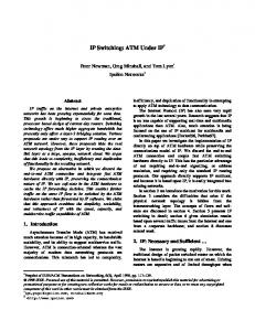
This model was used in the tool GPCAD [15]. To model submicron devices, more sophisticated and accurate models that are still compatible with geometric programming based design are needed. These models are a part of Barcelona PradoTM Synthesis Platform. These models are far more complex that the simple GP1 model and are very accurate. For example, in Figures 4- 5 we plot I/V measured data versus GP models for a TSMC 0 35µm process. We observe very little error over a large range of the modeling space.
3.5
3 Id in uA
�
4
2.5
2
1.5
1
0.5
0
0
0.2
0.4
0.6
0.8 1 Vds in V
1.2
1.4
1.6
1.8
Figure 5: Comparison of GP models to BSIM models for a transistor of W � 31 75µm, L � 1 35µm in a 0 35µm process
I−V curves for TSMC0.35 W=8um, L=0.35um 0.9
0.8
charge pump to PLL jitter is written in posynomial form. This hierarchical formulation results in a modular description for the geometric program. It results in better maintainability of the implementation and enables re-use of code when implementing the method for different PLL topologies. For example, if we want to use a different charge-pump in the PLL only the much smaller charge-pump module of the code needs to be updated. In summary, the design methodology consists of the following steps:
0.7
Id in uA
0.6
0.5
0.4
0.3
0.2
0.1
0
0
0.2
0.4
0.6
0.8 1 Vds in V
1.2
1.4
1.6
1.8
Figure 4: Comparison of GP models to BSIM models for a transistor of W � 8µm, L � 0 35µm in a 0 35µm process
3.3 Circuit modeling Circuit behavior needs to modeled using a form also compatible with geometric programming. In [15] the authors describe how to model op-amp behavior, in [16] the authors show how to model RF circuit behavior and in [17] the authors show how to model multistage feedback amplifiers. The PLL architectures we modeled are shown in Figure 6 (clock generation) and Figure 7 (clock synchronization). The design constraints are formulated hierarchically. First, the design constraints of the sub-blocks of the PLL such as the chargepump and VCO are formulated as a function of their input/output specifications. For example, the output current mismatch of the charge-pump is formulated in posynomial form as a function of the transistor sizes and parameter values of the charge-pump. Second, the system level design constraints of the PLL are formulated in terms of the input/output specifications of the sub-blocks. For example, the contribution of the output current mismatch of the
1. Defining sub-blocks and corresponding input/output variables. The sub-blocks of a PLL include the phase/frequency detector, charge-pump, loop filter, voltage-controlled oscillator, and divider (see Figures 6 and 7). Each sub-block has a minimal number of defining input/output variables that are sufficient to describe the behaviour of the PLL and the interaction between sub-blocks. For example, the input/output variables of the PFD include power dissipation, area, reset time, up/down timing mismatch, and output rise/fall time. 2. Writing (posynomial) equations for input/output variables of sub-blocks in terms of component sizes. For analog subblocks this can be done using the methodology described in previous papers [15] or it can be done using other numerical fitting methods [23]. The focus of this paper is not to show the detailed modeling of the components but rather to explain how to expand the methology for higher level blocks. 3. Writing (posynomial) system level PLL design equations in terms of input/output variables of sub-blocks. At this step, the design constraints of the PLL are put in posynomial inequality form in terms of the input/output variables of the sub-blocks. This step and the previous step introduce a hierarchical methodology for writing PLL design equations in terms of the PLL component sizes. For example, the total power dissipation of the clock generation PLL is given by the sum of the power dissipations of its sub-blocks, i.e.,
PPLL �
PPFD � PCP � PCP � PVCO ��� PDCDIV � PDIV (2)
PSfrag replacements Divider �
M
clock in
Voltage controlled oscillator
Phase/frequency Charge pump detector Loop filter UP DN
Divider �
Divider �
N
P
Divider clock out PSfrag replacements
�
Q
Figure 6: Block diagram of Barcelona’s clock generation PLL application.
fout Divider Q clock
�
M
Voltage controlled oscillator
Phase/frequency Charge pump detector Loop filter UP DN
Divider �
Replica clock tree
Divider �
N
P
Clock tree
data
D
clk
Q
Figure 7: Block diagram of Barcelona’s clock deskew PLL application.
The power for each sub-block is one of its I/O variables and can in turn be expressed as a posynomial function of its design variables. Another simple additive top level spec is area. The total PLL area is the sum of the areas of each of its subcomponents. APLL �
APFD � PCP � ACP � AVCO ��� ADCDIV � ADIV (3)
The layout area of a component is another of the sub-block I/O variables. The area of a sub-block can be written as a posynomial of the design variables. Stability conditions for the PLL can be obtained by deriving posynomial constraints on the phase margin and gain margin from the loop gain expression of the PLL [24]. The loop gain of the PLL is given by �
T � s ���
� 1 � τ1 s � � 1 � τ3 s � e � std k m � s2 � 1 � τ2 s � � 1 � as � bs2 � cs3 � �
(4)
where k � kpd kcp klf kvco , m is the frequency division ratio of the frequency divider and duty cycle divider, � 1 � τ1 and � 1 � τ2 are the zero and pole of the LF, τ3 , a, b and c represent the transfer function of the VCO, and td is the delay of the PFD, frequency divider, duty cycle divider, clock tree, and VCO combined.
To compute the peak-to-peak jitter, cycle-to-cycle jitter and static phase error one must take into account all sources of jitter: phase noise in the oscillator, power supply noise, charge pump current mismatch, etc.Posynomial modeling of these characteristics at the circuit level is needed. 4. Formulate problem as geometric program and solve for component sizes using numerical algorithm. Once design constraints are put in posynomial form, the PLL design problem is cast as a geometric program and hence it can be readily solved using efficient numerical algorithms. 4 Practical design examples We have used Mir´oTM Clocking Engine to synthesize three phaselocked loops in the TSMC 0 18µm logic process. The user can define his PLL requirements, specify target process and circuit parameters such as input frequency and frequency multiplication factors, specifications on area, power, clock jitter, etc.All of the performance metrics for the PLL design have been accurately modeled using geometric programming. In Table 1 we show the design results of a clock synchronization PLL. Within three hours, Mir´oTM produced an optimal PLL design all the way from specifications to fully routed GDSII. The PLL was designed over three process corners: typical-typical,
Figure 8: Optimal tradeoff curve between minimum area and minimum power
Vdd � 1 8V , T � 25oC; slow-slow, Vdd � 1 6V , T � 75oC and fastfast, Vdd � 1 9V , T � 0oC. The goal in this design was to minimize power while meeting all the specifications shown in Table 1. Parameter Input reference frequency 1 (MHz) Input reference frequency 2 (MHz) VCO frequency 1 (MHz) VCO frequency 2 (MHz) Width (µm) Heigth (µm) Duty cycle Jitter (peak-to-peak) (ps) Jitter (cycle-to-cycle) (ps) Static phase error (ns) Power consumption (mW)
Spec. 9 27 384 1080 680 760 � 5 150 0.1 min
Synthesis 9 27 384 1080 572 751 � 1 91 3.6 0.1 8.25
Table 1: PLL A, specifications and synthesized results The designer can explore the design space by plotting optimal trade-off curves. These curves curves show how the objective function will trade-off with another specification. For example, in Figure 8, we show an area versus power tradeoff curve. This curve is obtaining by repeatedly solving the design problem (minimizing area) while varying power. The rest of specifications are set to the values given in Table 1. We see that (as expected) more power means less area. However, we can measure things that we do not know a priori. For example, increasing the power budget more than 10mW will not translate into a reduction on area; the reason is that there are other design specifications that are constraining the objective. In Figure 9 we plot the optimal tradeoff curve peak jitter versus power when the remaining specifications are set to the values given in Table 1. This curve allows us to measure exactly how jitter and power tradeoff. In Table 2 we show the design results of a clock generation PLL. This PLL is used in video applications. This PLL was designed over the same process corners as the previous PLL. In Table 3 we show the design and measured results for another clock generation PLL. This PLL is used in audio applications. Due to the large size of its components, the loop filter is implemented externally. This PLL was designed over the same process corners as the previous ones.
Figure 9: Optimal tradeoff curve between minimum peak-to-peak jitter and minimum power Parameter Input reference frequency 1 (MHz) Output frequency 1 (MHz) Output frequency 2 (MHz) Output frequency 3 (MHz) Area (mm2 ) Duty cycle Jitter (peak-to-peak) (ps) Jitter (cycle-to-cycle) (ps) Power consumption (mW)
Spec. 33 3.30 81.0 13.5 min � 5 300 80 3
Synthesis 33 3.30 81.0 13.5 0.589 � 1 240 40 3
Table 2: PLL B, specifications and synthesized results Parameter Input frequency 1 (MHz) Output frequency 1 (KHz) Output frequency 2 (MHz) Output frequency 3 (MHz) Area (µm2 ) Duty cycle Jitter (peak-to-peak) (ps) Jitter (cycle-to-cycle) (ps) Power consumption (mW)
Spec. 27 43.2 135.472 11.2896 min 5 400 100 10
Synthesis 27 43.2 135.4752 11.2896 348 1 240 40 3.5
Simulated 27 43.2 135.4752 11.2896 348 3.8
Measured 27 43.2 135.4752 11.2896 348 50 304 36.5 2.7
Table 3: PLL C, specifications, synthesized, simulated and measured results We note the close agreement between measured and predicted results. We guaranteed robustness of our designs to process variation by requiring that all constraints and specifications hold over all process corners. In other words, we replicated each constraint for each process corner. This method is more comprehensive than traditional techniques which use only a few critical parameters and circuit design intuition to ensure robustness over process variations. Table 4 shows the jitter performance over supply and temperature variations. 5 Conclusions We have shown some design results and experimental verification of phase-locked loops designed using geometric programming techniques. The most important point is that the PLL we built and tested was designed in a completely automated way, directly
Vd 1.6V 1.8V 2.0V
Jitter, T=-20o 1σ p-p 28.4 286 36.5 304 35.3 294
Jitter, T=25o 1σ p-p 32.1 265 30.3 284 31.2 339
Jitter, T=75o 1σ p-p 27.8 229 28.0 229 28.1 231
References [1] B. Martin. Electronic design automation. IEEE Spectrum, 36(1):57–61, January 1999. [2] Cahners In Stat. Miscellaneous industry reports.
Table 4: Jitter measurements over temperature and voltage conditions
[3] P. Gray. Analog ICs in the submicron era: trends and perspectives. In Proceedings IEEE International Electron Devices Meeting, pages 5–9, 1987.
from the specifications. No hand-tuning or designer tweaking of the designs was carried out before fabricating; the fabricated circuits directly used the designs obtained from the Barcelona Mir´oTM Clocking Engine. The use of synthesizable custom IP offers the advantages of custom designed blocks (since blocks are custom designed to meet a set of requirements) and the advantages of hard IP blocks (since design time is very short).
[4] Neolinear. Neolinear tunes analog circuit synthesis with the release of Neocircuit V1.1. Press release, november 2001. www.neolinear.com/news/index.html. [5] Analog Design Automation. ADA unwraps fresh approach to analog, mixed-signal and high performance digital integrated circuit design. Press release, april 2002. www.analogsynthesis.com. [6] Antrim. Antrim Design Systems launches platform for specdriven mixed-signal design. Press release, september 2000. www.antrim.com/news events/index.htm. [7] Taiwan Semiconductor Manufacturing Company, 2002. www.tsmc.com. [8] United Microelectronics www.umc.com.
Corporation,
2002.
[9] Barcelona Design. Barcelona design unveils revolutionary analog circuit solution. Press release, april 2002. www.barcelonadesign.com. [10] The Mathworks. Matlab 6.1. http://www.mathworks.com/products/matlab/. [11] Microsoft. Excel 2002. http://www.microsoft.com/office/excel/default.asp. [12] E. S. Ochotta, R. A. Rutenbar, and L. R. Carley. Synthesis of high-performance analog circuits in ASTRX/OBLX. IEEE Transactions on Computer-Aided Design, 15:273–293, March 1996. [13] W. Nye, D. C. Riley, A. Sangiovanni-Vincentelli, and A. L. Tits. DELIGHT.SPICE: An optimization-based system for the design of integrated circuits. IEEE Transactions on Computer-Aided Design, 7:501–518, April 1988. [14] M. Krasnicki, R. Phelps, R. A. Rutenbar, and L. R. Carley. Maelstrom: Efficient simulation-based synthesis for custom analog cells. In Proceedings of the 31st Annual Design Automation Conference, pages 945–950, 1999. [15] M. Hershenson, S. Boyd, and T. H. Lee. GPCAD: A tool for CMOS op-amp synthesis. In Proceedings of the IEEE/ACM International Conference on Computer Aided Design, San Jose, CA, November 1998. [16] M. Hershenson, S. Mohan, S. Boyd, and T. H. Lee. Optimization of inductor circuits via geometric programming. In submitted to 36th IEEE/ACM Design Automation Conference, 1999. http://www.stanford.edu/˜boyd. [17] J. L. Dawson, S. Boyd, M. Hershenson, and T. H. Lee. Optimal allocation of local feedback in multistage amplifiers via geometric programming. IEEE Transactions on Circuits and Systems I, 48(1):1–11, January 2001. [18] R. J. Duffin, E. L. Peterson, and C. Zener. Geometric Programming — Theory and Applications. Wiley, 1967.
[19] J. P. Fishburn and A. E. Dunlop. TILOS: A polynomial programming approach to transistor sizing. In Proceedings IEEE International Conference on Computer-Aided Design, pages 326–328, 1985. [20] S. Boyd and L. Vandenberghe. Introduction to convex optimization with engineering applications. Course Notes, 1997. http://wwwleland.stanford.edu/class/ee364/. [21] K. O. Kortanek, X. Xu, and Y. Ye. An infeasible interior-point algorithm for solving primal and dual geometric programs. Math Programming, 76:155–181, 1996. [22] M. Hershenson, S. Boyd, and T. H. Lee. GPCAD: A tool for CMOS op-amp synthesis. In Proceedings of the 1998 IEEE/ACM International Conference on Computer Aided Design, November 1998. [23] W. Daems, G. Gielen, and W. Sansen. Simulation-based automatic generation of signomial and posynomial performance models for analog integrated circuit sizing. In IEEE/ACM International Conference on Computer-Aided Design, pages 70–74, San Jose, CA, November 2001. [24] T. H. Lee. The design of CMOS radio-frequency integrated circuits. Cambridge University Press, 1998.