A Synthesizable IP Core for WiMedia 1.5 UWB LDPC Code Decoding Matthias Alles and Norbert Wehn
Friedbert Berens
Microelectronic Systems Design Research Group University of Kaiserslautern 67663 Kaiserslautern, Germany Email: {alles, wehn}@eit.uni-kl.de
FBConsulting S.`a r.l. 21, Route de Luxembourg 6633 Wasserbillig, Luxembourg Email:
[email protected]
Abstract—The upcoming WiMedia 1.5 standard for UltraWideband (UWB) supports payload throughputs of more than 1 Gbit/s. It features Low-Density Parity Check (LDPC) codes as coding scheme for the high data rate modes. LDPC decoder design for this standard is a very challenging task, since it has to offer high throughputs, low latency, excellent error correction capabilities, and furthermore flexibility. LDPC decoding is an iterative process. A huge amount of data has to be exchanged between processing units in each iteration. A high parallelism of the decoder is essential in order to meet the tight requirements of the WiMedia standard. In this paper we present to the best of our knowledge the first implementation of an LDPC decoder for WiMedia 1.5. The decoder uses an increased parallelism compared to conventional decoder architectures, which enables high payload throughputs of more than 1 Gbit/s for a small block size of 1200 bits. Detailed synthesis and communications performance results are shown.
I. I NTRODUCTION Channel coding is a vital part of digital data transmission in order to ensure the Quality of Service (QoS) and to reduce power consumption. Low-Density Parity Check (LDPC) codes [1] belong to the best channel codes known today. Because of their iterative decoding scheme they allow for a near-optimum performance close to the Shannon limit. This property led to the inclusion of LDPC codes into a wide range of communication standards, such as WiFi, WiMax, and DVB-S2/T2. Recently, LDPC codes were adopted from the WiMedia alliance for the high data rate modes (up to 1024 Mbit/s payload) of the WiMedia UWB standard [2]. Investigations have shown the superiority of LDPC codes over the previously used convolutional codes in the context of OFDM-based UWB systems [3][4]. In comparison they showed a high coding gain of up to 3 dB. LDPC decoding is an iterative process where a huge amount of messages are exchanged between two types of nodes (variable and check nodes). An LDPC decoder becomes very efficient when employing an architecture-aware code design [5]. The parity check matrices of these codes are composed of cyclically shifted identity matrices (called submatrices hereafter). They allow for the exploitation of the inherent parallelism of the LDPC decoding algorithm yielding high decoder throughputs. Using very sparse parity check matrices as proposed in [3] decreases the decoder complexity even further.
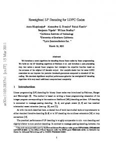
Fig. 1.
WiMedia UWB simulation chain
In the new WiMedia standard, the decoder has to satisfy tight constraints regarding throughput, latency, and flexibility, making the decoder design very challenging. An air data rate of up to 1.41 Gbps has to be supported at a moderate clock frequency of 264 MHz and small codeword sizes (1200 or 1320 bits). Furthermore, the latency of the decoding process has to be less than 0.9375 µs. When compared to traditional LDPC decoders (e.g., [3][4][6][7]) an entire redesign of the decoder architecture is mandatory in order to meet the tight constraints. In state-of-the-art architectures one submatrix is processed per clock cycle. For a WiMedia decoder this is not sufficient. Instead three submatrices need to be processed. It is the first standard that relies on such a decoder architecture. An approach to resolve this issue was presented in [8]. However, the authors used fully parallel check node processing units which is prohibitive for high check node degrees as used in the WiMedia standards. Furthermore, they did not show the implementation complexity. In this paper we present to the best of our knowledge the first implementation of an LDPC decoder for the WiMedia UWB standard. The decoder employs partly parallel check node processing units in order to process multiple submatrices per clock cycles. The paper presents the decoder architecture along with synthesis results in a 65 nm technology and communications performance simulations. II. W I M EDIA UWB S YSTEM M ODEL The WiMedia UWB standard is based on a multiband OFDM air interface with and without frequency hopping. The overall US UWB band ranging from 3.1 GHz to 10.6 GHz is split into 14 subbands using 528 MHz of bandwidth with 128 OFDM subcarriers. The subbands are grouped to form five band groups. Four of them contain three subbands and one consists of two subbands. In this paper we will focus on the first band group ranging from 3.1 GHz to 4.8 GHz. In order
Channel Model CM1 CM2 CM3 CM4
Range 0-4 m 0-4 m 4-10 m 4-10 m
RMS Delay 5 ns 8 ns 14 ns 26 ns
Average No. of Paths 21.4 37.2 62.7 122.8
Transmission Condition Line-of-Sight (LoS) Non LoS Non LoS Extreme Non LoS
TABLE I IEEE C HANNEL MODELS FOR UWB Parameter Payload data rate Data carriers FFT size Symbol Duration Channel Coding Carrier Modulation
Value 53 Mbit/s to 1024 Mbit/s 100 128 points 312.5 ns (incl. Guard) CC with K = 7; LDPC Codes QPSK, DCM, 16QAM
TABLE II W I M EDIA P HYSICAL LAYER PARAMETERS
to evaluate the communications performance of the WiMedia UWB standard a SystemC based simulation chain has been implemented. The basic structure of the simulation chain is depicted in Figure 1. The current WiMedia system uses standard convolutional coding. In WiMedia 1.5 LDPC codes were adopted for the high data rates (≥ 640 Mbit/s payload). After channel coding the coded data stream is interleaved and then mapped onto QPSK symbols for the lower data rates and DCM symbols for the medium data rates ranging from 300 Mbit/s to 480 Mbit/s. For the high data rates 16QAM is used. These symbols are then used in the OFDM modulator to generate the OFDM symbols to be transmitted over the channel. The channel models used correspond to the IEEE 802.15.3a channels CM1 to CM4. The main characteristics of these models are depicted in Table I. In the receiver the signal is demodulated and equalized deploying ideal channel estimation. The resulting demapped and deinterleaved soft-information is then processed by the channel decoder which is either a Viterbi decoder or an LDPC decoder. The WiMedia physical layer parameters are depicted in Table II. III. LDPC C ODES LDPC codes [1] are linear block codes defined by a sparse parity check matrix H of size M × N , see Figure 2a). For binary LDPC codes a valid codeword ~x has to satisfy H~xT = ~0 in a modulo-2 arithmetic. A column in H is associated to a codeword bit, a row corresponds to a parity check. A non-zero element in a row means that the corresponding bit contributes to this parity check. Typically, 2% or less of the elements of H are non-zero. The complete code can be best visualized by a Tanner graph, a graphical representation of the associations between code bits and parity checks. Each column of H corresponds to a variable node (VN) and represents one code bit, each row of H corresponds to a check node (CN) and represents one parity check, respectively. Edges connect variable and check nodes according to the non-zero elements of the parity check
Fig. 2.
Tanner graph of an irregular LDPC code
matrix. Figure 2b) shows the corresponding Tanner graph to the parity check matrix in Figure 2a) of an LDPC code with N = 7 variable nodes and M = 3 check nodes. The resulting code rate is R = (N − M )/N = 4/7. A. LDPC Decoding LDPC codes can be decoded using the Sum-Product algorithm (SPA) [1]. Soft information is exchanged iteratively between variable and check nodes. To reduce the implementation complexity the SPA is transformed into the logarithmic domain. Decoding works as follows: The variable node n is initialized with the corresponding log-likelihood ratio (LLR) of the received bit λch n . Next, messages are propagated from the variable nodes to the check nodes via the edges of the Tanner graph. For the first iteration the messages sent by the variable node n via its edges to the connected check nodes m. λn→m = λch n . The check node m computes new messages for the variable nodes. Due to the high implementation complexity of the optimal belief propagation algorithm, suboptimal algorithms are used for the check node implementation. We use the normalized Min-Sum algorithm [9] where only the two smallest magnitudes are used: Y (1) λm→n = α × sgn (λn′ →m ) n′ ∈N (m)\n
×
min
n′ ∈N (m)\n
(|λn′ →m |) ,
with N (m) the set of variable nodes connected to the check node m. When using the extrinsic scaling factor α, a communications performance close to the optimal algorithm is achievable. Typically, α is chosen as 0.75 or 0.875, since these values are easy to implement. Then, the variable nodes compute an overall estimation of the decoded bit (a posteriori probability, APP) by adding up the extrinsic information of all connected check nodes to the channel value: X Λn = λch λm′ →n , (2) n + m′ ∈M(n)
with M(n) the set of check nodes connected to the variable node n. The sign of Λn can be understood as the hard decision
0
Block Size N 1200 1200 1200 1200 1320 1320 1320 1320
24 48
Check Nodes
72 96 120 144 168 192 216 240
Code Rate R 1/2 5/8 3/4 4/5 5/11 25/44 15/22 8/11
Edges
P
3510 3720 3600 3510 4320 4770 4650 4650
30 30 30 30 30 30 30 30
Variable Node Degrees 2,3,4 2,3,4 2,3,4 2,3,4 2,3,4,5 2,3,4,5 2,3,4 2,3,4
Check Node Degrees 5,6 8,9 12 12,15 5,6 8,9 7,8,9,11,12 7,9,11,12,15
264 288 0
24 48 72 96 120 144 168 192 216 240 264 288 312 336 360 384 408 432 456 480 504 528 552 576
Variable Nodes
Fig. 3.
TABLE III W I M EDIA LDPC CODE PARAMETERS
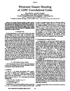
A parity check matrix of the WiMAX code with P = 24.
on the decoded bit. New messages λn→m are then computed following the extrinsic principle: X λn→m = λch λm′ →n = Λn − λm→n . (3) n + m′ ∈M(n)\m
The decoding process is stopped after a maximum number of iterations or earlier if the parity check is satisfied. B. Layered Decoding Updating the variable and check nodes can be done with a two-phase scheduling: In the first phase all variable nodes are updated, in the second phase all check nodes, respectively. To improve the communications performance for a given number of iterations turbo decoding message passing (TDMP) [5], which is also known as layered decoding, shuffled decoding or Gauss-Seidel iterations, is used. The idea is to take intermediate results of the calculations into account still in the same iteration. Consider we are processing one check node. After computing new LLRs, they are sent back to the connected variable nodes immediately. These variable nodes update their outgoing edges, such that the other check nodes connected to these variable nodes will receive already updated results. With this technique it is possible to reduce the number of iterations by up to 50 % at a fixed communications performance. The achieved gain in convergence speed can thus be used to reduce the latency or to increase the throughput of the decoding process (valid for software as well as hardware decoders). C. Structured LDPC Codes A random connectivity between variable and check nodes poses big challenges for an efficient hardware implementation. Complex connectivity networks become mandatory to allow for a flexible and parallel message exchange, resolving occurring memory access conflicts. Thus, LDPC codes defined by standards are based on so called structured LDPC codes [10]. The matrices of these codes are composed of cyclically shifted identity matrices of size P × P , see Figure 3. These codes allow for an efficient implementation of the connectivity between up to P variable and P check nodes. Memory access conflicts are avoided and a low complexity logarithmic barrel shifter is sufficient as connectivity network for a given P . Furthermore, storing the parity check matrix is simplified. Only the positions of the cyclically shifted identity matrices and the corresponding shift value have to
be stored. In Figure 3 these pairs for the check nodes 0 to 23 are (a, s) = {(1, 23), (2, 18), (8, 13), (9, 20), (12, 1), (13, 0)}, with a addressing the set of variable nodes and s the shift offset. D. WiMedia LDPC Codes The WiMedia matrices are structured ones with P = 30 and look very much the same as in the WiMax standard. At the moment they are still under non-disclosure. In the WiMedia standard, eight LDPC codes are provided, see Table III. Two block lengths (N = 1200, N = 1320) are defined, each offering four different code rates. As proposed in [3], the matrices are very sparse and only about 1% of the matrix entries are non-zero. Due to the high sparseness the decoder complexity is reduced and the decoding process is accelerated, since less edges have to be processed by the decoder. The high block length is optional and obtained by encoding a full 1200 bit codeword a second time with a code rate of 10/11. The 120 additional parity bits are transmitted via the guard carriers. IV. D ECODER A RCHITECTURE The implementation of LDPC decoders is either done in a fully parallel or partly parallel way. Fully parallel architectures instantiate all nodes of the Tanner graph. However, the large area, routing congestions and the lack of flexibility make this approach prohibitive [11]. Partly parallel architectures become mandatory where only a subset of VNs and CNs is instantiated through functional units (FU). The nodes of the Tanner graph are processed in a time multiplexed way on the FUs. Messages and APP values are stored in RAMs and accessed when needed by the FUs. A permutation network has to be used, that is capable to establish the correct connections between the FUs. Structured LDPC codes allow to replace complicated flexible networks by a low complex logarithmic barrel shifter with P inputs [10]. In state-of-the-art layered LDPC decoders, one submatrix (equal to P edges) is processed per clock cycle. This corresponds to serial working FUs that are capable to read/write one edge per clock cycle. In order to obtain high throughputs, P can be increased when designing a code. But increasing P is a trade-off between block length and communications performance. A high P at a low block length will result in a poor communications performance, due to the low degree of freedom when designing the code (the parity check matrix is composed of only a few submatrices then). Thus, a high
Fig. 5. Parity check matrix storage of WiMax code for decoder architecture with a) one slot b) three slots
Fig. 4.
Layered decoder architecture with partly parallel check nodes
P requires a large block length in order to obtain reasonable performance. For the WiMedia standard, however, the block length is fixed to 1200 bits because of the given framing structure. Due to this small block size it is not possible to increase P much beyond 30 by code design without sacrificing communications performance. Instead, the high throughput and the low latency constraints of WiMedia make the processing of multiple submatrices per clock cycles necessary. Figure 4 shows our WiMedia layered decoder architecture. The decoder consists of three slots, each capable of processing one submatrix (= 30 edges for WiMedia) per clock cycle. No explicit FUs for the variable nodes exist in the decoder. Instead the variable node operations according to Equation 2 and Equation 3 are processed in the 30 check node blocks (CNBs). The check node FUs (CFUs) contain the check node functionality, i.e., they perform the minimum search and the parity check. In our decoder, each CNB is capable to read and write three edges per clock cycle, while each edge stems from a different slot. Thus, the decoder allows for the processing of 90 edges per clock cycle. This parallelism yields the high throughput and low latency required, despite the low codeword and submatrix sizes. The minimum search within the CFU is performed according to [12]. Each slot holds one third of the variable node estimations Λn in its APP RAM, with P = 30 APP values per address. Slot 0 stores the 3 ∗ ith submatrix columns of the parity check matrix, i.e., it holds the APP information Λ0 to Λ29 at address 0, Λ90 to Λ119 at address 1, and so on. Slot 1 stores the (3 ∗ i + 1)th submatrix columns of the parity check matrix, i.e., it holds the APP information Λ30 to Λ59 , Λ120 to Λ149 , etc. Finally, slot 2 holds the rest of the APP information, i.e., the (3 ∗ i + 2)th submatrix columns. By addressing the APP RAM and shifting the output into the appropriate order, each CNB receives the correct APP information. Each slot has own address and permutation RAMs to store its portion of the parity check matrix. The content of these RAMs can be directly derived from the parity check matrix, as shown in Figure 3. Figure 5a) shows the address and shift vectors for the WiMax code for a decoder architecture
that consists of a single slot. At each address of the address and permutation RAM the position and the shift value for a single submatrix is stored. The horizontal lines indicate the beginning/end of a check node. In Figure 5b) the same code is processed on the proposed architecture with three slots. Taking the address in Figure 5a) modulo three gives the slot where this submatrix will be processed. Finally, dividing this address by three will give the new address for the target slot. The permutation values are not affected by this transformation. Using three slots instead of a single one, obviously leads to a significant acceleration of the decoding process. For the first check node group, only two instead of six clock cycles are necessary for reading the APP information. In case the memory accesses are not equally distributed to the slots (e.g., the check node degree is not divisible by three), the address vector is filled up with -1, see slot 0. For the decoder this means not to access the APP RAMs and to insert a nooperation cycle for this slot. The WiMedia codes were designed with respect to a stallfree decoder architecture. In Figure 5b), which shows the WiMax code, the decoder will have to stall between the first two check nodes. The reason is that for slot 1 both check nodes access the APP RAM at address 0. The second read access, however, must not be executed before the first check node has written back its updated information to the APP RAM. Due to the delay of several clock cycles while decoding, stall cycles have to be introduced in this case. For WiMedia, the check node processing can be scheduled in such a way that accessing the same APP information only happens, when the result was written back before. No stall cycles have to be introduced, which results in a high utilization of the functional units. V. R ESULTS A. Implementation The presented WiMedia LDPC decoder was implemented in synthesizable VHDL code and synthesized in a 65 nm CMOS low power technology. The following constraints are satisfied: • Code rate flexibility • Codeword size flexibility (1200 bits and 1320 bits) • Clock frequency of 264 MHz • Air throughput of 1.28 Gbps for short blocks • Air throughput of 1.41 Gbps for long blocks
Code Rate R 1/2 5/8 3/4 4/5 5/11 25/44 15/22 8/11
No. of Iter. 5 5 5 5 4 3 3 3
Clock Cycles 219 247 226 227 211 193 194 207
Latency / µs 0.83 0.93 0.86 0.86 0.80 0.73 0.74 0.78
Throughput / Gbps Air Payload 1.44 0.72 1.28 0.80 1.40 1.05 1.40 1.12 1.65 0.75 1.80 1.02 1.79 1.22 1.68 1.22
TABLE IV T HROUGHPUT RESULTS FOR 264 MH Z CLOCK FREQUENCY LDPC Code WiMedia 1.5 No. of Slots 3 Slot Parallelism 30 Input Quantization 5 bit APP Quantization 7 bit Algorithm MinSum, ESF=0.875 Throughput see Table IV Comm. Performance see Figure 6 Area[mm2 ] 65nm@264MHz CNB Logic 0.08 Controller Logic 0.02 Networks 0.02 APP RAMs 0.18 CNB RAMs 0.16 Code Vectors 0.04 Overall Logic 0.12 (23.5%) Overall Memory 0.39 (76.5%) Overall Area 0.51 (100%) TABLE V S YNTHESIS RESULTS FOR THE W I M EDIA 1.5 LDPC DECODER
Latency less than 0.9375 µs (247 clock cycles) Table IV gives the obtained throughput and latency results for the six codes defined by the standard. Double buffering is applied in order to hide the input interface latency. Payload throughputs of more than 1 Gbps are obtained. The core was synthesized in a 65 nm low power technology, see Table V. Overall, the decoder takes 0.51 mm2 after synthesis. 76.5% (0.39 mm2 ) are caused by the memories and only 23.5% (0.12 mm2 ) come from logic. The memory domination is caused by its disadvantageous aspect ratios. E.g., the APP RAMs are only 16 entries deep but 210 bit wide, resulting in inefficient bit densities and yielding the high area. •
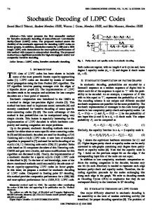
B. Communications Performance Figure 6 shows the communications performance of the short LDPC codes. The results were obtained using the UWB simulation chain as shown in Figure 1 with a CM1 channel and a bit-accurate LDPC decoder model. For comparison reasons the performance of a rate 3/4 convolutional code (64 states) is also shown. Compared to the corresponding LDPC code a coding gain of 4 dB (PER 10−1 ) to 6 dB (PER 10−3 ) can be observed. VI. C ONCLUSION In this paper we presented to the best of our knowledge the first implementation of a WiMedia 1.5 UWB LDPC decoder. The decoder allows for payload throughputs beyond 1 Gbit/s
WiMedia LDPC Codes, 1200 bits, CM1, 16−QAM
0
10
LDPC, R=1/2, 5 iterations LDPC, R=5/8, 5 iterations LDPC, R=3/4, 5 iterations LDPC, R=4/5, 5 iterations CC, R=3/4
−1
10
PER
Block Size N 1200 1200 1200 1200 1320 1320 1320 1320
−2
10
−3
10
14
16
18
20
22
24
26
28
EB/N0 [dB]
Fig. 6.
Performance results for WiMedia LDPC codes
despite the small block length of 1200 bits and the moderate clock frequency of 264 MHz. It offers all the flexibility required by the standard. The overall area of the decoder is 0.51 mm2 after synthesis in a 65 nm low power CMOS technology. It is dominated by the memories (76.5%). R EFERENCES [1] R. G. Gallager, “Low-Density Parity-Check Codes,” IRE Transactions on Information Theory, vol. 8, no. 1, pp. 21–28, January 1962. [2] Standard ECMA-368, “High Rate Ultra Wideband PHY and MAC Standard.” [Online]. Available: http://www.ecma-international.org [3] T. Brack, F. Kienle, T. Lehnigk-Emden, M. Alles, N. Wehn, and F. Berens, “Enhanced Channel Coding for OFDM-based UWB Systems,” in Proc. International Conference on Ultra-Wideband (ICUWB 2006), Waltham, Massachusetts, Sep. 2006, pp. 255–260. [4] T. Brack, M. Alles, T. Lehnigk-Emden, F. Kienle, N. Wehn, F. Berens, and A. Ruegg, “A Survey on LDPC Codes and Decoders for OFDMbased UWB Systems,” in Proc. 56th Vehicular Technology Conference (VTC Spring ’07), Dublin, Ireland, Apr. 2007. [5] M. Mansour and N. Shanbhag, “Architecture-Aware Low-Density Parity-Check Codes,” in Proc. 2003 IEEE International Symposium on Circuits and Systems (ISCAS ’03), Bangkok, Thailand, May 2003. [6] G. Gentile, M. Rovini, and L. Fanucci, “Low-Complexity Architectures of a Decoder for IEEE 802.16e LDPC Codes,” in Digital System Design Architectures, Methods and Tools, 2007. DSD 2007. 10th Euromicro Conference on, L¨ubeck, Germany, Aug. 2007, pp. 369–375. [7] P. Urard, L. Paumier, V. Heinrich, N. Raina, and N. Chawla, “A 360mW 105Mb/s DVB-S2 Compliant Codec based on 64800b LDPC and BCH Codes enabling Satellite-Transmission Portable Devices,” in Proc. Digest of Technical Papers. IEEE International Solid-State Circuits Conference ISSCC 2008, 3–7 Feb. 2008, pp. 310–311. [8] S. Kim, G. E. Sobelman, and H. Lee, “Flexible LDPC Decoder Architecture for High-Throughput Applications,” in Proc. IEEE Asia Pacific Conference on Circuits and Systems APCCAS 2008, Nov. 2008, pp. 45– 48. [9] J. Chen, A. Dholakia, E. Eleftheriou, M. P. C. Fossorier, and X.-Y. Hu, “Reduced-Complexity Decoding of LDPC Codes,” IEEE Transactions on Communications, vol. 53, no. 8, pp. 1288–1299, Aug. 2005. [10] E. Boutillon, J. Castura, and F. Kschischang, “Decoder-first code design,” in Proc. 2nd International Symposium on Turbo Codes & Related Topics, Brest, France, Sep. 2000, pp. 459–462. [11] A. Blanksby and C. J. Howland, “A 690-mW 1-Gb/s, Rate-1/2 LowDensity Parity-Check Code Decoder,” IEEE Journal of Solid-State Circuits, vol. 37, no. 3, pp. 404–412, Mar. 2002. [12] X.-Y. Shih, C.-Z. Zhan, C.-H. Lin, and A.-Y. Wu, “An 8.29 mm 52 mW Multi-Mode LDPC Decoder Design for Mobile WiMAX System in 0.13 & CMOS Process,” IEEE Journal of Solid-State Circuits, vol. 43, no. 3, pp. 672–683, March 2008.