Dec 2, 2013 - By introducing new waveforms, the project fosters a re-design of ... performance evaluations of the non-orthogonal waveforms (together with key radio resource ... Particular challenges that need to be faced in 5G systems are ...
47th Annual Asilomar Conference on Signals, Systems, and Computers
System-Level Interfaces and Performance Evaluation Methodology for 5G Physical Layer Based on Non-orthogonal Waveforms G ERHARD W UNDER1 , M ARTIN K ASPARICK1 , S TEPHAN TEN B RINK2 , F RANK S CHAICH3 , T HORSTEN W ILD3 , Y EJIAN C HEN3 , I VAN G ASPAR4 , N ICOLA M ICHAILOW4 , G ERHARD F ETTWEIS4 , D IMITRI K TENAS5 , N ICOLAS C ASSIAU5 , M ARCIN D RYJANSKI6 , K AMIL S OROKOSZ6 , S LAWOMIR P IETRZYK6 , AND B ERTALAN E GED7 1
Fraunhofer Heinrich Hertz Institute, Berlin, Germany 2 University of Stuttgart, Germany 3 Bell-Labs, Alcatel-Lucent, Stuttgart, Germany 4 TUD (Technische Universit¨at Dresden)–Vodafone Chair Mobile Communications Systems, Dresden, Germany 5 Commissariat a` l’´energie atomique et aux e´ nergies alternatives (CEA-LETI), Grenoble, France 6 IS-Wireless, Warsaw, Poland 7 Systems Engineering Center of Excellence, National Instruments, Budapest, Hungary
December 2, 2013 Abstract 5GNOW is a European collaborative research project questioning the design targets of LTE and LTE-Advanced, in particular the obedience to strict synchronism and orthogonality. By introducing new waveforms, the project fosters a re-design of physical and partially MAC layer to support heterogeneous traffic (high rate, sporadic access, carrier aggregation). For system level performance evaluations of the non-orthogonal waveforms (together with key radio resource management algorithms) an abstract view of the physical layer with analytical models going beyond standard OFDM performance evaluation (e.g. due to additional dependencies between resource blocks) is needed. In this paper, elements of a system level simulation platform are developed, which provide necessary abstractions and sufficient accuracy to capture the essential physical layer behavior at a reasonable computational complexity.
5GNOW is a European research project supported by the European commission within FP7 ICT Call 8. www.5gnow.eu
I. I NTRODUCTION The fifth generation (5G) of cellular communication systems is on the way. It is commonly believed that 5G will enable a multitude of intriguing applications, such as the Internet of Things (IoT), the Tactile Internet, Gigabit connectivity and many more. Particular challenges that need to be faced in 5G systems are fragmented spectrum and spectrum agility. It is unlikely that these challenges can be met using OFDM, therefore highly flexible and robust new waveforms are required. In particular the design principles of the current LTE-A physical (PHY) layer, i.e. synchronism and orthogonality, will have to be relaxed. In the 5GNOW project [1] several candidate waveforms are proposed, such as Filter Banks Multi-Carrier (FBMC), Universal Filtered Multi-Carrier (UFMC), and Generalized Frequency Division Multiplexing (GFDM). Many of them have been evaluated on link level so far, however, simulations on system level are also needed to get further insight regarding the suitability of the particular waveforms for 5G systems and applications. In system level simulations the PHY layer including all signal processing cannot be explicitly simulated due to prohibitive complexity. For this reason PHY-layer abstractions for the new waveforms are needed which must have a sophisticated accuracy to capture all the essential characteristics of the PHY layer processes. In this paper we exemplary focus on FBMC and take first steps towards link-to-system interface design for new non-orthogonal waveforms. II. P RELIMINARIES A. FBMC Waveform The FBMC waveform with its spectrally well shaped prototype filters and overlapped time symbols has some inherent features which makes it a natural choice for some of the anticipated 5G application scenarios. First of all it does not require a cyclic prefix and has an almost perfect separation of frequency subbands without the need for strict synchronization. Consequently its properties make it especially suited for fragmented spectrum and Coordinated Multi Point (CoMP) Transmission/Reception. In this paper we use the following prototype filter for FBMC, whose time and frequency response is depicted in Figure 1 for a number of subcarriers Nc = 512 and an overlapping factor K = 4, also known as PHYDYAS filter [2] � � K−1 X 2πk k (t + 1) . (1) h(t) = P0 + 2 (−1) Pk cos KNc k=1 i h p The coefficients of the prototype filter for an overlapping factor K = 4 are given by P0:3 = 1, 0.97195983, √12 , 1 − P12 . In Figure 1 it can be observed that a significant overlap between adjacent carriers exists, which is usually compensated by using Offset QAM (OQAM) modulation. For further details please refer to [2].
Fig. 1.
Time and frequency response of FBMC prototype filter. Subcarrier 0 (blue) and 1 (red).
In general FBMC is a well-established waveform in the literature, however evaluations on system-level are needed, which require a suitable link-to-system interface.
B. PHY Abstraction Techniques Issues such as multiplexing, channel coding and modulation, signal processing, equalization and detection, etc., are usually investigated using link level simulations. It would entail a tremendous overhead if this was to be carried out in system-level simulations which typically consider multiple users and cells and where the focus lies on scheduling, interference, mobility, etc. In order to avoid having to carry out actual signal processing, in system level simulations usually a link-to-system interface comprising a suitable PHY layer abstraction is used. The goal of this PHY layer abstraction is essentially to obtain a block error rate (BLER) for a transport block (given particular subcarrier channel realizations) without having to carry out real signal processing. This is usually implemented in form of a look-up table where packet or block error rates are given for a certain effective quality measure, often the SINR, taking into account modulation and coding, power control, resource allocation, HARQ, etc. Using the SINR as quality measure, a crucial element of the PHY abstraction is the Effective SINR Mapping (ESM). In order to obtain a BLER a so-called effective SINR for a whole transport block of a given user is needed, since in complex systems simply averaging the SINRs does not provide a satisfying accuracy of the interface. This comes with a number of challenges. First, the transport block of bits is spread across (possibly non-orthogonal) subcarriers and each individual subcarrier may experience different SNIR. Second, interferences from different base stations may have different influence on different subcarriers. Also, each user may use different parts of the available bandwidth and the BLER for each of these parts may be calculated separately (since the user may use different modulation and coding schemes (MCS) on its allocated resources). A widely used concept is that of an effective SINR mapping function I(·) [3]. The overall procedure can be summarized in the form (for simplicity omitting optional parameters for scaling towards different MCS and code block sizes) ! L 1X −1 I(γl ) . (2) γef f = I L l=1
The value of the mapping is calculated for the quality measure γl on every particular resource element l of the transmission. Subsequently all those values are averaged and eventually an effective quality measure γef f for the overall transport block can be obtained by taking the inverse mapping of the averaged quantity. As mentioned before, the SINR is frequently used as quality measure and typical candidate functions can be for example linear, logarithmic, exponential, or mutual information functions [3]. Often, in system simulations transmitters and receivers are assumed to be perfectly synchronized. However, time and frequency offsets can be a major source of performance degradation in multicarrier systems. Therefore it is desired to directly incorporate such offsets into the abstraction. III. T OWARDS PHY-A BSTRACTIONS FOR N ON -O RTHOGONAL WAVEFORMS : FBMC E XAMPLE To evaluate the system-level performance of FBMC, a PHY abstraction that can deal with non-orthogonal waveforms and synchronization errors is needed. To find a suitable interface the following challenges, partly already discussed in the previous section, have to be resolved. First, a suitable quality measure function that incorporates the effects due to non-orthogonality needs to be found. Second, a suitable effective SINR mapping function according to (2) needs to be defined. Further, we need to derive means to incorporate temporal-spectral asynchronisms, and eventually we need to define a suitable frame structure and generate the AWGN - SNR/BLER tables. We will elaborate on each of these steps in the following. A. Link-to-System Interface for FBMC The SINR measure, which is usually applied in the evaluation of OFDMA systems, cannot capture the mutual dependencies between subcarriers of non-orthogonal multicarrier schemes. In our simulations we resolve to using the SNIDR model, as proposed in [4], where the “D” stands for the residual distortion. The SNIDR on subcarrier l is defined as [4] SNIDRl =
Ps . P i + Pn + Pd
Thereby Ps , Pi , and Pn denote the signal power, interference power, and noise power, respectively. Pd denotes the residual distortion power and can be calculated as 2Ps H 0 (ω) Pd (l) = 3 k l kCf . L Hl (ω) Let Hl (ω) and Hl0 (ω) be the channel frequency response and its derivative, respectively, both evaluated at the lth subcarrier. Hl0 (ω) wl x2 1 −x2 x2 1 0 In a Rayleigh fading channel, with H(x) = σx2 exp( 2σ 2 ) and H (x) = σ 2 exp( 2σ 2 )(1 − σ 2 ), we can use H (ω) = w − σ 2 , l l 2π with wl = N (l − 1), l = 1, . . . , Nc . Cf denotes the first order derivative of the receiving prototype pulse. The smoother the c filter the lower Cf and the lower is the distortion power. Using the formula given in [5] and for the prototype filter (1), we obtain the values for Cf that are provided in Table I.
TABLE I Cf CALCULATION FOR PROTOTYPE FILTER IN (1) N 512 512 512 1024 1024 1024
Overlapping factor 2 3 4 2 3 4
Cf [dB] 42.24 48.20 50.66 45.25 51.21 53.67
The problem of finding an effective SINR arises with two granularities. First an average quality measure for a particular resource block needs to be found (mainly for providing CSI feedback). Here we can use either an ESM method or, if the coherence bandwidth is sufficiently large, a simple averaging over SNI(D)R values of the single resource elements. Second we need to get an overall SINR for the whole transmission (mainly to determine the block error probability). For this we definitely need to use the ESM mechanism. A widely used method is the so called exponential ESM (E-ESM). However this function is especially difficult to fit to the corresponding simulations since optimization over multiple parameters has to be carried out. By contrast it turns out that the mutual information ESM (MI-ESM) is particularly suited for our purpose since it provides a good match with AWGN curves without specific parameter tuning. This is also in line with the findings in [4][6]. A simple polynomial approximation of the mutual information is provided e.g. in [7]. B. Temporal-Spectral Asynchronisms An issue which is usually not sufficiently covered by system-level simulations is the influence of time-frequency offsets. To incorporate such offsets in our link-to-system interface we consider results from [8] where it is shown that the following relation holds for non-random time-frequency shifts SINR ≥
1 SNR
|Ahγ (d, ν)|2 . + Bγ − |Ahγ (d, ν)|2
Thereby Ahγ (d, ν) denotes the cross-ambiguity function of transmit and receive prototype filter. As a first step we will focus in this paper on frequency offsets only, for example induced by user velocities. Given a particular frequency offset ν, in the OFDM case it holds [8] sin2 (ππνˆνˆ)2 � �, (3) SINR ≥ 1 ˆ 2 πν + 1 − sin 2 �·SNR (π ν ˆ) with νˆ = Fν being the effective frequency offset. Thereby F denotes the intercarrier spacing (we have 15kHz) and � = T1F = TTu . The total symbol duration T = Tu +TCP with TCP being the length of the cyclic prefix and Tu being the useful part of the signal. In the LTE/OFDM setting we consider we obtain � = 66.7µs 71.9µs ≈ 0.93. In order to obtain the SNR offset ∆SNR = SNR0 −SINR for a given original SNR0 we have to determine the SINR according to (3).
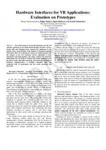
Fig. 2.
SNR-offset vs. SNR for OFDM and FBMC with different user velocities.
A similar equation has to be derived for the FBMC case. Note, that the transmit (and receive) filter isR given by the prototype T ˜ 2 j2πνt filter in (1). For the frequency-shift only case, the cross-ambiguity function reduces to Ahh (0, ν) = 0 |h(t)| e dt, with 1 ˜ = h(t). Moreover we have B = 1. h(t) γ kh(t)k2 As a first example, in this paper we investigate the influence of (Doppler) frequency shifts (induced by the user velocity) on OFDM and FBMC. We compare the same user velocities (3 and 120km/h) that we also consider in our system simulations. Figure 2 shows the results for different original SNR values for OFDM and FBMC. It can be observed that the influence of frequency offsets in FBMC is much lower. In particular the influence of the Doppler offsets at lower SNR and lower speed is close to 0.3dB for OFDM and rather small for FBMC, while in a high-velocity, high-SNR regime the original SNR is diminished up to 1.2 dB for OFDM and 0.8 dB for FBMC. C. SNR-PER Curves The actual link-to-system interface is a mapping from an effective SINR (or SNIDR in case of FBMC) to a corresponding packet error rate. This mapping has to be evaluated and fitted against measured packet error rates coming from link-level simulations in an equivalent AWGN channel.
Fig. 3.
BLER vs SNR in AWGN channel.
Figure 3 depicts the resulting curves generated with the particular elements discussed above. Thereby a convolutional encoder and viterbi decoder was used. Already here, the gain in FBMC from abandoning the cyclic prefix can be clearly observed. Based on the generated results depicted in Figure 3, lookup tables can be generated for usage in system level simulations. IV. S YSTEM S IMULATIONS A. FBMC Frame Structure In order to carry out system-level simulations and for performance comparisons between different waveforms we need suitable frame structures in the simulation. The frame structure has to be matched in order to enable a fair comparison (here to have the same throughput) between the waveforms, that is, they have to support the same throughput. The frames we use for FBMC is illustrated in Figure 4.
Fig. 4.
FBMC frame structure.
In the OFDM case we use 4 symbols for signaling/control etc. and 9 symbols for data with a total subframe duration of 0.93ms, while in FBMC we use 16 symbols for data with a total subframe duration of 1.63ms. A summary of the relevant modeling parameters is given in Table II. B. Configuration and Results We carry out system simulations in the downlink using the IS-Wireless LTE MAC Lab software and compare OFDM with FBMC. LTE MAC Lab belongs to a class of system-level simulators that reflects the behavior of a modeled radio access network, including the implementation of propagation and mobility models. The main focus of LTE MAC Lab is the area of RRM features (scheduling and link adaptation). In its architectural approach, a fine implementation granularity allows to easily incorporate the new FBMC waveform. In addition to the parameters summarized in Table II we use the following configuration. Two different user velocities are considered, 3km/h and 120km/h and a total number of 50 users is considered. Moreover we use a Max-SINR scheduler. The overall simulation time is 3.26s which amounts to 2000 FBMC TTIs and 3260 OFDM TTIs due to the frame structure and TTI definition as explained earlier. Additionally we average the results over six simulation runs. In this paper ideal feedback is used, thus channel state information is instantaneously available at the base stations. We perform simulations with two
TABLE II F RAMING PARAMETERS Parameter Useful bandwidth System band Number of carriers Number of active carriers Cyclic prefix Carrier spacing Sampling rate Sampling period Preamble symbols in subframe Data symbols in subframe Subframe duration Overlapping factor Number of resource blocks
FBMC 107 2 · 109 1024 601 N/A 15 · 103 15.36 · 106 65.1 · 10−9 4 16 1.63 · 10−3 4 50
OFDM 107 2 · 109 1024 601 72 15 · 103 15.36 · 106 65.1 · 10−9 4 9 0.93 · 10−3 N/A 50
Unit Hz Hz carriers samples Hz Hz s
s
different channel models, a 3GPP EVA channel with a coherence bandwidth of 398.41 kHz, and a 3GPP ETU channel which was modified to have a coherence bandwidth of only 108.06 kHz, in order to investigate the influence of high frequency selectivity. This is necessary since the additional distortion term in FBMC has only influence when the coherence bandwidth is smaller than the filter response in the frequency domain.
(a) Coherence bandwidth 108.06kHz.
(b) Coherence bandwidth 398.41kHz. Fig. 5.
SNIR-CDF comparison of OFDM vs. FBMC.
Figure 5 shows CDFs of SNI(D)R values obtained with the two waveforms for the two channels in consideration. For a large coherence bandwidth we can observe small gains from FBMC, especially at higher velocity, which stem from the smaller susceptibility to frequency offsets, as described above. In case of high frequency selectivity these gains vanish due to the additional distortion term in FBMC which now becomes active.
(a) Coherence bandwidth 108.06kHz.
(b) Coherence bandwidth 398.41kHz. Fig. 6.
User throughput CDF comparison of OFDM vs. FBMC.
(a) Coh. Bandwidth 108.06kHz. Fig. 7.
(b) Coh. Bandwidth 398.41kHz.
Average throughput comparison of OFDM vs. FBMC.
Figure 6 shows user throughput CDFs for the two channels. Gains from FBMC can be observed in both the “frequency-flat” and in the “frequency selective” case. These gains are primarily caused by the removal of the cyclic prefix. In the case with higher frequency selectivity the relative gains are slightly smaller due to the additional distortion. This can be better observed in Figure 7 where, for the ease of comparison, the average user throughputs for both waveforms and velocities are also depicted. V. C ONCLUSION This paper makes a first step towards system level simulations of non-orthogonal waveforms. For the FBMC example, we present a possible link-to-system interface comprising suitable quality measures, corresponding effective SNR mappings, and methods to incorporate frequency offsets. Moreover we propose a suitable frame structure for FBMC in the simulations. Comparing the influence of frequency shifts induced by user velocities, it turns out that FBMC is less sensitive to such frequency offsets, although their overall impact is not strong enough to significantly change the performance. We expect a much more relevant impact of timing offsets, however, this remains to be investigated. From first system simulations using the described link-to-system interface, it can be concluded that FBMC is (as expected) more efficient with small frequency selectivity, since in this case the gains of removing the cyclic prefix take the full effect. With larger frequency selectivity the gains that can be expected from using FBMC become slightly smaller. R EFERENCES [1] G. Wunder, P. Jung, M. Kasparick, T. Wild, F. Schaich, Y. Chen, S. ten Brink, I. Gaspar, N. Michailow, A. Festag, L. Mendes, G. Fettweis, N. Cassiau, D. Ktenas, M. Dryjanski, S. Pietrzyk, B. Eged, P. Vago, and Frank Wiedmann, “5GNOW: Non-Orthogonal, Asynchronous Waveforms for Future Mobile Applications,” IEEE Communications Magazine, 2014. [2] M. Bellanger et.al., “FBMC physical layer: a primer,” PHYDYAS, January, 2010. [3] K. Brueninghaus, D. Astely, T. Salzer, S. Visuri, A. Alexiou, S. Karger, and G.-A. Seraji, “Link performance models for system level simulations of broadband radio access systems,” in IEEE 16th International Symposium on Personal, Indoor and Mobile Radio Communications (PIMRC), vol. 4, 2005, pp. 2306–2311 Vol. 4. [4] A. Oborina, C. Ibars, L. Giupponi, and F. Bader, “Link Performance Model for System Level Simulations of Filter Bank Multicarrier-Based Systems in PMR Networks,” in Proceedings of the Tenth International Symposium on Wireless Communication Systems (ISWCS), 2013, pp. 1–5. [5] X. Mestre, M. Majoral, and S. Pfletschinger, “An Asymptotic Approach to Parallel Equalization of Filter Bank Based Multicarrier Signals,” IEEE Transactions on Signal Processing, vol. 61, no. 14, pp. 3592–3606, 2013. [6] D. Petrov, P. Gonchukov, and T. H. Stitz, “Link to System Mapping for FBMC Based Systems in SISO case,” in Proceedings of the Tenth International Symposium on Wireless Communication Systems (ISWCS), 2013, pp. 1–5. [7] R. Schoenen, C. Teijeiro, and D. Bultmann, “System Level Performance Evaluation of LTE with MIMO and Relays in Reuse-1 IMT-Advanced Scenarios,” in 6th International Conference on Wireless Communications Networking and Mobile Computing (WiCOM), 2010, pp. 1–5. [8] P. Jung and G. Wunder, “On Time-Variant Distortions in Multicarrier Transmission with Application to Frequency Offsets and Phase Noise,” IEEE Trans. on Communications, vol. 53, no. 9, pp. 1561–1570, Sep. 2005.