Journal of Physical Sciences, Vol. 10, 2006, 143 – 150
System Level Simulation of Servo Accelerometer in Simulink D. Prasanna Kumar1 and Kirat Pal2 Department Of Earthquake Engineering, I.I.T.Roorkee, Roorkee-247667, India E-mail: 1
[email protected],
[email protected] Received 31 December, 2006 ; accepted 31 December, 2006 ABSTRACT This paper describes the derivation of a detailed model of a forced balance (servo) accelerometer and its implementation in a commercial MATLAB package. The sensing element is modeled at a system level, the control and interface electronics at a component level. The MATLAB simulation tool, SIMULINK allows very realistic insight into the system behavior. A shaketable model is made with the help of SIMMECHANICS tool. The accelerometer model is mounted on the shaketable and the system is connected to VIRTUAL REALITY tool to show the actual working of the system dynamically at the run time. The amplitude results with respect to frequency ratio have been plotted for various input forms and their implications have been studied. 1. Introduction Force-balance transducers (FBT) differ from other types of transducers in that they have an electrical feedback loop. An equilibrium state of the transducer mass is obtained by balancing the input force (caused by absolute base acceleration) with an opposing exerted on the mass proportional to the output voltage or current of a force generator [1]. To approach equilibrium, an electrical pick-up is used to sense the relative mass movement, and its output is converted into the required feedback current or voltage to drive a force generator by way of an amplifier. The relative displacement sensor can be supplemented by a relative velocity sensing device. This can be affected through an electro-dynamic generator type transducer in the feedback loop or by phase-shifting networks in the main loop. Force-balance transducers can offer a wider useful response range than the open-loop conventional transducers. Damping can be achieved through a phase-shifting network or by a velocity-sensing pick up in the feed back loop. It should be noted that mechanical stiffness and damping are often negligible compared with electrically produced equivalent terms, and can often be ignored in the equilibrium analysis of the transducer vibrating mass. As pointed out by Neubert [2], instability due to environmental factors in the 143
144
D. Prasanna Kumar et al.
displacement and velocity sensors and in the amplifiers does not affect the accuracy of the force-balance transducers. However instability in the force generator does, since the feedback current or voltage is taken as a measure of input force. Thus, the problem of transducer stability has been shifted from sensing element and amplifier to the force generator. This device, called an accelerometer, has an overall size of a few hundred microns to a few millimeters, and is fabricated using micromachining technology. Micromachining is based on techniques that are originally developed to fabricate integrated circuits. Micromachined accelerometers are typically monolithic and do not require manual assembly. Thus, these devices are reliable, robust and inexpensive, and have received wide applications. In this paper we have reported the derivation of a detailed model of a forced balance accelerometer and its implementation in a commercial MATLAB package. The sensing element is modeled at a system level, the control and interface electronics at a component level. The modeling and simulation of accelerometer has also been done earlier using digital accelerometer.[3,4] 2. Principle of Acceleration Sensing As shown in Figure 1, the simplest model of an accelerometer[5] is a mass-spring-damper system that is attached to an enclosing casing. The applied acceleration of the casing causes the mass to move, and this motion can be used to determine the magnitude of the acceleration. x m a k
β
Figure 1. Accelerometer sensing principle. Let x be the displacement of the mass m relative to the casing. When the casing has acceleration a, the equation of motion for the mass is && + β x& + kx = − ma, mx Where β and k are the damping coefficient and spring constant, respectively. Thus, the acceleration can be determined by measuring x, i.e., the net stretch or compression of the spring. The behavior of this dynamic system is determined by two parameters: the natural frequency ωn = k / m , and damping ratio ζ = β / 4mk . Using these parameters, the equation of
System Level Simulation of Servo Accelerometer in Simulink
145
motion becomes
x&& + 2ζωn x& + ω2n x = −a. The solution to this equation consists of a transient response which depends on the specific initial conditions, and a steady-state response, which is independent of initial conditions. If the response of the system is sufficiently fast, it is reasonable to ignore the transient response[6]. Focusing on the steady state response, we introduce two important performance parameters as follows: 1.
Minimum detectable acceleration. Let the applied acceleration be a constant. The steady state response is then x = a / ω2n . In other words, the steady-state net stretch or compression of the spring is directly proportional to the applied acceleration. Suppose that the minimum measurable spring deflection is xmin, then the minimum detectable acceleration of the accelerometer is given by
a min = xminω2n . 2.
Bandwidth. Let the applied acceleration be a sinusoid with circular frequency ω, i.e.,
a = a 0 cos(ωt ). The steady-state deflection of the spring is of the form x = x 0 cos(ωt + φ). The deflection magnitude x0 is related to the magnitude of the applied acceleration a0 by x 0 (ω) =
a0 1 ⋅ 2 2 ωn [( ω / ωn ) − 1]2 + 4 ζ2 ( ω / ωn )2
As indicated by the notation, x0 depends on the driving frequency,ω. In particular, x0 becomes diminishingly small when ω is sufficiently large, and the accelerometer will cease to be useful for accelerations at such a frequency. In practice, the bandwidth within which the accelerometer is useful is given by the cutoff frequency ωc. This frequency is defined by the equation x 0 (ωc ) / x 0 (0 ) = 1 / 2 , and is given by
ωc = γωn Where γ = 1 − 2ζ 2 + (1 − 2ζ 2 )2 + 1
146
D. Prasanna Kumar et al.
3. Forced Balance Accelerometer
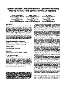
Figure 2. A simple forced balance accelerometer As said earlier, these accelerometers differ from the other types in that they have an electrical feed back loop A current proportional to the displacement transducer output, will force the mass to remain stationary relative to the frame.
Figure 3. Response amplitude as a function of frequency ratio Characteristics : 1. The FBA principle is now the heart of nearly all modern strong motion and broad sensors recording in a large frequency band like 0.01 to 50Hz. 2. In the measurement of low frequency low intensity acceleration the best accuracy characteristics are provided. 3. The total range of this deflection is extremely small. 4. Provides microgravity resolution with high zero-hertz stability and low thermal errors. 5. Not suited to high shock environments. 6. Better linearity. 7. Damping is achieved through electronic circuits. 8. Damping and natural frequencies can be adjusted by altering the electrical components in feedback loop.
System Level Simulation of Servo Accelerometer in Simulink
147
4. Mathematical Model The development of a mathematical model of accelerometer is a very important consideration in the design of any transducer
Figure 4. Mathematical model of sensing element for an accelerometer Here, the damping cannot be assumed to be linear because the gap between the electrodes and the proof mass is much smaller than the area of the plates. As the mass moves towards an electrode the air cannot escape fast enough, pressure is built up resulting in a dependency of the damping coefficient of the position of the proof mass. The saturation block represents the physical restraint in movement of the seismic mass due to the top and bottom electrodes. The input to the system is the acceleration force acting on the proof mass causing to deflect it from the rest position; the output signal is a measure of the position of that mass. For simplicity it is assumed that the feedback voltage is applied to one electrode for an entire cycle, in reality, one cycle is divided into sensing and feedback periods. 5. Simulation and Results [5,6] Figure-5 below represents the SIMULINK block diagram used for simulation. Here, the shake table is modeled with SIMMECHANICS library. The accelerometer mounted on the shaketable is also shown. The VR sink block represents the virtual reality experience which will show the actual working of the accelerometer mounted on shake table. The simulation results have been plotted with amplitude ratio on y-axis and frequency ratio on xaxis for step input and sinusoidal input below(figs.6-7). The plots have been categorized as under damped, critical damped and over damped. In both the cases, as the damping increases the mass fluctuation amplitude will decrease and comes to rest in less time.
148
D. Prasanna Kumar et al.
Figure. 5. SIMULINK block diagram in MATLAB
Figure. 6 Results for step input
System Level Simulation of Servo Accelerometer in Simulink
149
Figure. 7 Results for sinusoidal input 6.
Conclusions 1. The model of accelerometer derived in this work proved to be a valuable tool to predict and evaluate the system performance before implementing the sensor in hardware. 2. MATLAB is suitable to implement models of non-electrical components which are described at a behavioral level, consequently, the entire microsensor system can be simulated omprising the sensing element and the interface electronics. 3. The simulation can help to develop alternative interface electronics and control strategies. The approach relies on readily available simulation tools and is relatively easily applicable to other micromachined sensors (e.g. gyroscopes ) provided that a lumped parameter mathematical model for the micromachined part is available 4. In order to maintain high sensitivity, the proof mass has a low resonant frequency and a high quality factor. a simple but effective means to synthesize a control system is successively exerted so that the system has broadened the bandwidth and optimized damping while maintaining its high sensitivity. 5. The results obtained by the different approaches are sufficiently in agreement for confidence in the results to be justified. Although the results have not been compared with actual measurements, the testing on the sensing element at an earlier stage, resulted in a satisfactory outcome.
D. Prasanna Kumar et al.
150
1. 2. 3.
4. 5. 6.
REFERENCES Ali Amini and Mihailo Trifunac, Analysis of a force balance Accelerometer, Soil Dynamics and Earthquake Engineering, Vol.4, No-2, pp 82-90, 1985. Neubert, Herman K., Instrument Transducers: An Introduction to their Performance and Design, Oxford, Clarendon, Press, 1975(2nd Ed.). Simulation of a Micromachined Digital Accelerometer in SIMULINK and PSPICE Christopher P. Lewis, Michael Kraft Coventry University, School of Engineering, Priory St., Coventry, CV1 5FB, UK. MATLAB website, MATLABDocumentation, , Febrauary,2005 Clough, Ray W., and Penzien , Joseph, Dynamics of Structures, McGraw Hill, Inc., 1975. George Juraj Stein, Some recent developments in accelerometer sensors, Measurment Science review, Vol.1, pp 46-56.,2001