3.1.2 System Components of Smart Cameras . . . . . . . . . . 30. 3.1.3 Embedded
Technology for Building Smart Cameras . . . 30. 3.2 Taxonomy of Smart Cameras
.
Systematic Design of Self-Adaptive Embedded Systems with Applications in Image Processing ¨ der Der Technischen Fakultat ¨ Erlangen-Nurnberg Universitat ¨ zur Erlangung des Grades DOKTOR-INGENIEUR vorgelegt von Stefan Wildermann
Erlangen – 2012
Als Dissertation genehmigt von der Technischen Fakult¨at der Universit¨at Erlangen-N¨ urnberg Tag der Einreichung: . . . . . . . . . . . . . . . . . . . . . . . . 16. April 2012 Tag der Promotion: . . . . . . . . . . . . . . . . . . . . . . . . . . .25. July 2012 Dekanin: . . . . . . . . . . . . . Professorin Dr.-Ing. Marion Merklein Berichterstatter: . . . . . . . . . . . Professor Dr.-Ing. J¨ urgen Teich Professor Dr.-Ing. Christian M¨ uller-Schloer
Acknowledgments I would like to express my sincere gratitude to Prof. J¨ urgen Teich for his supervision and fruitful discussions throughout this work. His ideas, his enthusiasm, and his constant support were always encouraging factors during my work. I also wish to thank Prof. Christian M¨ uller-Schloer for being the co-examiner of this work. My thanks also go to the other members of the Ph. D. commitee, Prof. Rolf Wanka and Prof. Sebastian Sattler. I have had a great deal of assistance and support from as well as discussion with my colleagues and students at the Chair of Hardware/Software Co-Design. Particularly, I have to thank Andreas Weichslgartner, Andreas Oetken, and Felix Reimann who supported me a lot during this work. I also wish to thank Prof. Zoran Salcic for the fruitful discussions during his stay in Erlangen. I am particularly grateful to all my friends and my family for their encouragement and motivation from outside the academia. My biggest thanks go to my parents and to my wife Alina for all their love and support – without you I could never have done this.
Stefan Wildermann Erlangen, December 2012
iii
Contents
1
Introduction
1.1 1.2 1.3 1.4 1.5 2
. . . . .
. . . . .
. . . . .
. . . . .
. . . . .
. . . . .
. . . . .
. . . . .
. . . . .
. . . . .
. . . . .
. . . . .
. . . . .
. . . . .
. . . . .
. . . . .
. . . . .
Self-adaptive Systems
2.1 2.2
2.3 2.4 2.5 2.6
2.7 3
Self-adaptive Systems . . . . . . . Embedded Computer Vision . . . Self-adaptive Embedded Systems Contributions of this Thesis . . . Outline of this Thesis . . . . . . .
1
Hierarchical Classification of Self-* Properties Adaptive and Self-managing Systems . . . . . 2.2.1 Definition of Adaptive Systems . . . . 2.2.2 Definition of Self-managing Systems . . Behavior Adaptation . . . . . . . . . . . . . . Self-adaptive and Self-organizing Systems . . . Self-Adaptation in Embedded Systems . . . . Related Work . . . . . . . . . . . . . . . . . . 2.6.1 Organic Computing . . . . . . . . . . . 2.6.2 Reconfigurable Computing . . . . . . . 2.6.3 Invasive Computing . . . . . . . . . . . Summary . . . . . . . . . . . . . . . . . . . .
11
. . . . . . . . . . . .
. . . . . . . . . . . .
. . . . . . . . . . . .
. . . . . . . . . . . .
. . . . . . . . . . . .
. . . . . . . . . . . .
. . . . . . . . . . . .
. . . . . . . . . . . .
. . . . . . . . . . . .
. . . . . . . . . . . .
Embedded Imaging in Smart Cameras
3.1
3.2 3.3 3.4
2 3 3 4 9
Smart Cameras . . . . . . . . . . . . . . . . . . . . . . . . 3.1.1 Characteristics of Smart Cameras . . . . . . . . . . 3.1.2 System Components of Smart Cameras . . . . . . . 3.1.3 Embedded Technology for Building Smart Cameras Taxonomy of Smart Cameras . . . . . . . . . . . . . . . . Related Work . . . . . . . . . . . . . . . . . . . . . . . . . Summary . . . . . . . . . . . . . . . . . . . . . . . . . . .
11 13 13 15 17 20 21 25 25 26 27 27 29
. . . . . . .
. . . . . . .
. . . . . . .
29 29 30 30 33 34 36
v
Contents 4
A Methodology for Self-adaptive Object Tracking
4.1 4.2 4.3 4.4
4.5
4.6 4.7 5
5.2
5.3
5.4
5.5
. . . . . . . . . . . . .
. . . . . . . . . . . . .
. . . . . . . . . . . . .
. . . . . . . . . . . . .
Static Hardware/Software Co-Design of Self-adaptive Multi-Filter Fusion . . . . . . . . . . . . . . . . . . . . . . . . . . . . . . . . 5.1.1 The Prototype Platform . . . . . . . . . . . . . . . . . . 5.1.2 Hardware/Software Partitioning . . . . . . . . . . . . . . 5.1.3 Experimental Results . . . . . . . . . . . . . . . . . . . . 5.1.4 Conclusion . . . . . . . . . . . . . . . . . . . . . . . . . . Partially Reconfigurable Systems . . . . . . . . . . . . . . . . . 5.2.1 Challenges of Partial Reconfiguration . . . . . . . . . . . 5.2.2 Enabling Partial Reconfiguration in Tiled FPGA Architectures . . . . . . . . . . . . . . . . . . . . . . . . . . . 5.2.3 Communication Techniques . . . . . . . . . . . . . . . . Partially Reconfigurable System-on-Chip Architectures . . . . . 5.3.1 Reconfigurable On-Chip Bus . . . . . . . . . . . . . . . . 5.3.2 Reconfigurable Modules . . . . . . . . . . . . . . . . . . 5.3.3 PLB/RCB Bridge . . . . . . . . . . . . . . . . . . . . . . 5.3.4 I/O Bar . . . . . . . . . . . . . . . . . . . . . . . . . . . Implementation and Experimental Results . . . . . . . . . . . . 5.4.1 Reconfigurable System on Chip (SoC) Design . . . . . . 5.4.2 Smart Camera Application . . . . . . . . . . . . . . . . . 5.4.3 Run-time Self-Reconfiguration . . . . . . . . . . . . . . . 5.4.4 Evaluation of the Tracking Application Implementation . Summary . . . . . . . . . . . . . . . . . . . . . . . . . . . . . .
Formal Description of Self-adaptive Reconfigurable Systems
38 38 41 42 43 45 46 46 49 49 52 59 61 65
A Design Methodology for Self-adaptive Reconfigurable Systems
6.1
vi
. . . . . . . . . . . . . . . . . . . . . . . . . . . . . . . . . . . . . . . . . . Integration . . . . . . . . . . . . . . . . . . . . . . . . . . . . . . . . . . . . . . . . . .
Architectures for Self-adaptive Embedded Systems
5.1
6
Related Work . . . . . . . . . . . . . . . . . Probabilistic Tracking . . . . . . . . . . . . Multi-filter Tracking with Particle Filters . . 4.3.1 Multi-Object Tracking . . . . . . . . Self-Adaptive Multi-filter Tracking . . . . . 4.4.1 System Monitoring . . . . . . . . . . 4.4.2 Parameter Adaptation by Democratic 4.4.3 Structure Adaptation . . . . . . . . . Experimental Evaluation . . . . . . . . . . . 4.5.1 System Setup . . . . . . . . . . . . . 4.5.2 Results . . . . . . . . . . . . . . . . . Discussion . . . . . . . . . . . . . . . . . . . Summary . . . . . . . . . . . . . . . . . . .
37
66 66 66 71 72 74 74 76 78 79 80 81 82 84 87 87 89 91 95 97 99
. .
99
Contents 6.2
6.3 6.4
6.5
6.6
6.7
6.8
6.9 7
Related Work . . . . . . . . . . . . . . . . . . . . . . . . . . . . 103 6.2.1 Design Flows for Reconfigurable Systems . . . . . . . . . 103 6.2.2 System Level Design Methodologies . . . . . . . . . . . . 106 System Level Synthesis Flow for Self-adaptive Multi-mode Systems111 Exploration Model . . . . . . . . . . . . . . . . . . . . . . . . . 113 6.4.1 Application Model . . . . . . . . . . . . . . . . . . . . . 114 6.4.2 Architectural Model . . . . . . . . . . . . . . . . . . . . 115 6.4.3 Design Space . . . . . . . . . . . . . . . . . . . . . . . . 118 6.4.4 Feasible Implementations . . . . . . . . . . . . . . . . . . 120 Configuration Space Exploration by Feasible Mode Exploration 120 6.5.1 Problem Formulation (Configuration Space Exploration) 121 6.5.2 Analysis of Feasible Modes . . . . . . . . . . . . . . . . . 121 6.5.3 Feasible Mode Exploration Algorithm . . . . . . . . . . . 123 6.5.4 Pseudo Boolean SAT Solving . . . . . . . . . . . . . . . 125 6.5.5 Symbolic Encoding of Feasible Modes . . . . . . . . . . . 127 DSE of Partially Reconfigurable Multi-mode Systems . . . . . . 132 6.6.1 Problem Formulation (Design Space Exploration) . . . . 132 6.6.2 SAT Decoding for DSE . . . . . . . . . . . . . . . . . . . 133 6.6.3 Symbolic Encoding of Multi-mode Implementations . . . 134 Pruning Strategy . . . . . . . . . . . . . . . . . . . . . . . . . . 138 6.7.1 Partitioning and Placement as Problem Hierarchies . . . 138 6.7.2 Motivational Example . . . . . . . . . . . . . . . . . . . 140 6.7.3 Combining Partitioning and Placement (comb) . . . . . . 143 Experimental Evaluation . . . . . . . . . . . . . . . . . . . . . . 144 6.8.1 Feasible Mode Exploration . . . . . . . . . . . . . . . . . 145 6.8.2 Comparison of Design Space Exploration with a State-ofthe-Art Approach . . . . . . . . . . . . . . . . . . . . . . 159 6.8.3 Evaluation of Pruning Strategy for Design Space Exploration . . . . . . . . . . . . . . . . . . . . . . . . . . . . 164 6.8.4 Conclusion . . . . . . . . . . . . . . . . . . . . . . . . . . 168 Summary . . . . . . . . . . . . . . . . . . . . . . . . . . . . . . 170
Conclusion and Future Directions
7.1
173
Future Directions . . . . . . . . . . . . . . . . . . . . . . . . . . 175
German Part
177
Bibliography
183
Author’s Own Publications
203
List of Symbols
207
vii
Contents Acronyms
211
Index
213
viii
1
Introduction
In 1965, Gordon Moore stated his famous law [Moo65], saying that the number of transistors that can be placed inexpensively in an integrated circuit (IC) doubles approximately every two years. Despite its empirical foundation, the prediction has proven right since its formulation. This trend has affected our life today more drastically than one might have expected back then. The last decades witnessed the development of the personal computer and the Internet. Nowadays, ICs have become an integral part of a multitude of devices and equipment with which we are dealing everyday, and we are speaking of embedded systems as they are computer systems that are embedded into a technical context. Their fields of application cover many areas. From telecommunication systems, automobiles, to consumer electronics – embedded systems can be found nearly everywhere. This ubiquity of computers in our everyday life has led to the paradigm of ubiquitous computing. It was introduced by Mark Weiser, who already argued in 1991 [Wei91] that specialized elements of hardware and software will be so ubiquitous that no one will notice their presence. While we think of the prospects of how Moore’s law affects the computational power of modern embedded technology, we must not forget that the complexity of embedded system design grows equally. Designing embedded systems of any kind already is a tedious task. Many approaches have been proposed and applied for several years. But, as we will also see in this thesis, the complexity of novel embedded applications makes it even more difficult to design such systems. Embedded systems operating in dynamic and highly unpredictable real world environments have to provide multiple, often very computationally expensive algorithms on the one hand. On the other hand, they are subject to stringent design constraints, e.g., regarding their cost, size, real-time capabilities and power consumption, which drastically reduces the available processing power. Self-adaptation is a promising concept to tackle this problem. Self-adaptive systems are able to autonomously change their behavior at run-time to react to changes of the environment, of the system objectives, or of the system itself. The remainder of this chapter gives an introduction to self-adaptive systems. Embedded imaging is then motivated as the field of application for embedded technology that is considered in this thesis. After having motivated both topics,
1
1.
Introduction
combining concepts of self-adaptivity with embedded system design are briefly discussed, listing the expected benefits, but also the challenges that arise. The chapter is concluded by providing all steps necessary to tackle these challenges and establish this symbiosis. These steps form the contributions of this thesis and are explained in detail in the remainder of this work.
1.1 Self-adaptive Systems Computers were and are employed to assist humans by performing tasks that require an interaction with the physical world. With the increasing complexity of embedded system architectures and applications as well as their ubiquity, it is impossible that all possible environmental contexts and scenarios can be foreseen and covered at design time. Likewise, it is impossible that human operators are able to observe and control the behavior of the system around-theclock during its operation. As a result, a significant portion of the total cost of ownership of modern computing system is due to their operation, maintenance, and administration. The following statement was made by Aseltine et al. in the year 1958, but is still valid today: Adaptation – the ability of self-adjustment or self-modification in accordance with changing conditions of environment or structure – is a fundamental attribute of living organisms. It is certainly a desirable attribute for a machine. [AMS58] Computer systems consist of parameters, components with relationships (structure) and other internal and external attributes that are generally referred to as the configuration of the system and determine its behavior. By changing the configuration, also the behavior is changed as a consequence. This is exploited for realizing the run-time behavior adaptation of systems, where techniques are classified accordingly into parameter adaptation and structure adaptation [ADG+ 09]. The set of all configurations of a system which can be generated by such techniques is called the configuration space of the system. Now, selfawareness is a concept stipulating that the system itself is aware of its own behavior, parameters, structure, objectives, and goals. According to [ST09], a system can then be denoted to be self-adaptive if it monitors and evaluates these entities and then autonomously performs behavior adaptation when unable to accomplish the intended goals, or when a better performance is thus achievable. As a result, self-adaptive systems exhibit abilities that are generally denoted as self-* properties [KC03]. Many works and research projects deal with building this kind of systems. Popular examples are IBM’s Autonomic Computing paradigm [Hor01] and the Organic Computing initiative [Sch05]. The terminology is often ambiguously
2
1.2 Embedded Computer Vision used. Therefore, Section 2 introduces a common notion that is used throughout this thesis.
1.2 Embedded Computer Vision The progress in computer technology allows embedded computers to be integrated into cameras. This results in embedded vision systems, where hardware and software can work together to perform complex image processing tasks. The idea is that, besides generating video streams, the camera system is able to extract application-specific information from the sensor data. Several fields of application deploy embedded vision systems [RB10]. Examples are surveillance and monitoring. Moreover, embedded vision system become part of vehicles to an increasing extent with the purpose to enhance safety by providing sophisticated driver assistance systems. Furthermore, robotics and human-machine-interfaces require to perform complex vision tasks so that a person is able to interact with the machine by means of gestures. Section 3 gives an introduction to the topic of embedded computer vision. In this context, smart cameras play an important role. In all the above use-cases, the camera system is operating in highly dynamic, unpredictable, and often unknown environments. This does considerably differ from the classical deployment of embedded systems, like reactive systems and closed-loop controllers, which perform control tasks within technical contexts that have degrees of freedom which are more or less well-defined or can at least be delimited. For example, the behavior of a plant regulated by a closed-loop controller and all required parameters can be analyzed a priori and simulated. This is not the case for embedded camera systems. Due to the uncertainty and diversity of the environment, it might be necessary that the system adapts the image processing routine during operation to the requirements of the current context and situation. Consequently, it is desirable that it exhibits a self-adaptive behavior.
1.3 Self-adaptive Embedded Systems Building self-adaptive embedded systems in general might have different motivations. One is to increase the reliability and make the system more faultresistant. For example, hardware faults can be compensated by adapting the system configuration [HKR+ 10]. A second motivation is to provide systems which functionalities can be modified by an external user, and then have the ability to incorporate the new functions autonomously into the system configuration [SHE06]. The third is to enhance the system with the ability to
3
1.
Introduction
regulate itself for meeting and maintaining Quality of Service (QoS) measures [STH+ 10]. The fourth is to realize systems that offer context-aware functionality [CS10, DEG11]. This thesis deals with self-adaptive systems of the fourth kind, where a camera system serves as case study that applies different image processing algorithms depending on the environmental context. Software systems employ general-purpose processors for their implementation which can be flexibly used and are designed to support a wide range of applications. In contrast, embedded systems are specialized computer systems dedicated to a specific application. An embedded system gets fixed during a process called hardware/software co-design [Tei12]: The hardware architecture is generated by selecting the computing resources (allocation), the functionality is assigned to the resources (binding), communication is routed, and a schedule is determined to resolve resource contention. Technically, parameter adaptation is possible in such a system, e.g., by changing the values of variables. However, structure adaptation cannot be achieved in such a static design. As a first solution to this problem, online techniques for hardware/software co-design have been proposed to adapt the system during operation without any a priori knowledge and information, like [SLV03, HKR+ 10, ZBS+ 11]. In cases where also the hardware structure of the system gets adapted at run-time, reconfigurable computing techniques [Bob07, PTW10] are applied, as they unify the performance of hardware with the flexibility of software. However, the problem is that embedded systems may have very stringent constraints on the one hand, but systems that employ such online techniques have a non-deterministic behavior and cannot be verified on the other hand. The second approach is therefore to provide a design methodology that considers the ability of self-adaptation throughout the design process. So, the final result is an embedded system which can adapt itself within a pre-defined configuration space which was verified beforehand. There are already some basic principles for realizing such design methodologies. They either provide techniques to verify the self-organizing mechanisms during the design phase which can then be safely applied to control the underlying system at run-time, e.g., [SHE06, NSS+ 11, SNSR11], or incorporate the verification into the design process of the overall system, e.g., [GLHT09, DEG11]. Nonetheless, the thesis at hand provides a holistic approach for embedded system design for the first time.
1.4 Contributions of this Thesis Embedded systems of any kind should have low cost, be small and power efficient. This implies limited capacity for providing functionality on the one hand. On the other hand, many embedded systems, particularly embedded cameras, are operating in unknown, dynamic, and often unpredictable real world envi-
4
1.4 Contributions of this Thesis ronments so that a variety of complex algorithms is required for a robust operation of the system. Consequently, context-aware and resource-aware adaptation by re-organizing the running algorithms can lead to a better utilization of the system resources while retaining and possibly even optimizing the processing quality of the system. This means that several algorithms are provided during the design phase, where not all of them can run concurrently due to system constraints. The system, however, has the ability to select the configuration that is most suitable for the current context at run-time. As a result, the available resources can be optimally utilized. In particular, it is a promising approach to combine self-adaptive systems and embedded imaging. To achieve this goal, the following aspects have to be considered: A) Provide methods and algorithms on the application level, tailored for adaptive image processing in embedded systems. B) Exploit and design reconfigurable hardware architecture concepts to support embedded systems that can dynamically adapt their behavior and structure at run-time. C) Make tools and methodologies available that enable the design, verification, and optimization of self-adaptive embedded systems. In the following, the main contributions of this thesis in the above three areas are outlined. Throughout this thesis, embedded image processing will serve as the driving case-study. Many results (particularly from aspects B) and C)) are however applicable for any embedded system which exhibits the above characteristics. A) Methodology for self-adaptive object tracking applications: Computer vision is one of the key research topics of modern computer science and finds application in manufacturing, surveillance, automotive, robotics, and sophisticated human-machine-interfaces. In all those use cases, object tracking is a key component of higher-level applications that require the location and/or shape of objects in every frame. A challenge is that tracking is performed on data that is captured from a highly unpredictable and uncertain environment. A common approach to provide robustness in such a context is to apply and fuse multiple image processing applications which rely on several features of the object like color, motion, and shape. This means that a variety of different and complex image processing algorithms is required on the one hand. On the other hand, an embedded camera system performing object tracking has to be small, power-efficient, real-time capable, and have low cost for being feasibly and economically deployable in the above contexts.
5
1.
Introduction
As a remedy, this thesis provides a generic methodology for object tracking. It is based on the concept of multi-filter fusion, which means that a variety of filters are concurrently calculated on the same input image and then fused by a tracking component [WWZT09*]1 . Particle filtering is applied as a probabilistic approach for fusing the filter results [WT08a*]. The advantage of probabilistic tracking is that the environment and objects are internally represented through probability distributions, so that the uncertainty is an integral part of the tracking algorithm itself. The proposed methodology additionally provides a self-adaptation mechanism [WOTS10*] on top of that image processing part. Therefore, quality measures are provided, which are calculated by a monitoring component and quantify how good and efficient the tracking system works. Based on their evaluation, different adaptation strategies are applied, where one is parameter adaptation and the other is structure adaptation. The methodology provides a generic template that can be instantiated when building self-adaptive embedded smart camera systems. As already motivated, several resource constraints, computational constraints, and other non-functional constraints exist when designing and deploying smart cameras due to feasibility and economical considerations. Consequently, not necessarily all available image processing applications may be able to run concurrently. Therefore, the presented methodology includes a structure adaptation strategy that changes the system components at run-time: It is possible to switch between configurations running different subsets of filters. As a consequence, still a variety of different features can be used to track an object despite the system constraints. In this realm, this thesis provides an adaptation algorithm for deciding when and which features are most suitable. B) Reconfigurable architecture concept: Of course, it is possible to apply standard design tools and technologies to build self-adaptive embedded camera systems. Here, the thesis presents a static hardware/software co-design of a multi-filter fusion tracker as a case-study [WWZT09*]. It shows that the throughput can be significantly increased compared to a software-only implementation running in parallel on a general-purpose multi-core processor. Moreover, the system is able to process the images at low system clock rates, which considerably reduces the power consumption of the system. The co-design furthermore provides a feedback loop for performing parameter adaptation, where the contribution of the image processing filters to the tracking result can be regulated. However, neither standard design flows nor standard technologies do support structure adaptation where the configuration of the embedded system is adapted and where, in particular, the hardware is modified at run-time. As a 1
6
The author’s own publications are marked with a * and are summarized on pp. 203-205
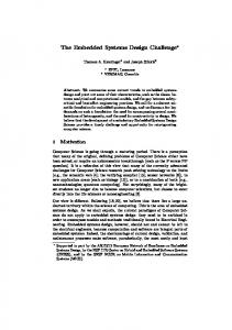
1.4 Contributions of this Thesis remedy, this thesis furthermore presents a partially reconfigurable SoC architecture concept for implementing self-adaptive systems. The presented architecture concept [OWTK10*] has several novel contributions: First, it is possible to build architectures for loading and placing hardware modules on a very fine granularity. Second, communication concepts are provided that enable system-wide communication and assembling of data processing pipelines even when modules are dynamically reconfigured at run-time. Third, a concept for fast memory transfers of hardware modules is provided. Finally, the architecture includes a concept for self-reconfiguration, so that adaptation mechanisms are able to modify the system configuration at run-time. This architecture can be applied to build structure-adaptive autonomous camera systems based on the provided self-adaptive object tracking methodology. C) Design methodology for self-adaptive reconfigurable systems: Finally, this thesis proposes a novel design methodology for building self-adaptive embedded systems that provide context-dependent functionality. It targets systems that execute different sets of applications depending on the current context. This is is also the case in the self-adaptive object tracking methodology, which suggests to execute different subsets of image processing filters. From a technical point-of-view, the adaptation affects the structural implementation of the system. As context-dependent configurations are executed mutually exclusive, resource sharing between their implementations is possible for achieving a better resource utilization. This can be further enhanced by exploiting hardware reconfiguration. An abstract view of this class of systems is illustrated in Figure 1.1. A configuration of the system is given as the set of applications that are currently executed on the reconfigurable system architecture. The application base contains the set of all available applications which may be started by a control mechanism via an appropriate interface in reaction to environmental changes or other changes of the context. For embedded systems, stringent constraints exist for the execution of applications on the provided hardware architecture, what does not only include the functional correctness, but also non-functional requirements regarding real-time properties, throughput, and so on. A feasible system configuration is therefore a subset of applications that does not violate these constraints. A methodology for this domain requires two mandatory design steps: First, configuration space exploration is necessary to determine all feasible configurations that do not violate system constraints. Second, design space exploration is required that determines an optimized system level implementation for each configuration. To realize such a design methodology, this thesis makes the following contributions. First, a formal Model of Computation (MoC) is provided for expressing the application range and the configuration space. Second, a
7
1.
Introduction
reconfigurable architecture
add interface
configuration constraints
control mechanism
e remov load
application base
Figure 1.1: Use case of a self-adaptive reconfigurable system for context-aware
and resource-aware execution of multiple applications. A control mechanism dynamically changes the configuration at run-time by reconfiguring the software, but also field-programmable hardware.
formal Model of Architecture (MoA) is introduced that is able to capture the characteristics of run-time reconfigurable architectures, also including the concept of hardware reconfiguration. This means that it is able to capture spatial aspects of 2-dimensional placement of hardware modules, and it proposes modeling alternatives for the most common communication techniques applied in building run-time reconfigurable systems. Third, a formal technique for configuration space exploration is presented [WRTS11*]. It has the purpose to statically determine the possible configurations between which the control mechanism can then switch at run-time. It thus verifies the correct functionality of the system, despite of dynamically switching between these configurations. Furthermore, the exploration and optimization of system configurations at design time enables the implementation of optimized and efficient self-adaptive systems, as it would be too costly or infeasible to optimize each configuration at run-time. As fourth contribution, the methodology therefore provides design space exploration for static optimization at design time of the self-adaptive system [WRZT11*]. The technique considers the reconfiguration overhead arising at run-time as an additional problem dimension, so that resources are better utilized mutually exclusive by different configurations. Furthermore, it takes into account the transition time of switching between configurations. Configuration space exploration and design space exploration for self-adaptive reconfigurable systems are decision problems that are known to be NP-complete. A further contribution of this thesis is therefore to provide strategies that introduce different problem hierarchies of these decision problems [WTZ11*]. By solving the problem on each hierarchy in a top-down fashion, it is possible to prune parts of the typically huge search space of the problem. As a result, the execution
8
1.5 Outline of this Thesis times of configuration space exploration and design space exploration can be drastically reduced.
1.5 Outline of this Thesis This thesis has the following organization. Chapter 2 provides an introduction and formal definition of self-adaptive systems. The chapter summarizes definitions from literature to provide a precise foundation of the terminology used throughout this thesis. Furthermore, the challenges and state-of-the-art of designing self-adaptive embedded systems are listed. Chapter 3 gives an introduction to embedded imaging. The discussion focuses on self-adaptivity in smart cameras and presents the state-of-the-art. Chapter 4 presents the methodology for self-adaptive object tracking. It provides a generic template that can be instantiated when building self-adaptive embedded smart camera systems. Therefore, it includes mechanisms for performing parameter and structure adaptation. The influence of these techniques is evaluated by means of experiments. Furthermore, the extendability of the methodology is discussed. This chapter is based on the author’s own work described in [WT08a*], which presents the applied tracking algorithm, and [WOTS10*], which presents the self-adaptive tracking methodology adopted by this thesis. Chapter 5 details design options for implementing self-adaptive tracking in embedded systems based on two technologies. The first is a static hardware/ software co-design which can be realized with standard design flows and technology. The second is a partially reconfigurable architecture that enables to dynamically exchange hardware modules at run-time. Several concepts are provided to enable such structure-adaptive reconfigurable systems. It is evaluated by means of an object tracking application. This chapter summarizes the author’s own work described in [WWZT09*], which presents the static implementation of a self-adaptive embedded system, [AWST10*, WAST12*], which present online techniques for exploiting partial hardware reconfiguration for executing dynamic applications, and [OWTK10*], which presents the partially reconfigurable architecture concept. Chapter 6 describes a novel design methodology for self-adaptive reconfigurable embedded systems. The chapter introduces concepts for modeling such systems, for static exploration of all possible and feasible system configurations, and for optimization of the system implementation regarding multiple objectives like cost, power consumption, etc. In addition, strategies for pruning the search space are presented. The result of this flow is an embedded system which has the ability to switch between operational modes for adapting its behavior.
9
1.
Introduction
The methodology is applied for mapping the provided tracking application onto the provided reconfigurable hardware architecture. Several experiments are performed that give evidence of the efficiency of the methodology comparing it to the state-of-the-art. The contribution of this chapter is based on the author’s own work described in [WRTS11*], which presents an algorithm for statically exploring feasible system configurations, [WRZT11*], which presents the applied design space exploration technique, and [WTZ11*], which introduces the pruning strategy.
10
2
Self-adaptive Systems The purpose of this chapter is to establish a common notion of self-adaptivity. Inherent with the term of self-adaptivity are further concepts, which are commonly denoted as self-* properties. With these formal definitions, the focus is then put onto self-aware adaptation in embedded systems. This section also gives an overview of the state-of-the-art related to this topic.
2.1 Hierarchical Classification of Self-* Properties Several properties have been defined in the literature that characterize systems which are denoted as being self-adaptive or self-organizing. These properties are often summarized under the term “self-* properties”. Many interpretations and uses exist for these terms and concepts. In the following, a unified hierarchical classification is given based on [ST09], which defines this hierarchy in three levels as outlined in Figure 2.1. • General level. This level contains the general terms self-adaptation and self-organization. They are generally used to label autonomous systems2 which exhibit internal control mechanisms (see Section 2.2.2) to provide self-* properties as defined in the major level of this classification. The difference between both concepts is how the control mechanism is realized. Self-adaptive, also called weakly self-organizing, systems are characterized by a centralized control mechanism (see Section 2.4). Whereas, self-organizing systems have a decentralized control mechanism. The self-* properties are a result of the interaction of the distributed control mechanism. This formation of a global behavior based on local rules is denoted as emergence [MSS08]. • Major level. This level contains the four major properties of self-adaptive and self-organizing systems. These properties can actually be observed 2
The term autonomous will be used in the following independently of whether the system is self-adaptive or self-organizing.
11
2.
Self-adaptive Systems
general level
major level (self-managing)
primitive level
self-adaptation self-organization self-configuring self-optimizing self-awareness
self-healing self-protecting context-awareness
Figure 2.1: Hierarchy of self-* properties according to [ST09].
from the behavior of the system. They were first summarized by Kephart and Chess [KC03] and nowadays are the de-facto standard attributes assigned to self-* systems. They summarize these properties under the term of self-management. All concepts are defined in analogy to biological mechanisms. 1. Self-configuring means that systems can automatically configure themselves. The required input is a high-level description of the desired goals, not the description of how these goals can be achieved. New components can dynamically be introduced. The system will then adapt to its new system structure in accordance with the given goals. 2. Self-optimizing means that autonomic systems may deviate from a fixed operation and behavior to improve their performance and cost, or to adapt to modifications of the system objectives. This can be done by monitoring and experimenting on the system parameters with the goal to fine-tune them and learn settings that optimize the system objectives. 3. Self-healing means that autonomic systems are capable of detecting and diagnosing errors and failures. Such a system is then either able to repair itself and solve the problem, to autonomously update the system software, or to alert a human programmer who is then responsible to repair the system. 4. Self-protecting means that autonomic systems are able to defend themselves against problems stemming from malicious attacks or failures that remain uncorrected by self-healing measures. • Primitive Level. This level contains those concepts that form the foundation for realizing autonomous systems. The system is unable to exhibit the above characteristics unless it is aware of itself and its environment. The primitive properties are constituted of following terms.
12
2.2 Adaptive and Self-managing Systems 1. Self-awareness means that the system knows about its own behavior, state, structure, and goals. It is able to monitor them and reflecting on their current statuses (self-monitoring). 2. Context-awareness means that the system is aware of its operational environment. While this classification gives a first overview of self-* properties, the terminology is not yet fully explained. The following section provides a more formal discussion of these terms by summarizing and extending important concepts and definitions from the literature.
2.2 Adaptive and Self-managing Systems The notion of an adaptive system is widely used. According to [SMSc+ 11], an adaptive system is able to adapt to both, changes in the environment and changes in the objectives. This means that it is possible to increase the robustness and flexibility of the system by providing adaptivity. A definition of an adaptive system is given in the following. The focus lies on clarifying what an adaptive system distinguishes, and which characteristics it has to exhibit for being able to denote it as a self-managing system.
2.2.1 Definition of Adaptive Systems Zadeh [Zad63] provides a definition for adaptive systems by abstracting from the internal mechanisms of the system. The environment, or source, of the system is specified by the set of all possible input functions. The inputs may be external control inputs, but also environmental changes and disturbances. Zadeh proposes a, possibly value-vectored, performance function that evaluates the performance of the system in the current context, i.e., for the current source. Based on its performance, the system is defined to be adaptive if the value of the performance function stays within an acceptance criterion for all possible input functions. M¨ uhl et al. [MWJ+ 07] adapt this formulation and add some important extensions. These are, amongst others, that the system behavior is explicitly defined as a function that assigns to each possible input function at least one output function. Furthermore, they divide the input into regular inputs, e.g., originating from the environment, and control inputs from a controller. Schmeck et al. [SMSc+ 11] add several extensions to the definition. Two of them are particularly of importance for the definition used in this thesis. First, they include the system state into their definition of adaptivity. This state summarizes the system input and output, as well as its environment and
13
2.
Self-adaptive Systems
i(k)
iR (k) ◦ iC (k)
system Σ in state z(k)
o(k)
Figure 2.2: General definition of a discrete-time system that transforms an input
i(k) into an output o(k). The input is composed of regular input iR (k) and control input iC (k), expressed by i(k) = iR (k) ◦ iC (k). internal structure. Second, they argue that the system still is adaptive even when it violates the acceptance criterion, as long as it eventually fulfills it again after some time interval. The definition used in this thesis is based on those formulations. Let a system be denoted by Σ that transforms a time-discrete input sequence to an output sequence. Figure 2.2 depicts this basic concept. Input function i(k) and output function o(k) are time-dependent, vector-valued functions that express the dynamics of the input and output, respectively. The input is constituted of regular inputs iR (k) and control inputs iC (k). Let i(k) = iR (k) ◦ iC (k) be those inputs that arise by properly combining regular and control parts. Regular inputs may represent sensor data and environmental influences, whereas control inputs are applied to the system by a controller. The set of all possible input functions is given by I = {i(k)}, and the set of all possible output functions by O = {o(k)}. Furthermore, let a system have a state z(k) at any given time k. The system state summarizes the environment, as well as the system structure and system parameters. The set of all possible system states is denoted by Z = {z(k)}. The behavior of the system is then defined by the relation b : I × Z → Z × O which assigns to each input in a current state an output and a successor state. The performance of the system Σ can be evaluated with respect to some evaluation criteria, also called the system objectives. Let an acceptance criterion denote whether a system provides its intended service acceptably well, i.e., it works functionally correctly, complies with given constraints, and meets its objectives within a certain tolerance. This acceptance criterion is given as ω (z(k)) ∈ {0, 1}, where ω (z(k)) = 1 indicates that the system is in an acceptable state and ω (z(k)) = 0 else. The acceptance space is the set of all acceptable system states. Figure 2.3 illustrates a state z(k) which is within an acceptance space. Now, some internal or external influences may disturb the system. A disturbance may, for example, be a fault possibly causing a system error, an unforeseeable change in the environment, the corruption of the input data, or any other internal or external influences on the system. Such a disturbance is denoted by a function δ that transforms the system state z(k) to δ (z(k)). This is illustrated in Figure 2.3. It is now possible to formally define an adaptive system.
14
2.2 Adaptive and Self-managing Systems
δ (z(k))
disturbance δ
z(k + ∆k) return path after disturbance δ
z(k)
acceptance space
Figure 2.3: Illustration of the characteristics of an adaptive system according to
[SMSc+ 11]. Definition 2.1. [SMSc+ 11] Let D be a set of disturbance functions. A system is called adaptive wrt. disturbances D iff., for any disturbance δ ∈ D, it is able to move into the acceptance space after some time interval. This means that, if δ transforms the system state z(k) to δ (z(k)), then, after some time interval 0 ≤ ∆k < ∞, the acceptance criterion is eventually fulfilled again, i.e., ω (z(k + ∆k)) = 1. Figure 2.3 illustrates this behavior: The system experiences a disturbance that transforms the system state such, that it leaves the acceptance space. However, the system is able to move back into the acceptance space via some intermediate system states. Based on this, it is possible to illustrate how adaptivity can increase the robustness and the flexibility of a system: The disturbance might represent unforeseeable changes in a dynamic environment or a fault that influences the system state. Here, adaptivity increases the robustness as the system is able to deal with such effects. However, a disturbance might also affect the objectives of the system. For example, a user can specify new objectives the system should reach. In this case, adaptivity increases the flexibility as the system is able to react on and deal with the new system objectives.
2.2.2 Definition of Self-managing Systems The classification provided in Section 2.1 states that a system may generally be denoted to be self-adaptive or self-organizing as soon as it exhibits self-* properties. According to [KC03], a system with self-* properties is said to be self-managing. M¨ uhl et al. [MWJ+ 07] and Schmeck et al. [SMSc+ 11] point
15
2.
Self-adaptive Systems
out that a self-managing system is expected to work solely based on the regular inputs iR (k), but without any control inputs iC (k). Therefore, M¨ uhl et al. [MWJ+ 07] extend the definition of adaptive systems to also capture the notion of self-managing systems. First, a self-manageable system is defined as a system whose control input can be computed from its state. This leads to the following definition. Definition 2.2. [MWJ+ 07] A system is self-manageable wrt. disturbances D iff. (1) it is adaptive wrt. D (2) there exists a computable behavior called Control Mechanism (CM) such that ∀i(k) ∈ I : ∃i(k)0 ∈ I such that i(k)0 = iR (k) ◦ CM (iR (k), z(k)).
(2.1)
This means that there exists a computable Control Mechanism (CM) such that the control input iC (k) at time k can be computed solely based on the system state z(k) and regular input iR (k). The system Σ can now be extended by a component which exhibits the behavior CM and acts as the controller of the original system. Figure 2.4 reflects the resulting system, denoted as Σ0 . It is composed of the system under observation and control (SuOC) Σ and the control mechanism CM. This is then denoted as a self-managing system. Ideally, the control mechanism would not require any control input itself, as formulated by M¨ uhl et al. [MWJ+ 07]. However, Schmeck et al. [SMSc+ 11] point out that external control actions are also required for a notion of controlled selforganization. Only in this way, a user is able to modify the system behavior of Σ0 via these control actions, e.g., by specifying new system objectives for the CM, or by directly influencing the SuOC. These control actions are denoted as external control input iext C (k), whereas iC (k) is the internal control input. Schmeck et al. propose to consider the number of bits that have actually been used to control the system within a time interval [k1 , k2 ] for measuring the degree of autonomy of a self-managing system. Definition 2.3. [SMSc+ 11] Let bits (iC (k)) and bits (iext C (k)) be the number of bits required to encode the internal and external control actions at time k. The
16
2.3 Behavior Adaptation iext C (k)
control mechanism z(k)
iC (k) system Σ
iR (k)
o(k)
system Σ0 Figure 2.4: Self-managing system Σ0 composed of the system under observation
and control (SuOC) Σ and a control mechanism which controls the SuOC based only on its regular input and its state. Additional control input from an external user of the system is filtered by the control mechanism. dynamic degree of autonomy 3 of a time-discrete self-managing system Σ0 over a time interval [k1 , k2 ] is defined as k2 P
β=
bits (iC (k)) − bits (iext C (k))
k=k1 k2 P
.
(2.2)
bits (iC (k))
k=k1
In case of a system running fully autonomously within a time interval [k1 , k2 ], no external control actions have been given. So, the dynamic degree of autonomy has a value of one. In any other case, the degree is lower and might even take negative values.
2.3 Behavior Adaptation The behavior of a system is the temporal relationship between the input and output as already introduced above. So far, the definitions consider the system as a black box. However, the behavior is achieved by an internal system structure and a set of parameters and attributes. 3
Note that beside the dynamic degree of autonomy also a static degree of autonomy is defined in [SMSc+ 11]. It is, however, irrelevant for this thesis.
17
2.
Self-adaptive Systems
Without loss of generality, a system Σ can be regarded to consist of a set of interacting components Γ, where Γ may be potentially empty and each component γ ∈ Γ is a system itself. The components of the system are organized in a certain way, where the input of the system as well as the outputs of components may serve as inputs of other components. Accordingly, the outputs of some components serve as the output of the overall system. This interaction is defined as the structure. Thus, a system can be regarded as a hierarchy of interacting components as illustrated in Figure 2.5. All these factors that influence the system behavior, i.e., its structure and the values of its parameters and attributes, are called the system configuration. This leads to the following definition. Definition 2.4. [SMSc+ 11] The configuration of a system Σ is the collection of the system structure, parameters, and all other system and environmental attributes which influence the system behavior. The system can always be described by its configuration. By modifying this configuration, it is possible to change its behavior. The configuration space is then the space spanned by all possible configurations that system Σ can take. Adaptation is achieved by taking actions that transfer a system from one configuration to another configuration within the configuration space. Such actions can range from changing the values of system parameters to re-organizing the structure of the system by adding and removing components and interconnections between them, see Figure 2.5. When modifying the configuration, also the behavior is altered. Here, it is possible to distinguish between different classes of behavior adaptation, which are also summarized in Figure 2.6. • Parameter adaptation means that values of internal parameters or variables of the system’s configuration may be altered [MSKC04]. As illustrated in Figure 2.5, a parameter change may be done in one component of the hierarchy. This change influences the behavior of the component and, as a consequence, the behavior of the overall system. • Structure adaptation affects the structure of the system. This class of adaptation is also defined by M¨ uhl et al. [MWJ+ 07]: Definition 2.5. A system Σ is structure-adaptive iff. (1) it is adaptive and (2) it adapts by dynamically changing its structure. Structure adaptation can be classified in two further subclasses according to [ADG+ 09]. Reconfiguration denotes that the composition and relation between components is altered within a predefined set of configurations.
18
2.3 Behavior Adaptation
hierarchy level 1 system structure adaptation, e.g, by dynamically adding the component and the connections at run-time
hierarchy level 2 P
hierarchy level 3
P
system component reconfigurable component
P
parameter adaptation possible
Figure 2.5: Hierarchical system structure illustrating classes of behavior adap-
tation according to [ADG+ 09]. This means, that the configuration space is determined at design time. Here, a design process can be applied that takes into account these configurations and may even verify the correctness of the system despite its self-* properties by analyzing all possible configurations. The result is a system as illustrated in Figure 2.5, where components out of a fixed set Γ can be added, activated, and deactivated at run-time, thus altering the system structure. Whereas by means of compositional adaptation, new components can be included in the system also at run-time and then be activated, and existing components can be deactivated and even removed from the system (see McKinley et al. [MSKC04]). This means that the configuration space
19
2.
Self-adaptive Systems behavior adaptation
parameter adaptation
structure adaptation
compositional adaptation
reconfiguration
Figure 2.6: Classes of behavior adaptation according to [ADG+ 09].
is not fixed when deploying the system, but it may be modified at runtime. It is then the task of the system to incorporate the new functionality autonomously (self-configuration). Geihs [Gei07] differentiates between anticipating and non-anticipating adaptation. In anticipating behavior adaptation, all possible adaptation options are known a priori. This corresponds to reconfiguration. Whereas, in non-anticipating adaptation, variants are determined at run-time and new system elements may be added. This corresponds to the compositional adaptation.
2.4 Self-adaptive and Self-organizing Systems This section focuses on the layout of the control mechanism of self-organizing systems and how the degree of distribution of these controllers can be used to classify self-managing systems to be self-organizing or self-adaptive. The Organic Computing project [MSSU11] introduces the observer/controller architecture [BMMS+ 06] as a generic architecture pattern to build control mechanisms for autonomous systems. It can be interpreted as an architectural template of a self-managing system with a strong relation to the previous formal specification of self-managing systems. As such, it has similarities with the view of self-managing systems as shown in Figure 2.4. The observer/controller architecture consists of the system under observation and control (SuOC), which is governed by the control mechanism. The control mechanism is divided into an observer and a controller. The observer implements the tasks from the primitive layer in the self-* hierarchy (see Figure 2.1): self-awareness and contextawareness. It has the purpose of monitoring the SuOC by sampling and collecting the states and the attributes of its components. The observer moreover
20
2.5 Self-Adaptation in Embedded Systems aggregates the description of the system and reports this context information to the controller. The controller implements the control mechanism which evaluates the given context according to the goals, which describe the service the system is intended to provide, and the system objectives and takes control actions to adapt the underlying system whenever it is necessary. The loop of observing and controlling the SuOC has the purpose to provide the self-adaptivity according to the previous definitions. Finally, the observer/controller architecture pattern also suggests an interface to the external user (or higher level object). In accordance with the previous discussion and also illustrated in Figure 2.4, this serves to provide information about the system to the user and enables to externally influence the behavior, objectives, and goals of the system. The observer/controller architecture provides a generic template for building control mechanisms for self-organizing systems. Thus, it has to be customized for each scenario. According to Schmeck et al. [SMSc+ 11], this may result in centralized or decentralized architecture implementations. A centralized architecture has a single system-wide CM which controls the complete system with all its components. Whereas in a decentralized architecture, several system components possess a local CM. Finally, a hierarchical architecture contains CMs on various hierarchy levels of the system. This means that the system is composed of components which are self-managing by themselves, but may themselves be controlled by a CM on a higher hierarchy level. Schmeck et al. [SMSc+ 11] define the degree of self-organization by counting the number of components |Γ| of the SuOC and the number of control mechanisms that manage the SuOC. This is then applied as a measure of self-organization to classify self-organizing systems: Definition 2.6. [SMSc+ 11] Given a self-managing system with a high degree of autonomy (at least β > 0; see Equation (2.2)). Then, a system is defined as strongly self-organized if it has at least as many control mechanisms as there are components, it is defined as self-organized if it has more than one control mechanism, and it is defined as weakly self-organized if it has exactly one control mechanism. This means, for being able to label a system as self-organizing, it is necessary to (a) determine its degree of autonomy and (b) its degree of self-organization. In the remainder of this thesis, a weakly self-organized system will also be denoted as self-adaptive synonymously.
2.5 Self-Adaptation in Embedded Systems Self-adaptive mechanisms are a promising concept for computing systems in general. For example,
21
2.
Self-adaptive Systems adaptation enables software to modify its structure and behavior in response to changes in its execution environment [MSKC04].
So, adaptation includes not only the modification of parameters, but also the structure of the software system, e.g., by adopting new algorithms and launching and terminating programs. This might for example be necessary to support the execution of the software on memory-limited devices [MSKC04], or to provide location-based services [Gei07]. However, software systems employ generalpurpose processors for their implementation which can be flexibly used and are designed to support a wide range of applications. In contrast, embedded systems are specialized computer systems dedicated to a specific application. They are provided on customized architectures including application-specific processors and hardware components for being able to reduce the size and cost of the system and increase its performance. Furthermore, embedded systems have stringent constraints with functional constraints on the one hand, but also requirements regarding non-functional properties like power, real-time properties, etc. on the other hand. Therefore, embedded systems are implemented by performing the concurrent and joint design of hardware and software components, called hardware/software co-design [Tei12]. Design flows for performing hardware/software co-design generally follow a top-down approach. The entry point is denoted as system level [SV07, TH07] (also called Electronic System Level (ESL) [BMP07, GHP+ 09]) where design decisions regarding the complete system are made. One task here is to divide the system into hardware and software components [EHB93], which can then be further refined concurrently. The double roof model by Teich and Haubelt [TH07] illustrates this approach, and is depicted in Figure 2.7. Here, the system level constitutes the top of the design flow, which then splits into one side for the software design process and one side for the hardware design process. At each abstraction level of the model, a behavioral description of the problem is mapped onto a structural representation, what is expressed by the top-down arrows in the model. In case a refinement (mapping) step is achieved by compiler aids and tools, this mapping is also denoted as synthesis. The specification on the system level can be provided in several forms where a Model of Computation (MoC) describes the behavior of the application and a Model of Architecture (MoA) describes an architecture template containing the available resources, their capabilities, and the interconnections between them, which are available for implementing the application. The task of system level synthesis is then the process of selecting an architecture of the given template (allocation), determining a spatial mapping of the behavioral model onto that architecture (binding), and generating a temporal schedule to resolve resource contention. The result is a structural implementation of the embedded system [GHP+ 09]. Thus, the structural implementation of the system gets fixed already
22
2.5 Self-Adaptation in Embedded Systems
System
Module
Architecture Behavioral View Logic
Block
...
Structural View
Software
...
Hardware
Figure 2.7: The double roof according to [TH07] illustrating the process of hard-
ware/software co-design. Starting on the system level with a behavioral description consisting of a Model of Computation (MoC) and a Model of Architecture (MoA), each synthesis step maps a functional specification of the system onto a structural implementation on the next lower level of abstraction. at design time in classical hardware/software co-design flows. Then, the system level implementation gets further refined on the lower abstraction levels of the design flows. Software processes are compiled and scheduled on processors, where often even static scheduling policies are applied [But05]. The hardware modules are transformed into static target-dependent circuits. This, of course, restricts the possibility of performing adaptation in such an embedded system to the class of parameter adaptation, which, in its simplest form, can be achieved by keeping the relevant parameters in dedicated registers. A solution for being able to provide behavior adaptation by also changing the structural implementation of the embedded system is to apply online techniques for hardware/software co-design: Approaches like [SLV03, HKR+ 10, ZBS+ 11], perform the hardware/software partitioning at run-time. For example, the ReCoNets approach [HKR+ 10] provides a methodology to re-structure the system in reaction to failures of resources or interconnections. Self-organizing algorithms dynamically assign tasks to the remaining system resources and decide whether they should be started in software or hardware as long as the required software and hardware implementations are available. As a consequence, such techniques have to be supported by the applied technology. For example, the dynamic execution of software tasks also requires dynamic real-time scheduling approaches [But05]. Whereas, the dynamic execution of hardware tasks requires
23
2.
Self-adaptive Systems
field-programmable technology [Bob07, PTW10], which provides logic that can be programmed also at run-time. Typical examples of field-programmable devices are Programmable Logic Devices (PLAs) and Field Programmable Gate Array (FPGA).
However, the co-design problem is known to be NP-complete [BTT98], so no algorithm for efficiently solving this problem is available, and it is thus also a challenge to find a feasible algorithm for performing this task (see Chapter 6 for a discussion). Actually, many proposed algorithms for online hardware/software co-design are either tailored to homogeneous architectures consisting of identical processing units, e.g., [ZBS+ 11], or are very complex [SLV03] and can only be feasibly implemented in a distributed embedded system environment which has sufficient computational power available [HKR+ 10]. Even worse, systems performing online hardware/software co-design are non-deterministic regarding both the behavioral as well as the structural view. This leads to a problem when trying to certify the product as there do not exist well-established tools and methodologies for analytically and empirically verifying properties of such systems regarding the functional correctness or the safety.
One possible solution is to apply verifiable result checkers like proposed by Fischer et al. [FNSR11]: Their purpose is to test the outcome of such online methods and reject alterations of the system which would result in incorrect or unsafe execution. Still, the result checker cannot guarantee that the online technique will find solutions at all. Therefore, the approach taken in this thesis is to determine an adequate configuration space already during system level synthesis at design time. The advantage is that the configuration space can already be verified and optimized in the early design process by means of powerful tools such that the possible configurations do not violate any constraints. During operation, the system can then take any actions within the configuration space to provide the required adaptivity and also switch between different structural implementations. For example, Glaß et al. [GLHT09] provide a system level synthesis approach tailored to performing graceful degradation in embedded systems. The resulting system has the ability to switch between degradation modes by deactivating less important applications at run-time for being able to still provide safety-critical services via the remaining applications in reaction to failures of resources. The synthesis generates a configuration space through allocation and binding. After a resource failure, an online algorithm can then switch to a new degradation mode by selecting a proper system configuration, thus performing structure adaptation.
24
2.6 Related Work
2.6 Related Work This section describes related projects and works that tackle the challenges of building self-adaptive embedded systems. The design of self-managing systems is a very active research field with many open questions and challenges. So, the following statement of Sterritt [Ste05] regarding IBM’s autonomic computing project can be related onto any other projects dealing with self-adaptation in computer systems: As such, it must be kept in the foreground that this is a long-term strategic initiative with evolutionary deliverables enroute.
2.6.1 Organic Computing Many research projects work on self-adaptive (autonomous) systems. However, the majority, such as IBM’s autonomic computing project [KC03, Ste05], are targeting networks of software systems and sensor nodes. Others, such as cyber physical systems [Lee08], aim at embedded systems that interact with the physical world via feedback loops. In contrast, the organic computing research program [MSSU11] takes a more holistic view where self-organization is investigated for computing systems in general without focusing on specific areas. One important aspect of this approach is the term of controlled self-organization. Typically, self-organization can be achieved by autonomous control mechanisms as stated before, where organic computing promotes the observer/controller architecture. One problem of a complete self-managing system is that it is not necessarily known how the system achieves its system goals. Fully autonomous and bottom-up behavior adaptation leads to emergent effects. Especially in embedded systems, this kind of unforeseeable effects is not tolerated. Therefore, organic computing studies ways to incorporate system constraints into the selforganization approach. The following projects are most closely related with the topic of this thesis. MOVES (multi-objective intrinsic evolution of embedded systems) [KP11] deals with evolvable hardware. Such hardware is built upon field-programmable technology and offers the possibility to be changed at run-time. One interesting feature of evolvable logic circuits is that they can be mathematically modeled and that this model can then be changed by Evolutionary Algorithms (EAs) [dG93]. The idea is therefore to equip an embedded device, based on evolvable hardware, with an EA who adapts the circuit if necessary. One problem is that EAs are very computational expensive, and thus cannot be integrated into the device without an immense overhead. The autonomic system-on-chip (ASoC) project [BZS+ 11, ZBS+ 11] uses a specialized version of a Learning Classifier System (LCS) [BZB+ 11] to enhance embedded systems with the ability of self-adaptation. The LCS provides the basis
25
2.
Self-adaptive Systems
for a control mechanism that performs tasks such as frequency scaling and task allocation, thus changing the system behavior to optimize objectives (e.g., the power consumption). By providing a lightweight implementation of the LCS, the computational complexity can be considerably reduced. This control mechanism is tailored for the autonomic SoC (ASoC) platform [BZS+ 11]. It is a homogeneous Multiprocessor System-on-a-Chip (MPSoC) architecture that includes the required infrastructure as additional functional layer. Furthermore, the platform can be equipped with several additional mechanisms for error protection already at design time [MWB+ 10]. By applying all above strategies, it is possible to design embedded systems, which are robust against alterations of the internal system state, but also against transient errors [SBR+ 07] The challenge of verifying behavior adaptation of self-organizing systems is tackled by the project SAVE ORCA (formal modeling, safety analysis, and verification of organic computing applications) [NSS+ 11, SNSR11]. An interesting aspect of this project is that the constraints of the SuOC are formally modeled my means of a predicate logic [NSS+ 11]. Agents within the system use this model to detect violations of the constraints and then trigger a repair phase. In this phase, a control mechanism determines how to reconfigure the system structure to compensate the failure. Any control mechanism may be used to perform this task. A result checker is then applied to test the outcome of this mechanism for feasibility [FNSR11] to ensure that only valid reconfigurations of the system are performed. It is thus possible to verify the correct behavior of the control mechanism at design time by verifying the result checker.
2.6.2 Reconfigurable Computing Reconfigurable computing studies techniques to combine the flexibility of software with the high performance of hardware. This is a prerequisite to provide embedded systems where also hardware components may be modified. In particular, the goal of reconfigurable computing is to provide system architectures, design methodologies, and run-time support to enable the execution of dynamic applications on reconfigurable devices [PTW10, Bob07]. One purpose of the run-time support is to enable compositional adaptation where applications are started that are unknown at design time. Online algorithms for placement, e.g., [AWST10*, WAST12*] then calculate how the hardware modules should be assembled on the underlying reconfigurable architecture. One methodology for building self-adaptive embedded systems is the application heartbeat framework [SHEA10]. The framework employs the concept of application heartbeats, which provide a standardized interface for applications to report their performance values and goals to other components in the system. It is thus possible to establish a distributed monitoring concept and link a control mechanism that provides the self-adaptivity. This technique is applied for
26
2.7 Summary building an FPGA-based self-adaptive system by Sironi et al. [STH+ 10] where parameters, propagated by the heartbeat mechanism, are analyzed to decide whether the hardware or software implementation of an application should be executed to meet pre-set Quality of Service (QoS) values. Diguet et al. [DEG11] give an overview of a design methodology for building self-adaptive systems on reconfigurable hardware. They apply a closed-loop controller as control mechanism that switches between different system configurations to maintain QoS values. One interesting aspect of this work is that the configuration space is already considered at design time. However, formal approaches that determine the configuration space and verify its feasibility are missing.
2.6.3 Invasive Computing Invasive computing is a novel design paradigm [Inv, THH+ 11], based on expectations of >1000 processor cores available on SoCs in 2020. It promotes the resource-aware execution of dynamic applications with time-varying workloads and resource allocation on future (embedded) multi-processor platforms while respecting the local state of used resources such as temperature, utilization, and faultiness. The idea of invasive computing is to introduce resource-aware programming support. Here, local state information of those processing elements that are available for computing parts of an application is gathered by monitoring and searching techniques (invade), e.g., [WWT11*]. Based on the results of this phase, resources can be claimed (infect) and released again after execution (retreat). The desire for resources is specified here in the program by the application developer. However, each application is executed independently, and, as each application is autonomously running, we can talk of a self-organizing system. In this context, of course, undesired emergent effects may occur due to the lack of a central control instance. The project therefore also exploits decentralized mechanisms based on multi-agent systems [KBH+ 11] and distributed operating systems [OSK+ 11], which provide a middleware to hamper undesired emergent effects. Invasive computing of parallel computations and their implementation hence exploits the idea of self-organization.
2.7 Summary This chapter introduces a common notion of the terminology used in this thesis. Adaptive systems are considered to be robust and flexible regarding their operation in unknown and uncertain environments. Such a system exhibits selfmanaging capabilities, often called self-* properties, as soon as it also possesses a control mechanism that is able to perform behavior adaptation of the system
27
2.
Self-adaptive Systems
based on regular context information only. Behavior adaptation is performed by changing the system configuration, i.e., its parameters, its internal structure implementation, or other relevant attributes. The control mechanism controls the system under observation and control (SuOC) by taking actions within a configuration space. This space contains all the possible system configurations which can be used to adapt the system behavior. The control mechanism may be provided by a centralized or decentralized implementation, i.e., using one or several, possibly hierarchical, controllers. We are speaking of self-adaptive, or weakly self-organized, systems if the system possesses exactly one centralized controller. In the other cases, we are speaking of self-organizing systems. The related work has different motivations for equipping embedded systems with the ability of self-organization like increasing the flexibility or increasing the robustness. Furthermore, the related work takes two different approaches to realize self-organization. One is to provide online mechanisms that establish adaptivity via run-time management. Here, however, it is challenging and nearly impossible to verify the correctness of self-organizing systems without a tremendous overhead in the embedded system implementation. Therefore, the second approach is to provide formal methods which can be used during the design phase to verify the correctness of the self-organizing mechanisms, like SAVE ORCA [NSS+ 11], or determining the configuration space available for performing self-adaptation already at design time, like [GLHT09]. It is thus possible to guarantee that the self-adaptation only performs modifications that result in states where the system works functionally correctly without violating any constraints. In this context, performing adaptation by changing the structural implementation of the system (structure adaptation) has to be supported by the hardware architecture. Here, field-programmable technology is a key enabler to technically implement self-adaptivity in embedded systems, as it exploits the synergy of performance advantages of hardware designs with the flexibility of software designs. This thesis focuses on how self-adaptive embedded systems using reconfigurable hardware can be designed, verified, and optimized during design time. Throughout this thesis, embedded imaging serves as case-study and as a typical application for the provided methodology. Therefore, it is reviewed in the next chapter.
28
3
Embedded Imaging in Smart Cameras The importance of computer vision systems has rapidly grown in recent years. Computer vision also finds its way into our everyday life. For example, sophisticated human-machine-interfaces for game control [Mic] or virtual reality rely on such image processing techniques as face detection and object tracking. Moreover, camera-based approaches are of increasing importance in the automotive area, for example in advanced driver assistance systems. The integration of image sensor technology, processing units, and communication interfaces in an embedded system facilitates smart cameras [WOL02] which are not only able to capture video sequences, but also to perform computer vision tasks and provide the extracted information via communication interfaces. There exists a variety of different processing units used to build smart cameras, ranging from Central Processing Units (CPUs) [RGGN07], over Digital Signal Processors (DSPs) [BBRS04] and customizable processors [WSBA06] to FPGA platforms [FBS07, JGB05, SCW+ 06]. This chapter provides an overview and definition of embedded imaging and cameras, subsumed under the term of smart cameras. It summarizes the important features and components of smart cameras, provides a taxonomy, and presents the related work in the field.
3.1 Smart Cameras The term smart cameras is generally used when speaking of intelligent cameras and embedded computer vision. Building this kind of cameras requires to apply technologies and approaches from computer vision and embedded system design alike. This section comprehends the fundamental aspects of smart cameras.
3.1.1 Characteristics of Smart Cameras In [SR10], Shi and Real define a smart camera as [...] an embedded vision system that is capable of extracting application-specific information from the captured images, along with
29
3.
Embedded Imaging in Smart Cameras generating event descriptions or making decisions that are used in an intelligent and automated system.
From this definition, three main aspects are pointed out: • “Vision system” means that the camera has the ability to “see” in the sense of taking images of any visual kind. This can be a color image, but also infrared, thermal, or depth images. • “Embedded” means that, besides a sensor, the camera includes further components, like processing units, memories, and network interfaces. • “Generating event descriptions or decisions” means that the system produces some kind of application-specific meta-data, which express what happens in the observed environment. The main difference to consumer point and shoot cameras is thus that the consumer products produce images and video streams as output. Whereas, smart cameras produce application-specific information as output.
3.1.2 System Components of Smart Cameras The capabilities of smart camera systems strongly depend on the technology used to build them. Figure 3.1 schematically depicts the structure of smart cameras and its basic components: optics, image capture, application-specific information processing block, and communication interface. While optics and image capture are part of every digital cameras, the application-specific information processing block is required to efficiently execute the computer vision algorithms. Shi and Real [SR10] use this term to denote any, possibly heterogeneous, architecture that performs the computationally expensive image processing for extracting the relevant information.
3.1.3 Embedded Technology for Building Smart Cameras The key feature of smart cameras is the processing capability provided by the application-specific information processing block. It considerably influences which kind of computer vision algorithms can be performed by the camera. Speaking of embedded systems, several requirements have to be fulfilled. These are, amongst others, real-time capabilities, small device sizes, low-power consumption, and low cost. In addition, programmability is a key feature especially required in the design phase of the system, which can be quantified by the nonrecurring engineering (NRE) costs. Whereas, flexibility allows to build systems which have the ability to change their structure during operation. This consequently is a key feature to build adaptive and self-managing systems.
30
3.1 Smart Cameras
Light
optics
image capture
image
applicationspecific information processing
communication interface
applicationspecific information
Figure 3.1: Components of smart camera systems according to [SR10].
Real and Berry [RB10] provide a comparison between different technologies commonly used to build this kind of systems, which is also summarized in Figure 3.2. • Microcontrollers are devices that can be used for a wide variety of applications. Microcontollers work sequentially without the option to optimize the performance by means of parallelization. The processing performance of the microcontroller platform can thus only be increased by increasing the clock frequency, however at the expense of power consumption. • DSPs are optimized for the use in signal processing domains. This optimization is done at the expense of flexibility compared to microcontrollers (Figure 3.2(a)). Media processors are special DSPs dedicated for audio and video decoding (Figure 3.2(b)). • FPGAs offer a high degree of parallelization (Figure 3.2(c)). This allows to build logic with a high performance. The possibility to reconfigure the complete or parts of the device offers a high degree of flexibility and adaptability. FPGAs have a comparably high power consumption. Still, the power consumption of FPGAs is significantly lower than that of Graphic Processor Units (GPUs) as shown in [HSTH10] for image processing and in [KDW10] for linear algebra subroutines. • Application Specific Integrated Circuits (ASICs) are custom-designed integrated circuits for a particular application (Figure 3.2(d)). The optimized and highly parallelized logic comes at the expense of flexibility. Once designed, the ASIC cannot be adapted. • GPUs are highly parallel architectures. This results in a very high processing power to perform image processing tasks. However, as shown in [HSTH10, KDW10], their power consumption is significantly higher than
31
3.
Embedded Imaging in Smart Cameras
Flexibility
Flexibility Processing Performance
Low NRE
Programmability
Low Power Consumption
Processing Performance
Low NRE
Programmability
(a) DSP
(b) media processor
Flexibility
Flexibility Processing Performance
Low NRE
Programmability
Low Power Consumption
Low Power Consumption
(c) FPGA
Processing Performance
Low NRE
Programmability
Low Power Consumption
(d) ASIC
Figure 3.2: Comparison of embedded technology options for building smart cam-
eras according to [RB10].
that of the other technologies, what reduces their usability for embedded systems.
The discussion shows that all technologies represent different tradeoffs between design characteristics. The choice of a specific technology is problemdependent. For example, low-level operations that process the complete input images at the frame rate of the sensor have a high data volume. The operations typically offer a high degree of parallelism so that FPGAs and ASICs are ideal choices. Also DSPs or media processors may be used depending on the required throughput. High-level image processing operations work on features extracted from the input images. The number of such features is significantly lower than the number of data provided by an unprocessed input image. However, the processing algorithms get considerably more complex. In this case, microprocessors, DSPs, but also FPGAs may be better suited than the other alternatives. Often, the best choice is to select several components and integrate them in the same chip, which results in a heterogeneous SoC.
32
3.2 Taxonomy of Smart Cameras
3.2 Taxonomy of Smart Cameras A general taxonomy of smart cameras is proposed by Rinner et al. [RWS+ 08]. The taxonomy is based on three characteristics: the platform capabilities, the degree of distributed processing, and the system autonomy. The platform capabilities summarize the capabilities of the system components used to build the camera system regarding the characteristics discussed in the previous section. The degree of distributed processing specifies how many cameras are connected to collaborate and perform common computer vision tasks. This also includes how they communicate, which nodes in a, possibly complex, network perform the image processing algorithms, and where within the network the data is stored. Surveillance of large areas requires a high degree of distribution so that the cameras are able to cover the whole area. Whereas, smart cameras embedded in robots and vehicles or serving as human-machineinterface have no or only low distribution. Finally, the autonomy can be understood as discussed in the previous chapter. It indicates whether the system is self-managing and possesses any self-* properties. It is possible to distinguish between three classes of smart camera scenarios. Single smart cameras are stand-alone embedded devices which come with all the processing power required to perform the computer vision tasks. Wheres in distributed smart camera scenarios, networks of such devices are deployed with the purpose to collaboratively perform common vision tasks. Finally, pervasive smart cameras [RWS+ 08] are autonomous devices with low processing power which can be deployed as nodes of sensor networks. Rinner et al. [RWS+ 08] use this taxonomy to review several smart camera projects. They analyze the importance of the different aspects in the design of the three classes of smart cameras. Figure 3.3 illustrates the results. The figure indicates that smart cameras traditionally have high platform capabilities. Device sizes, throughput, and power consumption are criteria to consider when building the platforms. Constraints regarding these objectives will even get more stringent when building pervasive camera systems. It is therefore necessary to provide sophisticated system level design tools to build this kind of systems. The figure moreover illustrates, that smart cameras have to possess a certain degree of autonomy. While single cameras require self-adaptation mechanisms that work on the chip level, self-organization in distributed smart cameras [HHMS08] shifts the focus onto the network level. Still, the latter requires selfadaptation mechanisms on the chip level. This can be easily clarified by means of an example. Distributed cameras working to collaboratively track persons have to provide hand-over mechanisms: As soon as the tracked person leaves the frame of a camera, another camera in the network has to be determined that continues the tracking application. While this is done on the network level, chip level adaptation mechanisms have to take effect as soon as the new task is
33
3.
Embedded Imaging in Smart Cameras Autonomy
single distributed pervasive
Distributed Processing
Platform Capabilities
Figure 3.3: Taxonomy of smart cameras according to [RWS+ 08]. Red: single,
stand alone smart cameras. Green: distributed smart cameras. Blue: wireless and/or pervasive network of cameras. started on the camera. All mechanisms and algorithms considered in this thesis are designed to work on the chip level.
3.3 Related Work This section gives an overview of the related work in the field of smart cameras with the focus on algorithms and tools applied to build single smart cameras which are self-adaptive on the chip level. Several works employ FPGAs to build smart cameras due to the high degree of parallelization and flexibility. Johnston et al. [JGB05] present an FPGAbased implementation of a tracking algorithm that works on color segmentation, whereas Schlessman et al. [SCW+ 06] present an approach based on background subtraction and optical flow computation. Salehie and Tahvildari [ST07] provide an FPGA-based smart camera design to recognize gestures based on skin color detection. These works do not provide adaptivity in any form. There exist however several computer vision algorithms that have adaptive characteristics. One common example is particle filtering, where states of objects that are detected or tracked are represented by probability distributions. This enables such algorithms to recover from errors, and – as already discussed in Section 2.2.1 – this is a key feature of self-adaptive systems. Probabilistic filters are described in more detail in Section 4.2. A smart camera incorporating such an algorithm is presented by Fleck and Strasser [FS05]. In [FBS07],
34
3.3 Related Work this architecture is extended to track more than one object. The processing capabilities are provided by an FPGA and a processor. The system uses a color histogram that serves as a template describing the tracked object. It then applies this template for object tracking by detecting regions within the image which have similar features. Further self-adaptivity is actualized by autonomously adapting this template at each time step by updating the histogram according to the features of the detected object. Thus, the system is able to adapt the object description to environmental changes like illumination. A survey of further examples of object tracking algorithms on embedded hardware is given in [FDBLD10]. In the works so far, only a single algorithm is applied, resulting in an inflexible system which may fail in unknown and uncertain environments. Let us consider this problem by looking at a scenario described by Angermeier et al. [ABM+ 08]: A driver assistance system in a car performs lane detection using Hough transformation. As soon as the car enters a tunnel, this algorithm fails due to the bad illumination conditions. As a solution of this problem, the image processing applications is exchanged by taillight detection, where the lights of the other cars are detected and their position is used to assist the driver. It is therefore conceivable to provide several algorithms in one smart camera to increase the robustness. An architecture for building this kind of camera platforms is proposed in the AutoVision project [CS10]. The architecture is provided as a MPSoC based on an FPGA platform. The purpose is to provide different computer vision algorithms, called Engines, for video-based driver assistance in vehicles. The project shows that dynamic partial reconfiguration of the hardware at run-time allows to switch between these Engines without violating real-time constraints. From the view of this thesis, there are two main contributions. First, the work shows that it is possible to perform different kinds of computer vision algorithms mutually exclusive on the same architecture. By utilizing the same hardware resources, it is possible to build smaller systems and reduce hardware costs. Second, computer vision algorithms can be provided depending on the current context. The selection of the appropriate Engine could be driven by a selfmanaging control mechanism by performing structure adaptation. However, the focus of the work lies on the hardware architectures and the issues of designing it. Reconfiguration to switch between Engines is steered by predefined control events without using self-adaptive properties. Diguet et al. [DEG11] provide a design methodology for reconfigurable systems and provide a control mechanisms based on a closed-loop controller that can be used to switch between configurations. They also describe the implementation of a smart camera test platform that performs this task. An interesting aspect of this work is that also system level design aspects are considered. Still,
35
3.
Embedded Imaging in Smart Cameras
their focus lies on the adaptation mechanisms. Thus, details of hardware reconfiguration and system level design methods are not considered.
3.4 Summary This chapter discusses embedded imaging in smart cameras. Smart cameras are used to extract application specific information from images. Generally, this is achieved by using computationally complex algorithms. So, adequate processing units have to be provided. The main characteristics of smart cameras are summarized in a taxonomy which includes the platform capabilities, the degree of distributed processing, and the autonomy. All three aspects will gain more and more importance in the near future [RWS+ 08]. As an effect of this development, self-adaptation and self-organization will be required on both, the network level constituted of distributed cameras as well as on the chip level of a single camera. The focus of the related work lies either on the architectural issues to provide reconfigurable platforms, or on the algorithmic level to provide robustness and adaptivity. A more holistic view combining both, architecture and algorithms, via an adequate design flow is missing.
36
4
A Methodology for Self-adaptive Object Tracking Smart cameras performing object tracking in dynamic environments are facing unknown, uncertain, and unpredictable conditions. For example, the illumination may significantly differ due to night, bad weather, shadows, etc. Moreover, it cannot be guaranteed that cameras are always calibrated and installed with the same angles and orientation. As a consequence, robustness and flexibility become objectives in embedded computer vision on the one hand. On the other hand, embedded camera systems are required to be small, cheap, and power efficient which induces resource, computational, and other non-functional constraints, e.g., regarding the throughput, size, and cost of the system. This chapter offers a solution to these problems by presenting a methodology for self-adaptive object tracking applications which rely on Bayesian (probabilistic) tracking. In particular, particle filters are applied which provide a non-parametric probabilistic tracking approach. The methodology proposes to process multiple image filters concurrently on the same input image. This helps to increase the robustness regarding environmental changes as tracking can rely on several different features of the tracked object like color, motion, and shape. However, when increasing the number of filters that run concurrently, the computational requirements increase as a tradeoff and design constraints may be violated. The methodology incorporates two different behavior adaptation concepts to deal with this tradeoff. The first concept is structure adaptation which enables to change the composition of the tracking application at run-time by executing different subsets of the available filters mutually exclusive. This is steered by an adaptation algorithm that uses quality measures that are introduced in this chapter to detect when the current subset of filters is not able to perform tracking acceptably well any more, e.g., due to environmental changes. It then calculates a subset of filters for replacement. The second concept is parameter adaptation which modifies the weights used for combining the image filters by incorporating the calculated quality measures. As a consequence, the system can react on corrupted results of image filters as well as perform self-configuration of a new system setup after a structure adaptation step.
37
4.
A Methodology for Self-adaptive Object Tracking
4.1 Related Work In the previous section, an overview of image processing algorithms used in smart cameras for performing object tracking has already been given. One idea there is to switch between several image processing algorithms via reconfiguration. However, most of these approaches do not provide a control mechanism for triggering the reconfiguration, thus no self -adaptivity is provided. As a remedy, this chapter will propose a lightweight algorithm for computing when and how to perform adaptation. Still, the majority of the state-of-the-art relies on a single algorithm for object tracking without performing reconfiguration in case the filter fails. It is, however, possible to increase the robustness regarding environmental changes and varying scenarios when using multiple filters simultaneously, where each is used to detect different features of the object. This setup is denoted as multifilter fusion. Image filters are calculated, possibly independently, on the same input image and parallelism can be fully exploited. These filters are then fused to obtain the object position. As some filters may be corrupted by varying environmental conditions like illumination conditions, the robustness can be enhanced by adaptively combining these filters. This means that those filters of the setup that perform best have a higher influence on the result than the rest. An overview of the related work in the field of adaptive multi-filter fusion is provided in [MSC07]. The majority of the approaches described there uses probabilistic tracking algorithms. Triesch and von der Malsburg [TVDM01] propose the democratic integration algorithm for adaptively combining filters in multi-filter fusion. The algorithm has a feedback loop which is used to adapt the weights of the filters depending on a quality measure, thus providing self-adaptivity by means of parameter adaptation. This quality measure calculates how much each filter influences the final result and how distinct it is in calculating the object’s features. In [SHD03], this idea is adopted in combination with probabilistic tracking. Still, all approaches for multi-filter fusion of the related work are executed on general-purpose mainframes, which provide sufficient computing power to execute all image filters concurrently. None of the works considers resource limitations and constraints, thus limiting their usability in embedded systems. The next section briefly introduces probabilistic tracking and particle filtering, before the methodology to overcome the above limitations is introduced.
4.2 Probabilistic Tracking The challenge in computer vision is to provide algorithms that are able to deal with the enormous uncertainty of the physical world which they are capturing
38
4.2 Probabilistic Tracking and processing. On the one hand, this uncertainty stems from the sensor noise. On the other hand, the world is highly dynamic and the persons or objects which have to be detected or tracked may act highly unpredictable. Probabilistic tracking techniques have gathered a high popularity in recent years for performing this task. The reason is that the perceived environment is internally represented through probability distributions. This has many advantages, since the tracking algorithm can recover from errors and handle ambiguities. The main advantage is, however, that no single “best guess” is used. Rather, the uncertainty of the tracking algorithm is part of the probabilistic tracking model. This “awareness of the own uncertainty” can be regarded as an important feature to implement self-awareness in computer systems. The purpose of object tracking is to keep track of an object within a sequence of measurements. Let xk denote the state of the object at time step k. Using computer vision, it is not possible to directly observe this state. Rather, there is a sequence of measurements available y1:k , y1 , ..., yk . So, we are interested in the probability density function p(xk |y1:k ), which represents all the information about the object available from the data up until instance of time k. However, the basic problem is that the object cannot be observed directly, but only via measurements. Thus, only the observation density function p(yk |xk , y1:k−1 ) is available. The idea behind probabilistic tracking is to apply the rule of Bayes to get a recursive formulation for calculating the density function of interest. This is done the following way:
p(xk |y1:k )
Bayes
=
Markov
=
total probability
=
Markov
=
p(yk |xk , y1:k−1 ) · p(xk |y1:k−1 ) p(yk |y1:k−1 )
(4.1)
η · p(yk |xk ) · p(xk |y1:k−1 ) (4.2) Z η · p(yk |xk ) p(xk |xk−1 , y1:k−1 ) · p(xk−1 |y1:k−1 )dxk−1(4.3) Z η · p(yk |xk ) p(xk |xk−1 ) · p(xk−1 |y1:k−1 )dxk−1 (4.4)
The denominator in Equation (4.1) is independent of the state xk . Consequently, it is regarded as constant normalizing factor η. Above derivation assumes that the object state is complete so that xk contains all the relevant information of time step k and the Markov assumption holds. This implies that the measurement depends only on the current system state, as applied in Equation (4.2), and that the current system state only depends on the previous system state, as applied in Equation (4.4). No closed-form solution exists to solve the integral in Equation (4.4). However, several algorithms have been proposed to solve this problem recursively,
39
4.
A Methodology for Self-adaptive Object Tracking
known as Bayesian filters [TBF05]. Bayesian filters commonly work in two steps. In the prediction step, a belief of the new object state xk is generated based on the previous result p(xk−1 |y1:k−1 ) and a propagation model p(xk |xk−1 ) according to: Z p(xk |y1:k−1 ) = p(xk |xk−1 ) · p(xk−1 |y1:k−1 )dxk−1 . (4.5) In the update step, this belief is corrected by integrating the current measurement according to p(xk |y1:k ) = η · p(yk |xk ) · p(xk |y1:k−1 ).
(4.6)
The Bayesian filter algorithm used in this thesis is the CONDENSATION algorithm proposed by Isard and Blake [IB98]. CONDENSATION is based on particle filtering where the basic idea is to approximate the posterior probability4 probability function by a set of samples. To do so, samples are drawn from the prior probability distribution and then weighted according to the likelihood function. The algorithm works iteratively. At each time step k, the output is a set of (i) (i) N samples {sk |i = 1, ..., N } where each sample is associated with a weight πk . This is a non-parametric way to represent the probability distribution p(xk |y1:k ). The algorithm works in three steps. (i)
(i)
1. In the sampling step, samples are drawn from the set Sk−1 = {hsk−1 , πk−1 i| i = 1, ..., N }, N times and with replacement. Here, the elements are randomly chosen with probabilities corresponding to their weights. 2. In the prediction step, a deterministic drift is applied on the drawn samples. In addition, a stochastic diffusion is performed as there might be several similar samples. Moreover, it represents the uncertainty of the pre(i) diction. The result is the new set of samples {sk } still without weights, which approximates the prior p(xk |y1:t−1 ) of Equation (4.5). (i)
3. Finally, in the update step, a weight is calculated for each sample sk according to the observation probability: (i)
(i)
πk = p(yk |xk = sk ).
(4.7) (i)
(i)
The result is the set of samples with their weights, i.e., Sk = {hsk , πk i| i = 1, ..., N }. The sample set approximates the posterior according to Equation (4.6). This procedure is repeated each time a new observation is available. 4
Consider the probability given according to p(x|y) = η · p(y|x) · p(x). Then, p(x|y) is denoted as the posterior probability, p(y|x) as the likelihood function, and p(x) as the prior probability.
40
4.3 Multi-filter Tracking with Particle Filters
4.3 Multi-filter Tracking with Particle Filters Besides probabilistic approaches, a further concept to increase the robustness of visual tracking systems regarding environmental changes and diversity is to use several image processing filters simultaneously: If one or some filters show bad results, e.g., due to changes in the environment, the system can rely on the remaining filters instead. This section describes how to fuse multiple filters and to perform tracking by applying particle filtering. The purpose of tracking is to update the state of an object throughout a sequence of image frames. In the following, the object state at instant of time k is provided as vector xk = (pk , vk , wk )T (4.8) where pk is the position within the image, vk is the velocity, and wk the size of the region occupied by the object within the image. Tracking is based on the result of multiple image processing filters. The set of all available filters is denoted as F . Not necessarily all of them have to be evaluated at each time step. Therefore, let Factive,k ⊆ F denote the set of filters that are actually active at time step k. Each active filter fi ∈ Factive,k processes the input image Ik to produce a two-dimensional saliency map Ai,k as output. The value Ai,k (p) at each pixel coordinate p represents the confidence of the corresponding filter that the object is at this position. In the following, it is assumed that 0 ≤ Ai,k (p) ≤ 1 without loss of generality. The tracking component uses these outputs to update the object state at each time step by applying particle filtering. Algorithm 4.1 describes the behavior of this tracking approach. The algorithm generates a new set of N samples Sk based on the previous set Sk−1 and the new measurements Ai,k received from the filters fi ∈ Factive,k . The new set of samples Sk is generated by first drawing a candidate (line 3), where function sample() randomly draws samples from the samples in Sk−1 with probabilities corresponding to their weights. This represents the sampling step. Second, each (j) drawn sample sk−1 is propagated together with a Gaussian diffusion to generate (l) a new sample hypothesis sk (line 4) according to a motion model: (l)
(j)
sk = Z · sk−1 + Ng .
(4.9)
The sample have the same dimension as state vector xk , and matrix Z represents a deterministic propagation that expresses how the state of the object changes between two subsequent time steps. In addition to the propagation, a multivariate Gaussian random variable Ng is added to model the system dynamics as stochastic diffusion. This represents the prediction step. The new sample is then evaluated for each image filter fi ∈ Factive,k by applying the evaluation function eval() (lines 7 and 8). Here, a scalar value
41
4.
A Methodology for Self-adaptive Object Tracking
Algorithm 4.1: One iteration of the tracking algorithm. Generates new samples by sampling, propagation, and evaluation. It is executed each time a new image is available and has been processed by the filters fi ∈ Factive,k . 1 2 3 4 5 6 7
Sk = {} ; for l = 1 to N do (j) (j) hsk−1 , πk−1 i = sample(Sk−1 ); // Sample (l) (j) sk = Z · sk−1 + Ng ; // Predict for each filter fi ∈ Factive,k ; // Evaluate the particle do (l) (l) Evaluate area within Ai,k at position pk with size wk :
8 (l)
(l)
valuei = eval(Ai,k , pk , wk ); 9
10
(l)
πk = η · Sk =
P
αi,k · Fi ∈Factive,k (l) (l) Sk ∪ {hsk , πk i};
valuei ;
(4.10) // Update
is calculated based on the appearance of an area within the saliency map Ai,k . (l) (l) This area is located at the position pk with size wk according to the new sam(l) ple sk . The values of the image filters are combined using a weighted sum (line 9) where αi,k is the weight associated with image filter fi . The weights do not have to be constant. Rather, they may be adapted dynamically according to the performance of the filters in order to react to environmental changes. Therefore, the weights have a time index k. This will be described in the following.
4.3.1 Multi-Object Tracking The proposed particle filtering algorithm can be extended to perform multiobject tracking. This is achieved via the following variant. First of all, for being able to track n objects, n particle filters have to run, each associated with (i) its own sample set Sk , i = 1, ..., n. Each filter works according to Algorithm 4.1. In addition, a further particle filter is applied to recognize new objects (0) entering the image, where this filter is associated with sample set Sk . It works in the following way. First, the image regions that are already tracked by the n particle filters are masked in the pre-processed image. Then, particles are sampled. However, a fraction of the samples are not generated by drawing from (0) Sk−1 , but by distributing them uniformly over the input image. Furthermore, the evaluation is performed on the masked image. Whenever the standard
42
4.4 Self-Adaptive Multi-filter Tracking (0)
deviation of the samples Sk is below a specific threshold while the average sample weight exceeds a specific threshold, a new tracker is initialized at the mean position of the samples for tracking the new region, however, only as long as less than n filters are running. Moreover, any of the n filters is released whenever the variance of the particles exceeds a certain threshold.
4.4 Self-Adaptive Multi-filter Tracking Several constraints exist when implementing a tracking application in an embedded camera. In embedded systems, constraints like resource restrictions and real-time requirements, but also guarantees of the functional correctness of the system are stringent. In the presence of such stringent constraints, it might be necessary to reduce the number of computation intensive image processing filters that run simultaneously. This means that the set of active filters which can concurrently be activated is restricted by these constraints. In this context, the flexibility of the system can be increased by applying self-adaptation mechanisms. Figure 4.1 illustrates the proposed self-adaptive tracking methodology. The system component contains the active filter configuration Factive,k ⊆ F which processes the input image. This can be done sequentially on a single processor, or in parallel on application-specific processors, multi-processor arrays, or in hardware, respectively. Independent of this design decision, design constraints may restrict the set of filters which can run concurrently. The results of the filter algorithms are then fused by the tracking algorithm. The system and tracking components represent standard components that are required for every tracking system. However, the proposed approach contains a control mechanism for realizing the claimed self-adaptivity. The mechanism is provided on the basis of the observer/controller architecture template according to [BMMS+ 06]. The reasons for the choice of this template are firstly that this results in a methodology that is very generic and adaptable to other problems, and can also be extended by further mechanisms. Secondly, the adherence to the observer/controller architecture makes it possible to classify the methodology in the context of self-organization using the definitions and discussions from Chapter 2. The observer consists of the monitor as the only component. It has the task to collect the required attributes from the overall system and process them. The goal is the quantification of how good the overall system functions and how well the individual filters work momentarily on the basis of suitable quality measures. The processed results are passed on to the controller. The controller contains two main components: One is the parameter adaptation and the other is the structural adaptation through reconfiguration. The
43
4.
A Methodology for Self-adaptive Object Tracking
filter f1
A1,k
filter f2
A2,k
Input image Ik
tracking Sk−1 sampling
α2
k
memory
α 1,
system (active filters Factive,k )
prediction
,k
...
...
filter fi
Ai,k
α i,k Σ update Sk
SuOC control mechanism
filterffj filter filter fj j
exchanges filters structure adaptation (reconfiguration)
parameter adaptation
available filters F contoller data flow
adapts weights
self-adaptation
monitor
quality measures observer physical reconfiguration
Figure 4.1: Schematic overview of the self-adaptive tracking methodology.
task of parameter adaptation is to change the weighting of the filters according to their qualities so that bad filters contribute less, and falsify the result, than good filters. On the other hand, the parameter adaptation also provides the property of self-configuration: If the filters in the system are exchanged by a reconfiguration step, the task of parameter adaptation is to ensure that the weighting of the filters in the new configuration are adapted. The structure adaptation is performed because not necessarily all filters can be active at the same time. Through dynamically changing the filter configuration, we can still achieve that a variety of features can be used to track an object. The role of structure adaptation is to find out when and which features are most suitable and then perform this modification by reconfiguring the system. The aim of this work is to provide a very lightweight solution for this control mechanism in order to keep the imposed overhead low. It is one of the stated goals as contrast to the mechanisms of the related work in Chapter 2, where such algorithms as
44
4.4 Self-Adaptive Multi-filter Tracking EAs [KP11] or constraint solvers [NSS+ 11] are applied. The individual steps are now described in more detail.
4.4.1 System Monitoring The goal of monitoring is to provide quality measures based on which it is possible to draw conclusions of how good (a) the tracking algorithm, (b) each of the active filters, and (c) the current filter configuration work. The purpose of the monitor is to collect the relevant data and compute these quality measures. All quality measures are based on the tracking result, which is the most likely object state xˆk . It can be estimated via the sample set Sk . One option is to choose the sample that has the maximal weight: (i)
hˆ xk , π ˆk i = arg max {πk }.
(4.11)
(i) (i) hsk ,πk i∈Sk
This sample serves as the feedback of the tracking component. While xˆk describes the object state, the weight π ˆk serves as a quality measure of the result of the tracking algorithm: The higher the weight is, the better the sample is supposed to approximate the true object state. The normalized filter qualities are additionally calculated to estimate how successful each of the active filters detects the object. For filter fi , this value is calculated as the distance between the response at the target position pˆk of sample xˆk = (pˆk , vˆk , wˆk )T and the average response of the filter: ∗ qi,k = max{0, eval (Ai,k , pˆk , wˆk ) − avg(Ai,k )}
(4.12)
where eval() is the same function as in Equation (4.10) and evaluates the filter at the given position, the avg-function calculates the average value of the saliency map, and the max-function ensures a non-negative result. This means that a filter has a high quality if it is very distinct and has neither a low value at the target position nor a high average value. Finally, the quality values are normalized: ∗ qi,k P . (4.13) qi,k = ∗ qj,k fj ∈Factive,k
The calculation of the qualities performed by the monitor depends on the tracking result and is described by Algorithm 4.2. If the weight of the tracking result π ˆk exceeds a predefined threshold θmin , the tracking is assumed to have found a valid object. Quality qi,k is calculated for each filter fi (line 2). If the weight π ˆk , however, does not exceed the threshold θmin , the system is steered towards a re-initialization by setting all qualities to an equal value (line 4). In this case, all filters get equal qualities until a new object state is detected with high confidence, i.e., π ˆk ≥ θmin .
45
4.
A Methodology for Self-adaptive Object Tracking
Algorithm 4.2: System monitoring routine for calculating the filter qualities. 1 if π ˆk > θmin then 2 calculate qi,k , ∀fi ∈ Factive,k ; // according to Equ (4.13) 3 4
else qi,k =
1 , |Factive,k |
∀fi ∈ Factive,k ;
// re-initialize
Finally, the multi-filter efficiency, denoted by Nef f , evaluates the current filter configuration by approximating the number of image filters that effectively contribute to the tracking result. This calculation is based on the normalized quality measures according to Nef f =
1 P
(qi,k )2
.
(4.14)
fi ∈Factive,k
This objective is maximized if all filters equally contribute to the tracking result. 1 , and all filters In this case, all normalized qualities are equal, i.e., qi,k = |Factive,k | are effectively contributing, thus Nef f = |Factive,k |.
4.4.2 Parameter Adaptation by Democratic Integration Parameter adaptation is realized by an algorithm that adjusts the filter weights dynamically. The idea is to increase the weight of a filter the more it contributes to the overall tracking result and to reduce the weights of filters that are corrupted. As already stated in Section 4.1, democratic integration described in [TVDM01] is a prominent adaptation algorithm and applied in the following. Democratic integration is based on the normalized filter qualities and performs the weight update according to following dynamics: αi,k+1 = (1 − λ1 ) · αi,k + λ1 · qi,k .
(4.15)
Here, λ1 is a learning rate that steers the speed by which the tracking application adapts to changes in the environment. These weights are then used in the next execution of the Tracking Algorithm 4.1.
4.4.3 Structure Adaptation As soon as it is impossible, infeasible, or inefficient to run all filters concurrently, it is necessary to reduce the amount of filters that run simultaneously. By means of reconfiguration, it is then possible to replace those active filters that
46
4.4 Self-Adaptive Multi-filter Tracking produce a low quality with filters that might perform better. Now, there are two possibilities to achieve this. The first one is to select the filter performing worst and a replacement filter, and then replace the former by the latter. This approach is taken in [WOTS10*]. The second option taken in this thesis is to define different subsets out of the set of all available filters where those subsets run mutually exclusive. Then, each subset forms a configuration of the system between which an adaptation mechanism may switch. The advantages of this approach are first, that the overall system can be verified for functional and nonfunctional correctness despite its self-adaptivity by analyzing the set of possible configurations. Second, an optimized embedded system implementation can be determined by considering the system and all of its possible configurations at compile-time. Both can be achieved by means of a computer-aided system level design methodology, as will be described in Chapter 6 of this thesis. Let the set of all possible configurations be given as O, which is a subset of the power set of the available filters F according to O ⊆ 2F . Then, the active filters are always out of this set at each time step, i.e., Factive,k ∈ O. Now, the purpose of structure adaptation is to switch to another configuration as soon as it recognizes a failure of the current configuration based on the feedback provided by the monitor. Whenever the mechanism decides to perform adaptation, it is necessary to choose a replacement configuration Factive,k+1 for the current configuration Factive,k . This is done by estimating how a configuration will perform when being activated. This is enabled by keeping track of the following properties for each filter by measuring their qualities as well as the tracking results of configurations in which they are active: • Qi represents a long-term estimate of the quality of filter fi . It is learned by the system by observing the qualities the filter fi had during operation. • Πi represents a long-term estimate of the tracking results to which filter fi contributes. It is learned by the system by observing the tracking results of configurations in which the filter fi is part. Both values are initially set to 1. If fi is part of the current configuration Factive,k at time instant k, the module properties are updated according to Qi = (1 − λ2 ) · Qi + λ2 · qi,k Πi = (1 − λ2 ) · Πi + λ2 · π ˆk
(4.16) (4.17)
where λ2 is a learning rate that steers how much the current values contribute to the estimated values. Using this history of properties, it is possible to assign any configuration O ∈ O with a fitness value as follows: Y Y f itness(O, Factive,k , k) = qi,k · π ˆk · Qi · Πi . (4.18) fi ∈O∩Factive,k
fi ∈O\Factive,k
47
4.
A Methodology for Self-adaptive Object Tracking
This means that for all filters that are part of configuration O, we multiply their qualities with the tracking results. Here, for all those filters that are currently active, the actual values are used (qi,k and π ˆk ). Whereas for all inactive filters, the estimated values are applied (Qi and Πi ). In principal, the fitness values can be used to determine to which configuration to switch when structure adaptation is required. For this purpose, however, it is necessary to define a suitable learning concept. The structure adaptation mechanism proposed in this thesis relies on exploration and exploitation, which are basic principles for unsupervised learning. • Exploration means to perform trial and error. Filters are randomly switched by activating and deactivating them, and thus exploring through the available configuration. The reason for this behavior is to achieve new knowledge about the performance of filters by trial and error. According to March [Mar91], this approach covers concepts like variation, risk taking, experimentation, and discovery. • Exploitation means to apply the knowledge achieved beforehand. The goal is to switch to an efficient configuration and activate the most efficient filters which have performed best so far. It includes such concepts as refinement, efficiency, and selection [Mar91]. Of course, both concepts have a tradeoff. Adaptive systems which only perform exploration can never benefit from the information gathered by experimenting and previous executions. On the other hand, systems solely engaging in exploitation are likely to be trapped in a suboptimal equilibrium. As a result, it is necessary to include both concepts into learning algorithms for selfadaptation. Moreover, the additional inclusion of parameter adaptation and multi-filter fusion mechanisms in the proposed tracking methodology may help in reducing the risks of exploration by compensating decisions where flawed or inefficient filters are activated. The ratio between exploration and exploitation is steered by a parameter pexploit ∈ [0, 1] which defines the probability of choosing exploitation in a structure adaptation step. Algorithm 4.3 outlines the proposed approach to structure adaptation. Structure adaptation is possible at the earliest θchanged time steps after having performed the previous modification at time step kmod (line 1). This is required to give the system some time to evaluate the quality of the new filters in the current context. No modification is necessary if the system efficiently manages to track an object, i.e., the system has a high confidence and the active filters work efficiently. Therefore, adaptation is only performed if the tracking result π ˆk or the multi-filter efficiency Nef f are below predefined thresholds (line 2). Note that threshold θef f (O) may depend on the configuration since configurations may contain a different number of filters. For example, in case at least
48
4.5 Experimental Evaluation
Algorithm 4.3: Control mechanism for structure adaptation, which exchanges image filters if necessary either by a behavior performing exploitation or exploration. 1 if k − kmod > θmod then 2 if π ˆk < θmin or Nef f < θef f (O) then 3 generate random number rnd ∈ [0, 1]; 4 if rnd ≤ pexploit then 5 doExploitation(); 7
else doExploration();
8
kmod = k;
6
75% of the active filters should contribute to the result, the threshold would be defined as θef f (O) = 0.75 · |O|. Now, with a probability of pexploit , exploitation is performed and with a probability of (1 − pexploit ) exploration. In both cases, a configuration is selected for replacing Factive,k , where doExploitation() selects the configuration of filters with the highest fitness. In contrast, doExploration() randomly selects one of the possible configurations with probabilities proportional to their fitness values. After the selection, the new configuration is activated by loading the filters, and the weights of all filters are initialized with equal values. This is possible since parameter adaptation finds the new setting of the weights.
4.5 Experimental Evaluation The proposed methodology is evaluated by applying it to human motion tracking. For this purpose, three main features are chosen: color, motion, and shape. To test and validate the proposed methodology independent of the embedded platform, the tracking system has been implemented in software. Details of technically performing structure adaptation by means of reconfiguration in an embedded system will be presented in the next chapter.
4.5.1 System Setup For the experiments, seven image filters are applied. Figure 4.2 illustrates how these image filters work. The following list briefly describes the filters: • Skin color classification classifies each pixel as either skin color or non-skin color [VSA03]. Two filters are chosen that perform the classification in
49
4.
A Methodology for Self-adaptive Object Tracking RGB and YCbCr color spaces, respectively, denoted as f1 and f2 . They can be used to track image areas of skin color, like a person’s head or hands. • Motion detection identifies pixels which change between subsequent frames with the goal to identify moving objects. Two implementations are applied in the implemented tracking application. The first one subtracts the previous frame from the current input image to detect moving objects (temporal differencing) [LFP98]. Therefore, the difference between the contrast values are calculated for each pixel. If the difference exceeds a predefined threshold, it is marked as a foreground object. This filter is denoted as f3 . The second filter works quite similar, however, the difference is not calculated between subsequent images. Instead, the filter learns the background of the scene, and the difference is calculated between the current frame and this background model. This filter is denoted as f4 . • Three filters are used for detecting object shapes. All are based on edge detection. The first identifies edges in the image by applying the Canny edge detector [Can86], denoted as f5 . The second filter uses two Sobel filters, one working in the horizontal direction and one working in the vertical direction. Based on their result, the edge orientation is determined. As in filter f4 , a background model is learned which, however, contains the edge orientations. It recognizes objects whenever the edge orientation of a pixel position changes. A dilation filter is then applied to generate bigger regions of classified objects. This filter is denoted as f6 . The final filter again uses Sobel filters working in the horizontal and vertical direction. The result of both filters is then combined, resulting in the gradient magnitude as the output of the filter. This filter is denoted as f7 .
Each filter produces a saliency map as output image saliency by applying three processing steps: Ai,k = fint (fgauss (fi (Ik ))) .
(4.19)
Here, fi is the actual classification filter which works as described above and is applied to the current image Ik , fgauss is a Gaussian convolution filter to smooth the image and reduce noise, and fint generates the integral image. Consequently, Ai,k is stored as an integral image, where the value of the integral image at pixel p holds the sum of all pixel values in the rectangular region above and to the
50
4.5 Experimental Evaluation
(a) input
(b) skin color in RGB (f1 )
(c) skin color in YCbCr (f2 )
(d) motion detection (f3 )
(e) background subtraction (f) Canny edge detection (f5 ) (f4 )
(g) edge background (f6 )
(h) Sobel edge detection (f7 )
(i) tracking result
Figure 4.2: Examples of the filters used in the experiments and the tracking
result. Filters f1 and f2 are color-based, filters f3 and f4 are motionbased, and filters f5 , f6 , and f7 are edge-based. The tracking result is depicted in (i). Green dots represent the positions of the particle filter’s samples. The position and size of the tracking result (i.e., sample with maximal weight) is indicated by the rectangle.
left of p. Further information is given in the work of Viola and Jones [VJ04]. The purpose of this image representation is to quickly calculate the accumulated pixel values in an arbitrary rectangular region: The sum of pixel values within the region comprised of corner points p1 , p2 , p3 , and p4 in an integral image I is calculated as pixel sum(I, p1 , p2 , p3 , p4 ) = I(p4 ) − I(p2 ) − I(p3 ) + I(p1 ).
(4.20)
51
4.
A Methodology for Self-adaptive Object Tracking
The integral image can also be used to obtain sums within more complex shapes. Figure 4.3 illustrates the two shapes used to calculate eval() from Equation (4.10) in Algorithm 4.1. • The area shape in Figure 4.3 (a) is used to track regions occupied by an object, where each sample specifies the size of this region by wk . The area shape is applied for filters f1 , f2 , f4 , and f6 . As shown in the figure, the evaluation works by adding the sum of the pixels within the area p1 , p2 , p3 , p4 (dark gray) and subtracting the pixels lying outside this area within area o1 , o2 , o3 , o4 (light gray). Using the integral image, this is achieved by subtracting area o1 , o2 , o3 , o4 and adding area p1 , p2 , p3 , p4 twice. The result is divided by the number of pixels within the area. • The edge shape in Figure 4.3 (b) is used to track classified outlines of objects for filters f3 , f5 , and f7 . In the chosen implementation, this shape is rectangular. The pixels lying within the dark gray area but outside the light gray area are calculated. As indicated in the figure, the edge shape is calculated by subtracting area o1 , o2 , o3 , o4 from area p1 , p2 , p3 , p4 . The result is divided by the number of pixels within the area. Besides the evaluation, the implementation of Algorithm 4.1 requires a motion model. A linear motion model is applied to perform the prediction step according to Equation (4.9). Here, each sample is modified according to 1 1 0 (l) (j) sk = 0 1 0 · sk−1 + Ng . (4.21) 0 0 1 (j)
(j)
The matrix modifies the position pk−1 according to the velocity vk−1 , while velocity and size are kept constant. However, position, velocity, and size are then diffused by a Gaussian random variable to model the system dynamics. Four configuration are used in the experiments between which structure adaptation can reconfigure. Configuration O1 = {f1 , f2 , f3 , f4 } includes the color and motion filters. Configuration O2 = {f1 , f2 , f5 , f6 } includes the color and two shape filters f5 and f6 . Configuration O3 = {f3 , f4 , f5 , f6 } includes the motion filters and two shape filters. Finally, Configuration O4 = {f1 , f2 , f5 , f7 } includes the color filters and the two shape filters f5 and f7 .
4.5.2 Results The proposed methodology is evaluated by applying several recorded walking sequences. In each sequence, a person walks across the scene once or several times. They can be classified in one of the following scenarios:
52
4.5 Experimental Evaluation
wk + ∆
wk + ∆
p1
o2 p2
p3
p4
wk
p1
wk − ∆
o1
o3
o4
p2 o1
o2
o3
o4
p3
(a) area shape
p4 (b) edge shape
Figure 4.3: Integral images are used to efficiently calculate the sum of pixel val-
ues within an rectangular area by just considering the values of the four corner points. Further shapes can be evaluated. (a) The area shape adds the area p1 , p2 , p3 , p4 and subtracts the pixels lying outside this area within o1 , o2 , o3 , o4 . (b) The edge shape sums the pixel values lying between area o1 , o2 , o3 , o4 and area p1 , p2 , p3 , p4 . (A) Person continuously walking through the scene. (B) Color corruption of the input video stream. (C) Person walking through the scene, but stops walking for a while. (D) A combination of the three above scenarios. The systems is implemented with the following parameters, which were validated by experiments: N = 200, θmin = 60, λ1 = 0.1, θmod = 20, pexploit = 0.80, and λ2 = 0.05. The qualities of the filters as well as their fitness are measured for each time instance. Figure 4.4 shows the results for a continuous walk sequence. Since the system starts with uninitialized background models, the filters relying on background subtraction produce a lot of foreground objects in the beginning (called ghosting effect). Consequently, there is a first peak of the filter qualities around frame 10 which, however, disappears when the background model is initialized after some frames. As depicted in Figure 4.4 (c), the result of the ghosting effect is that fitness values of filters f5 and f6 , which have produced outputs, increase. The person enters around frame 235. The system notices the person when the tracking result exceeds the threshold θmin . The system is in configuration O4 . However, the Sobel filter has only a low contribution to the tracking result. Thus, the system adapts and switches to configuration O2 , which works sufficiently well to perform the tracking task. In particular, the skin color filters
53
4.
A Methodology for Self-adaptive Object Tracking skin RGB skin YUV motion background Canny edge back. Sobel
f1 f2 f3 f4 f5 f6 f7 0
50
100
150
200 250 300 time step [frames]
350
400
450
500
550
filter quality qi,k
(a) Gantt chart of system setup
0.6 0.4 0.2 0
0
50
100
150
200 250 300 350 400 time step [frames] Skin RGB Skin YCbCr motion background Canny edge back. Sobel
450
500
550
450
500
550
filter fitness
(b) filter qualities
0.15 0.1 0.05 0
0
50
100
150
200 250 300 350 time step [frames]
400
(c) filter fitness
Figure 4.4: Gantt chart and filter qualities for test case (A) where the person is
visible in the highlighted interval. have the highest contribution until the person reaches the edge of the frame. Since the tracking result falls below the threshold at this point, structure adaptation is performed. The system switches to configuration O3 , thus replacing the color filters by the motion filters. Here, both filters relying on background subtraction (f3 and f6 ) work best until the person has completely disappeared.
54
4.5 Experimental Evaluation skin RGB skin YUV motion background Canny edge back. Sobel
f1 f2 f3 f4 f5 f6 f7 0
50
100
150
200 250 300 time step [frames]
350
400
450
500
550
filter quality
(a) Gantt chart of system setup
0.4 0.3 0.2 0.1 0
0
50
100
150
200 250 300 350 time step [frames]
400
450
500
400
450
500
filter fitness
(b) filter qualities
0.15 0.1 0.05 0
0
50
100
150
200 250 300 350 time step [frames] (c) filter fitness
Figure 4.5: Gantt chart and filter qualities for test case (B) where the person
is visible in the highlighted interval and color corruption happens in the interval with darker color. Same legend as in Figure 4.4. Figure 4.4 (c) depicts the filter fitness. The system learns that the color filters work good, but the system also memorizes that the background filter produced the best results before the person left the scene. Figure 4.5 presents the system behavior for a walk sequence with color corruption appearing at frame 219 where the input image is switched to gray scale. As the two color filters are unable to produce an output, the tracking result falls below the threshold. The system starts to adapt when the corruption happens. This adaptation is performed until the color filters are removed from the sys-
55
4.
A Methodology for Self-adaptive Object Tracking skin RGB skin YUV motion background Canny edge back. Sobel
f1 f2 f3 f4 f5 f6 f7 0
100
200
300
400 500 600 time step [frames]
700
800
900
filter fitness
(a) Gantt chart of system setup
0.6 0.4 0.2 0
0
100
200
300 400 500 time step [frames]
600
700
800
filter quality
(b) filter qualities
0.15 0.1 0.05 0
0
100
200
300 400 500 time step [frames]
600
700
800
(c) filter fitness
Figure 4.6: Gantt chart and filter qualities for test case (C) where the person
is visible in the highlighted interval and the person stops walking during the interval with darker color. Same legend as in Figure 4.4. tem and a more adequate setup is determined, which is configuration O3 in this case. Figure 4.5 (c) shows that the fitness values of the filters in configuration O3 increase during their operation. Moreover, the system memorizes that the color filters worked good before they got replaced. Figure 4.6 shows the results for a walk sequence where the person stops walking around frame 380, waits, and then proceeds walking again around frame 480. When the person has entered the scene, the system remains in configuration O2 to track the person. In this configuration, the skin color filters work
56
4.5 Experimental Evaluation together with background subtraction and Canny edge detection until the person stops moving. From this point on, filter f6 interpolates the person into the adaptive background model. As a consequence, its quality drops and the system re-adapts. The system switches into configuration O1 , but filters f3 and f4 rely on motion and fail. The filters of configuration O2 still have high fitness values. Thus, the system switches back into this configuration, but filter f6 fails again while filters f1 , f2 , and f5 produce good results. Now, the system switches into the configuration O4 which relies on skin color and edge detection, and thus all active filters contribute to the tracking result. When the person starts moving again, the system replaces filter f7 by filter f6 by switching back into configuration O2 and successfully tracks the person until the person leaves the scene. The fitness values in Figure 4.6 reflect that the skin color filters perform good in this sequence. They also indicate that the Sobel filter f7 is useful when all those filters fail that rely on motion or have an adaptive background model. However, from its low fitness value, it is also obvious that it generally performs very weak. Figures 4.7 and 4.8 show the results of a sequence where a person crosses the scene three times. Figure 4.8 (a) shows the filter qualities of the proposed methodology. Figure 4.8 (b) shows the filter qualities of a system without restrictions so that all filters can run simultaneously, but still performs the parameter adaptation. This enables the comparison of the system performing structure adaptation with the ideal case where no resource limitations exist. The person enters around frame 136 and crosses the scene. in the unrestricted system, the skin color filters and the motion filters perform best. In the case of structure adaptation, the system chooses configuration O1 which contains these filters. As in test-case (A), the color filters have a problem when the person reaches the border of the frame. Background subtraction performs best at this point and gets the highest fitness shown in Figure 4.7 (b). A person enters a second time between frames 500 and 670. In the unrestricted system, the color filters, the motion filter, and the edge background filter have the highest quality. The self-adaptive system does not include a configuration containing all those filters simultaneously, but the system switches into configuration O3 . A temporal color corruption occurs at frame 578. In the unrestricted system, the filter qualities get adapted, resulting in the motion filter, the background filter, the edge background filter, and the Canny edge filter being the candidates with highest qualities. Similarly, the structure-adaptive system changes into configuration O3 containing exactly those four filters as reaction to the color corruption. A person enters a third time around frame 1000. In the unrestricted system, the skin color filters have a high quality throughout the transition of the person. While the person is moving, filters f3 , f4 , f5 , and f6 produce good results.
57
4.
A Methodology for Self-adaptive Object Tracking
skin RGB skin YUV motion background Canny edge back. Sobel
f1 f2 f3 f4 f5 f6 f7 0
200
400
600
800
1000 1200 time step [frames]
1400
1600
filter fitness
(a) Gantt chart of system setup
0.15 0.1 0.05 0
0
200
400
600
800
1,000
1,200
1,400
1,600
time step [frames] (b) filter fitnesses
Figure 4.7: Gantt chart and filter fitness for test case (D) where the person is
visible in the highlighted intervals. The first interval corresponds to scenario (A), the second interval to scenario (B), and the third interval to scenario (C). Same legend as in Figure 4.4.
However, as previously observed in the tracking scenario (C), the motion filters and filter f6 fail as soon as the person stops moving. In the structure-adaptive system, the system is mostly either in configuration O1 or O2 , reflecting the good performance of those filters that also have high qualities in the unrestricted case. When the person has stopped, the system eventually switches to configuration O4 , which contains those filters that work best in the unrestricted system. All in all, the experiments show that the proposed structure-adaptive system is able to efficiently track a person, even if restrictions exist. Since the structureadaptive system uses less filters that run at the same time, it is more sensitive than the unrestricted system. For example, around frame 920 the scene changes since the input image switches to color again and the camera is moved a little. The peak of the structure-adaptive system is much higher than that of the unrestricted system. The increased sensitivity may produce such false detections on the one hand. On the other hand, the system recognizes when a person enters the scene much earlier than the unrestricted system.
58
filter quality
4.6 Discussion
0.4 0.2 0
0
200
400
600
800
1,000
1,200
1,400
1,600
1,200
1,400
1,600
time step [frames]
filter quality
(a) filter qualities
0.4 0.2 0
0
200
400
600
800
1,000
time step [frames] (b) all filters
Figure 4.8: Filter qualities of tracking (a) with reconfiguration between filter sets
and (b) with all filter running concurrently for test case (D). Same legend as in Figure 4.4.
4.6 Discussion When deploying the tracking system, it has to be configured depending on the set of available image processing filters, the target system architecture and technology, as well as the system constraints. Out of the set of all available filters F , the configurations O ⊆ 2F have to be determined which can be implemented for these preliminaries without violating constraints. As such, determining and verifying all possible configurations is necessary in the design phase, which then represent the configuration space for structure adaptation by means of reconfiguration. An adequate technology and a hardware system architecture are presented in Chapter 5. A design methodology for determining the configuration space and optimizing the system design is then presented in Chapter 6. It is now possible to categorize the features of systems built according to the presented methodology. It provides the adaptivity fully autonomously as it does
59
4.
A Methodology for Self-adaptive Object Tracking
not require any control input. Therefore, the degree of autonomy is β = 1. The methodology offers a single observer/controller as single CM. Based on Definition 2.6, the system thus belongs to the class of weakly self-organizing systems. Behavior adaptation is performed by applying parameter adaptation of the filter weights and structure adaptation by reconfiguring the system configuration. Moreover, a system implemented according to the proposed methodology provides the following self-* properties. • self-configuring: The system is composed of several image processing filters. However, the parameters required to fuse their results are determined autonomously. Moreover, the system configuration is selected by the system itself. • self-optimizing: Depending on the current scenario, parameters are adapted to cope with changes in the environment. For each scenario, the best parameter settings are searched. Moreover, reconfiguration between configurations happens to perform tracking as successful as possible. • self-healing: Even when the camera image gets corrupted, e.g., the color changes due to defect sensors or changes in the environment, the system can adapt to cope with this. It is generally possible to enhance the system such that it provides an interface for external control input and enabling compositional adaptation. The available filters (programs or hardware modules) can be stored in the memory of the system, as shown in the next chapter. Therefore, it is possible that an external user loads new filters and exchanges existing ones during the system operation. The system could then be executed such that it selects the active filters without a pre-defined configuration space. But this results in exponentially many potential configurations where many may even violate constraints. Therefore, it is necessary to explore which filter combinations can be executed concurrently and how without violating constraints. For example, online placement algorithms as, e.g., [WAST12*] can be applied, which determine how to position hardware modules in the system. However, it is impossible to guarantee that such mechanisms will find feasible implementations. This concept is not further considered in this thesis. An interesting aspect of the methodology is that the system can be enhanced by modifiable filters. By additionally incorporating learning algorithms, such filters could be adapted at run-time. Here, an example are artificial neural networks which can be applied to perform object detection and offer the ability of online learning. Such a classifier is presented in [WT08b*]. The learning algorithm adapts the weights of the neurons in the network, but also adds and removes neurons at run-time to adapt the network topology.
60
4.7 Summary This however requires sophisticated hardware architectures like network-onchips [HMH+ 08], [WZT09a*] and mapping algorithms tailored to such architectures [WZT09a*, WWT11*]. In this case, the system would have a higher degree of self-organization, as control mechanisms work on different hierarchies of the tracking system. Finally, the system can also be executed in a distributed setup. This includes scenarios where the processing units are distributed, but also scenarios where data from several sensors is processed and fused. A multi-camera tracking setup is illustrated in Figure 4.9. A tracking algorithm for this setup based on particle filtering is proposed in [WT08a*]. There, it is applied for a stereo-camera setup, but could also be used for multiple cameras. In such a setup, the data streams of the filters and sensor nodes are transferred over a communication medium to the fusion component. Now, it is necessary that the available bandwidth is shared fairly by all these streams. Here, the challenge is that the distributed nodes may dynamically activate and deactivate filters. As a result, a different and unforeseeable number of streams have to access the communication medium concurrently. A concept for self-organizing bandwidth sharing is analyzed in [WT08c*] by applying game theory. Based on these results, a multi-agent learning algorithm is proposed where decentralized nodes are able to fairly distribute their data streams without knowing how many other streams are present in the overall system [WZT09b*]. All nodes adapt their sending probabilities in a self-organizing fashion. The decentralized algorithm is refined and investigated by further experiments in [ZMWT10*]. Furthermore, [ZWMT11*] shows how the convergence speed of the algorithm can be further enhanced. All these concepts are summarized to provide a methodology for self-organizing bus-based communication systems [ZWT11*].
4.7 Summary This chapter introduces a methodology for robust tracking of moving objects in dynamic image scenes. This is achieved by using a Bayesian tracking approach and combining it with the concept of multi-filter fusion, where tracking is performed by extracting multiple different features from the image. As already applied in the related work, it includes a parameter adaptation mechanism that regulates the weights with which the filters contribute to the tracking result. This allows the system to react to environmental changes. The novel contribution of the presented methodology is that it is tailored to the deployment in embedded smart camera systems. Several restrictions and design constraints exist when designing such a system depending on the chosen technology and hardware architectures, but also on design objectives.
61
4.
A Methodology for Self-adaptive Object Tracking
s(ki)
y cam
Sk
1
i) s(cam ,k 1
cam 1
y cam
z cam
2
l
i) s(cam ,k
x cam
2
1
cam 2
z cam
x cam
2
2
Figure 4.9: Top-down approach to 3-dimensional tracking using multiple cam-
eras. A sample set Sk estimates the 3-dimensional state of the object (i) (i) (i) by means of samples sk . In this case, position pk , velocity vk , and (i) (i) size wk are 3-dimensional entities. For evaluation, each sample sk is projected onto the image planes of all cameras camj , resulting in (i) projection scamj ,k . Image processing filters are applied to each camera image. The saliency maps of the filters are then evaluated at the corresponding projected sample positions. For successfully applying this approach, the position of the cameras relative to each other have to be determined in a calibration phase. Consequently, not all available filters, but only subsets may be configured to run concurrently when performing multi-filter fusion. The idea of the presented methodology is to load a new subset of filters as soon as the current one fails to perform the tracking task. Thus, still a variety of different features can be used to track an object, however in subsets in a mutually exclusive manner. The presented methodology provides a monitoring concept to extract quality measures of the tracking system. Based on these measures, the presented structure adaptation algorithm detects when the current filter configuration fails due to environmental changes and calculates a more appropriate filter configuration as replacement. The tracking system can then be
62
4.7 Summary reconfigured with the new configuration at run-time. All adaptation steps are performed fully autonomous. Contrary to previous work, the presented methodology enables a context-aware utilization of resources in the presence of typical restrictions and design constraints of embedded systems. The next chapter provides technologies and architectures concepts which can be used to build such embedded camera systems. In particular, it presents an architecture that is build around field-programmable technology. This offers the possibility of hardware self-reconfiguration, and thus dynamically replacing hardware implementations of filters at run-time.
63
5 Architectures for Self-adaptive Embedded Systems
When employing embedded systems for performing signal and image processing, technology with high processing power is required on the one hand, while nonfunctional constraints regarding low size, cost, and power consumption have to be fulfilled on the other hand. In the first part of this chapter, a case study is provided that compares a static hardware/software co-design of the multi-filter fusion application introduced in Chapter 4 to a software-only implementation running on a general-purpose multi-core. The results show that it is possible to efficiently implement the object tracking system in hardware which is able to (a) adapt the fusion weights to changing environmental conditions even without performing hardware modification and (b) significantly increase the throughput compared to the software-only implementation. Besides increasing processing performance, self-adaptive embedded systems require flexibility and autonomy. The static design of the tracking system is only able to provide parameter adaptation (e.g., of weights) at run-time. It is, however, not capable of exploiting structure adaptation as proposed in the methodology of the previous chapter. Therefore, the second part of this chapter presents a new system architecture concept that exploits partial dynamic (runtime) hardware reconfiguration of modern FPGAs. The architecture proposes a concept on the basis of reconfigurable communication technologies which enable the replacement of hardware modules at run-time. The proposed system architecture is evaluated for resource requirements, reconfiguration time, and throughput by implementing and analyzing the components of self-adaptive object tracking. An optimization design flow for implementing the overall selfadaptive hardware-reconfigurable systems based on this technology will finally be presented in Chapter 6.
65
5.
Architectures for Self-adaptive Embedded Systems
5.1 Static Hardware/Software Co-Design of Self-adaptive Multi-Filter Fusion This section presents a hardware/software co-design implementing democratic integration, as originally proposed by Triesch and von der Malsburg described in [TVDM01]. The co-design in this section follows standard design flows applied in system synthesis, resulting in a statically designed embedded system. Subsequently, this co-design will be compared to a software-only implementation. The results show that the co-design considerably enhances the throughput and efficiency of the system. Moreover, the proposed system is able to perform the required parameter adaptation and can autonomously adapt to changing environmental conditions. The static design of the tracking system provided here does not permit the novel concept of structure adaptation by exchanging image filter components as this requires additional techniques and mechanisms which are not part of standard design flows.
5.1.1 The Prototype Platform An FPGA-based platform called Erlangen Slot Machine (ESM), see [MTAB07] [MWA+ 08*], serves as the prototyping environment for implementing the hardware/software co-design of the tracking application5 . The platform is tailored around the so-called Main FPGA, see Figure 5.1. Here, a Xilinx Virtex-II 6000 device has been chosen to provide the configurable logic for loading the hardware design. Six external SRAM blocks are attached which can be used by hardware modules on the FPGA to store data. The platform also features an external control CPU (PowerPC MPC875) for implementing co-designs and for implementing adaptation strategies for reconfiguration. Video input from the crossbar is provided in 24 bit RGB interlaced format. Although the platform provides mechanisms and technologies to support partial run-time reconfiguration, they are not applied in this case study.
5.1.2 Hardware/Software Partitioning The HW/SW design of the democratic integration tracking system on the ESM platform is presented in Figure 5.1. The system implementation results from applying a hardware-oriented partitioning approach to guarantee sufficient performance by implementing as much as possible in hardware. The image processing filters as well as the fusion module perform pixel operations which can 5
This platform has been developed during the cause of the DFG Priority Program 1148 Reconfigurable Computing [PTW10] for the interdisciplinary study of algorithms and architectures exploiting dynamic hardware reconfiguration using FPGAs.
66
5.1 Static Hardware/Software Co-Design of Self-adaptive Multi-Filter Fusion
Crossbar FPGA
monitor monitorHW HW monitor monitorSW SW adaptation adaptation PowerPC
fusion fusion
position position prediction prediction
HW/SW HW/SW communication communication
video video interface interface
skin color color skin detection detection
VGA Control (8) Pixel_R (8) Pixel_G (8) Pixel_B (8)
PosX (10) PosY (10) Red (8) Green (8) Blue (8) Gray (8) Gray_prev (8)
motion motion detection detection
VGA VGA conversion conversion
PosX (10) PosY (10) Gray (8)
Video-Out SAA7113H FPGA
SRAM: SRAM: SRAM: SRAM: RGB RGB previous previous frame frame
set_max (1) PosX_max (10) PosY_max (10) PosX (10) PosY (10) Res_filter1 (8) Res_filter2 (8) Res_filter3 (8)
Main FPGA
Figure 5.1: Hardware/software co-design of democratic integration. The video
interface provides the image frame pixel by pixel, which are processed by the image processing filters. The fusion module combines their results and sends the quality metric to the adaptation module which calculates the parameters of the fusion module used for the next image frame. be implemented mainly using compare and shift operations. Furthermore, the image filter outputs can be calculated in parallel. This is ideal for a hardware implementation. The overall system clock frequency is set to 25 MHz according to the pixel rate of the chosen VGA output mode 640 × 480 @ 60Hz. One pixel is processed in each clock cycle by the image filter modules. In contrast to the image processing modules, the monitor module and the adaptation module have to calculate several divisions and perform floating point operations. The monitor module implements Algorithm 4.2 (page 46) and is divided into a hardware part and a software part. The hardware part calculates the non-normalized relevant attributes on-the-fly (Equation (4.12)), which is forwarded to and normalized by the software part (Equation (4.13)). The complete adaptation algorithm is implemented in software. This reduces the hardware requirements, and also offers the option to easily exchange adaptation strategies. The HW/SW communication is established using asynchronous First in,
67
5.
Architectures for Self-adaptive Embedded Systems
First out (FIFO) queues. It is implemented via a crossbar implemented on a Xilinx Spartan-II 600 on the ESM platform, as the Main FPGA and the control CPU (PowerPC) do not share any common clock, memory, or signals. This decoupling, however, offers the option to implement the tracking system entirely in hardware when not using the adaptation component. In the following, the components shown in Figure 5.1 are described in more detail. Video Interface
The video interface serves as video input and output for hardware modules on the Main FPGA. It provides the video data for the image filters, i.e., the current pixel coordinate (PosX, PosY ), the pixel value in RGB color (Red, Green, Blue) and gray scale format (Gray), as well as the corresponding gray scale pixel value of the previous frame (Gray prev ) which is required by the motion detection module for performing temporal differencing. Therefore, each frame is buffered as gray scale image in the SRAM. Furthermore, the video interface is responsible for de-interlacing the VGA video input by storing it in the memory provided by the SRAM blocks and for calculating the gray scale pixel values. The x- and y-coordinates (PosX and PosY ) are required to detect when the final pixel of a frame, and thus the end of frame, was processed. Image Filter Modules
In the presented static design, three different image processing algorithms are implemented. Figure 5.2 depicts all three filters. The first filter performs motion detection. The purpose is to detect moving objects by calculating the difference of the pixel values of two subsequent images. The second filter performs skin color classification. This filter classifies if a pixel represents skin color. This classification is done in the RGB color space according to the classifier proposed in [VSA03]. Finally, position prediction (Figure 5.2 (d)) calculates a hypothesis for the new object position based on a linear motion model. It slightly differs from the filters presented so far, since it requires the target position xˆk−1 of the tracked object in the previous frame as feedback from the fusion module. The prediction is based on a linear motion model. Let xˆk−1 denote the target position at time step k − 1. The predicted target position xˆk for time step k is then calculated according to Equation (5.1). xˆk = xˆk−1 + (ˆ xk−1 − xˆk−2 ) .
(5.1)
As long as no object was determined by the other filters, initial positions are not available. This is incorporated into the adaptation algorithm. The uncertainty of the prediction is taken into account by applying the Gaussian
68
5.1 Static Hardware/Software Co-Design of Self-adaptive Multi-Filter Fusion
(a) input image with detected target position
(b) motion detection filter
(d) position prediction filter
(c) skin color classification filter
(e) fusion result
Figure 5.2: Overview of multi-filter fusion by means of democratic integration.
The input image (a) is processed by three filters (b)-(d) whose results are merged to obtain the fusion result (e). The pixel coordinate with maximal value within the fusion result serves as the target position, which is marked by the green rectangle in (a).
function with variance σ and center xˆk . The saliency map is then calculated according to � � kˆ xk − xk2 . Ai,k (x) = exp − 2 · σ2
(5.2)
This results in an output as depicted in Figure 5.2 (d). In the implementation, a variance of σ = 25 is used. All filters work pixelwise with a throughput of one pixel per clock cycle. The results of motion detection and skin color classification are convolved by a further 5×5 Gaussian filter that is implemented using shift registers [BPS98]. In contrast, the result of the position prediction filter does not have to be smoothed. This filter calculates the Euclidean distance between each pixel and the predicted object position according to Equation (5.2). Based on this distance, the Gaussian value is read from a lookup table into which the Gaussian is sampled with a resolution of ∆x = 10.
69
5.
Architectures for Self-adaptive Embedded Systems
Fusion Module and Monitoring
The image filter modules process the input video stream in parallel. Now, the task of the fusion module is to perform the filter fusion by means of a weighted sum which results in a combined image, as shown in Figure 5.2 (e). Here, each filter is associated with a weight αi,k so that the combined image Rt (x) is calculated by combining the saliency maps at all image positions x according to X Rt (x) = αi,k · Ai,k (x). (5.3) i
The fusion module also determines the pixel coordinate in this combined image that has the maximum pixel value, i.e., xˆk = arg max{Rt (x)}. x
(5.4)
Coordinate xˆk serves as the target position. This follows the classical implementation of the democratic integration algorithm according to [TVDM01], which does not include particle filtering. Furthermore, the module includes the hardware part of the monitor. It puts all information relevant for the adaptation mechanism, which runs in software, into the FIFO serving for hardware/software communication. These are the non-normalized filter qualities, which can be calculated on-the-fly, and the tracking result Rt (ˆ xk ). The communication interface is also used to receive the adapted fusion weights. Adaptation Algorithm
The adaptation mechanism calculates new weights for each filter by applying the democratic integration algorithm introduced in Section 4.4.2. These weights are used by the fusion module to calculated the weighted sum, resulting in the combined image. The new weights are sent back to the fusion module via the hardware/software communication interface. The processor also calculates the software part of the monitor module. It receives the non-normalized filter qualities and the tracking result form the hardware part of the monitor module. The purpose is to implement Algorithm 4.2 provided on page 46. The weights are only adapted if the pixel value at the target position is above a predefined threshold, where xˆk is the target position and the pixel value Rt (ˆ xk ) of the combined saliency maps at this position replaces the π ˆk . Otherwise, the system is re-initialized. However, this slightly differs from the procedure of Algorithm 4.2: Since position prediction requires a previous target position, this filter is blended out during re-initialization. This is achieved by forcing the filter weights of motion detection and skin color classification filters to 0.5 and position prediction to 0.
70
5.1 Static Hardware/Software Co-Design of Self-adaptive Multi-Filter Fusion
5.1.3 Experimental Results The implementation is tested to measure the achievable throughput and compare the hardware/software co-design to the equivalent software-only implementation. Furthermore, the ability of run-time parameter adaptation by means of democratic integration is evaluated. Evaluation of Hardware Requirements and Throughput
Table 5.1 shows the hardware requirements and device utilization of the implemented tracking application. The system is clocked at 25 MHz. This is sufficient to process the video input stream that is provided in RGB format with a resolution of 640×480 pixels and a rate of 25 frames per second (FPS). For comparing the implementation to other computer architectures, the application is additionally implemented in software using the OpenCV library [Int]. The software is executed on a Intel QuadCore CPU running at 2.66GHz. One implementation distributes the filter calculations onto all four cores and splits up the loop iterations to exploit parallelism by using OpenMP [Ope]. The other implementation utilizes only a single core. Table 5.2 shows the results of the embedded system implementation and the software-only implementations. Only when scaling down the resolution to 420×315, the multi-core software implementation achieves a frame rate that supports the throughput of 25 FPS in VGA mode. Note that both, hardware as well as software implementations, may be further parallelized, e.g., by splitting up the loop iterations of the image processing modules. Evaluation of Self-Adaptation
The implemented tracking system is tested by applying several walking sequences, which can be classified into three scenarios: (A) A person walks continuously through the scene. (B) A color corruption is performed on the input video stream.
Table 5.1: Hardware requirements and device utilization of tracking system on
Xilinx Virtex-II 6000. Resource
Used
Available
Slices Slices Flip Flops 4 input LUTs BRAMs Number of MULT18X18s
3,505 1,995 2,068 4 5
33,792 67,584 67,548 144 144
Utilization 10% 2% 3% 2% 3%
71
5.
Architectures for Self-adaptive Embedded Systems
Table 5.2: Comparison with multi-core (using 4 processor cores) and single-core
software implementation running on an Intel QuadCore CPU FPGA design FPS
25
640 × 480 multi single core core 12.6
4.5
420 × 315 multi single core core 25
9.8
(C) A person walks through the scene, but stops walking for a while. The weights of the filters in each walking sequence are measured. Figure 5.3 shows the adaptation of weights during the three scenarios. Figure 5.3 (a) shows the weights for the continuous walking sequence. It can be seen that after the person enters the scene at frame 25, all three weights adapt approximately to 1/3, until the person leaves the scene again at frame 200. The figure shows that the motion filter fails first. As soon as the skin color filter fails, the system starts to re-initialize the weights. The temporal progression of the weights for a sequence with temporal color corruption are shown in Figure 5.3 (b). At frame 100, the color space is set to gray scale. The weight for the skin color filter gets adapted towards 0. As soon as the person leaves the scene at frame 200, the position prediction filter fails. At this point, the system starts to re-initialize. Figure 5.3 (c) presents the system behavior for a sequence where the person stops at frame 150. Since no motion occurs, the weight of the motion filter is adapted towards 0. As soon as the person starts walking again, the weights are adapted back towards 1/3. The person leaves the scene at frame 360.
5.1.4 Conclusion The co-design presents a fully autonomous self-adaptive tracking system implementation. It provides the following self-* properties: The fusion parameters are determined autonomously (self-configuring) and adapted to cope with changes in the environment (self-optimizing). Even when the camera image gets corrupted by color change, the system adapts to cope with this (self-healing). Compared to a software-only implementation, a significant increase of the throughput has shown to be possible. Moreover, the co-design can be executed at very low system clock rates, which results in a low power consumption. Therefore, it is advantageous to implement the tracking application as a hardware/software co-design since the co-designs can be optimized to minimize cost, size, and power consumption in contrast to general-purpose systems, and then be efficiently used as part of a smart camera. However, it has to be pointed out that the software-only implementation can be easily extended to run dynamically with a varying set of image filters. This was also the case in the
72
5.1 Static Hardware/Software Co-Design of Self-adaptive Multi-Filter Fusion
filter weight
1
motion
skin color
prediction
0.5 0
0
50
100
150 frame
200
250
300
250
300
(a) Walking sequence (A).
filter weight
1 0.5 0
0
50
100
150 frame
200
(b) Sequence (B) with temporal color corruption.
filter weight
1 0.5 0
0
50
100
150
200
250 300 frame
350
400
450
500
(c) Walking sequence (C).
Figure 5.3: Results of person tracking for three walking sequences.
implementation used for the experiments in Section 4.5. It can be achieved by dynamically starting and stopping threads on general-purpose processors. This is not possible for a static implementation of the tracking system, which would require a proper operating system or concepts for dynamically exchanging hardware. The next section discusses such concepts and technologies to build hardware reconfigurable SoCs, which can be applied when building dynamic hardware/software co-designs.
73
5.
Architectures for Self-adaptive Embedded Systems
5.2 Partially Reconfigurable Systems The previous case study has shown the advantages of embedded technology compared to pure software solutions. One disadvantage of FPGA-based systems is, however, that the power consumption is higher than those of ASIC architectures [KR06]. Furthermore, the higher the area requirements are, the bigger the FPGA has to be, and this also increases the cost. As a solution, several FPGA families available today support partial reconfiguration which makes it possible to replace hardware modules at run-time and thus might enable us to use smaller FPGAs as well as to exploit structure adaptation. This section summarizes the concepts necessary to build partially reconfigurable systems on the basis of FPGAs.
5.2.1 Challenges of Partial Reconfiguration Partially reconfigurable FPGAs allow parts of a design to be replaced at runtime without affecting the operation of the applications located in those parts that are not reconfigured. This is in contrast to FPGAs which may only be reconfigured as a whole like most of the Altera FPGAs and the Xilinx FPGAs of the Spartan family. Dynamic, replaceable system components are denoted as partially reconfigurable modules (PR modules). Dynamically reconfigurable architectures are typically divided into static and dynamic parts. The static part consists of logic that stays fixed throughout system operation, and may include CPUs, application-specific processors, coprocessor, and peripherals. Whereas dynamic components can be dynamically loaded and exchanged during run-time. Functionality which is only required in some operational system modes may be implemented as PR modules. In this way, logic and other resources can be shared by system components which only run mutually exclusive. This type of resource sharing allows building systems which are smaller and utilize the available resources better than systems designed without considering dynamic reconfiguration. Implementing SoC architectures on the basis of FPGAs that support partial run-time reconfiguration of FPGAs has been investigated for several years [MTAB07, Bob07, PTW10]. Still, run-time reconfiguration harbors many problems. Challenges arise from physical restrictions and technical problems. The four main challenges are summarized in the following list: • Modern FPGA fabrics have several memory blocks interwoven, called Block RAMs (BRAMs). The local memory problem stems from the fact that these local memory blocks only offer a limited storage capacity and are distributed over the whole chip. This makes it necessary to connect
74
5.2 Partially Reconfigurable Systems PR modules which have huge storage requirements to external memory units which provide more capacity than the local memory of the FPGA. • FPGA chips possess dedicated I/O pins which can be used to connect peripherals, like video, audio, and memory units. PR modules may be arbitrarily placed on the chip. When they require access to such peripherals, it is however necessary to enable a connection between the module and the corresponding I/O pins. This is denoted as the input/output-pin problem. • For PR modules with data dependencies, it is necessary to provide communication between them. The inter-module communication problem states that it has to be possible to establish such connections between modules that are dynamically placed and exchanged during run-time. • Ideally, one and the same PR module can be placed at several different locations on the FPGA, what is known as module relocation. Now, the problem is that the underlying FPGA fabric is getting more and more heterogeneous. Furthermore, it is necessary to provide concepts solving the local memory problem, the input/output-pin problem, and the intermodule communication problem for each of the possible locations at which the modules may be placed. Reconfigurable architectures are typically divided into a region where the static logic resides (base region) and one or more partially reconfigurable regions (PR regions) for dynamically loading PR modules. The possible shapes and positions of PR modules strongly depend on the layout of these PR region. Several partitioning styles of PR regions are provided to tackle the problems listed above. The partitioning style influences the logic overhead consisting of two factors: The first is the logic overhead required to provide the communication interfaces within the PR regions. The second is the internal fragmentation due to unused reconfigurable area. Figure 5.4 shows the common partitioning styles. Partitioning may follow (a) a simple island style scheme, where PR modules occupy a complete PR region. This generally results in a bad resource utilization. In a partitioning following the (b) slot-style, each PR region is divided into several identical slots. This results in a homogeneous layout and enables relocation of several modules within the same PR region. Still, the resource utilization may be low. Finally, the partitioning of the PR regions as (c) tiled architecture results in a layout consisting of several heterogeneous tiles. Here, the internal fragmentation can be drastically reduced compared to the other approaches. As each tile is supposed to provide a communication interface, it is necessary to keep in mind the tradeoff between the granularity of tiles and the communication overhead. The following section presents the background on organizing the reconfigurable fabric to support partial reconfiguration.
75
5.
Architectures for Self-adaptive Embedded Systems
(a) island style
(b) slot style
(c) tiled architecture
m3
m1
m1 m2
static part of the system
mi
m2
PR module
m1 m3
m4 m2
internal fagmentation due to unused reconfigurable area
Figure 5.4: Placement styles on dynamically reconfigurable FPGAs according
to [KBT09b].
5.2.2 Enabling Partial Reconfiguration in Tiled FPGA Architectures Modern reconfigurable fabrics are an array consisting of cells of different types, such as Configurable Logic Blocks (CLBs), BRAMs, or Multiply-Accumulate (MAC) units, as schematically illustrated in Figure 5.5 (a) where gray boxes represent CLBs and dark boxes represent BRAMs. This increases the inhomogeneity of the underlying structure. In the presence of this inhomogeneity, one promising solution for the problems listed in the previous section is to build tiled partially reconfigurable systems [HKKP07a, KBT09b, KLH+ 11] following the partitioning style that was already discussed in the previous section (see above Figure 5.4 (c)). Here, the PR regions are partitioned into a set of reconfigurable tiles which are the smallest atomic units usable for partial reconfiguration. An example of a possible tiling is shown in Figure 5.5 (b). The approach enables the placement of multiple PR modules of various sizes in the same PR region. At the same time, placement restrictions are decreased and usability is enhanced. Still, the tiles may consist of several different cell types according to the underlying cell structure. Hence, tiling provides an abstract organization of the PR regions. The communication of PR modules with other modules or static system components is implemented by using sophisticated communication techniques that are commonly provided by communication macros. A certain amount of resources is reserved in each tile for implementing the communication interfaces of macros. A module can access a communication macro via these dedicated resources to exchange data with other system components that are reachable
76
5.2 Partially Reconfigurable Systems
CLB
BlockRAM
tile
CLB serving as communication interface
communication macro
communication macro
(a) PR region blocked area
(b) tiling
synthesis region
position 1
position 2
(c) synthesis region
(d) feasible positions
Figure 5.5: Example of (a) a 2-dimensional PR region layout of an FPGA that
consists of CLBs (square) and BRAMs (black rectangles), and (b) its partitioning into reconfigurable tiles allowing for partial reconfiguration. PR modules are generated in (c) synthesis regions within the device. The underlying arrangement of tiles determines the (d) feasible positions for placing the resulting PR module implementation.
via this macro. This is illustrated in Figure 5.5 (b). The red boxes represent CLBs serving as interfaces to communication macros. Here, two macros are placed each horizontally connecting four reconfigurable tiles. Synthesis flows for building tiled architectures and PR modules are, e.g., provided by [HKKP07a] or the ReCoBus-builder [KBT08]. They generally work by first selecting an area on the reconfigurable system used as the PR region for loading PR modules. Furthermore, the communication macros are placed and
77
5.
Architectures for Self-adaptive Embedded Systems
it is ensured that each reconfigurable tile has an interface to at least one macro. For each PR module, a synthesis region within the PR region is then selected that provides sufficient cell types as required for implementing the module, see Figure 5.5 (c). Most synthesis flows propose the use of rectangular synthesis regions, although this does not necessarily have to be the case. The module is then synthesized to exactly fit this selected region by blocking all the logic resources lying outside this region. Finally, the synthesized PR module can be placed at any location which has the same size and the same arrangement of underlying cell types as the synthesis region. This means that module relocation is enabled. An example of a synthesis region for a PR module requiring 10 free CLBs (gray boxes) and 4 BRAMs (black boxes) is given in Figure 5.5 (c). The PR module synthesized into this region can only be feasibly placed at the positions depicted in Figure 5.5 (d). An important aspect of realizing tiled partially reconfigurable systems are the communication macros. The following section discusses common communication techniques.
5.2.3 Communication Techniques Generally, inter-module communication techniques that support partial reconfiguration can be classified into three basic principles: • On-chip buses are the most common way of linking together communicating modules. Sophisticated techniques [HKKP07a, KHT08] are provided as FPGA macros which enable partial reconfiguration at run-time, even during bus transactions. Such buses permit connections between PR modules, as well as the communication to and from static system components. • Circuit switching is a technique where physically wired links are established between two or more modules at run-time, like crossbars [ESS+ 96] or I/O bars [KBT08]. Circuit switching is used for streaming data and establishing point-to-point connections between hardware modules. Sophisticated approaches, e.g., I/O bars [KBT08], allow the implementation of this scheme with a low overhead within the FPGA routing fabric. • Packet switching techniques, like networks-on-chip [BAM+ 05], enable parallel and asynchronous communication between several modules on the FPGA. However, their implemented imposes a high overhead. The ReCoBus-Builder framework [KBT09a, ReC] provides techniques for the development and synthesis of communication macros that implement on-chip buses and macros that implement circuit switching. These techniques are also applied in this thesis for realizing a partially reconfigurable SoC architecture, what is described in the next section.
78
5.3 Partially Reconfigurable System-on-Chip Architectures
5.3 Partially Reconfigurable System-on-Chip Architectures This section proposes a general architecture for reconfigurable, bus-based SoCs that can be used to implement self-adaptive, highly flexible embedded systems. Such an architecture consists of a static part and dynamic components provided as PR modules. Figure 5.6 illustrates the schematic layout of the proposed reconfigurable SoC architecture. Static components are processors and peripherals like memory controllers and interfaces. The processors can run control software for managing the overall system. All components of the embedded CPU sub-system are connected with each other by the main on-chip system bus, the Processor Local Bus (PLB)6 . The proposed architecture moreover provides dedicated PR regions on the FPGA device for dynamically placing and exchanging PR modules. It contains two communication techniques to support the dynamic reconfiguration of PR modules. The first is the reconfigurable on-chip bus (RCB) which is multi-master capable and modules can be dynamically connected and disconnected at run-time. The second is a circuit switching technique denoted as I/O bar, which is defined the following way.
Definition 5.1. An I/O bar is a set of directed lines that are fed through the FPGA. Dynamically placed PR modules may access (read) and/or modify this signal lines at run-time to realize data processing pipelines and point-to-point inter-module communication.
Both techniques are implemented as communication macros and statically placed at certain locations. The RCB enables inter-module communication. It is furthermore connected with the CPU sub-system via a bridge (PLB/RCB bridge) to provide a system-wide communication infrastructure. As a solution to the local memory dilemma, the bridge can also be used to access the memory via a custom memory interface. Thus, it is possible to bypass the CPU subsystem. The I/O bar serves as a solution for the input/output-pin dilemma: It can be used to stream input data through the FPGA where PR modules can access it. This may be used to feed the video stream through the system in a smart camera, what is also illustrated in Figure 5.6. Furthermore, free lines of the I/O bar can be used to establish point-to-point connections between modules. 6
The PLB is a technology provided by IBM [IBM06]. However, the presented architecture concept is not restricted to this technology.
79
5.
Architectures for Self-adaptive Embedded Systems
PR regions Video Video In In
Video Video Out Out
I/O I/O bar bar
RCB RCB RCB/PLB RCB/PLB bridge bridge
CPU sub-system PLB PLB
custom custom memory memory interface interface
memory memory controller controller
proprocessors cessors
peripheperipherials rials
Figure 5.6: Schematic illustration of the architecture concept for partially re-
configurable SoCs. PR modules are dynamically placed within PR regions. A bridge enables the communication between the partially reconfigurable part and the static part of the system. The concept includes two techniques to support dynamic reconfiguration of PR modules: a reconfigurable on-chip bus (RCB) and a circuit switching technique called I/O bar.
5.3.1 Reconfigurable On-Chip Bus The ReCoBus technology [KHT08, Koc10] is used to implement the RCB. It is provided as an FPGA hard macro with a regular structure. Figure 5.7 illustrates the RCB macro in more detail. The bus provides a set of signals. The request signals can be used either for signaling interrupts, or as dedicated lines by RCB masters modules for requesting the grant for exclusively accessing the bus. Then, an arbiter, which is part of the PLB/RCB bridge, uses the module select signals to activate hardware modules for reading from or writing onto the RCB, depending on the value of the read/write signal. The bus furthermore provides data signals for data and address transfer. Each CLB used for data transfer provides access to 8 bit of data. Thus, the height of the macro and the width of the interleaving scheme determine the data and address width. The first main difference to other on-chip buses is that master and slave modules can be dynamically connected and disconnected at run-time, technically implemented as presented in the next section. The second main difference is that the implementation can be provided with a low overhead and a very fine
80
5.3 Partially Reconfigurable System-on-Chip Architectures
5 module select & read/write partial slot
BRAM
static part
CLB
8
data in/out request
8
data in/out request
2
address
Figure 5.7: The ReCoBus interleaving scheme according to [Sau09].
Several types of signals are provided and routed through the FPGA fabric in an interleaved scheme for achieving a high utilization and enabling a fine-grained placement of modules. PR modules can be dynamically connected to the RCB by accessing one or several successive partial slots. Furthermore, the signals are connected with the static part of the system so that modules can be connected with the rest of the SoC.
granularity. Therefore, the macro provides the signals in an interleaved fashion by exploiting the routing fabrics of the FPGA, see Figure 5.7. As a result of this scheme, the connection points of the RCB have a granularity of one CLB width. This enables to choose a very fine-grained tiling for a better hardware utilization. The macro also occupies CLBs in the static part where the macro is connected with the logic of the PLB/RCB bridge, which also implements the arbitration protocol of the bus.
5.3.2 Reconfigurable Modules The RCB supports the dynamic integration of partial master and slave modules with variable address ranges and data widths. To allow independent master and slave access, different select addresses can be set within the RCB macro with the help of the Reconfigurable Select Generators (RSGs). An RSG is basically a look-up table that can be updated to decode a specific macro internal address vector. This address vector is compared with the module select signal
81
5.
Architectures for Self-adaptive Embedded Systems
of the RCB for activating the read or write transfer of the module. The process of setting the address in the RSG is performed by modifying the implementation (bitstream) of the PR module before placing it. This is achieved through bitstream manipulation presented by Koch [Koc10]. The manipulation can be encapsulated in a software driver of the system, and thus happen transparent to the reconfigurable modules. Consequently, multiple instances of the same module can be integrated into the system and individually accessed by setting different address ranges inside the RSGs. As described above, request signals of the RCB macro provide a regularly routed internal wire bundle. These signals can be used as dedicated connections between RCB masters and the arbiter. By selectively manipulating switch matrix entries directly inside the FPGA routing fabric, request signals from the RCB master modules can be connected to drive a particular wire of this bundle. The corresponding bitstream manipulations may again be encapsulated in a driver Application Programming Interface (API) which can be executed on the CPU of the SoC.
5.3.3 PLB/RCB Bridge The PLB/RCB bridge has two purposes. First, it connects all the RCB macros with each other to provide one common bus interface over several macros. Second, it enables the communication between the RCB and the (static) rest of the system. Figure 5.8 illustrates the bridge, which is composed of five main components. The connect logic merges the signals of all macros. Since only one master can access the bus, this is achieved by an OR operation on all signals of the RCB. The logic also distributes incoming data, which is transferred from a PLB core or the memory. Due to the interleaving scheme of the RCB macro, the problem is that the signals are differently aligned depending on the placement position of a module. For example in Figure 5.7, if a module’s left-most position is located in the highlighted slot, the first eight bit of data transferred to/from this modules have to be routed over the second CLBs of the data in/out row in the static part of the macro. The purpose of the alignment logic is therefore to align the signals correctly. Figure 5.9 illustrates this procedure. The logic knows the leftmost position of each module and aligns the data via multiplexing such that it arrives in the correct order. The figure gives an example of the alignment of data written by a module that is occupying the second to the seventh slot. In the example shown in Figure 5.7, the interleaving scheme is repeated every six CLB columns, including the BRAM columns separating them. Thus, the alignment works by setting the 6 : 1 multiplexers to the correct input (control input 1 in this example).
82
5.3 Partially Reconfigurable System-on-Chip Architectures NPI data in/out
NPI address
PLB data in/out
data in/out
arbiter arbiter PLB request
address in/out rcb bus requests
address in/out requests request request switch switch
interrupts
bridge
ReCoBus macro 0
adapt adapt alignment alignment
switch switch PLB address in/out
data in/out
ReCoBus macro 1 Connect Connect Logic Logic
ReCoBus macro 2 ReCoBus macro 3
module select
Figure 5.8: Simplified overview of the PLB/RCB bridge. It has the task to pro-
vide a transparent connection between the partially reconfigurable part and the static CPU sub-system as well as the memory controller. In this example, the bridge connects four ReCoBus macros with the static part. As already mentioned previously, there are two possibilities to use the request lines of the RCB macro. One is to use them as dedicated signals for master modules to signal access requests for the bus. The other is to use the lines to signal the occurrence of an interrupt. The request switch determines which signal has to be interpreted how. Therefore, it contains a mask that can be configured via the software drivers. The mask contains which request lines are used for dedicated master requests and which to interpret as interrupts. Request signals are forwarded to the arbiter. The arbiter coordinates the RCB bus access by controlling which master is allowed to exclusively access the bus. Here, deadlock situations have to be avoided which could result from the following situation: A PLB master addresses an RCB slave, and simultaneously, an RCB master addresses a PLB slave. The deadlock arises when the PLB master has successfully arbitrated the PLB bus, and the RCB master has successfully arbitrate the RCB bus. To avoid this situation, the arbiter works such that it prioritizes PLB requests, which are generally short control transactions. The RCB masters are scheduled following a round robin policy to enable fair bus access. If an RCB master signals a request, the arbiter acts as a PLB master by arbitrating the PLB while all incoming data from the RCB master is buffered in a FIFO. As long as the PLB access has not been granted to the arbiter, incoming PLB requests are
83
5.
Architectures for Self-adaptive Embedded Systems
reconfigurable region
reconfigurable master module
0 1 2 3 4 5 0 1 knows first slot of each module
static area
Alignmentregister
module select
01 2345
012345
D[0..7]
D[8..15] D[16..23] D[24..31] D[32..39] D[40..48] correctly aligned data
01 2345
01 2345
012345
01 2345
Figure 5.9: Due to the interleaving scheme of the ReCoBus, the data bus signals
have to be correctly aligned. The alignment logic multiplexes the data from a ReCoBus module depending on its placement. In this example, the first slot of the module (green) carries the first 8 Bit of data. The alignment register controls the multiplexer depending on the active module, specified by the module-select signals. prioritized by stalling the RCB master and processing the PLB request. After successful arbitration, the arbiter transfers the data from the RCB master via the FIFO. Finally, the switch establishes the connection of the PLB/RCB bridge with the rest of the system, i.e., the PLB sub-system and the memory controller. For the latter, the bridge provides access to the native port interface (NPI) [Xil08] of the memory using an additional hardware module. This direct connection allows high-speed data transfers between hardware masters and the memory controller without having to access the PLB bus.
5.3.4 I/O Bar The I/O bar is a set of uni-directional data signal lines that may be used to stream data through a PR region so as to establish signal processing pipelines or point-to-point connections between dynamically placed hardware modules. The set of uni-directional signal lines is provided as a communication macro. Several of these macros can be concatenated and interconnected in the static part of the system to enable flexible signal routes. This is illustrated in Figure 5.10: Four I/O bar communication macros are placed in the PR region of the system. The
84
5.3 Partially Reconfigurable System-on-Chip Architectures static part
PR region I/O-Bar (Top-Top)
filter 1 primary input of the I/O bar
I/O-Bar (Top-Bottom)
I/O-Bar (Bottom-Top)
filter 3 I/O-Bar (Bottom-Bottom)
filter 2 primary output of the I/O bar
Figure 5.10: Illustration of data streaming through PR regions via multiple con-
catenated I/O bars. The communication infrastructure consists of multiplexers in the static part and communication lines in the dynamic part. A signal processing pipeline through three partially reconfigurable filter modules is illustrated. Each filter can read and modify the signals routed over the I/O bar, as well as occupy additional signals to route their results. input of each macro is selected by a multiplexer in the static part of the system. In the example, data is streamed over the signals of the I/O bar from left to right. Modules can modify this stream and generate additional output signals. Then, the signals are routed back to the static part of the communication infrastructure, where it can serve as input to other macros. It is thus possible to concatenate multiple I/O bars to enable the implementation of complex signal processing pipelines. This is further illustrated by means of an example. Example 5.1. Consider Figure 5.10. In this example, the design of a dynamically reconfigurable signal processing pipeline consisting of three filter modules is illustrated. Filter 1 and filter 2 receive their input via the primary input of the I/O bar. Filter 3 requires the data from filters 1 and 2. The result of filter 3 serves as the primary output of the I/O bar. The stream is subsequently forwarded from the top-most macro to the bottom-most via the I/O bar. This
85
5.
Architectures for Self-adaptive Embedded Systems
can be configured via the multiplexers in the static part. The modules are now able to access different signals of the I/O bar concurrently for reading and/or writing the results. When implementing smart cameras using this architecture, the video stream would be fed through user-defined PR regions via I/O bars. This opens the door to implement flexibly structure-adaptive systems. The technical implementation of an I/O bar communication macro may be achieved through the ReCoBus technology [KBT08, Koc10]. Figure 5.11 illustrates the basic principle of the implementation of such a macro. The routing fabric of the FPGA is used to route signals uni-directional between subsequent CLBs. The fabric can also be used to route the signals back for being able to realize communication infrastructures as described before. PR modules are connected to an I/O bar by properly configuring the CLBs. As indicated in Figure 5.11, the connection of modules to the macro is established by setting the switch matrix of a CLB so as to connect the incoming signals to the flip-flops in the slices of the CLB and to forward the outgoing signals. This gain is achieved via bitstream manipulation as described in [Koc10]. Now, modules can access the I/O bar signals for just reading, but also for writing new values on free lines, perhaps also delaying them. By providing macros that range over several CLB rows, the number of available signals can be increased.
4
4
module io out[3..0] module io in[1..0] module io in[3..2] module io in[5..4] module io in[7..6] module io out[7..4]
switch switch matrix matrix
slices
2 2 switch switch matrix matrix 2 2
4
not connected
connected
4
Figure 5.11: I/O bar implementation for passing data through the FPGA routing
fabric. PR modules can be configured to access the data bits by setting the switch matrix of CLBs occupied by the module such that the incoming signals are connected to the flip-flops of the local CLB slices and the outgoing signals are forwarded further via the FPGA routing fabric.
86
5.4 Implementation and Experimental Results
5.4 Implementation and Experimental Results The hardware-reconfigurable architecture described in the previous section provides the power to perform not only parameter adaptation, but also to implement structure adaptation by performing dynamic partial hardware reconfiguration. This section presents a structure-adaptive smart camera applications as a case study. The system is realized on an FPGA by applying the described concepts. The purpose of the experiments is to evaluate the feasibility, quantify the resource requirements of the components of the self-adaptive tracking methodology, and determine the reconfiguration overhead.
5.4.1 Reconfigurable SoC Design Based on the provided concepts of hardware-reconfigurable, bus-based SoCs, a concrete system architecture is implementation using PR regions and reconfigurable bus technologies. Figure 5.12 illustrates the layout of this architecture. It is realized on a Xilinx XUP Virtex-II Pro board. The static part of the system is comprised of the peripherals and the CPU, all connected with each other via the PLB. Amongst others, the static sub-system contains the video input and output interfaces, a memory controller for accessing the external memory (DDR RAM) for high-throughput transfers, the interface to a Compact Flash card for dynamically loading configuration data and bitfiles, a serial port interface for user commands, and the Internal Configuration Access Port (ICAP) module for accessing the integrated reconfiguration interface of the FPGA. The main purpose of the software part on the embedded CPU is to control and manage the overall system. The dynamic part is comprised of two PR regions, which are dedicated for placing PR modules. They are physically separated by a hard-core processor on the FPGA board used in this case study, but chosen to be identical regarding their underlying arrangement of cells, where each is 24 CLB columns wide and 32 CLB rows high. No logic of static components is allowed to be placed or routed through this area. During the hardware synthesis phase, this is achieved by blocking the logic lying within the PR regions. Appropriate mechanisms for this are provided by the tool ReCoBus-Builder [KBT08]. The video input signal from a video board is routed over the I/O bar by the connection logic. This stream is routed through the PR regions according to the scheme previously shown in Figure 5.10. The output of the I/O bar is streamed back to a VGA output. The RCB is connected with the PLB/RCB bridge for offering a systemwide communication between all components. In the implementation, each PR region is divided into 24 × 2 tiles. The PowerPC is running with a clock of 300 MHz. The ICAP reconfiguration interface is using a clock of 50 MHz. The video
87
RS232 port
RS232 RS232
DDR memory
I2C I2C Memory Memory Controller Controller
video board
YCbCr YCbCr
skin skin color color
frame frame buffer buffer
marker
SysACE SysACE
motion detection
CF card
SobelX
Architectures for Self-adaptive Embedded Systems
RGB skin color
PR region 1
Power Power PC PC PR region 2 NPI NPI Module Module marker
VGA D/A converter
ICAP ICAP PLB/RCB PLB/RCB Bridge Bridge I/O I/O Bar Bar Connection Connection Video Video Controller Controller Processor Local Bus ext. peripheral connection NPI/IP connection
particle particle filter filter hardware hardware accelerator accelerator
pong pong game game marker
5.
RCB connection I/O bar connection NPI/memory connection
Figure 5.12: Layout of the reconfigurable SoC design based on the provided gen-
eral architecture. Processor and peripherals are connected via the PLB. Two PR regions are each provided with two communication macros containing RCB and I/O bar. The dynamic part is connected with the static part and the memory controller via the PLB/RCB bridge. Some PR modules are exemplary placed.
input format is PAL 50 Hz with a resolution of 720 × 576 pixels. The remaining system is clocked at 100 MHz. Based on this SoC design, a smart camera application is implemented by applying the ReCoBus tool flow [KBT08, Koc10]. In particular for image pro-
88
5.4 Implementation and Experimental Results
transfer rate ( MsB )
400 300 200 100 required to transmit one frame
0
101
102 transfer length (Bytes) NPI
PLB write
103
PLB read
Figure 5.13: Comparison of the data transfer rates between PR module and
memory via the NPI interface and via the PLB subsystem for different burst transfer length.
cessing applications, high communication and memory bandwidths are required. Looking at a video stream with a frame rate of 50 FPS and a resolution of 720 × 576 pixels, each represented by 3 Bytes, 62 MsB are required to transfer all frames into the memory. As a solution, the proposed SoC design provides a NPI module to allow Direct Memory Access (DMA) transfers of PR modules by bypassing the PLB. This design decision is justified by the following experiments, where the transfer rates via PLB memory access and the NPI memory access are measured on the SoC. Figure 5.13 displays the data throughput over the burst rate achieved in the experiment. Obviously, the data rate achievable with the PLB access is barely sufficient for the above example. In contrast, the implemented NPI module increases the bandwidth near to the peak performance of 400 MsB given for a clock of 100 MHz and a word length of 32 Bit.
5.4.2 Smart Camera Application The test application used in the experiments is an embedded camera implementation based on the proposed tracking methodology, which serves as humanmachine-interface to control a video game called pong. Here, the key components of the self-adaptive tracking application are implemented for the evaluation of the reconfigurable SoC layout. These are the general image filters,
89
5.
Architectures for Self-adaptive Embedded Systems
the particle filtering algorithm, and the structure adaptation mechanism. In addition, the pong game and visualization modules are implemented. The I/O bar provides the image stream pixel by pixel by forwarding the RGB color or gray scale value as well as synchronization signals which indicate new pixels, new image rows, and the end of frame. Image filters can access the stream to read the pixels. After processing each pixel, it is further forwarded on the I/O bar, and additional lines of the I/O bar may be used for also sending the outputs of the filters. Three classes of filter modules can be distinguished. In all cases, a throughput of up to one pixel per clock is achievable. • Filters that work on single pixels can calculate their output with a latency of one clock cycle by reading the current pixel from the ingoing signals, processing the data, and forwarding it on the outgoing signals. For example, skin color detection in RGB requires neither registers for storing previous pixels nor multipliers, i.e., neither BRAMs nor MAC units. Contrary, skin color detection in YCbCr requires multipliers for color space conversion. The used FPGA provides the multipliers in the BRAM columns. • Convolution filters (Sobel, Gauss, etc.) work on a window containing several adjacent pixels of the image frame. As pixels are only streamed subsequently over the lines of the I/O bar, they have to store all the required pixels what is realized via shift registers [BPS98]. A shift register is basically a FIFO containing several subsequent rows of the image frame. Filters of a size of n × n are implemented by providing shift registers for storing pixels of (n − 1) subsequent image rows. Each time a new pixel arrives, it is put into the shift register. The filter output at a pixel is calculated by the pixels lying in the n × n window around this pixels. This means that after having received a pixel, the subsequent pixels are still missing where this number of pixels is lnm lnm · image width + . (5.5) 2 2 Thus, a latency is imposed which is proportional to this number. Nonetheless, the convolution filters are able to operate at a throughput of one pixel per clock cycle. • Motion detection filters and filters with background models have to store the previous frame or the background model, respectively. The BRAMs do not have the capacity to store a complete image. Thus, it is stored in an external DDR RAM. Therefore, these filters are implemented as RCB master modules so that they are able to initiate DMA transfers. The modules include two FIFOs, where one is used to buffer the pixels of the previous frame/background model which are loaded from the external
90
5.4 Implementation and Experimental Results memory, and the other one is used to buffer the pixels from the current frame/background model for transferring them to the external memory. Besides these filter modules, the following application-specific modules are implemented. • A framebuffer stores the image stream in the external DDR RAM, so that it can be accessed by software components. This is achieved via double buffering, so that the software can access one frame from one address in the memory, while the framebuffer module writes the current frame at the second address. The end of a frame is signaled to the software via an interrupt. • A hardware accelerator for the particle filtering according to Algorithm 4.1 is provided. The algorithm is partitioned into a software and a hardware part. The set of particles is stored in the on-chip DDR memory. The software part performs the sampling and applies the motion model. The hardware part is used as a co-processor to perform the evaluation step. All particles are loaded into a local buffer of the hardware module and are then evaluated by loading the data of the image region around each particle. The particle weights are then stored together with the sample states in the memory and are used for the next image frame. • Also the pong game is implemented in hardware. The marker modules are used to visualize the tracking result. The pong game module contains the game logic and is controlled via the result of the tracking application. Therefore, the tracking result is sent from the software to the pong module via the RCB. Figure 5.14 illustrates the principle of the application. The application keeps track of the head and the two hands of the person in front of the camera. This information is used to control the video game. For this purpose, a multi-object tracking variant of the particle filter is implemented, as introduced in Section 4.3.1.
5.4.3 Run-time Self-Reconfiguration The employed FPGA provides an ICAP interface that can be used to perform self-reconfiguration without the need for external wiring. Instead, reconfiguration may be initiated by the system software, which can load and place the hardware modules into the PR regions. For this purpose, an API is provided which makes the process of reconfiguration transparent so that neither the control software nor the placed module have to be aware of the mechanisms required to connect the module with the RCB and I/O bar macros.
91
5.
Architectures for Self-adaptive Embedded Systems
(a) The particle filter tracking three objects. (b) The object tracker used to play a video game called pong.
Figure 5.14: The particle filter in action. The application tracks three image
regions (a person’s head and hands). The tracked hand positions are directly used to control the paddles of the video game. The procedure of run-time reconfiguration is illustrated in Figure 5.15. It is triggered by the control software on the PowerPC. Reconfiguration is basically performed by keeping an image of the current FPGA configuration in the memory. This is used as a virtual representation of the FPGA. When a PR module should be placed, its bitfile is loaded either from the memory, or the CF card. Then, its bitfile is combined with the bitfile of the virtual representation in the memory by inserting the data at the desired position (see steps 1 to 4 in Figure 5.15) and connecting it with the communication interfaces. This is achieved via bitstream manipulation [Koc10] before loading the module onto the FPGA. The module is then physically loaded by writing the modified frames of this bitfile to the FPGA via the ICAP interface (see steps 5 to 8 in Figure 5.15). The use of the virtual representation is necessary since partial reconfiguration is performed with a granularity of frames, which are the smallest reconfigurable entities and cover one complete vertical FPGA column7 . Thus, also logic from the static and already placed configuration has to be re-written when placing a new PR module. The synthesized implementation of the static system design is depicted in Figure 5.16(a). It contains the logic of the static part as well as the two PR regions according to Figure 5.12. Each PR region contains two macros consisting of an RCB and an I/O bar. The figure furthermore shows the synthesized implementations of (b) a pixel filter, (c) a convolution filter, and (d) a background filter. The filters are synthesized into a synthesis region (indicated by 7
Though, most recent FPGA families also enable partial reconfiguration with finer granularity without affecting the complete vertical FPGA column.
92
5.4 Implementation and Experimental Results static bitfile
PR module bitfiles 1 SysACE
5
CF card
Memory Controller
4
3
6
virtual image of current FPGA configuration
Power PC 2
7 ICAP
DDR memory 8 previous configuration
current config. finished
current config. outstanding
current config. frame
Figure 5.15: Reconfiguration procedure where bitfiles of the static part and the
PR modules are loaded from a CF card. A virtual representation of the system configuration is kept in the memory and can be modified via the API drivers on the PowerPC. Reconfiguration is achieved by writing the modified representation via the ICAP interface onto the FPGA device.
the red rectangles in the figure), which also contains the pre-placed communication macros. After its synthesis, the logic of the filter lying within the synthesis region is literally cut out and stored as the filter image. When loading a filter by means of reconfiguration, the virtual representation of the FPGA configuration is constructed by pasting the filter image in the bitfile at the desired position within one of the PR regions. The PR regions are indicated by the magenta rectangles in Figure 5.16 (a). Table 5.3 lists the properties of the PR modules of the filters: the module size, the size of the image in Bytes, and whether interrupt and bus requests are required. The module size is given in the number of reconfigurable tiles, where one reconfigurable tile is chosen to be one CLB column wide and 16 CLB rows
93
5.
Architectures for Self-adaptive Embedded Systems RCB macro I/O bar macro
RCB macro
I/O bar macro
(a) static system
(b) pixel filter
(c) convolution filter
(d) background filter
Figure 5.16: FPGA layout of the smart camera application: (a) the static system
includes two PR regions, see also Figure 5.12. Each region contains two communication macros for the RCB and an I/O bar. The synthesis results for three dynamic filter implementations (b)-(d) are depicted with different sizes and resource requirements. The red rectangles indicate the bounding boxes used when composing bitfiles for self-reconfiguration.
high. The pixel filter does not require any BRAMs or MAC units, while the convolution filter requires two BRAMs and the background filter requires four BRAMs. Moreover, the background filter is implemented as an RCB master, as it has to load and write the background model from/to the memory.
94
5.4 Implementation and Experimental Results
Table 5.3: PR module attributes from the smart camera case study. module
size (w/h)
irq/req
size (B)
4/1 7/1 7/2
n/n n/n y/y
14.120 24.683 49.323
pixel filter convolution filter background filter
Table 5.4: Reconfiguration times for modules from the smart camera case study.
module
reconfiguration time (ms) load write connect overall
pixel filter convolution filter background filter
15.9 27.9 56
1.9 3.3 3.3
0.3 0.3 4.5
18.3 31.5 63.8
Finally, Table 5.4 lists the average values of the reconfiguration times measured for these modules. It shows the durations of loading the filter image from the CF card and constructing the virtual representation (load), writing them onto the FPGA via the ICAP interface (write), as well as the time for setting up the alignment register and the mask of the request switch (connect). As can be seen, most time is spent on reading the modules from the CF card. This period can be bypassed by pre-loading the modules into the DDR memory when starting the system or by applying adequate pre-fetching strategies. In this way, the reconfiguration time would drop to few milliseconds randing between 2.2 to 7.8 ms, what is dominated by the time spent for writing and connecting the modules on the FPGA. The time for reconfiguration of a module onto the FPGA is proportional to the size of the module. However, this is independent of the module height since reconfiguration is done by loading a complete frame, which affects the complete FPGA column in the case of the used technology. Connecting the module is performed by setting the alignment register (see Figure 5.9). If the module requires a master request or interrupt connection, the mask in the request switch has additionally to be configured adequately. This requires the most amount of time when connecting the module with the PLB/RCB bridge.
5.4.4 Evaluation of the Tracking Application Implementation The particle filtering algorithm (Algorithm 4.1 on page 42) is performed in three steps: sampling, propagation, and update. All three steps are implemented in software. In addition, a PR module for the update step is provided that evaluates each sample in hardware. Table 5.5 gives the result of the execution times of these steps. The particle filtering supported by hardware has a lower execution
95
5.
Architectures for Self-adaptive Embedded Systems
Table 5.5: Measured execution times for particle filtering with the modules up-
date step (update), sampling step (sample), and propagation step (prop.) for different number of particles N . Furthermore, the percentage of the execution times for observation spent for hardware/software communication (update step communication overhead) is given. amount of particles N
sample
100 200 500 1000
0.4 1.0 3.5 7.1
execution time (ms) prop. update overall SW HW SW HW 0.2 0.3 1.0 1.9
0.9-1.4 2.1-2.9 4.8-6.2 9.0-12.2
0.4 0.8 2.1 4.2
1.5-2.0 3.4-4.2 9.3-10.7 18.0-21.2
1.0 2.1 6.6 13.2
update step communication overhead 30% 31% 34% 38%
time as its calculation of the observation module is much faster with a maximal speedup of 2. However, the memory bandwidth is the limiting factor. Communication with the memory is required, not only to transfer the samples of the particle filter to the hardware accelerator, but also to access the image regions required for evaluating each particle. Due to the small size of the image regions, only small burst transmissions are possible, resulting in a non-efficient utilization of the available bandwidth and leading to a poor performance because of the latency of the external memory access. As a result, the execution times for calculating the observation module also includes the time needed for communication between the module and the memory. The table shows the percentage of the execution times of the hardware accelerator required for this communication denoted as the communication overhead. It ranges between 30% to 38% and grows with the number of particles. Still, the proposed system makes it possible to track human motion in realtime at 50 FPS and a resolution of 720 × 576 pixels. By loading the pong game module, the proposed SoC enables a person to control the paddles of the application in real-time, using the results of the tracked hand positions. All processing is performed by the system and displayed via the VGA output as illustrated in Figure 5.14. It is now also possible to quantify the cost savings when performing dynamic partial reconfiguration in the tracking application. The self-adaptive tracking methodology proposes structure adaptation by exchanging image filter modules. We will therefore concentrate on the implementation of the multi-filter part and quantify the costs in terms of CLBs and BRAMs. This analysis does however not quantify the overhead for providing the implementation of the communication infrastructure. In fact, performing system level synthesis to generate feasible communication routing requires complex techniques. A methodology that is capable to perform this is provided in Section 6. Considered are the seven filters (f1 to f7 ) used in the experiments in Section 4.5. Three design alternatives
96
5.5 Summary are chosen. In design 1, all filters are statically placed together. The overall implementation cost is the sum of the individual costs of the filters. Design 2 considers the same system as used in Section 4.5, which is able to switch between four configurations O1 to O4 . The overall implementation cost complies with the cost required to implement the most expensive configuration, which is O3 in this case. Finally, design 3 considers the implementation cost of only running single filters which can then be exchanged through hardware reconfiguration. The most expensive filter is f6 . Table 5.6 shows the costs required for implementing each design. Designs 2 and 3 perform hardware reconfiguration and are therefore able to share resources. Consequently, the resource requirements can be drastically reduced compared to design 1, which implements all filters together. Design 3 would even require only a third of the resources of the static design 1.
5.5 Summary This chapter presents design options for implementing self-adaptive tracking systems based on two technologies. The first design option is a static hardware/software co-design, where a standard design flow and standard embedded technology are applied. From the experimental evaluation of this co-design on an FPGA target, we have gained three major insights. First, a significant increase of the throughput can be achieved compared to a software-only implementation that uses today’s multi-core technology. The system may fulfill real-time constraints and can operate at lower system clock rates at the same time. This reduces the power consumption. Such properties may be mandatory in particular for embedded systems such as smart camera systems. Second, equipping embedded systems with self-* mechanisms may lead to considerable cost savings, particularly when they are operating in highly uncertain and unknown environments. Here, parameter adaptation was shown that alters the fusion weights of the implemented object tracking application to react to environmental changes. Third, the standard technology and design flows, which are applied for the co-design, lack the ability of structure adaptation through hardware reconfiguration. As a remedy, a system architecture concept for building reconfigurable SoCs on the basis of state-of-the-art dynamically reconfigurable hardware technology is presented. This concept enables self-reconfiguration on FPGAs, so that hardware modules can be dynamically loaded and replaced by the system at run-time. The main contributions are summarized in the following: • By applying modern reconfigurable communication techniques, e.g., provided by the ReCoBus technology [KBT09a, Koc10], it is possible to build tiled reconfigurable architectures with a very fine granularity. In particular, structure adaptation is possible through these reconfigurable com-
97
5.
Architectures for Self-adaptive Embedded Systems
Table 5.6: The costs in terms of CLBs and BRAMs required for implementing the
multi-filter part of the tracking application for three designs. Designs 2 and 3 support resource sharing by performing hardware reconfiguration. The number of required CLBs and BRAMs can therefore be reduced compared to design 1, which implements all filters together. design
#CLBs
CLB requirements (in %)
#BRAMs
BRAM requirements (in %)
1 2 3
1216 836 384
100.00% 68.75% 31.58%
12 10 4
100.00% 83.33% 33.33%
munication techniques, even when hardware modules are exchanged at run-time. • A memory access concept is presented that enables DMA access for hardware modules. As a result, partially reconfigurable modules are able to perform high-throughput memory transfers, as required for image processing and other high performance applications. • The architecture includes a concept for self-reconfiguration, so that the control software is able to dynamically load and place hardware modules. A self-adaptive tracking system is implemented using the concept. The evaluation shows that the architecture is able to perform tracking in real-time at 50 FPS, and hardware filter modules can be exchanged within 2.2 to 7.8 milliseconds if they are kept in the system memory. As the architecture exploits dynamic partial hardware-reconfiguration, the structure adaptation strategy from the methodology can be implemented, and the reconfigurable image processing filters can share the same resource mutually exclusive. Through this technique, it would be possible to reduce the requirements for implementing the filters to a third of the size of a static implementation. Still, several design decisions have to be made when implementing the system. Amongst others, this includes the determination of the hardware/software partitioning, the partitioning of the PR regions, the types, placement, and dimensions of communication macros, and also the PR module placement. Finally, it is necessary to determine the configuration space, i.e., the set of configurations of modules that can actually be executed together in the system without violating any design constraints. To tackle all these problems together, a design methodology is developed in the next chapter. This methodology is intended to replace the standard design flows on the system level, thus enabling to build self-adaptive reconfigurable systems in an automated and optimized way.
98
6
A Design Methodology for Self-adaptive Reconfigurable Systems The previous chapters have introduced a methodology for self-adaptive object tracking applications, as well as a reconfigurable SoC architecture based on FPGA technology that enables dynamic structure adaptation. This chapter provides a novel design methodology for realizing self-adaptive systems on reconfigurable hardware. Based on the formal description of the characteristic of such systems, an exploration model is elaborated. This model also includes concepts for describing reconfigurable architectures following the results presented in Section 5. Based on this model, methods for exploring the configuration space of the self-adaptive system and for synthesizing and optimizing its system level design are provided. The presented methodology represents a holistic design approach tailored to self-adaptive reconfigurable systems.
6.1 Formal Description of Self-adaptive Reconfigurable Systems Chapter 2 has shown that there exist several different motivations for enhancing embedded systems with the property of self-adaptivity. The class of systems targeted by the proposed methodology are self-adaptive systems that provide context-dependent functionality. This means that the system adapts its structural implementation to react to changes of the context like environmental changes. A formal notion for being able to better distinguish this class is provided next. Figure 6.1 provides an abstract view. The system executes a configuration, which constitutes an operational mode of the system. The control mechanism is responsible to detect context switches and generate appropriate reconfiguration events to initiate a modification of the system configuration through a transition
99
6.
A Design Methodology for Self-adaptive Reconfigurable Systems
reconfigurable architecture
add
interface
remove
start Gi terminate Gi switch Gi , Gj
O⊆G operational mode O
control mechanism
load application base G = {Gi |i = 1, ..., n}
Figure 6.1: Abstract view on a self-adaptive (multi-mode) system which can
switch between multiple operational modes for being able to react to a change of its context. The configuration can be dynamically changed at run-time by a control mechanism requesting to start, terminate, and exchange available applications.
to a new operational mode. Out of a subset of the available functionalities, a new system configuration is generated. The available functionalities are provided as a set of applications in an application base. In the case of multi-filter fusion, each image processing filter represents such an application. Then, the control mechanism can apply the algorithms from the self-adaptive tracking methodology to load and exchange image processing filters. From an abstract view, the relevant reconfiguration events can be abstracted through the commands of the type start, terminate, and switch applications from the application base. In a more formal notation of this system model, the set G = {Gi | i = 1, ..., n} denotes all n applications which may run on the provided architecture. By offering the atomic commands start(Gi ), terminate(Gi ), and switch(Gi , Gj ), which means that an application can be started, terminated, or exchanged by another one at run-time, respectively, the system may execute different combinations of applications on the available architecture. Such a combination of applications is denoted as operational mode O, where each mode is a subset of the application set, O ⊆ G. Consequently, the set of all possible modes, denoted as O, corresponds to the power set of G, such that O ∈ O, O = 2G . The subset relation ⊂ provides a partial order on the power set. This partial order can be graphically expressed by using a Hasse diagram, which is illustrated in Figure 6.2(a). Each mode is represented by a node of this diagram. Nodes corresponding to modes O1 and O2 are connected by an edge if O1 ⊂ O2 and O1 contains all elements ˆ is called supermode of of O2 except for one (i.e., |O1 | = |O2 | − 1). Any mode O ˆ ˆ O if O ⊂ O, and mode O is denoted as a submode of O. When a control mechanism is deployed in the system that autonomously switches between operational modes, we can speak of self-adaptive multi-mode
100
6.1 Formal Description of Self-adaptive Reconfigurable Systems
G1 , G 2 , G 3
G1 , G 2 , G 3
G1 , G 2
G1 , G3
G2 , G 3
G1 , G 2
G1 , G3
G2 , G 3
G1
G2
G3
G1
G2
G3
∅
∅
(a) Hasse diagram of power set O (b) OMSM for modes O G1 , G 2 , G 3
G1 , G 2
G1 , G3
G2 , G 3
G1
G2
G3
∅
(c) OMSM for feasible modes Of
Figure 6.2: Example of system configurations which are provided as combina-
tions of applications G = {G1 , G2 , G3 }. Modes {G1 , G3 }, {G2 , G3 }, and {G1 , G2 , G3 } are infeasible according to the specification in (c).
systems. The dynamic behavior of the system can then be expressed by the available modes and their transitions. State machines are commonly used to model the behavior of multi-mode systems, as proposed by Schmitz et al. [SAHE03]. They are denoted as Operational Mode State Machines (OMSMs) and are formally represented as GOMSM (O, EO ), where EO ⊆ O × O is the set of possible transitions between modes. An example of an OMSM for a system with three applications G = {G1 , G2 , G3 } is given in Figure 6.2(b). There is a transition between modes which can be constructed by removing, adding, or replacing one application. From this specification, the most flexible system would execute mode O = G since it is the supermode of all other modes. As such, it also contains implementations of all its submodes. However, embedded system design has to deal with design objectives and stringent constraints, both affecting the size, cost, power consumption, and real-time capabilities of the available architecture. All these constraints may restrict the architecture of the system, and thus also limit the
101
6.
A Design Methodology for Self-adaptive Reconfigurable Systems
set of operational modes that can actually be implemented without violating the requirements and restrictions. As a consequence, only a subset of these modes might actually be implemented without violating the constraints. The set of feasible modes is denoted as Of ⊆ O, which spans the configuration space of the multi-mode system. This is illustrated in Figure 6.2(c), showing an example where modes {G1 , G2 , G3 }, {G1 , G3 }, and {G2 , G3 } cannot be implemented due to some architectural restrictions. In this context, resource sharing becomes a key concept to increase the number of feasible operational modes: Even if not all applications are able to be executed concurrently, subsets of applications can be executed on the same resources as mutually exclusive operational modes. For example, sharing of computational resources can be achieved by providing a schedule for each mode independently. So, it is possible to support more modes with the tradeoff to increase the number of scheduling policies. Another example is to share hardware resources between modes by implementing the system on a hardware-reconfigurable architecture as presented in the previous chapter. This allows the cost and size to be decreased, while increasing the resource utilization of the system since modes can access the same resources in a mutually exclusive way. In this work, field-programmable (FPGA) technology is the implementation target for multi-mode embedded systems. While technological concepts were already presented in Chapter 5, this chapter provides a systematic system level design methodology to build multimode embedded systems. Methodologies for building reconfigurable systems have evolved for several years. They cover single aspects of designing self-adaptive embedded systems. However, as also a look on the related work in Section 6.2.1 will reveal, they neglect several additional and new aspects, which require novel methods as proposed in this chapter. These requirements can be summarized as follows. • First of all, a formal model is required to describe self-adaptive multimode systems in terms of their behavior and functionality (application) and their reconfigurable hardware architecture on the system level, serving as exploration model. This is necessary to evaluate and optimize systems which inhere the option of structure adaptation by means of run-time reconfiguration. • The Hasse diagram spans the potential configuration space for adaptations. It has to be determined which operational modes can be supported by a specific reconfigurable architecture without violating any design constraints. In the context of embedded systems with stringent requirements, this cannot be achieved by simply selecting the modes based on their functionality. Rather, it is necessary to provide formal approaches to explore and test system configurations for feasibility. This is a mandatory step for being able to verify the configuration space Of on the system level.
102
6.2 Related Work The process of determining the set of feasible operational modes Of of a system specification is denoted as configuration space exploration. • Third, optimization considers the problem of finding a set of implementations of the system for all its operational modes that are, at the same time, optimal regarding multiple objectives like cost, area, power consumption. The reconfiguration time spent to switch between modes must also be considered. This leads to a multi-objective optimization problem commonly denoted as design space exploration. In the presence of stringent design constraints of self-adaptive systems when implemented on reconfigurable hardware platforms, however, an efficient approach to determine not only one, but a set of optimized system configurations is required. They are determined at design time as it would be too costly or even infeasible to optimize each configuration at run-time. The contribution of this chapter is to provide solutions to all three problems. Before this, the related work is presented.
6.2 Related Work This section presents related design approaches. First, design flows for embedded systems are described with a focus on the design of reconfigurable embedded systems. Then, the related work of system level design methodologies dealing with multiple modes and structure adaptation is presented.
6.2.1 Design Flows for Reconfigurable Systems Several design flows have been provided that are tailored for building dynamically reconfigurable hardware systems. Both, tools from the academia [RI04, AS05, GHBB10, RM10] as well as commercial products, like Xilinx’ flow for module-based partial reconfiguration [Xil02], Xilinx’ PlanAhead [LBM+ 06] or Synopsys’ Certify [Syn], are provided. However, most of these tools fail to support the kind of partial reconfiguration described in Chapter 5 where 2dimensional module placement allows to increase the utilization and flexibility of the architecture. This is mainly due to the communication issue, so that designing this kind of reconfigurable embedded systems requires a sophisticated communication technology and the design process is shifting towards being a communication-centric task. As a consequence, design flows are closely coupled with the applied communication technology, as discussed in Section 5.2.2. This can be observed for the few flows available for building dynamically reconfigurable hardware systems. For example, the INDRA tool flow [HKKP07b] applies X-CMG [HKKP07a] to generate a homogeneous communication infrastructure,
103
6.
A Design Methodology for Self-adaptive Reconfigurable Systems
design partitioning
physical implementation (includes hardware design processes and software design processes)
system-level design
1.
static components
dynamic components
2.
verification by simulation
3.
budgeting floorplanning tiling communication synthesis
static netlist
architecture
4.(a)
static synthesis
5.
if not feasible
PR module netlists
PR module 4.(b) synthesis
system integration
Figure 6.3: Common design flow for dynamically reconfigurable FPGA-based
embedded systems. and the ReCoBus builder tool [KBT08] applies the ReCoBus and I/O bar technology as described in Section 5.3. These tools basically provide ComputerAided Design (CAD) support that focuses on the hardware design process, but neglects automated system level design methods. This can be seen when analyzing their general design flow, which is illustrated in Figure 6.3 and can be summarized by the following steps. 1. The design partitioning step involves the decision whether to implement the functionality of the application in hardware or software and assign it to processors, reconfigurable devices, etc. In this step, the designer chooses which functional parts to implement as static components or as dynamic components, respectively. 2. Before starting the physical implementation of the system, it is necessary to prove the correctness of the generated partitioning. Above flows propose to perform this verification step by applying functional simulation. For this purpose, the ReCoBus flow performs a cycle-accurate functional simulation using ModelSim [Koc10]. However, this is very time consuming and is unable to verify that feasible placements for PR modules exist.
104
6.2 Related Work INDRA proposes the simulation environment SARA [KKK+ 05] to test different placement strategies and to test whether the partitioning is feasible. The approach requires a predefined placement strategy and schedule for reconfiguration. If this test is successful, the next steps are performed. Else, another partitioning has to be found and tested. 3. The purpose of the next step is to layout the reconfigurable architecture. This is basically achieved by budgeting the resource requirements of the static and dynamic components. With this information, it is possible to perform the floorplanning, where the FPGA is partitioned into the base region and the PR regions. The PR regions are divided into reconfigurable tiles. Based on this tiling, the communication architecture is built by placing and synthesizing the communication macros so that each tile provides an interface to at least one communication macro. 4. For generating the bitfiles, the flows support the designer to perform the synthesis of (a) the static components and (b) the dynamic components. (a) The synthesis of the static part includes allocating intellectual property (IP) cores like processors, memory controllers, and peripheral interfaces, but also implementing the software programs, by applying software and hardware design processes. (b) In the synthesis process of the PR modules, the designer selects a synthesis region for each PR module. The PR module is synthesized into this synthesis region which contains the pre-placed communication macros. It can then be dynamically configured into any area within the PR regions that has the same underlying structure. 5. Finally, the bitstream of the static part and the PR modules are composed to provide an initial bitstream for the system. While these tool flows cover the steps necessary for the physical implementation of reconfigurable systems very well, they have several shortcomings. The first shortcoming is that support is missing for deciding where and when the PR modules should be placed during run-time to generate a high-quality system. This is not directly addressed by the design flows mentioned above. However, automatic methods for computing optimal placements for PR modules have been proposed, e. g., in [TFS99, FKT01, DS05, AAF+ 10], which calculate the locations for modules with a given schedule in reconfigurable regions. They transform the task of placement into a 2-dimensional or even 3-dimensional packing problem, where two dimensions represent the FPGA area and the third dimension represents the time. De facto, sophisticated reconfigurable devices have an increasing inhomogeneity due to cells of various types included into
105
6.
A Design Methodology for Self-adaptive Reconfigurable Systems
the fabric. In addition, routing has to be considered when placing modules with data dependencies. Therefore, only a subset of all possible 2-dimensional locations can be used for placing each module, which is not covered by those approaches. Moreover, they require an a priori schedule. However, when building self-adaptive systems, fixed schedules are not available since the system may switch arbitrarily between different configurations. The second shortcoming is the lack of automated support on the system level. All design decisions are assumed to be provided by the designer. Now, system level synthesis has to deal with a huge amount of design options. In this context, finding implementations that are optimal regarding design objectives is known to be NP-complete as the synthesis problem can be transformed to a minimum graph bisection problem [AMO05] or Boolean satisfiability problem [BTT98], respectively. So, computer-assisted methods for system level synthesis are required, but above design flows do not include such techniques. Section 6.2.2 gives more details on related system level design methodologies. The third and most crucial shortcoming is that these design flows do not properly cover the steps which are mandatory to build structure-adaptive reconfigurable systems as listed in Section 6.1, i.e., exploration of the configuration space and the design space. After the presentation of related system level synthesis approaches, a novel system level design methodology will be presented, which can be used for a replacement of steps 1. and 2. to provide a proper system level design. The presented methodology is however compatible with steps 3. to 5., so that the existing design flows can then be used to implement the system level design.
6.2.2 System Level Design Methodologies The most crucial decisions for designing embedded systems are made at the system level. Here, design decisions impact such parameters as the system performance, the power consumption, and its cost. In addition, decisions influence if the final product is able to fulfill a set of specified requirements. While the previous paragraph presented the overall design flow for embedded systems, this section focuses on details of the system level synthesis and related work of system level design methodologies. Commonly, system level synthesis follows well-known models, like the Y-chart [GK83], the Y-chart approach according to Kienhuis et al. [KDVvdW97], or the X-chart [GHP+ 09]. First, a behavioral model of the application [LSV98] and a model of the architecture [KDWV02] for executing the application are specified. According to the double roof model (see Section 2.5), the task of system level synthesis is then to select an appropriate architecture instance and to map the behavior onto this architecture with the goal to determine an optimized implementation of the system behavior. Afterwards, the solution is further
106
6.2 Related Work refined in the next lower levels of abstraction by synthesizing the software and hardware components, e. g., by means of aforementioned design flows. Handling the Configuration Space in Embedded System Design
One big issue of designing structure-adaptive embedded systems is how to transit between configurations and execute the new one when a structure adaptation event is triggered. A possible solution is to provide online optimization approaches like presented in [WSP03], [WAST12*] that are able to perform the reconfiguration at run-time. However, it is necessary to guarantee that these run-time approaches ensure feasibility. This can only be done at design time, e.g., by providing a verified result checker [FNSR11] that tests the outcome for feasibility and only allows decisions to be executed that pass the test. Another option is to test if the run-time approach finds implementations for randomly selected configurations with randomly generated schedules by means of simulation [KKK+ 05]. However, only the simulated configurations are tested. Both approaches cannot ensure that the online approach will be able to find solutions at all. Recently, scenario-based system design approaches have emerged, which use scenarios [GPH+ 09] to describe different workloads of the system. A scenario is a combination of applications being executed in the system and their internal parameters. The set of all possible scenarios can be regarded as the configuration space. A scenario-based design approach has been provided by van Strahlen and Pimentel [vSP10]. This is realized using a co-evolutionary Genetic Algorithm (GA): One GA performs system level synthesis by exploring different design options. A second GA selects different subsets of scenarios that are used to evaluate the design options. The advantage is that this approach allows for evaluating different workloads where also parameters of applications may vary. It is also applied in the design of self-adaptive embedded systems [CDGF+ 11]. However, it has several shortcomings. First, it does not consider non-functional constraints and give details of how to deal with scenarios which cannot be provided because of violations. One problem is that only a subset of scenarios are tested, but the system is intended to work for all scenarios. Second, the result is a static system design which does not apply reconfiguration to switch between mutually exclusive operational modes for being able to share resources. A design methodology tailored for building self-adaptive systems which control themselves by means of run-time reconfiguration is proposed by Diguet et al. in [DEG11]. Here, the system is able to switch between configurations by means of run-time reconfiguration with the goal to keep user-defined QoS, power consumption, or execution constraints. Hardware reconfiguration is achieved by activating and deactivating hardware cores by means of clock-gating. Thus, details of the reconfiguration process are not considered which are of importance
107
6.
A Design Methodology for Self-adaptive Reconfigurable Systems
in the thesis at hand. Furthermore, details of the system level design process are missing in [DEG11]. Instead, the algorithm designer is assumed to provide the algorithmic configurations, i.e., operational modes. While it is true that the algorithm designer is able to figure out the modes that are mandatory for the correct behavior of a system, he/she is hardly able to evaluate the set of feasible modes since this is architecture-dependent, and thus is the task of the system designer. As a remedy to all above shortcomings, this thesis proposes a formal approach which automates the exploration and verification of the configuration space. Design Space Exploration
At the system level, design space exploration (DSE) is a central step. There is generally a huge amount of design alternatives and it is necessary to explore them and compare their qualities so that a designer can select the implementation that should be further refined. The purpose of DSE is to get an insight into the huge design space on the system level with the goal of finding implementations that are feasible and optimal regarding multiple objectives. Given the complexity of modern embedded systems, automatic design approaches become mandatory. An automatic DSE approach following Glaß’s interpretation [Gla11] of the Y-chart approach is depicted in Figure 6.4. Here, DSE is an iterative process which builds new implementation candidates by means of system level synthesis according to the specification, evaluates them, and returns the best found implementations as a result. There exist several approaches for system level design and DSE [TBT97, PG02, ECEP06, KSS+ 09]. An overview of frameworks performing DSE is given in [GHP+ 09]. Of interest for this work are, however, design methodologies for building embedded systems which switch between operational modes. Recently, a design method for multi-mode heterogeneous systems has been proposed by Huang et al. [HX10]. The design process is basically a multi-stage approach. In the first stage, each mode is explored independently, i. e., without considering the implementations of the other modes. This is performed by applying a multiobjective Simulated Annealing algorithm to obtain a set of non-dominated, independent mode implementations – although, any other multi-objective heuristic could be applied. In the second stage, the overall multi-mode system implementation is built by selecting those mode implementations that are optimal according to a number of given objectives. The advantage of this multi-stage approach is that the problem is considerably reduced since it is possible to determine feasible implementations for each mode independently. However, the authors of [HX10] do not consider details of partial reconfiguration in their system synthesis like the on-chip communication and PR module placement. Due to the two-stage approach, it may even be possible that good solutions regarding
108
6.2 Related Work application
architecture
system-level synthesis evaluation
set of non-dominated systemlevel implementations
Figure 6.4: Design space exploration following Glaß’s [Gla11] interpretation of
the Y-chart approach. the reconfiguration overhead and efficient resource sharing are simply discarded in the first stage as the other modes are not considered and thus cannot be used as objectives and constraints when determining the mode implementations. It is thus valid to conclude that the multi-stage approach is sub-optimal for performing the design of multi-mode systems that include partial reconfiguration. In contrast, Schmitz et al. [SAHE03, SAHE05] propose a methodology to perform an exploration of the overall multi-mode system. The approach uses several steps and nested loops. The initial step is user-driven with the purpose of allocating an adequate architecture, e. g., by choosing and connecting components from a technology library. Then, the automatic DSE is performed where, in the outer loop, all tasks8 are mapped onto the architecture components. A Multi-Objective Evolutionary Algorithm (MOEA) is applied to vary assignments of tasks to resources for all operational modes. There exist further inner loops, which have the purpose to select a placement of those tasks that are implemented as PR modules, perform the on-chip routing of communication, etc. The work from Schmitz et al. provides several key contributions for the design of multi-mode systems, in particular, the description of the system behavior and its modes by using an OMSM as already introduced in Section 6.1. As already mentioned before, stringent constraints of functional and nonfunctional nature typically exist in embedded system design. A major shortcoming of the presented approaches is that they use a task mapping string for encoding a design partitioning. Each entry of this string represents the resource to which the corresponding task is assigned for a given mode. Using this representation, it is not possible to guarantee that an encoded implementation is feasible. As a result, approaches relying on such mapping strings have to employ repair strategies to deal with infeasible implementations. This is done 8
fragments of functionality from the application
109
6.
A Design Methodology for Self-adaptive Reconfigurable Systems
by either dropping the infeasible solutions [HX10] or by applying local repair mechanisms and penalty strategies [SAHE05]. However, these mechanisms again are heuristics and cannot guarantee that feasible implementations are found at all with a growing problem size. Above methodologies neglect several aspects of partial hardware reconfiguration required to build systems which are of interest in this work. A challenge is that there exist many placement constraints, since modern reconfigurable fabrics have a heterogeneous structure of different cell types. Furthermore, a system-wide communication has to be ensured that also supports partial reconfiguration. DSE therefore has to find efficient and feasible placements for all the PR modules, as well as ensure that concurrently running modules do not interfere. At the same time, it has to be guaranteed that a feasible routing of the communication between the PR modules and to other static hardware resources in the system exists. As a result, they spent a huge amount of the computation time dealing with infeasible solutions, instead of advancing in the optimization process, what is also revealed in the experiments provided in the work at hand. To cope with this problem, this thesis proposes an approach that is able to traverse the search space more efficiently and to find high-quality solutions without needing to neglect the complexity of real-world hardware. To achieve this, the SAT decoding approach proposed by Lukasiewycz et al. [LGHT07, LGHT08] is incorporated. This heuristic uses symbolic representations of the constraints which have to be met by an implementation to be feasible. SAT decoding has been used for the design space exploration of distributed networked embedded systems [LGH+ 08, GLT+ 09, LGT09] and of single-mode embedded systems in [LSG+ 09]. While it is possible to apply SAT decoding as a metaheuristic, it is necessary to provide a novel exploration model and its encoding for the proposed kind of systems. Thus, this thesis significantly enhances this concept as the proposed design flow is able to cope with multi-mode systems as well as partial reconfiguration. Gajski’s Y-chart [GK83] is often used to describe and categorize design flows in general. It distinguishes between three views, namely behavior, structure, and geometry. Generally, the goal in embedded system design is to abstract from the geometrical details (see [Tei12]). But, sometimes it becomes necessary to include this view into the system level design process for being able to capture and evaluate spatial effects. For example, a floorplanning step is performed in [ZGDS07] after task allocation onto processor cores. This allows to perform thermal analysis and increase the reliability by capturing temperaturedependent failure mechanisms. Another example including the geometry view at the system level is FABSYN [PDBBR06]. The design flow has the goal to efficiently synthesize bus architectures for SoC communication. Here also, a floorplanning step is performed at the system level to evaluate the wire delay
110
6.3 System Level Synthesis Flow for Self-adaptive Multi-mode Systems of the communication. Also in the case of the design problem targeted in this chapter, spatial aspects have to be considered. The first reason is that the architecture influences the set of available feasible modes of the system. The second reason is that it is necessary for the proposed reconfiguration to perform placement of PR modules for being able to quantify the reconfiguration overhead.
6.3 System Level Synthesis Flow for Self-adaptive Multi-mode Systems While the previous section has revealed the shortcomings of related work, this section presents the system level synthesis flow fulfilling the requirements stated previously. Figure 6.5 depicts the proposed system level design flow. It consists of two steps: the configuration space exploration and the design space exploration. Initially, an architecture has to be provided. This step generally employs a platform which is defined to be a library of computational blocks and communication components [SV07]. An architecture is generated by allocating components from the platform template. It is necessary to evaluate each architecture regarding, e.g., its size and cost. In addition, all applications are specified. From the initial specification, the power set of the set of available applications represents all possible configurations, as indicated in Figure 6.5(a). Now, configuration space exploration evaluates which operational modes can be implemented feasibly on the architecture without violating constraints. This thesis proposes an approach using formal verification techniques to perform this evaluation, called feasible mode exploration. The result of this evaluation is the set of feasible modes, as illustrated in Figure 6.5(b). Let us consider the following two scenarios of possible system level design decisions which are supported by this approach. The first is that the algorithm designer might specify a set of modes that represent algorithmic configurations which are categorically required for guaranteeing the performance of the system. The second is that the system designer might want to compare different architectural alternatives regarding which modes they are able to provide. Here, one challenge is that the system designer’s focus lies on non-functional constraints and the optimization regarding non-functional objectives such as power consumption, cost, etc. so that the system works efficiently. Contrary, the algorithmic designer’s focus lies on the functional correctness so that the final system exhibits the correct behavior. For example, if the algorithm designer specifies a required set of modes, it becomes necessary to also evaluate if these modes can be implemented without any constraint violations during configuration space
111
6.
A Design Methodology for Self-adaptive Reconfigurable Systems
revise architecture
G1 , G2 , G3 G1 , G2
G1 , G3
G2 , G3
G1
G2
G3
applications applications applications
architecture
(a)
{}
G1 , G2 , G3
configuration space exploration (feasible mode exploration)
G1 , G2
G1 , G3
G2 , G3
G1
G2
G3
{}
OMSM & applications
(b)
G1 , G2 G1
G2 {}
allocation mapping routing
G3
(c)
evaluation
design space exploration
implementations
Figure 6.5: System level synthesis flow for self-adaptive multi-mode reconfig-
urable systems. exploration. As an illustration, consider Figure 6.5. If mode O = {G1 , G3 } is required, but configuration space exploration shows that it is not possible to implement it (Figure 6.5(b)), the system designer would have to revise the architecture. The presented design flow aims at supporting the two views of the algorithm designer and the system designer. Here, Figure 6.5(a) depicts all possible application configurations. The algorithm designer can use this view to identify modes which are mandatory. During architecture exploration, feasible modes supported by the architecture should be identified as shown in Figure 6.5(b). This representation is provided by the system designer to verify if the mandatory modes are supported. Besides the coverage of required modes, configuration space exploration may be performed repeatedly for different architectures by the designer, as indicated by the loop in above figure. The outcome of configuration space configuration can be used to compare different architecture alternatives. After configuration space exploration, the OMSM can be generated, as illustrated in Figure 6.5(c). This describes the configuration space, which represents the system configurations the structure adaptation mechanism may select at
112
6.4 Exploration Model run-time. Each architecture alternative generated from the platform template might support different configuration spaces. The next stage is then the optimization of the design by means of DSE with the purpose to further refine the specification by finding optimized implementations of the system on the created architecture template. This is achieved by (a) allocating resources from the architecture template and remove those not required, which allows the size of the architecture to be further reduced, (b) mapping tasks onto the allocated resources, and (c) routing the communication between tasks. As described in the previous section, this is a multi-objective optimization problem yielding a set of optimized, non-dominated implementations. Of course, several architectures may be generated, evaluated, and used for system synthesis. Then, it is possible to compare the implementations obtained by DSE for each of the different architectures. For being able to support this design approach, high-level models and methods are required to verify the set of feasible modes. The following section describes the exploration model. The generic exploration model can be used for configuration space exploration and for DSE. This work skips details of architecture allocation from the platform template. Instead, it is assumed to be designer-driven. However, also automatic approaches that include high-level floorplanning could be included into the proposed design flow, like the heuristic from [PDBBR06].
6.4 Exploration Model This section introduces the system model used for configuration space exploration and DSE. The system specification can be provided in several forms where a Model of Computation (MoC) provides the behavioral description of the application and a Model of Architecture (MoA) describes the available resources, their capabilities, and interconnections of the architecture template. These models are applied not only to specify the system, but also to derive system characteristics by analytical or simulative approaches during the design process. However, MoCs based on programming languages like C and C++, systemlevel description languages like SystemC [Gr¨o02], or hardware description languages like VHDL [IEE00] are inapplicable for the proposed mathematical methods. Rather, graph-based models are applied following the models described by Blickle at al. [BTT98]. The following paragraphs introduce the graph-based models which are used for capturing the behavioral characteristics of the application, as well as the model for capturing the spatial and communication aspects of partially reconfigurable architectures. Moreover, following the model of [BTT98], the application model is related with the architectural model by
113
6.
A Design Methodology for Self-adaptive Reconfigurable Systems
edges between application tasks and architectural resources, called mappings. A specification given in this model serves as the input for both, configuration space exploration as well as design space exploration.
6.4.1 Application Model Each application Gi ∈ G is specified by a directed acyclic application graph Gi (Vi , Ei ). The set of nodes Vi consists of tasks t ∈ Ti , Ti ⊆ Vi that represent high-level operations of the application and communication nodes c ∈ Ci , Ci ⊂ Vi denoting messages being exchanged between data-dependent tasks. Each communication node has exactly one predecessor, the sender, and may have several successors, the receivers. Due to this notation, it is possible to model multi-cast communication. Applications are successively repeated and their tasks are periodically activated. This is typically the case for many application domains such as image processing. Although applications can be started independently, their constituent tasks may be part of several applications9 , so that it may hold for a task t that t ∈ Ti and t ∈ Tj at the same time. In the following, we denote T as the union of all sets of tasks Ti , and C as the union of all sets of communications Ci . By merging all graphs, we obtain the application graph GT (VT , ET ) with VT = T ∪ C. The dynamics of the system can now be modeled by using an OMSM, denoted as GOMSM (O, EO ), as it is proposed similarly in [SAHE03]. The states of this state machine represent the operational modes and the directed transitions EO give the options of switching between modes. The set of tasks being active in mode O is denoted as TO ⊆ T and the communication nodes as CO ⊆ C. Note that the application graph of each mode GT [TO ∪ CO ] can then be induced from the application graph GT (VT , ET ). Example 6.1. Figure 6.6 illustrates an example of the proposed application model. The OMSM contains three modes plus the idle mode O0 . Each of the three modes may correspond to a combination of applications Gi . A set of tasks and communication nodes is associated with each mode. In the example, these are TO1 = {t1 , t2 , t3 } and CO1 = {c1 , c2 }, TO2 = {t1 , t4 , t5 } and CO2 = {c1 , c3 }, as well as TO3 = {t1 , t2 , t3 , t4 , t5 } and CO3 = {c1 , c2 , c3 }. Now, given the overall application graph as shown in Figure 6.6 (b), we can deduce the mode-specific application graphs GT [TO1 ∪CO1 ], GT [TO2 ∪CO2 ], and GT [TO3 ∪CO3 ] as depicted in Figure 6.6 (c).
9
For example, gray scale conversion of a common input image frame may be required by several image processing applications.
114
6.4 Exploration Model
O3 = {G1 , G2 }
O1 = {G1 }
O2 = {G2 }
O0 = {}
(a) OMSM
O1
O2
O3
t1
t1
t1
t1
c1
c1
c1
c1
t2
t4
t2
t4
t2
t4
c2
c3
c2
c3
c2
c3
t3
t5
t3
t5
t3
t5
(b) application graph GT (VT , ET ))
(c) induced graphs of modes
Figure 6.6: The specification model consisting of (a) an OMSM specifying the
system modes, transitions between them, and the set of applications constituting each configuration. Based on this information and (b) the merged task graph, the (c) specific task graphs of the modes (here, O1 , O2 , and O3 ) can be induced. The modes run mutually exclusive. However, as also the example has shown, the applications and, consequently, their constituent tasks may be part of several modes. By using the proposed, merged application model instead of providing a separate description for each mode, we do not lose information about tasks being part of multiple modes. As a result, it is possible to keep implementations of tasks static throughout all operational modes, thus reducing reconfiguration time. When switching between modes, it might be necessary to save the context of the active applications. There exist concepts for context saving on reconfigurable hardware such as described by Koch et al. [KHT07]. The overhead related with context switching can be specified as additional transition time between modes for system level synthesis. However, this thesis does not consider further details of this concept.
6.4.2 Architectural Model The architectural model is defined by a resource graph GR (R, ER ). A resource r ∈ R can stand for any entity of a heterogeneous system architecture, like microprocessors, application-specific processors, co-processors, but also communication resources as on-chip buses. The directed edges ER indicate the communication links between them. In the following, details are given of how to model tiled partially reconfigurable systems. The challenges in modeling such architectures are two-fold.
115
6.
A Design Methodology for Self-adaptive Reconfigurable Systems 1. It is necessary to provide proper models of those communication techniques that are commonly applied in building partially reconfigurable, tiled architectures. 2. The architectural model has to capture spatial aspects of the 2-dimensional PR module placement. For this, special resource types are introduced called partial resources.
Communication in PR Regions
A possible tiling of a PR region is shown in Figure 5.5 (b). The figure also illustrates that each tile contains dedicated cells which provide the connection logic to access the communication macros. How to model each communication macro strongly depends on the underlying technology. For example, on-chip buses Rbus ⊂ R are shared resources which provide mutually exclusive access. This means that all resources that enable access to a bus r0 ∈ Rbus are connected with r0 and vice-versa. However, communication based on circuit switching happens via dedicated wires and communication is directed. For abstracting from the physical wires used for circuit switching, routing resources Rswitch ⊂ R are introduced. Each node r ∈ Rswitch represents a cut between the wires between two adjacent communication interfaces, for each direction in case of directed switches. Therefore, each element r ∈ Rswitch represents the set of wires accessible in the same routing direction between these interfaces. Figure 6.7 illustrates this model for common circuit switching techniques: Figure 6.7(a) illustrates the physical implementation of the RMB technique [ESS+ 96, ABD+ 05] and Figure 6.7(b) the corresponding model containing routing resources for each cut in each routing direction. Similarly, Figure 6.7(c) illustrates the I/O bar technique as presented in [KBT08] with one streaming direction. The corresponding model is shown in Figure 6.7(d), containing resource nodes for each cut between adjacent communication interfaces. The result is a chain of resource nodes r ∈ Rswitch . This model expresses that signals may be read and written by modules via the connection logic or, alternatively, may pass the connection logic without being accessed. Extracting Partial Resources
The basic idea of the proposed model for reconfigurable multi-mode systems is to identify all those areas within the PR region which may be occupied by tasks implemented as PR modules, denoted allocation areas in the following. The formal representations of these allocation areas are called partial resources, which are included into the resource graph. An allocation area is built by combining several contiguous tiles. Therefore, the number of potential partial resources may grow exponentially with the number of reconfigurable tiles. However, only
116
6.4 Exploration Model
(a) RMB switch
(c) I/O bar
(b) RMB switch model
(d) I/O bar model
Figure 6.7: Examples of circuit switching techniques for (a) RMB and (c) I/O
bar. Connections between adjacent communication interfaces cross the same cuts (dashed blue line), thus inducing routing resources (dashed, blue) in the resource graphs (b) and (d) for each cut and routing direction. those partial resources are included into the model that represent areas which may actually be used for efficiently implementing a set of given tasks as hardware modules, i. e., the set of (a) feasible and (b) efficient allocation areas. Definition 6.1. An allocation area for implementing a task as PR module is called feasible if it provides a sufficient amount of cells of distinct types T ypes = {CLB, BRAM, MAC units, etc.} to meet the requirements of the task. It is therefore necessary to determine these requirements in terms of required CLBs, BRAMs, MAC units, etc. This can be achieved by logic synthesis of a high-level description of the task. Definition 6.2. A feasible allocation area A of a task is called efficient only if the task has no other feasible allocation area B such that area A encloses area B. An automatic approach to extract possible shapes and positions of such areas for tasks with given requirements is presented in [KLH+ 11]. All identified areas are added as partial resources RP R and linked with those communication interfaces lying within the corresponding area. The extraction of partial resources is illustrated by means of an example.
117
6.
A Design Methodology for Self-adaptive Reconfigurable Systems
P R4
(a) PR region
P R8
P R1
P R5
P R2
P R6
P R3
P R7
(b) feasible allocation areas for (c) feasible allocation areas for t3 t2 and t4 and t5
Figure 6.8: Example of feasible allocation areas on an FPGA target. The squares
represent CLBs, where gray squares are unoccupied and orange squares represent CLBs implementing the communication macro. The dark gray rectangles represent BRAMs.
Example 6.2. Consider the example application from Figure 6.6 and the tasks having the following resource requirements: t2 and t4 require 8 CLBs and 2 BRAMs, t3 requires 9 CLBs and 4 BRAMs, and t4 requires 10 CLBs and 4 BRAMs. We furthermore consider a PR region as depicted in Figure 6.8 (a). The PR region is divided into 3 × 4 tiles. Each tile offers connection logic to an on-chip bus, having an overhead of 1 CLB. Now, there exist four feasible and efficient allocation areas for implementing tasks t2 and t4 as PR module, shown in Figure 6.8 (b). Furthermore, four feasible and efficient allocation areas exist for tasks t3 and t5 as shown in Figure 6.8 (c). All extracted allocation areas are added to the resource graph. This is illustrated in Figure 6.9 on the right-hand side. In this example, all eight partial resources rP Ri , i = 1, ..., 8 are connected to the reconfigurable on-chip bus rrcb , which enables the access to the processor sub-system rcpu via the processor-local bus rplb .
6.4.3 Design Space Mappings M ⊆ T × R relate tasks to those resources, on which they can be implemented. Using this model, a mapping m = (t, r) ∈ M can be annotated with characteristics of the associated implementation, e.g., execution time or energy
118
6.4 Exploration Model
rP R3
rP R2
rP R4 t1
rP R1
rP R5
c1
rrcb
t2
t4
c2
c3
t3
t5
rP R6 rP R7 rP R8 rplb rcpu
Figure 6.9: Resource graph of the example containing partial resources which
represent the allocation areas from Figure 6.8. consumption, obtained via profiling or simulation techniques. Furthermore, this representation encodes the placement of PR modules by mappings m = (t, r0 ) with r0 ∈ RP R being a partial resource. Example 6.3. Figure 6.9 shows an example application graph and resource graphs. The tasks are assigned to resources by mappings. In this example, each task can be executed on the CPU rcpu . According to the allocation areas extracted in Example 6.2, tasks t2 and t4 have mappings onto partial resources rP R1 , rP R2 , rP R3 , and rP R4 . Tasks t3 and t5 have mappings onto partial resources rP R5 , rP R6 , rP R7 , and rP R8 . Now, it has to be ensured that the areas of modules which are mapped concurrently do not overlap. Therefore, conflict sets are specified where each conflict set R∩ contains all those partial resources that correspond to allocation areas that overlap. This means that all areas represented by the resources r ∈ R∩ use at least one common reconfigurable tile. So, it is infeasible to map tasks onto re(1) (2) sources of the same conflict set in the same mode. The set R∩ = {R∩ , R∩ , . . .} denotes the set containing all those conflict sets. Example 6.4. Consider the allocation areas shown in Figure 6.8. The resulting partial resources form two conflict sets. The first one is constituted by the
119
6.
A Design Methodology for Self-adaptive Reconfigurable Systems
partial resources representing the areas P R1 , P R2 , P R4 , and P R5 . The second one is constituted by the partial resources representing the areas P R2 , P R3 , P R5 , and P R6 . This results in the following set: R∩ = {{rP R1 , rP R2 , rP R4 , rP R5 , rP R6 , rP R8 }, {rP R2 , rP R3 , rP R4 , rP R6 , rP R7 , rP R8 }}. (6.1) All together, the set of applications G, the architecture GR , and the mappings M specify the design space of the system. A subtask of system synthesis is now to find an implementation of this specification which is feasible and efficient regarding pre-defined objectives. In this context, an implementation of the given specification is derived by determining a binding of the tasks and a routing of the communication nodes. At the moment, we neglect the allocation of architectural resources. Details of the allocation will be given in Section 6.6. The set of all possible implementations of the system derived from a predefined specification is thus given as �|O| d ∈ D = 2M × 2C×R , (6.2) which basically means that an implementation is composed of bindings and routings for each mode O ∈ O. In the following, we denote a possible implementation of mode O ∈ O as dO ∈ 2M × 2C×R
(6.3)
with possible binding options in 2M and possible routings in 2C×R .
6.4.4 Feasible Implementations Not all possible implementations are actually feasible. Indeed, embedded systems and applications commonly have very strict constraints such that only a small subset of possible implementations from Equation (6.2) are actually feasible. Constraints originate from the targeted system and have to be fulfilled in each mode. We can formalize constraints w.l.o.g. by the following inequality: g(dO ) ≤ θ,
(6.4)
where g is a multi-dimensional constraint function with θ being the threshold vector that has to be fulfilled so that mode O can be denoted as a feasible mode.
6.5 Configuration Space Exploration by Feasible Mode Exploration This section describes the configuration space exploration which is performed by applying a feasible mode exploration algorithm. Given the power set of
120
6.5 Configuration Space Exploration by Feasible Mode Exploration the applications as potential operational modes, the purpose of this step is to determine the set of modes which have feasible implementations. This serves as verification of the configuration space used to build the self-adaptive multi-mode embeddded system. A formal problem formulation is provided next.
6.5.1 Problem Formulation (Configuration Space Exploration) Based on the introduced model, we can formalize the problem tackled in the remainder of this section. Given a specification using the introduced model with • a set of applications G, and each application modeled by an application graph Gi (Ti , Ei ), • the architecture described as a resource graph GR (R, ER ), and • the mapping options M . The goal is to determine the set of operational modes Of ⊆ O = 2G for which feasible implementations exist. This means, we have to identify Of such that for each mode O ∈ Of at least one implementation dO exists that fulfills the constraints g(dO ) ≤ θ.
6.5.2 Analysis of Feasible Modes Before presenting the algorithm for the efficient exploration of the set of feasible modes, some theoretical results are given on how to prune the search space. Theorem 6.1. If there exists no feasible solution for a mode O0 ∈ O, i.e., 6 ∃dO0 ∈ 2M × 2C×R : g(dO0 ) ≤ θ
(6.5)
and g is a monotonic function, then there does not exist a feasible implementation for any supermode O with O ⊇ O0 . Definition 6.3. Constraint functions are called monotonic if it holds for all dO0 v dO that g(dO0 ) ≤ g(dO ),
(6.6)
and dO0 v dO means that (a) O0 ⊆ O and (b) implementation dO0 contains the same bindings and routings of those tasks and communication nodes that belong to applications Gi ∈ O0 and not those of applications Gj ∈ O \ O0 , i.e., dO 0 ⊆ dO .
121
6.
A Design Methodology for Self-adaptive Reconfigurable Systems
r1 t 1,1
t2,3
t1,3 t2,1
c1,2
r2
c2,2
rbus Figure 6.10: Consider mode O = {G1 , G2 } and the implementation dO as illus-
trated in the Figure. The black vertices belong to application graph G1 and the gray vertices to G2 . Each task is associated with the resource it is bound to, and each communication node is routed as illustrated in the figure. Now, the implementation dO0 v dO for O0 = {G1 } only contains the black vertices with the same binding and routing as in the figure. The implementation dO00 v dO for O00 = {G2 } only contains the binding and routing of the gray vertices shown in the figure. This is illustrated in the example provided in Figure 6.10. Actually, many constraints can be formulated by monotonic functions, e.g., area restriction constraints, power consumption (since reducing the load reduces the power consumption), real-time properties (e.g., for priority-based periodic schedules, less tasks means fewer preemption and blocking of other periodic tasks with lower priorities), as well as reliability (generally improves as temperature and wearout effects reduce when removing applications). In particular, Reimann et al. [RGH+ 10] have shown that some non-monotonic constraint functions can be made monotonic by allowing the evaluation of constraints only at certain levels in the decision tree, called barriers. The barriers in the proposed approach would be set after having decided the implementation of each application. With this background, it is possible to prove Theorem 6.1. Proof. For an infeasible mode O0 , it holds for every possible implementation dO0 of this mode that g(dO0 ) > θ. (6.7) We now prove Theorem 6.1 by contradiction: Assume that there exists a supermode O with O ⊇ O0 for which at least one feasible implementation dO does exist. Then this means that g(dO ) ≤ θ. With g being a monotonic constraint function, we derive from Definition 6.3 that there exists an implementation dO0 v dO for each mode O0 ⊆ O for which g(dO0 ) ≤ g(dO ) ≤ θ.
(6.8)
But this is a contradiction to Equation (6.7), since we stated that O0 is an infeasible mode. From this contradiction, we can conclude that no feasible
122
6.5 Configuration Space Exploration by Feasible Mode Exploration
Algorithm 6.1: FMEA for performing configuration space exploration. 1 Ocur = G; 2 Oinf = {}; 3 while |Ocur | > 0 do 4 for O ∈ Ocur do 5 if 6 ∃dO : g(dO ) ≤ θ then 6 Oinf = Oinf ∪ {O}; 7 8 9
else Of = Of ∪ {O}; S Otmp = sup(O) ; O∈Ocur
10 11
Ocur = {O ∈ Otmp | 6 ∃O0 ∈ Oinf : O0 ⊆ O}; return Of ;
implementation exists for all supermodes O with O ⊇ O0 , as soon as O0 is an infeasible mode.
6.5.3 Feasible Mode Exploration Algorithm This section presents the Feasible Mode Exploration Algorithm (FMEA). The idea is to use a partially ordered representation of all modes O, where a Hasse diagram can be used as representation as shown in Figure 6.11. In this representation, immediate modes are connected. The immediate supermodes of a mode O are given as sup(O) = {O0 | O ⊂ O0 ∧ |O0 | = |O| + 1}.
(6.9)
Now, the algorithm traverses this representation in a bottom-up, breadth-first fashion by iteratively testing the immediate modes until no further feasible modes can be identified. Algorithm 6.1 outlines the approach in greater detail. Testing feasibility for the empty set is trivial, so the algorithm starts with the modes where only a single application is running (line 1). The algorithm is traversing the Hasse diagram in a bottom-up fashion while there are still modes remaining to be considered (line 3). Here, each mode is tested for feasibility (line 5). This feasibility test is described in detail in Section 6.5.5. If the test fails, the mode is added to the set of infeasible modes Oinf since no feasible implementation could be determined (line 6). If it is feasible, it is added to the set of feasible modes Of (line 8). When all modes in Ocur have been considered, the next modes are generated (line 9) by constructing the immediate supermodes in the Hasse diagram of the current modes Ocur according to Equation (6.9).
123
6.
A Design Methodology for Self-adaptive Reconfigurable Systems
G1 , G 2 , G 3
G1 , G2 , G3 G1 , G2
G1 , G 3
G2 , G 3
G1 , G 2
G1 , G 3
G2 , G 3
G1
G2
G3
G1
G2
G3
∅
∅
(a) iteration 1
(b) iteration 2 G1 , G 2 , G 3
G1 , G 2
G1 , G3
G2 , G3
G1
G2
G3
∅
(c) result
Figure 6.11: Example of the application of FMEA to determine the set of feasible
system modes. Modes are provided as combinations of applications G = {G1 , G2 , G3 }. The algorithm works by traversing the Hasse diagram of their power set 2G until detecting a set of infeasible modes covering all remaining supermodes. Each feasibility test is computationally expensive. So, Theorem 6.1 is applied to traverse the Hasse diagram more efficiently. By doing this, infeasible modes can be identified in Otmp and removed from this set to form the set of modes Ocur considered in the next iteration of the loop. This is done in line 10. This step is performed by removing all those modes from Otmp which have submodes in Oinf . Example 6.5. An example of how the FMEA works for three applications G1 , G2 , and G3 is given next and illustrated in Figure 6.11. First, the applications are tested for feasibility separately, see Figure 6.11(a), where Ocur = {{G1 }, {G2 }, {G3 }}. When all applications pass the feasibility test, their immediate supermodes are constructed, see Figure 6.11(b), here: Ocur = {{G1 , G2 }, {G1 , G3 }, {G2 , G3 }}. In the example, the feasibility tests fail for {G1 , G3 } and {G2 , G3 }, i.e., there does not exist a feasible solution for these modes, and consequently, they are added to Oinf = {{G1 , G3 }, {G2 , G3 }}. Now, the supermodes are constructed according to line 9 in Algorithm 6.1, which is Otmp = {{G1 , G2 , G3 }}. However, mode {G1 , G2 , G3 } has two submodes in Oinf , and we can conclude that there does not exist a feasible implementation according to Theorem 6.1. When removing this mode, Ocur is
124
6.5 Configuration Space Exploration by Feasible Mode Exploration
empty and the algorithm terminates. Now, we have obtained the set of feasible modes Of and can specify the OMSM as illustrated in Figure 6.11(c).
6.5.4 Pseudo Boolean SAT Solving The mode exploration algorithm requires to test whether feasible implementations of modes do exist. Blickle et al. [BTT98] have shown that finding a feasible system-level implementation can be reduced to a Boolean Satisfiability (SAT) problem in polynomial time. Now, the results of Blickle et al. proof that finding a feasible system-level implementation has the same complexity. The SAT problem raises the question if, for a given Boolean expression, there exists an assignment of the binary variables such that the expression evaluates to true. This problem is known to be NP-complete [Coo71, Kar72] which means that it can be tested in polynomial time if a solution candidate is a true solution to the problem. However, there are exponentially many candidates with respect to the number of binary variables so that finding the right candidate becomes the problem. Modern SAT solvers have become very powerful tools to solve this kind of problem. Thus, they are often used to solve NP-complete problems. One area of application is for example formal verification. In this work, one variation of the SAT problem is employed, namely the Pseudo Boolean SAT (PBSAT) problem which combines the Boolean algebra with arithmetic expressions. Here, Pseudo Boolean (PB) constraints are defined as linear inequalities over a set of literals. The normal form of a PB constraint is given according to: X ai · li ≥ rhs, (6.10) i
where li is the literal that denotes either a binary variable vi or its complement vi , the ai are integer, non-negative coefficients, and rhs denotes the integer, non-negative right-hand-side of the formula. Note that any PB constraint can be converted into this normal form in linear time [Bar96]. This is why not all of the PB constraints will be provided in normal form in this work. Now, the PBSAT problem is to find an assignment of the binary variables vi such that all PB constraints are fulfilled. The idea of this work is to use a symbolic encoding of feasible implementations by means of PB constraints. Then, use existing tools to solve the problem of testing operational modes for feasibility. Such tools for solving PBSAT problems are called PB solvers [CK03, SS06, LBP07, dSM08, LBP10]. A brief overview of how modern PB solvers work is given in the following to facilitate the understanding of the further concepts given throughout this chapters since they are closely related with PB solving.
125
6.
A Design Methodology for Self-adaptive Reconfigurable Systems
Algorithm 6.2: Structure of the Davis-Putnam-Longman-Loveland 1 while true do 2 if branch(σ, ρ) then 3 while BCP() == CONFLICT do 4 blevel = analyzeConflict(); 5 if blevel == 0 then 6 return UNSAT; 7 8
9 10
else backtrack(blevel); else return SAT;
PB Solving Algorithm
PB solvers follow the same scheme as SAT solvers and work by traversing the binary decision tree which is spanned over the binary variables in a depthfirst manner. Backtracking is performed when a conflict is recognized, i.e., a constraint is violated. The basic structure of the algorithm is given by the Davis-Putnam-Logemann-Loveland (DPLL) algorithm [DLL62]. Algorithm 6.2 outlines the behavior. The algorithm successively uses the function branch() to assign variables by selecting an unassigned variable and setting it to either 0 or 1. This is based on the branching strategy (ν, ρ). Here, ν(v) represents the priority of the variable v. Variables with a high priority are set first. Thus, ν specifies the order in which unassigned variables are selected. Furthermore, the phase ρ(v) ∈ {0, 1} contains the value to which the variable v is preferably set when selected by function branch(). After the assignment, further variable values can be deduced by function BCP() which performs the Boolean Constraint Propagation (BCP). This means that, after having set some binary variable, implications on other variables may be made to ensure that all constraints remain satisfiable. As long as the propagation results in a conflict, the variable assignment leading to this conflict is analyzed [SS96]. This assignment is used by a learning strategy that adds additional constraints to the base problem to avoid making the same incorrect assignment again. There are several learning strategies available. An overview is given in [dSM08]. Furthermore, the conflict analysis determines which previous assignments should be reverted. Here, the level (blevel) is determined to which the algorithm can safely backtrack. As soon as the algorithm recognizes that the algorithm has to backtrack to decision blevel = 0, all assignments lead
126
6.5 Configuration Space Exploration by Feasible Mode Exploration to conflicts and the problem is unsatisfiable (UNSAT). In contrast, if no further branching is possible because all variables are assigned, the current assignment satisfies the problem (SAT).
6.5.5 Symbolic Encoding of Feasible Modes The presented mode exploration algorithm (FMEA) requires to test whether feasible implementations of modes do exist. This section proposes a symbolic encoding of feasible system level implementations by PB expressions. So, a PB solver can be applied to verify if a satisfiable solution exists. This means that the line 5 of Algorithm 6.1 can be implemented by using a PB solver. The if-clause is entered (line 6) if the solver returns UNSAT, and the else-clause is entered (line 8) if the solver returns SAT. Now, the symbolic encoding of feasible modes uses the following binary variables: • Gi encodes whether application Gi is active (1) or not (0). • tr encodes whether task t is bound to resource r (1) or not (0). • cr encodes whether communication c is routed over resource r (1) or not (0). • c(r,r0 ) encodes whether communication c is routed over link (r, r0 ) (1) or not (0). As mentioned before, SAT solvers include techniques which learn during traversing the search space. In the mode exploration algorithm, modes are tested successively by applying a PB solver. But as several modes contain the same applications, they have common sub-problems. With the learning strategies of the solvers in mind, the goal is therefore to use the same PB formulation to test all modes. Thus, learned conclusions are kept by the solver and can be exploited when testing the successive modes. That is why variables Gi for encoding active applications are used. The formulation of functional and nonfunctional constraints is described next. Binding
All those tasks have to be mapped, respectively placed in a PR region that are required in mode O since they are part of applications running in the considered mode. Note that tasks may be part of several applications as stated in Section 6.4.1. As soon as one of these applications is active, the task has to be
127
6.
A Design Methodology for Self-adaptive Reconfigurable Systems
bound. We achieve this using the following constraint. ∀Gi ∈ G, ∀t ∈ Ti : X Gi + tr ≥ 1.
(6.11)
∀(t,r)∈M
This constraint implies10 that, if Gi is active, at least one mapping of each of its tasks has to be selected. In addition, we want that a task not required in a mode shall also not be selected, respectively mapped. ∀t ∈ T , ∀(t, r) ∈ M : X tr + Gi ≥ 1, (6.12) ∀Gi ∈G: t∈Ti
which basically means that if a mapping of a task is selected at least one application using this task is active. The above constraints still permit that several mappings are selected for the same task. The following constraint now ensures that each task is placed at most once. ∀t ∈ T : X tr ≤ 1. (6.13) ∀(t,r)∈M
In case a task is uniquely part of a single application, Equations (6.11) to (6.13) can be replaced by the following constraint: ∀t ∈ Ti ∧ 6 ∃j 6= i : t ∈ Tj : X tr = Gi . (6.14) ∀(t,r)∈M
This means that exactly one mapping is enforced when application Gi is active and no mapping when Gi is not active. Routing
Routing has to ensure that each communication is routed over resources from its sender to its receivers. The first task is to ensure that the communication is routed on the same resources as its sender and receivers. This means, if a sender or receiver of communication c is bound to a resource r and the application to which c belongs is active, also c has to be routed on resource r, i.e., ∀c ∈ C, ∀(t, c), (c, t) ∈ Ei , ∀r ∈ R: tr + Gi + cr ≥ 1. 10
(6.15)
An implication of the form a → b is formulated as PB constraint −a + b ≥ 0. In normal form this is a + b ≥ 1.
128
6.5 Configuration Space Exploration by Feasible Mode Exploration Note that the constraint allows communication c to be routed over resource r at any time. It represents the implication tr ∧ Gi → cr . The second task of routing is to determine a valid route over the allocated routing resources of the resource graph that connects the sender with all receivers of communication c. An encoding for a feasible on-chip routing is given in [LSG+ 09]. It is applicable for networks with irregular multi-hop topologies and uses a decision variable for each combination of tasks, resource, and hop. However, since every possible hop is considered, this encoding implies a tremendous overhead for circuit switching: The main problem is that circuit switching is represented as a chain of resource nodes (see Section 6.4.2). The length of such a chain determines the number of hops. Consequently, above encoding grows quadratically with the length of such chains of circuit switching resources. Therefore, the following formulation of a feasible routing is proposed and shown to be adequate for the class of considered architectures by growing only linearly with the chain length of routing resources. The routing constraints may be formulated as follows, ∀c ∈ C, ∀r ∈ R Let t be the sender of c, i.e., (t, c) ∈ ET : X X cr + tr + c(˜r,r) ≥ 1 (6.16) ∀(t,r)∈M
∀(˜ r,r)∈ER
Let Mrecv,c denote the set of all mappings of receivers of communication c: X X cr + tr + c(r,˜r) ≥ 1 (6.17) ∀(t,r)∈Mrecv,c
∀(r,˜ r)∈ER
∀e ∈ ER where e = (r, r˜) ∨ e = (ˆ r, r): ce + cr ≥ 1
(6.18)
∀ cycles L = (e1 , e2 , ..., ek ) in GR (R, ER ) with ei ∈ ER : ce1 + ce2 + ... + cek ≥ 1
(6.19)
The above constraints ensure that the route connects those resources to which the sender and the receivers are bound. Equation (6.16) implies that, if communication c is routed using resource r, either the sender is bound onto resource r or the message arrives via an input link (˜ r, r). Equation (6.17) states that if c is routed on r, then either a receiver is mapped onto this resource or it leaves via an output link (r, r˜). Equation (6.18) ensures to route c on the actual resource r when it is also routed on one of its input links e = (ˆ r, r) or output links e = (r, r˜). Finally, Equation (6.19) ensures acyclic routing by avoiding
129
6.
A Design Methodology for Self-adaptive Reconfigurable Systems
that all edges of cycles appearing in the resource graph GR (R, ER ) are selected simultaneously. Note that this PB constraint is induced by De’Morgans law according to the following equation: ^
ce =
e∈L
_
ce .
(6.20)
e∈L
Non-functional Constraints
Even though a feasible implementation may be determined by finding a proper binding and routing, a solution may become infeasible due to non-functional constraints. The encoding for some non-functional constraints are described in the following. Of course, further restrictions may be specified similarly. A binding is not feasible if the allocation areas of those tasks that are placed as PR modules do overlap. This would else impose a conflict since one module would overwrite the logic of another also placed PR module11 . R∩ contains all conflict sets as defined in Section 6.4.3. Avoiding overlaps is therefore equivalent to ensuring that at most one mapping onto one resource of a conflict set may be chosen, ∀R∩ ∈ R∩ : X tr ≤ 1. (6.21) ∀(t,r)∈M r∈R∩
In many application domains such as signal processing, tasks are periodically activated. In this case, bindings onto software-programmable resources (denoted Rproc ) have to pass a schedulability test. An adequate test is described by Butazzo [But05]. Here, the processor utilization factor u is calculated that represents the fraction of time spent by the processor to execute a set of periodic tasks. So, let Trproc denote the set of tasks bound to the processor rproc under consideration. The processor utilization factor of this processor is determined as follows: X exec(t, rproc ) (6.22) u(rproc ) = period(t, rproc ) t∈T rproc
where exec(t, rproc ) and period(t, rproc ) are the execution time and the period of implementing task t on resource rproc . Now, the schedulability test is passed successfully if u(rproc ) ≤ 1. 11
Note that this constraint may also be adapted for Coarse-grained Reconfigurable Architectures (CGRAs). Here, the partial resource r ∈ RP R also contains the Processing Elements (PEs) π ∈ r that are affected when the module is loaded onto the CGRA. This allows the formulation of resource restriction constraints for all PEs π according to the specific workload of the modules assigned to r in each mode.
130
6.5 Configuration Space Exploration by Feasible Mode Exploration The processor utilization factor is real-valued. For being able to formulate the above test as a PB expression, both sides of the inequality are multiplied with the hyper-period . The hyper-period hp is the least common multiple of the periods of all tasks, so the multiplication always ensures integer coefficients. Now, the test can be formulated as ∀r ∈ Rproc : � � X exec(t, r) · hp ≤ hp. (6.23) tr · period(t, r) ∀(t,r)∈M
One important limiting factor in the design of embedded systems is the communication infrastructure since bandwidth on routing resources is restricted. With a message having a bandwidth requirement of bw(c) and a routing resource providing a bandwidth of bw(r), the bandwidth constraint is formulated, ∀r ∈ Rbus : X cr · bw(c) ≤ bw(r), (6.24) ∀c∈C
meaning that the accumulated bandwidth requirements of all communications routed over each routing resource r ∈ Rbus must not exceed the maximal bandwidth of r. Equivalently, a communication c may require a certain number of wires for circuit switching, denoted as wires(c). The overall number of the wires provided for circuit switching by the routing resource r ∈ Rswitch is denoted as wires(r). Now, the circuit switching constraint is formulated accordingly, ∀r ∈ Rswitch : X cr · wires(c) ≤ wires(r) (6.25) ∀c∈CO
Mode Feasibility Test
Using the above PB constraints, it is possible to test each mode for feasibility. The applications which are active in the mode under consideration O ∈ O are selected by the binary variables Gi . Now, testing mode O is performed by starting the PB solver with the binary variables Gi pre-allocated according to ( 1, if Gi ∈ O Gi = . 0, else
(6.26)
Then, the solver returns either SAT, meaning O is a feasible mode, or UNSAT, meaning there does not exist a feasible implementation of O at all.
131
6.
A Design Methodology for Self-adaptive Reconfigurable Systems
6.6 DSE of Partially Reconfigurable Multi-mode Systems This section describes how to perform DSE for dynamically reconfigurable multimode systems that are specified according to the given models. The previous section presented how to evaluate a given specification to derive the set of feasible modes. Based on this feedback, it is now possible to describe the OMSM that models those feasible modes between which the system can switch during run-time. The set of implemented modes does not necessarily have to cover all feasible modes. This set of operational modes actually being implemented is denoted as Oimpl ⊆ Of . During the feasible mode exploration, a feasible implementation of each mode was already determined by solving the PB formulation. It would be possible now to combine these mode implementations and use them for further refinement in the next steps of the design flow. However, a better idea is to apply DSE to further optimize the implementation regarding multiple objectives.
6.6.1 Problem Formulation (Design Space Exploration) The problem of design space exploration for self-adaptive reconfigurable embedded systems can be expressed by the following problem formulation. Given a specification based on the exploration model with • the functionality modeled by the application graph GT (VT , ET ), • the OMSM GOMSM (Oimpl , EOimpl ) giving the operational modes and transitions between them, • the architecture described as a resource graph GR (R, ER ), and • the mapping options M . The goal is to solve the following optimization problem: minimize f (d) subject to d is a feasible implementation where f (d) is a multidimensional objective function. Due to the NP-completeness of system synthesis ([BTT98]), solving DSE precisely by building all possible implementations fails for real-world problems. However, an optimization approach to perform this task was already outlined previously and is illustrated in Figure 6.4. Here, DSE is an iterative process
132
6.6 DSE of Partially Reconfigurable Multi-mode Systems that (a) generates feasible implementations d and (b) evaluates the objective function f (d). Since the objectives in embedded system design, like area, cost, and power consumption, are conflicting in most cases, not only a single but multiple, Pareto-optimal solutions fulfill this requirement. By repeatedly performing these steps, better solutions can be determined over time. The steps necessary to generate a feasible solution are allocation, binding, and routing: • The allocation determines the used hardware by deciding which of the provided components are actually necessary to build the system. • A binding has to be determined for each operational mode O ∈ Oimpl by selecting mappings and, thus, assigning the tasks to allocated resources. Each task t ∈ TO that is active in mode O must be bound exactly once. • Routing has to be performed for each operational mode. The task of routing is to determine a valid route for each communication c ∈ CO over the allocated routing resources of the resource graph that connects the sender with all receivers. As already motivated previously, the search for feasible solutions may become the dominant part of DSE due to the complex constraints of self-adaptive multi-mode embedded systems. It is therefore necessary to apply sophisticated techniques for constraint handling. This thesis therefore proposes to apply a SAT decoding meta-heuristic which is described next.
6.6.2 SAT Decoding for DSE PB solvers are powerful tools to solve NP-complete problems like system synthesis. They can also be applied to solve optimization problems which are formulated as PBSAT by using a branch-and-bound algorithm. This is restricted to optimization of a single linear objective function. However, most design spaces have multiple, often non-linear objectives. For being able to apply PB solvers efficiently to highly constrained, multi-objective optimization problems, Lukasiewycz et al. propose SAT decoding [LGHT07, LGHT08]. SAT decoding hybridizes a MOEA with a PB solver, as illustrated in Figure 6.12, where the PB solver derives feasible implementations and the MOEA guides the optimization. The framework iteratively modifies a generation containing candidate implementations with the goal to find better solutions over time. The optimization framework uses two representations of the solutions according to [LGRT11]: The phenotype d is the problem-oriented representation of an implementation. It is used to evaluate the implementation through the objective function. Contrary, the genotype is the internal representation of the
133
6.
A Design Methodology for Self-adaptive Reconfigurable Systems init
MOEA
PB solver
Variation (ν, ρ) Decoding d=solve(ν, ρ) Selection f (d)
stop
Figure 6.12: SAT decoding optimization approach by coupling a Multi-Objective
Evolutionary Algorithm and a PB solver, cf. [LGHT08]. implementation. It is used to vary implementations by means of evolutionary operators for crossover and mutation [Luk10]. The main idea of SAT decoding is that a PB solver is used to obtain feasible implementations d, which are the phenotype representations of the problem. The branching strategy (ν, ρ) used to generate such an implementation is the genotype representation. Selection works on the phenotype and implements the concept of survival of the fittest with the standard behavior of modern MOEAs. Therefore, the phenotype is evaluated by applying the objective function. Based on the resulting quality values f (d), those solutions are selected as candidates which should contribute to the generation of the next iteration of the optimization. After that, variation alters the genotype of the selected candidates and thus the branching strategy. By iteratively executing these steps, feasible solutions with better quality values can be found over time. So, the MOEA guides the search strategy taken by the PB solver to provide feasible and optimized implementations. While SAT-decoding has already been used for the design space exploration of single-mode embedded systems in [LSG+ 09], the symbolic encoding presented in the work at hand significantly enhances this concept. With the proposed exploration model and its symbolic encoding provided next, it is possible to cope with multi-mode systems as well as details of partial run-time reconfiguration.
6.6.3 Symbolic Encoding of Multi-mode Implementations The encoding of feasible implementations uses variables with basically the same semantics as introduced in Section 6.5 for single-mode system implementations. Here, however, they have to be provided for each mode O ∈ Oimpl :
134
6.6 DSE of Partially Reconfigurable Multi-mode Systems (O)
• tr : one binary variable for each mapping m = (t, r) ∈ M , indicating whether to choose m in mode O (1) or not (0). (O)
• cr : binary variable indicating whether communication c is routed over resource r in mode O (1) or not (0). (O)
• c(r,r0 ) : binary variable indicating whether communication c is routed over link (r, r˜) in mode O (1) or not (0). In addition, variables are provided for allocating resources. This makes it possible to remove unnecessary resources from the architecture to further reduce area and costs. • r: binary variable indicating whether to allocate resource r (1) or not (0). Binding
When encoding the property of a feasible binding for DSE, it is not possible to reuse the binding constraints given in Equations (6.11) to (6.13) since they are problem specific to feasible mode exploration. Instead, the following constraints are used. The first constraint ensures that in each operational mode, exactly one binding for each task running in this mode is chosen, ∀O ∈ Oimpl , ∀t ∈ TO : X t(O) = 1. (6.27) r ∀(t,r)∈M
However, for tasks not being part of the current mode, a placement may be chosen. This enables pre-loading of modules. This makes it possible to reduce the reconfiguration time when leaving the current mode since modules of following modes could already be loaded. This optional selection is encoded according to ∀O ∈ Oimpl , ∀t ∈ T \ TO : X t(O) ≤1 (6.28) r ∀(t,r)∈M
by allowing a task to be active even if it is not used in O. Routing
The task of routing is to ensure that each message is routed over resources such that it connects the sender with the set of its receivers. The first task is to assure that the message is routed on the resources containing its sender and each of its receivers. For achieving this, the constraint in Equation (6.15) cannot be reused because it is problem-specific to feasible mode exploration. Instead, the
135
6.
A Design Methodology for Self-adaptive Reconfigurable Systems
following constraint is formulated, which ensures that the message is routed to those resources to which the transmitter or the receiver of the message is bound. ∀O ∈ Oimpl , ∀c ∈ CO , ∀(t, c), (c, t) ∈ ET ∧ t ∈ TO , ∀r ∈ R: (O)
tr
+ c(O) ≥ 1. r
(6.29)
The second task is to connect these resource by routing the message over resources between them. For this, Equations (6.16) to (6.19) already discussed previously for FMEA can be reused for the symbolic encoding of DSE unmodified. This, of course, must be done for each mode. Allocation
The allocation is encoded for all resources by distinguishing between resources which are computational resources and resources which are routing resources. It is specified according to ∀r ∈ R \ {Rbus ∪ Rswitch }: r+
X
X
t(O) ≥1 r
(6.30)
O∈Oimpl (t,r)∈M
∀O ∈ Oimpl , ∀(t, r) ∈ M : (O)
tr
+ r ≥ 1.
(6.31)
The first constraint ensures that a resource is not allocated if no task is mapped onto it in any mode. The second constraint ensures that a resource has to be allocated if at least one task is mapped onto it. The encoding for the routing (O) resources r ∈ Rbus ∪ Rswitch is done accordingly, using the routing decisions cr (O) instead of the mapping variables tr . Non-functional Constraints
The non-functional constraints from Equations (6.21) to (6.25) can be reused in the encoding of the system-level synthesis problem for DSE. Here, they have to be provided for each mode O ∈ Oimpl separately. In addition to the non-overlapping constraint, the schedulability constraint as well as the bandwidth and circuit switching constraint, multi-mode systems may have reconfiguration time constraints. This means that mode transitions max may have bounds θ(O,O 0 ) specifying the maximal time within which the transition between modes O and O0 should happen. Reconfiguration time depends on how many dynamic modules have to be loaded when switching to the new mode. Given the time load(t, r) for loading a task t onto resource r, the constraint is
136
6.6 DSE of Partially Reconfigurable Multi-mode Systems given as: X
X
X
max ∆(O, O0 , t, r) · load(t, r) ≤ θ(O,O 0).
(6.32)
∀r∈R ∀r∈T (O0 ) ∀(t,r)∈M
This means that all dynamic components that are part of the new mode O0 have to be loaded if they were not already loaded in the previous step. In this case, (O0 ) (O) ∆(O, O0 , t, r) = tr · tr has value 1, meaning the dynamic mapping is chosen for the current mode O0 but not the previous one. Note that ∆(O, O0 , t, r) is a non-linear expression, which, however, can be linearized12 . Optimization Constraints
When considering partial reconfigurable sub-systems, it is a design problem to decide which parts of the reconfigurable fabric should be used dynamically, and which parts are kept static throughout system operation. Additional constraints are included, that describe whether hardware modules of tasks should be implemented as static parts of the reconfigurable sub-system, instead of being considered as partially replaceable components. In this way, it might be possible to reduce reconfiguration times. However, other mappings into overlapping areas can no longer be selected. This design option may be encoded by introducing following additional binary variables: • tr,s : one binary variable for each mapping option in m = (t, r) ∈ M , indicating whether to choose m as static mapping (1) or not (0). (O)
• tr,d : one binary variable for each mapping option in m = (t, r) ∈ M , indicating whether to choose m as a dynamic mapping in mode O (1) or not (0). The following formulation states that when a mapping is chosen in a certain mode, it has also to be decided whether it becomes a static or a dynamic part of the system: ∀O ∈ Oimpl , ∀(t, r) ∈ M : (O)
tr
(O)
+ tr,s + tr,d = 1.
(6.33)
Note, that this decision is already included in Equations (6.27) and (6.28). By modeling this decision explicitly, experiments show, however, that it is possible to obtain solutions faster, which are better regarding the reconfiguration time. 12
Expression ∆ := a · b can be linearized by ∆ ≤ a, ∆ ≤ 1 − b, ∆ ≥ a − b.
137
6.
A Design Methodology for Self-adaptive Reconfigurable Systems
6.7 Pruning Strategy The symbolic encoding includes the placement of PR modules as well as the routing of signals between them. This results in a multitude of design options since there are usually several placement options for a task within each PR region. As a consequence, the number of binary variables necessary to encode a given problem increases. Now, the problem is that the complexity of solving PBSAT problems grows exponentially with the number of variables. It is therefore necessary to apply strategies for pruning the search space. This section describes such a strategy which is based on the idea to provide two different problem hierarchies. The top hierarchy provides a sufficient condition for unsatisfiability, which should be easier to solve than the bottom hierarchy. The bottom hierarchy formulates a necessary and sufficient condition for satisfiability, which is more complex to solve. By solving the problem on each hierarchy level in a top-down manner, it is possible to prune parts of the search space of the problem. This is achieved by combining design partitioning with the problem of module placement.
6.7.1 Partitioning and Placement as Problem Hierarchies For reconfigurable systems, it was motivated previously that it is necessary to determine the shape and location in case a task should be implemented as a PR module. We achieve this by using partial resources in the resource graph that represent allocation areas. However, there are generally many design options for implementing one task as a PR module within each PR region what results in a high number of partial resources. So, the idea is to specify the problem at a higher level of abstraction, and then use this specification to reduce the complexity of the original placement problem. This thesis proposes to use the partitioning problem where tasks are partitioned onto functional resources without capturing the spatial aspect. So the option to implement a task as a PR module is not expressed by deciding into which allocation area it should be loaded. Rather, it is decided into which PR region the module is loaded without deciding about its location and shape. As a consequence, the partitioning problem includes resources that represent the PR regions instead of partial resources. Already Blickle et al. [BTT98] have demonstrated that the system specification may contain hierarchical refinements of the architecture. This is achieved by providing several dependency graphs, i.e., resource graphs, where each represents another abstraction level of the architecture, and resources of different abstraction levels which belong together are associated by relations. This is also done in the work at hand, where the two refinements are denoted ˆ EˆR ) as higher level of abstraction for as GR (R, ER ) for placement and GR (R,
138
6.7 Pruning Strategy
rP R1
rP P R1
rP R2 rP R3
rbus
rbus rP R4
rP R6
rcpu
rP R5
rP P R2
rcpu
Figure 6.13: System partitioning for an architecture containing one rcpu and two
PR regions rP RR1 and rP RR2 . In this example, one reconfigurable bus connects all functional units.
partitioning. The partial resources RP R are replaced by resources representing the PR regions RP RR , and Rstat are the static architecture components. This means that the resources for placement are R = Rstat ∪ RP R , and resources for ˆ = Rstat ∪RP RR . The relation between both hierarchical levels partitioning are R ˆ that relates each resource considered for placement with is defined as h : R → R one resource considered for partitioning.
Example 6.6. Figure 6.13 shows an example where a resource graph is described on both problem levels. The left resource graph represents GR (R, ER ) at the problem level of placement. Here, six partial resources are available, each connected via a bus with the rest of the system. The right resource graph ˆ EˆR ) at the problem level of partitioning. At the partitioning represents GR (R, level, the resources representing the PR regions subsume all partial resources needed for modeling the placement problem. As a consequence, resources like processors and buses have similar representations at both levels, but the partial resources are related with the resources representing their PR regions. The dotted edges connecting the resources of both levels express this relationship h in Figure 6.13.
139
6.
A Design Methodology for Self-adaptive Reconfigurable Systems
ˆ The partitioning options are given as mappings (t, r) ∈ P where P ⊆ T × R which relate the tasks with the resources of this abstraction level. By doing this, the symbolic encoding of a feasible partitioning follows the schemes as described in Section 6.5 for configuration space exploration and Section 6.6 for DSE, respectively, replacing mappings M by P and resource graph GR (R, ER ) by ˆ EˆR ). However, there is one distinction between the encodings: With the GR (R, omission of the partial resources, the conflict sets and thus the no-overlapping constraint in Equation (6.21) become obsolete. Still, we have to ensure that a PR region is not over-utilized. It is thus possible to formulate the resource restrictions of the PR regions according to: ∀r ∈ RP RR , ∀k ∈ T ypes, X tr · req(t, r, k) ≤ avail(r, k). (6.34) ∀(t,r)∈P
This constraint encodes that mappings onto a PR region r ∈ RP RR must not require more cells of each type k ∈ T ypes = {CLB, BRAM, MAC units, etc.} than are available. Here, the number of resources of type k required by task t on resource r is denoted by req(t, r, k). The resources of type k available in PR region r are denoted by avail(r, k). In the following, let P denote all binary variables needed to encode the partitioning problem and M all those variables encoding the placement problem. It is plausible that |P| � |M| since partial resources get subsumed by resources representing the PR region. A task may have mappings on several partial resources of one PR region. However, all the mappings on partial resources get subsumed by mappings onto their PR regions.
6.7.2 Motivational Example It has to be pointed out that partitioning is redundant since there is at least one placement mapping (t, r0 ) ∈ M for each partitioning mapping (t, r) ∈ P where h(r0 ) = r. As a consequence, it is possible to stick to the problem-level of placement. This produces a search space solely constituted of variables M, schematically depicted in Figure 6.14(a). However, given the background of the discussed problem hierarchies, we can think of a further encoding strategy for deriving a feasible solution of a heterogeneous reconfigurable SoC by combining the search spaces constituted of variables M and P. This variant is also illustrated in Figure 6.14(b) and motivated by means of an example. Example 6.7. The example is based on the architecture and application shown in Figure 6.15 (a) and (b). The architecture is composed of two PR regions which are connected by a directed streaming channel, e.g., an I/O bar. In this
140
6.7 Pruning Strategy
M (a) placement
M
variable order
P
(b) strategy comb
Figure 6.14: Schematic overview of the search spaces resulting from different
encoding strategies: (a) explores on the problem level of placement only. (b) hierarchically combines the problem levels of partitioning and placement. simple example, each PR region provides a homogeneous 4 × 3 array of cells, e.g., CLBs. For each task from application GT , PR modules have been chosen with shapes as shown in Figure 6.15 (c). This results in 7 possible placements of task t1 as PR module in any of both PR regions, 6 for t2 , and 10 for t3 and t4 . Hence, there are (2 · 7) · (2 · 6) · (2 · 10) · (2 · 10) = 67, 200 combinations for placing the PR modules. The mappings for partitioning are given as set P = {(ti , rj )|1 ≤ i ≤ 4, 1 ≤ j ≤ 2}, associating the tasks with the available PR regions. Consequently, there are 24 = 16 combinations for partitioning the tasks. We can now analyze this specification to determine partitionings that are unsatisfiable. In particular, unsatisfiability can be implied from the following variable assignments, where a PB solver would do this via BCP: 1. t1 on r2 (unidirectional streaming channel ⇒ all ti on r2 due to data dependencies ⇒ leading to over-utilization, thus violating the constraint in Equation (6.34)) 2. t3 on r2 and t4 on r1 (unidirectional streaming channel, thus violating constraints of Equations (6.16) to (6.18)) 3. t2 and t3 on r1 (⇒ t1 , t2 , t3 on r1 ⇒ leading to over-utilization, thus violating the constraint in Equation (6.34)) Figure 6.15 (d) shows a simplified decision tree for partitioning that results from this analysis. The red hatched triangles represent the subtrees that can be ignored when searching for feasible implementations, since they represent infeasible partitioning decisions according to above implications. This means
141
6.
A Design Methodology for Self-adaptive Reconfigurable Systems
t1 6
streaming channel
c1 4 t2
t3 3 c2
PR region r1
t4 3
PR region r2
(a) architecture
t1
(b) application GT
t3 , t4
t2
(c) synthesis regions for placing the tasks r1 r1 r1
t3
r2 t4 r1 r2
3.
2.
t2
t1
r2
r2 r1 t4 r1 r2
t3
r2 t4 r1 r2 2.
1.
(d) Simplified decision tree for determining feasible partitioning.
Figure 6.15: Motivational example: for the given (a) architecture, (b) applica-
tion where tasks are annotated with the resource requirements, and (c) shapes of the synthesis regions for the tasks, the decision tree for partitioning can be derived as illustrated in (d). Feasible partitionings exist only in the green solid subtrees. The red hatched subtrees represent infeasible partitionings which can also be ignored when searching for feasible placements.
that the search for a feasible placement does only have to be performed in those subtrees of the search space that comply with the partitionings represented by the green solid triangles. Note that not all possible placements in these subtrees are actually feasible, e.g., due to overlapping PR modules. It is therefore still necessary to solve the placement problem in the search space represented by the green solid subtrees. Nonetheless, this search space contains only 16, 800 combinations for placement, thus reducing the design space by 75% in this example.
142
6.7 Pruning Strategy
6.7.3 Combining Partitioning and Placement (comb) While placement could be considered on its own, the partitioning problem is easier to solve (|P| � |M|). The idea of the pruning strategy, denoted as comb, is therefore to combine partitioning and placement by first determining a feasible partitioning, and then a placement complying with the chosen partitioning. If a partitioning turns out to be infeasible, the search space for placement complying with this partitioning can be skipped, what is based on the following conjecture: Conjecture 6.1. An infeasible partitioning is a sufficient condition for unsatisfiability of the corresponding placements. This means, if a partitioning is infeasible, then no feasible placement complying with this partitioning exists. The reverse implication is not possible, so that feasible results for partitioning may exist for which no feasible placements are possible. The strategy to combine both problem levels can be expressed by a PBSAT formulation which contains symbolic encodings for both, partitioning and placement. Both problems are then related by an association rule. This rule ensures that, as soon as a task is mapped onto a resource during partitioning, a placement decision has to be chosen that maps the tasks onto a hierarchical refinement of this resource. This rule is formulated as follows: (t, r) ∈ P : tr = 1 → ∃(t, r0 ) ∈ M ∧ h(r0 ) = r : tr0 = 1
(6.35)
The PBSAT formulation of the combined problems is established by merging the decision variables P and M as well as the constraints of both problems. Additionally, the encoding requires constraints to express the association rule, i.e., the relationship between partitioning and placement variables according to the rule from Equation (6.35). This means that, as soon as a mapping (t, r) ∈ P is chosen for task t by setting variable tr = 1, then only placements of t that comply with this partitioning decisions are allowed to be selected. This PB association constraint is given as: ∀(t, r) ∈ P : X tr + tr0 ≥ 1. (6.36) (t,r0 )∈M h(r0 )=r
When solving the resulting PBSAT problem, the idea is to first search for a partitioning and then a complying placement. The branching strategy of the DPLL algorithm on page 126, which is applied by PB solvers, has to be controlled accordingly. Here, it is necessary to ensure that the variables are assigned in the correct order in adherence with the problems hierarchy, i.e., by first setting the partitioning variables and then the placement variables13 . This 13
Of course, placement variables might be assigned by the PB solvers before all partitioning variables are assigned due to the BCP mechanism.
143
6.
A Design Methodology for Self-adaptive Reconfigurable Systems
is achieved by guaranteeing that the priorities ν(p) of partitioning variables p ∈ P are set to higher values than the priorities ν(m) of placement variables m ∈ M with14 ∀p ∈ P : ∀m ∈ M :
ν(p) ∈ R[1,2] ν(m) ∈ R[0,1] .
(6.37) (6.38)
As the tree is traversed depth-first (schematically depicted in Figure 6.14(b)), the major expected advantage is that the search may early recognize violations of partitioning constraints. In this case, the remaining sub-tree won’t be traversed, thus skipping all the associated placement choices. Instead, the search will continue testing for a different assignment of partitioning variables until finding a feasible partitioning and then search a feasible placement for the found partitioning. If no feasible placement could be determined, the solver has to backtrack and choose a different partitioning.
6.8 Experimental Evaluation This section presents the experimental evaluation of the proposed design methodology. The focus lies on the evaluation of the two key concepts: the feasible mode exploration and the design space exploration. For both approaches, also the impact of the proposed pruning strategies is analyzed. Test cases for structureadaptive reconfigurable systems are constructed by applying the results of the previous chapters. In particular, test cases are taken from the application domain of self-adaptive multi-filter object tracking by generating an application based on the methodology proposed in Chapter 4, and the test architectures are obtained by applying the reconfigurable SoC technology from Chapter 5. For feasible mode exploration, it is necessary to provide realistic test cases for validating the methodology in the absence of equivalent and available related approaches. The results of the experiments reveal the impact of the proposed concepts for enhancing the efficiency for feasible mode exploration in the design of self-aware reconfigurable systems. Moreover, a case study is applied to validate the use of FMEA in the design process of self-adaptive embedded systems. For DSE, there already exists related work for the design of multi-mode systems, where the approach from Schmitz et al. [SAHE05] serves as a state-ofthe-art reference. Contrary to them, the provided methodology is tailored for structure-adaptive partially reconfigurable systems. As partial reconfiguration adds new dimensions to the problem complexity, the test cases provide a realistic foundation for comparing both approaches. The results show that the 14
Note that, when performing DSE with the SAT decoding meta-heuristic, the MOEA has to adhere to these disjunctive intervals when varying the parameters ν of the genotype.
144
6.8 Experimental Evaluation proposed DSE approach scales best in the domain of structure-adaptive reconfigurable embedded systems. For complex test cases, the state-of-the-art even fails to find feasible solutions at all. All the algorithms are implemented by extending the system synthesis and DSE framework from [LSG+ 09]. Moreover, the implementations of SAT decoding [LGHT07, LGHT08] and of SPEA2 [ZLT02], which is used as MOEA throughout the experiment, are obtained from the publicly available framework OPT4J [LGRT11]. In addition, the publicly available SAT solver sat4j [LBP10] is employed as PB solver. All experiments were carried out on a Intel(R) Core(TM) i7-2600 CPU 3.40GHz mainframe.
6.8.1 Feasible Mode Exploration The feasible mode exploration algorithm presented in Algorithm 6.1 deploys PB solvers to verify if modes are feasible. Despite of modern PB solvers being very effective tools to solve PBSAT problems, SAT solving is still computationally complex and grows exponentially with the problem size. It is thus necessary to evaluate the execution times since they may considerably increase with the problem size. This thesis proposes three main concepts to control and reduce the execution time which are summarized in the following enumeration: 1. Once an infeasible mode is encountered, all its supermodes are implied to be infeasible by applying Theorem 6.1. As consequence, these supermodes can be ignored during exploration what reduces the number of PB solver executions. 2. PB solvers have a timeout mechanism. This means that the solver terminates if it is unable to solve the problem within a predefined time. Instead of classifying the problem to be satisfiable (SAT) or unsatisfiable (UNSAT), the problem is considered unspecified (UNSPEC). Throughout the experiments, problems where the PB solver timeouts are interpreted as infeasible. Of course, this is only done in the experiments. When applying the approach in real world system design, one should further investigate the unspecified modes, e.g., by repeating the feasibility test with increasing timeout time. Another option is to mark the mode as UNSPEC if the satisfiability could not be determined due to a timeout. Later on, when one of its supermodes is specified as satisfiable, we can conclude that all its submodes are feasible by applying the inverse implication of Theorem 6.1. Then, it would be possible to mark all unspecified submodes as satisfiable (SAT). Now, it is possible to use the timeout time to set an upper bound for the execution time of the SAT solver per mode. While the execution time
145
6.
A Design Methodology for Self-adaptive Reconfigurable Systems of the algorithm can thus be controlled via the timeout time, reducing the timeout time may increase the number of modes that are unspecified. As a result, it may be possible that a feasible mode cannot be proven to be feasible. So, the number of correctly classified modes and thus the accuracy of feasible mode exploration may decrease as a tradeoff. 3. The proposed pruning strategy can be applied to reduce the search space for determining the feasibility of a mode. This strategy, denoted as comb in the following, adds partitioning as an additional problem hierarchy and combines the partitioning and placement problem via association constraints. First, the test cases are described before presenting the experimental results.
Test Cases
A video surveillance system for person tracking working on HD 720p video streams with a frame rate of 30 FPS serves as a case study. Here, it is the goal to design a self-adaptive smart camera based on the self-adaptive mechanisms provided in Chapter 4. The scenario uses the probabilistic tracking algorithm that performs multi-filter fusion of several redundant image processing filters. Six image filters applications are chosen for person tracking: skin color detection in RGB (G1 ) and in YCbCr color spaces (G2 ), motion detection based on subsequent frame subtraction (G3 ) and adaptive background subtraction (G4 ), as well as edge based filters using Canny edge detection (G5 ) and detection based on an edge-based adaptive background model determined via Sobel filters (G6 ). Figure 6.16 depicts the application graph. Tasks are annotated with those applications of which they are part. For example, color-to-gray scale conversion is part of G3 to G6 . Furthermore, tasks annotated with {G1−6 } are required by all applications. The tracking algorithm, user interface, visualization, and Observer/Controller module are part of all applications. As six different applications are used for building the test cases, there result basically 64 possible combinations for modes, including the idle mode O0 = {}. Of course, when implementing this application, the best solution would be to let all filter applications run concurrently. However, depending on the chosen architecture, not all filter applications may be able to be executed at the same time without violating area restrictions and over-utilizing processors and routing resources. The goal of the experiments is to determine those configurations that can be executed without constraint violations on the tested architecture layouts. In the experiments, a reconfigurable SoC architecture following the layout and results of the architecture described in Section 5.4 is used. It provides two PR regions for 2-dimensional module placement and a static CPU sub-system.
146
6.8 Experimental Evaluation video in {G1−6 } gray scale {G3 , G4 , G5 , G6 }
sobel x {G5 }
color RGB color YUV {G1 } {G2 }
motion detection {G3 }
sobel y {G5 }
background canny edge subtraction {G6 } {G4 } object detection {G5 }
buffer {G1−6 }
sampling {G1−6 }
propagation {G1−6 }
evaluation {G1−6 } calculate result {G1−6 }
user interface marker 1 {G1−6 } {G1−6 }
marker 2 {G1−6 }
marker 3 {G1−6 }
Observer/Controller module {G1−6 }
Figure 6.16: Application graph GT (VT , ET ) of the smart camera application.
Tasks are annotated with braces listing the applications to which they belong. Thus, the FPGA can be flexibly used for partial run-time reconfiguration. Different partial reconfiguration schemesbased on the classification of Hagemeyer et al. [HKKP07a] are applied for partitioning the two PR regions which are also illustrated in Figure 6.17. Thus, four test cases of different complexity are generated: • A1 is a layout called 1d approach in the taxonomy of Hagemeyer et al. [HKKP07a], where both PR regions are divided into 4 × 1 tiles. Each tile
147
6.
A Design Methodology for Self-adaptive Reconfigurable Systems
Video in
Video in
Video in
Video in
Power PC
Power PC
Power PC
Power PC
(a) A1
(b) A2
(c) A3
(d) A4
Figure 6.17: Schematic outline of architecture options A1 to A4.
has the identical underlying layout with a width of 6 CLB columns and one BRAM column and a height of 32 CLB columns. These identical tiles are often denoted as slots [MTAB07] and Xilinx‘ bus macros (also called link macros in [HKKP07a]) can be used to implement circuit switching and bus connections. This follows typical concepts for 1-dimensional partial reconfiguration as used for the ESM [MTAB07]. • A2 is a slot-based reconfiguration layout called multi-1d approach according to [HKKP07a] where the PR regions are divided into 4 × 2 identical slots. This again results in a homogeneous tiling of the reconfigurable regions. • A3 is a tiled reconfiguration layout implementing a 2-dimensional approach with the PR region being divided into 14 × 2 heterogeneous tiles. • A4 again is a tiled reconfiguration layout with a finer granularity of tiles than in A3. Here, the PR regions are divided into 28 × 2 heterogeneous tiles. The selection of the reconfiguration scheme in the early design stage has an impact onto several objectives such as the design cost and the utilization of the hardware. Design cost is influenced by the design time and the IP license costs. Both may increase when using more complex technology, i.e., a more complex reconfiguration scheme. The utilization of the hardware depends on the granularity of the tiling. As shown by Koch et al. [KBT09b], there is a tradeoff between the granularity of the tiles and the overhead imposed by the communication interfaces provided by each tile. The experiments in this section will also show, that the reconfiguration scheme influences which modes can be feasibly implemented on a given FPGA architecture. All variants are modeled using the exploration model proposed in Section 6.4. The characteristics of the resulting models are listed in Table 6.1. Of course,
148
6.8 Experimental Evaluation
Table 6.1: Overview of the test cases giving the resulting sizes of their model
and their encoding. test case
|R|
model |ER |
A1 A2 A3 A4
21 57 313 525
45 205 2,917 7,445
|M | 129 261 733 1,187
encoding #variables #constraints 868 2,285 8,948 32,122
3,620 9,359 45,861 225,496
encoding with [LSG+ 09] #variables #constraints 1,274 4,008 22,627 133,392
6,319 21,536 137,416 710,469
the finer the tiling of the PR regions is, the more partial resources are extracted. This affects the amount of resources |R| in the resource graph. The table shows that the amount of edges |ER | representing communication links grows even faster. This indicates that routing is a dominating sub-task. The table also shows the number of binary decision variables and the number of constraints required for the symbolic encoding of the test cases as proposed in this thesis. Following the discussion of Section 6.5.5, also the size is shown when replacing the proposed encoding of feasible on-chip routing by the routing constraints from [LSG+ 09]. As already theoretically elaborated before, the proposed encoding scheme scales considerably better. The experiments conducted based on these architecture options are described next. Execution Time, Scalability, and Accuracy of Configuration Space Exploration
The following experiments evaluate the runtime behavior of three variants performing configuration space exploration. The first one is a feasible mode exploration which tests all modes for feasibility, denoted as full. The second one is the proposed FMEA, denoted as fmea, which implies infeasibility on supermodes of infeasible modes by applying Theorem 6.1. The third variant is FMEA which uses the pruning strategy comb to combine partitioning and placement, denoted as fmea+comb. The variants are applied on all test cases. Each test case is evaluated for five different timeout times per mode feasibility test: 1 min, 2 min, 10 min, 30 min, and 60 min. For each of these setups, ten test runs are performed, each starting with a different randomly selected branching strategies of the PB solver. The results are given next. A1: In this test case, all approaches proof that the configuration space consists of 16 feasible out of 64 modes. In all test runs, both approaches relying on the FMEA encountered 11 infeasible modes. From these modes, it is possible to conclude that the remaining 37 modes are infeasible, thus skipping their evaluation. In the case of full, all 48 infeasible modes are tested.
149
6.
A Design Methodology for Self-adaptive Reconfigurable Systems
execution time [s]
60 50
full fmea fmea+comb
40 30 20 10 0
1
2
10 30 timeout time [min]
60
Figure 6.18: Boxplots summarizing the execution times measured for the test
runs for test case A1.
The results of the execution times are given in Figure 6.18. The figure shows the boxplots which summarize the execution times of the ten test cases performed per setup. Since fmea and fmea+comb can skip the exploration of 37 modes, execution times is considerable decreased compared to full. However, the pruning strategy does not significantly affect the execution times in this test case. Actually, the problem is relatively simple to solve due to the low number of variables and constraints. As a consequence, each mode can be tested in some milliseconds or seconds. As no timeouts occurred during these experiments, the execution times are independent of the chosen timeout times. A2: This test case is more complex than the previous one. This cannot only be concluded from the number of variables and constraints, but also the experiments reveal this fact: Even for timeout times of 60 min, timeouts occurred for the tests of several modes. Regardless of the chosen timeout times, all approaches proved that the configuration space is constituted of 57 feasible modes. This means that the 57 modes are very simple to solve (within milliseconds). However, both fmea and full, are unable to prove any of the remaining 7 modes to be satisfiable or unsatisfiable. Variant full timeouts in all seven cases. Variant fmea timeouts for four modes. Since they are unspecified, they are considered to be infeasible and the remaining three modes are concluded to be infeasible without any further tests. For both approaches, the timeouts occurred for all timeout times. Contrary, the timeout time influences the result of variant fmea+comb. Table 6.2 shows the results by giving the number of satis-
150
6.8 Experimental Evaluation
Table 6.2: Results of exploration with variant fmea+comb for test case A2. For
each timeout time, 10 test runs are performed. The table gives the number of satisfiable modes (S), unsatisfiable modes (U), and evaluations leading to a timeout (T) for each test run. Row correct S gives the percentage of test runs that correctly classified the feasible modes of the configuration space. Row correctly S+U gives the percentage of test runs that correctly classified all modes, i.e., all feasible and infeasible modes. timeout time: result:
S
1. 2. 3. 4. 5. 6. 7. 8. 9. 10.
57 57 57 57 57 57 57 57 57 57
correct S: correct S+U:
1min U T 0 0 0 0 0 0 0 0 0 0 100% 0%
4 4 4 4 4 4 4 4 4 4
S 57 57 57 57 57 57 57 57 57 57
2min U T 0 0 0 0 0 0 0 0 0 0 100% 0%
4 4 4 4 4 4 4 4 4 4
S 57 57 57 57 57 57 57 57 57 57
10min U T 0 1 0 0 1 0 1 1 0 0 100% 0%
4 3 4 4 3 4 3 3 4 4
S 57 57 57 57 57 57 57 57 57 57
30min U T 0 0 1 0 1 0 0 1 1 0 100% 0%
4 4 3 4 3 4 4 3 3 4
S 57 57 57 57 57 57 57 57 57 57
60min U T 1 1 1 2 1 1 1 1 1 2
3 3 3 2 3 3 3 3 3 2
100% 0%
fiable modes (S), unsatisfiable modes (U), and evaluations leading to a timeout (T) of the test runs for the different timeout times. Each setup is evaluated ten times. The results of these evaluations are given in the rows. Furthermore, the percentages of test runs that correctly classified (a) the feasible modes (correct S ) and (b) the correct sets of feasible and infeasible modes without timeouts (correct S+U ) are given. The table shows that increasing the timeout time helps to reduce the number of timeouts that occur. But in the case of this experiment, this does not influence the result since in all cases only 57 feasible modes are encountered, and the modes considered to be infeasible because of timeouts are actually infeasible15 . The results of the execution times are given in Figure 6.19. The figure shows the boxplots which summarize the execution times of the ten test cases performed per setup. The execution times grow linearly with the timeout time in case of fmea and full. While the 57 feasible modes can be verified within milliseconds, all remaining modes lead to timeouts. Consequently, the time spent for their evaluation dominates the execution times. In case of full, the execution times is proportional to seven times the timeout time. In case of fmea, only four feasibility tests lead to a timeout, from which the remaining modes are concluded to be infeasible and their evaluation is skipped. Thus, the execu15
This was verified for timeout times bigger than the ones used in the experiments.
151
6.
A Design Methodology for Self-adaptive Reconfigurable Systems
execution time [min]
400
full fmea fmea+comb
300 200 100 0
1
2
10 30 timeout time [min]
60
Figure 6.19: Boxplots summarizing the execution times measured for the test
runs for test case A2.
tion times is proportional to four times the timeout time. While both cases are unable to prove infeasibility of any of these seven modes, approach fmea+comb is able to verify infeasibility in some cases for a timeout time of 60 minutes, as shown in Table 6.2. This leads to a decrease of the execution times which, however, is only marginal since it also requires a long time to verify infeasibility: In the cases where the solver finished before the timeout occurred, it took between 4 minutes and 55 minutes for proving the unsatisfiability. This high variance in execution time stems from the fact that experiments are started with randomly initialized branching strategies. Some branching strategies may lead to a faster result than others. However, the best branching cannot be determined beforehand. Note that the execution times for performing a mode feasibility test follow a log-normal distribution. This characteristic has been verified for the test cases by applying the Chi-squared test. Thus, the run with 4 minutes evaluation time from above is an outlier. A3: This test case has a configuration space consisting of 62 feasible and two infeasible modes. The infeasible modes are O59 = {G2 , G3 , G4 , G5 , G6 } and O64 = {G1 , G2 , G3 , G4 , G5 , G6 }. The results for the different setups are shown in Table 6.3 for full, in Table 6.4 for fmea, and in Table 6.5 for fmea+comb. The results show that the outcome of configuration space exploration is considerably influenced by the timeout time: The lower the value, the lower the accuracy since modes remain unspecified due to timeouts and are thus mistakenly classified as infeasible.
152
6.8 Experimental Evaluation
Table 6.3: Results of exploration with variant full for test case A3. timeout time: result:
S
1. 2. 3. 4. 5. 6. 7. 8. 9. 10.
61 62 62 61 61 61 61 61 61 61
correct S: correct S+U:
1min U T 0 0 0 0 0 0 0 0 0 0
3 2 2 3 3 3 3 3 3 3
S 62 61 61 61 62 62 62 61 61 61
20% 0%
2min U T 0 0 0 0 0 0 0 0 0 0
2 3 3 3 2 2 2 3 3 3
S 61 62 61 61 62 62 61 61 62 62
40% 0%
10min U T 0 0 0 0 0 0 0 0 0 0
3 2 3 3 2 2 3 3 2 2
S 62 62 62 61 62 62 62 61 61 62
50% 0%
30min U T 0 0 0 0 0 0 0 0 0 0
2 2 2 3 2 2 2 3 3 2
S 62 62 62 62 61 62 62 62 62 62
70% 0%
60min U T 1 0 0 0 0 1 0 1 1 1
1 2 2 2 3 1 2 1 1 1
90% 0%
Table 6.4: Results of exploration with variant fmea for test case A3. timeout time: result:
S
1. 2. 3. 4. 5. 6. 7. 8. 9. 10.
61 61 61 62 62 61 61 61 62 62
correct S: correct S+U:
1min U T 0 0 0 0 0 0 0 0 0 0 40% 0%
2 2 2 1 1 2 2 2 1 1
S 61 61 61 62 61 61 61 62 62 61
2min U T 0 0 0 0 0 0 0 0 0 0 30% 0%
2 2 2 1 2 2 2 1 1 2
S 62 62 61 61 62 62 61 62 61 62
10min U T 0 0 0 0 0 0 0 0 0 0 60% 0%
1 1 2 2 1 1 2 1 2 1
S 62 62 62 62 61 62 62 62 62 61
30min U T 0 0 0 0 0 0 0 0 0 0 80% 0%
1 1 1 1 2 1 1 1 1 2
S 61 62 62 62 62 62 61 62 62 62
60min U T 1 0 1 1 1 1 1 0 1 0
1 1 0 0 0 0 1 1 0 1
80% 50%
For full, 20% and 40% of the runs have correctly classified the feasible modes (correct S) for timeout times of 1 min and 2 min, respectively. Furthermore, 50% are correct for a timeout time of 10 min, 70% for timeout times of 30 min, and 90% for timeout times of 60 min. This shows that the accuracy increases when increasing the timeout time. However, the table also shows that the results are based on unspecified feasibility tests, and 0% of the test cases correctly classify all modes (correct S+U). However, when the feasibility of a mode could not be verified before the timeout, no proof exists that there actually is no feasible solution. Only for the biggest timeout time of 60 min, the mode O59 is classified as infeasible in 50% of the test runs without timeouting. But, the infeasibility of mode O64 is never proofed before the timeout. By applying Theorem 6.1, its infeasibility could have been concluded from the infeasibility previously verified for its submode O59 . Approach fmea (see Table 6.4) applies this theorem. It generally performs quite similar to full. Here, 40% and 30% of the runs have correctly classified the
153
6.
A Design Methodology for Self-adaptive Reconfigurable Systems
Table 6.5: Results of exploration with variant fmea+comb for test case A3. timeout time: result:
S
1. 2. 3. 4. 5. 6. 7. 8. 9. 10.
62 62 62 62 62 62 62 62 62 62
correct S: correct S+U:
1min U T 0 1 0 0 0 0 0 0 0 0 100% 10%
1 0 1 1 1 1 1 1 1 1
S 62 61 62 62 62 62 62 62 62 62
2min U T 1 0 0 1 0 0 0 1 0 1 90% 40%
0 2 1 0 1 1 1 0 1 0
S 62 62 62 62 62 61 62 62 62 62
10min U T 1 1 1 0 1 1 1 1 1 1 90% 80%
0 0 0 1 0 1 0 0 0 0
S 62 61 62 62 62 62 62 62 62 62
30min U T 1 1 1 1 1 1 1 1 1 1 100% 100%
0 0 0 0 0 0 0 0 0 0
S 62 62 62 62 62 62 62 62 62 62
60min U T 1 1 1 1 1 1 1 1 1 1
0 0 0 0 0 0 0 0 0 0
100% 100%
feasible modes (correct S) for timeout times of 1 min and 2 min, respectively. Furthermore, 60% are correct for a timeout time of 10 min and 80% for timeout times of 30 min and 60 min. Again, the table shows that the results rely on an unspecified feasibility test. Only for the timeout time of 60 min, all modes are correctly verified without timeouting in 50% of the test runs (correct S+U). Since fmea applies Theorem 6.1, the verified infeasibility of O59 can be implied on O64 . This not only reduces the number of required feasibility tests but also proofs that both modes are infeasible. Thus the number of correctly classified modes is higher than that of full. Contrary to the above approaches, fmea+comb (see Table 6.5) has a very high rate of correct classifications. The approach determines the correct set of feasible modes in 48 of the 50 test runs. Table 6.5 shows that for low timeout times, still many timeouts may occur. In case of a timeout time of 1 min, 10% of the test runs correctly classify all modes of the configuration space, and 40% for a timeout time of 2 min. However, 80% of the test runs correctly classify the modes for a timeout time of 10 min and even 100% for a timeout time of 30 min and 60 min. Figure 6.20 shows the boxplots which summarize the execution times of the ten test runs performed per setup. Again, the execution times of full and fmea grow linearly with the timeout time. For both approaches, testing mode O59 takes between 42 and 55 minutes in the cases where it is solved before the timeout time has expired. For full, the feasibility test of mode O64 never finishes before the timeout. Contrary, fmea can skip the evaluation of this mode when encountering an infeasible submode. Note that this is also done in the case of encountering an unspecified mode in the used implementation. Therefore, the runtime of fmea is lower than that of full in the majority of test runs. In contrast, fmea+comb scales with the increasing timeout time for the given test case. For the low timeout times, the execution time of the approach is
154
6.8 Experimental Evaluation
execution time [min]
full fmea 150
fmea+comb
100
50
0
1
2
10 30 timeout time [min]
60
Figure 6.20: Boxplots summarizing the execution times measured for the test
runs for test case A3. bound by the small values of 1 min and 2 min. But for the remaining values (10 min, 30 min, and 60 min), almost every feasibility test is finished within the timeout time except for one test run. The boxplots show that the execution times have a high variance, again due to the fact that the PB solver is executed with different branching strategies in each test run. However, the median and the average execution times do not significantly vary with the changing timeout times. A4: The only infeasible mode of this test case is mode O64 . All other 63 modes constitute the feasible configuration space. Regarding the number of variables and constraints, this problem has the highest complexity. The results for the different setups are shown in Table 6.6 for full, in Table 6.7 for fmea, and in Table 6.8 for fmea+comb. The results show that the correct classification of modes is considerably influenced by the choice of the timeout time. Approach full (see Table 6.6) determines the correct set of feasible modes for 10% of the test runs for a timeout time of 1 min and 2 min, respectively, 40% for a timeout time of 10 min and 30 min, respectively, and 60% for a timeout time of 60 min. Similarly, fmea (see Table 6.7) has an increasing accuracy with increasing timeout time. Here, 0% of the test runs correctly classify the set of all feasible modes for a timeout time of 1 min and of 2 min, respectively, 30% for a timeout time of 10 min, and 80% for a timeout time of 30 min and of 60 min, respectively. One danger of the FMEA approach is revealed in Table 6.7 for the timeout time of 2 min. Here, the feasibility test of a feasible mode timeouts.
155
6.
A Design Methodology for Self-adaptive Reconfigurable Systems
Table 6.6: Results of exploration with variant full for test case A4. timeout time: result: 1. 2. 3. 4. 5. 6. 7. 8. 9. 10. correct S: correct S+U:
S 60 61 62 61 63 61 61 62 61 61
1min U T 0 0 0 0 0 0 0 0 0 0 10% 0%
4 3 2 3 1 3 3 2 3 3
S 62 62 62 61 61 61 62 61 63 61
2min U T 0 0 0 0 0 0 0 0 0 0 10% 0%
2 2 2 3 3 3 2 3 1 3
S 63 62 63 63 62 62 63 61 62 62
10min U T 0 0 0 0 0 0 0 0 0 0 40% 0%
1 2 1 1 2 2 1 3 2 2
S 62 63 62 62 61 63 63 62 62 63
30min U T 0 0 0 0 0 0 0 0 0 0 40% 0%
2 1 2 2 3 1 1 2 2 1
S 63 61 63 62 63 63 62 63 63 62
60min U T 0 0 0 0 0 0 0 0 0 0
1 3 1 2 1 1 2 1 1 2
60% 0%
As a consequence all its supermodes are mistakenly implied to be infeasible, too. Thus, only 56 modes are classified as being feasible. As already mentioned before, different strategies for dealing with unspecified modes could be applied as a remedy. This is not necessary for approach full since all modes are tested regardless the classification of their submodes. Still, low timeout times may lead to wrong results as shown in Table 6.6 for the case of the 1 min timeout time where only 60 modes are classified as feasible. Table 6.8 shows that fmea+comb has the same problem for small timeout times: For values of 1 min and 2 min, feasibility tests where timeouts occur lead to wrong implications. In one test run, even only 53 modes are correctly classified as feasible for a timeout time of 1 min. On the other hand, it correctly verifies the configuration space in two cases for this timeout time. Nonetheless, this problem disappears when increasing the timeout time: 90% of the runs for the setup with timeout time 10 min correctly classify all modes, and 100% for timeout times of 30 min and 60 min, respectively. Only one timeout occurs for these test runs. In contrast, neither full nor fmea can verify the infeasibility of O64 before the feasibility test timeouts. The boxplots summarizing the execution times of the test runs are depicted in Figure 6.21. Again, the execution times of full and fmea grow linearly with the timeout time. In both cases, feasibility tests run into timeouts, which dominates the execution time of the approaches. The execution times of fmea+comb behave similar to test case A3 by not increasing with the increasing timeout time values. Again, the high variance of the execution times can be traced back on the fact that different branching strategies are chosen for the PB solver leading to different execution times. Still, the median and the average runtime do not significantly differ.
156
6.8 Experimental Evaluation
Table 6.7: Results of exploration with variant fmea for test case A4. timeout time: result:
S
1. 2. 3. 4. 5. 6. 7. 8. 9. 10.
61 62 62 61 61 61 61 62 61 61
correct S: correct S+U:
1min U T 0 0 0 0 0 0 0 0 0 0
2 1 1 2 2 2 2 1 2 2
S 62 61 62 56 62 61 61 62 61 62
0% 0%
2min U T 0 0 0 0 0 0 0 0 0 0
1 2 1 1 1 2 2 1 2 1
S 62 62 63 62 62 63 63 62 62 61
0% 0%
10min U T 0 0 0 0 0 0 0 0 0 0
1 1 1 1 1 1 1 1 1 2
S 63 63 62 63 62 63 63 63 63 63
30% 0%
30min U T 0 0 0 0 0 0 0 0 0 0
1 1 1 1 1 1 1 1 1 1
S 63 62 63 63 63 63 63 63 63 62
80% 0%
60min U T 0 0 0 0 0 0 0 0 0 0
1 1 1 1 1 1 1 1 1 1
80% 0%
Table 6.8: Results of exploration with variant fmea+comb for test case A4. timeout time: result: 1. 2. 3. 4. 5. 6. 7. 8. 9. 10. correct S: correct S+U:
S 62 63 63 61 59 55 62 61 53 62
1min U T 0 1 1 0 0 0 0 0 0 0 20% 20%
1 0 0 2 2 2 1 2 2 1
S 62 54 63 60 63 63 63 63 62 62
2min U T 0 0 1 0 1 1 1 1 0 0 50% 50%
1 3 0 1 0 0 0 0 1 1
S 63 63 63 62 63 63 63 63 63 63
10min U T 1 1 1 0 1 1 1 1 1 1 90% 90%
0 0 0 1 0 0 0 0 0 0
S 63 63 63 63 63 63 63 63 63 63
30min U T 1 1 1 1 1 1 1 1 1 1 100% 100%
0 0 0 0 0 0 0 0 0 0
S 63 63 63 63 63 63 63 63 63 63
60min U T 1 1 1 1 1 1 1 1 1 1
0 0 0 0 0 0 0 0 0 0
100% 100%
Case Study
In the previous experiments, the execution times, scalability, and accuracy of the algorithms for configuration space exploration have been evaluated and compared. The test cases are based on different reconfiguration layouts and granularities of the partially reconfigurable regions. Now, this paragraph provides the results of a case study. The purpose of this case study is to demonstrate, how the FMEA is applied for making design decisions regarding the architecture selection. For this purpose, a further image filter is included as an additional application to the case study. This filter performs a neural network-based face detection (G7 ) [WT08b*], which, however, uses real numbers and occupies the whole PR regions when implemented as PR module. Therefore, an applicationspecific IP core is considered as an alternative to implement this filter in the static part of the system [WZT09a*]. However, this reduces the FPGA area available for building the PR regions as a consequence. Based on this, it is
157
6.
A Design Methodology for Self-adaptive Reconfigurable Systems
execution time [min]
200
full fmea
150
fmea+comb
100
50
0
1
2
10 30 timeout time [min]
60
Figure 6.21: Boxplots summarizing the execution times measured for the test
runs for test case A4.
Power PC
IP core of G7
Video in
35 × 2 PR region
Figure 6.22: Schematic outline of architecture option A5.
possible to generate a further architecture alternative, which is denoted as A5 and illustrated in Fig. 6.22. It consists of one PowerPC, one PR region being divided into 35 × 2 tiles, and the application-specific IP core for the classifier G7 . The following experiment compares both architecture alternatives A4 and A5 by applying the FMEA. Table 6.9 shows the set feasible supermodes of the configuration space found by FMEA, where all their submodes are also feasible modes. As can be seen, each alternative offers to implement a different multi-mode system. For example for A4, all modes that include G7 allow to run at most two further applications. However, G6 and G7 cannot be executed concurrently. In contrast, for A5, G7 can run in combinations with several further algorithms. Note that all these modes cover those modes of architecture A4 that include G7 . While A4 gives
158
6.8 Experimental Evaluation
Table 6.9: Set of supermodes obtained by configuration space exploration and
used for comparing architecture options A4 and A5. A4
A5
{G1 , G2 , G3 , G4 , G5 } {G1 , G2 , G3 , G4 , G6 } {G1 , G2 , G3 , G5 , G6 } {G1 , G2 , G4 , G5 , G6 } {G1 , G3 , G4 , G5 , G6 } {G2 , G3 , G4 , G5 , G6 } {G1 , G2 , G7 } {G1 , G3 , G7 } {G1 , G4 , G7 } {G1 , G5 , G7 } {G2 , G3 , G7 } {G2 , G4 , G7 } {G2 , G5 , G7 }
{G1 , G2 , G4 , G5 , G7 } {G1 , G2 , G3 , G4 , G7 } {G1 , G2 , G3 , G5 , G7 } {G1 , G2 , G6 , G7 }
more options to combine the six primary filter applications, A5 more strongly integrates the face detection algorithm since it is provided as application-specific IP core in the static part of the system. Based on the mode exploration result, the designer can now decide which solution to prefer. For example, if G6 and G7 are known to be the most robust image filter applications, A5 should be chosen, since only A5 allows to run G6 and G7 concurrently. From this case study, it is obvious that the selection of the architecture influences the decision space within which the structure adaptation may be performed by the final system. Thus, the provided configuration space exploration is mandatory to evaluate and verify different alternatives.
6.8.2 Comparison of Design Space Exploration with a State-of-the-Art Approach This section describes the experimental evaluation of the proposed design space exploration technique. For this purpose, four test cases are generated based on the self-adaptive smart camera scenario used in the previous experiments. The application shown in Figure 6.16 is used. For the experiments, a further filter denoted as G8 is added, which represents a convolution filter. The architecture option A4 as shown in Figure 6.17 (d) is used as the target platform template. In addition to the PowerPC, the heterogeneous architecture template includes 4 additional processor variants, with three Reduced Instruction Set Computer (RISC) processors and one application-specific signal processor. Again, the resource requirements and execution times of the tasks are based on the results of the previous chapter. Four test cases are built. The first test case TC1 consists of a single mode O1 = {G1 , G2 , G4 , G6 }. The second test case, denoted as TC2, uses two modes: O1 and O2 = {G1 , G2 , G3 , G5 }. The
159
6.
A Design Methodology for Self-adaptive Reconfigurable Systems
Table 6.10: Description of the test cases.
Each mode is given as a triple of (#tasks/#communication, execution probability).
test case TC1 TC2 TC3 TC4
modes (16/11, (16/11, (16/11, (16/11,
0.50), 0.36), 0.28), 0.20),
(18/13, (18/13, (18/13, (18/13,
0.50) 0.36), (18/13, 0.28) 0.28), (18/13, 0.22), (18/12, 0.22) 0.20), (18/13, 0.15), (18/12, 0.15), (18/13, 0.2)
third test case TC3 contains three modes O1 , O2 , and O3 = {G3 , G4 , G5 , G6 }. And the fourth mode TC4 contains the four modes O1 , O2 , O3 , and O4 = {G3 , G5 , G6 , G8 }. The test cases are summarized in Table 6.10. The table also gives the execution probabilities of the modes, which can, e.g., be obtained via simulation [SAHE05] or designer knowledge. For all test cases, the chosen objectives of the optimization framework are the following: • Objective cost evaluates the monetary costs for the chosen allocation and the chip size. Processors are assigned with fix hardware costs. Moreover, the costs for the required PR regions are calculated based on the chosen placements. • The objective power consumption is calculated using analytical models for multi-mode systems as described in [SAHE05]. The power consumptions of processors are chosen to comply with values and models given in [JPG04]. The power consumptions of FPGAs and hardware modules are set to comply with the values and models given in [BLC10, KDW10]. • The average reconfiguration time is used as an additional objective to optimize for fast transitions between modes. . The test cases are used to compare the proposed symbolic approach, denoted dse, to a state-of-the-art approach for multi-mode system optimization given in [SAHE05]. This algorithm has been implemented and will be denoted by moea in the following. Here, binding is performed by encoding the mapping options as a multi-mode task mapping string, which is evolved by an Evolutionary algorithm. The task of PR module placement is not detailed in [SAHE05]. Therefore, the proposed architectural model introduced in Section 6.4 is used, which provides the placement decisions in terms of partial resources. This also shows the flexibility of the model. Moreover, if the placement of a solution from moea is not valid due to overlappings, a randomized first-fit placement heuristic [AWST10*] is applied as repair strategy. Still, the task mapping encoding of moea does not guarantee that all found solutions are actually feasible. Therefore,
160
6.8 Experimental Evaluation
dse moea
ǫ-dominance
1
0.5
0
5
10
15
20 time [min]
25
30
35
Figure 6.23: Average �-dominance over optimization time of dse and moea for
TC1. [SAHE03] proposes to apply a penalty to the fitness function when placement and scheduling constraints are violated. Moreover, a repair strategy is deployed when violating placements for several successive evaluations. Here, a repair step remaps hardware tasks onto processors to reduce the amount of area-infeasible solutions. In the implementation of moea used in the experiments, one repair step is initiated after 100 successive area-infeasible evaluations. The authors of [SAHE05] propose to use an inner loop for communication mapping and scheduling without providing details of this step. Thus, to ensure a fair comparison, the found solutions are tested for feasibility by applying the proposed symbolic encoding, and checking, whether there exists at least one feasible routing for the chosen binding in the used implementation of moea. If not, a constant penalty is applied on the fitness function. For being able to also perform allocation with moea, all resources with at least one active mapping are allocated. For the following comparison, three runs per test case are performed for each approach. For both approaches, the population size is set to 100. dse is executed for 2000 generations, and moea for 10000. The results of the experiments are depicted in Figures 6.23 to 6.26. Here, the �-dominance [LTDZ02] is used to compare the Pareto-fronts of different optimization times by measuring the development of the non-dominated solutions per iteration by means of a scalar value. For determining this quality indicator, the effective Pareto-points of each test case are selected by combining the result of all test runs of all algorithms. This is used to get the global Pareto-front containing the best non-dominated solutions obtained by the whole set of test runs, which is denoted as set PF ∗ . Let PF denote the set of non-dominated design points of an arbitrary iteration of one of the algorithms. Then, the average �-dominance is calculated as a quality indicator measuring the distance of PF to the global Pareto-front
161
6.
A Design Methodology for Self-adaptive Reconfigurable Systems
dse moea
ǫ-dominance
1
0.5
0
20
40
60
80
100 120 140 time [min]
160
180
200
220
Figure 6.24: Average �-dominance over optimization time of dse and moea for
TC2.
ǫ-dominance
1
0.5 dse moea 0
50
100
150
200 250 time [min]
300
350
400
Figure 6.25: Average �-dominance over optimization time of dse and moea for
TC3. PF ∗ . For two points u ∈ PF and v ∈ PF ∗ , the �-dominance is calculated16 as (1 + �) · vi ≥ ui over all objectives i = 1, ..., m. Now, � = 0 means that u is on the global Pareto-front and, since we normalize the objectives, � = 1 means that u is farthest away. The �-dominance for sets PF and PF ∗ is then calculated as � � � ��� ui max − 1. (6.39) � = max ∗ min ∀u∈PF i=1,...,m ∀v∈PF vi 16
for minimization problems as occurring in these experiments.
162
6.8 Experimental Evaluation
ǫ-dominance
1
0.5 dse moea 0
100
200
300 400 time [min]
500
600
Figure 6.26: Average �-dominance over optimization time of dse and moea for
TC4. The results of the approaches are compared by applying this quality indicator. As shown in Figures 6.23 and 6.24, test cases TC1 and TC2 reveal that both approaches are able to find high-quality solutions for small test cases. The search strategy of moea basically has a high repair rate when starting the optimization approach. Repair remaps tasks onto the processors, so that in the initial phase hardly any tasks are mapped onto the reconfigurable hardware. Over time, solutions are generated that also contain partial hardware modules, so that eventually high-quality solutions are generated. In contrast, the proposed dse advances much faster to these high-quality solutions. As soon as the test cases get more complex in terms of number of modes, number of tasks, and number of communications, moea fails to find good solutions in a reasonable amount of time. The problem is that the approach spends too much time for finding feasible solutions instead of performing the optimization. Figures 6.25 and 6.26 show that moea needs over an hour of time in average to find feasible solutions at all for test cases TC3 and TC4. In comparison, the dse approach is able to optimize from the beginning, thus finding high-quality solutions in reasonable time. Figure 6.27 shows the Pareto-front approximations obtained by dse and moea for test case TC4. Depicted are the found design points with their objectives of avg. reconfiguration time and cost. Note that all solutions found by dse have also a lower power consumption than those of moea, thus it is not depicted in the diagrams. The plot reveals that, for moea, the solutions have high costs stemming from the fact that all five processors are allocated. In contrast, dse finds two solutions, labeled A and B, allocating only four and three processors, respectively. Nonetheless, both implementations utilize the allocated resources
163
6.
A Design Methodology for Self-adaptive Reconfigurable Systems
1,000
dse moea A
cost
800
B
600 400
D C
200 2
4
6
8
10
12 14 16 18 avg. reconfiguration time [ms]
20
22
24
26
Figure 6.27: Pareto-fronts for TC4. Note that all solutions found by dse have a
lower power consumption than those of moea. Therefore, only the orthographic projection onto the plane of the remaining objectives is depicted much better, allowing to significantly reduce both power consumption and reconfiguration time. Moreover, there are several dse solutions with an increased use of reconfigurable hardware. In these solutions, either one medium-performance processor (e.g., design point C), or one medium-performance processor together with a cheap low-performance processor (e.g., design point D) are allocated. The spread of found solutions stems from outsourcing more functionality into the reconfigurable hardware, the reconfiguration time increases and with that the cost since more reconfigurable area is required. However, hardware modules run more efficiently regarding the power consumption.
6.8.3 Evaluation of Pruning Strategy for Design Space Exploration The previous experiments have shown that a software-oriented design partitioning approach, as taken by moea due to the task remapping repair strategy, produces feasible, but inefficient solutions. In this section, more complex test cases are generated by removing processors from the architecture template. The reason is to be able to better study the influence of the pruning strategy on reducing the optimization time. The same application as in the previous experiments is used. As architecture template, the option A4 as shown in Figure 6.17 (d) is selected. However this time, only two further high-performance RISCs are included into this template besides the PowerPC. This makes the test cases harder to solve. Four test cases are built, which have the same behavior as in the previous experiments and as summarized in Table 6.10. As the architecture
164
6.8 Experimental Evaluation
Table 6.11: Size of the symbolic encoding of the variants.
dse dse+comb overhead:
TC1* #vars #constr.
TC2* #vars #constr.
TC3* #vars #constr.
TC4* #vars #constr.
18,014 18,101 0.48%
44,648 44,840 0.41%
72,054 72,351 0.98%
93,487 93,880 0.77%
107,722 108,783 0.43%
279,325 281,697 0.42%
471,822 475,461 0.85%
627,016 631,909 0.78%
template is different, the test cases are denoted as TC1*, TC2*, TC3*, and TC4*. The test cases are used for evaluating the design space exploration by applying the pruning strategy proposed in Section 6.7. This approach is denoted as dse+comb. The resulting encoding sizes of the symbolic approaches are summarized in Table 6.11 in terms of the number of variables and number of constraints necessary to encode them. As can be seen, the pruning strategy imposes only a marginal overhead regarding the numbers of constraints and binary variables. All approaches are applied onto the case studies with a population size of 100. Due to the increasing problem complexity of the test cases, the approaches are executed with a different number of iterations after which the test run is terminated. • For TC1*, dse and dse+comb are executed for 600 generations, and moea is executed 1, 800 generations. • For TC2*, dse is executed for 6, 000 generations, dse+comb is executed for 4, 000 generations, and moea is executed for 5, 000 generations. • For TC3*, dse is executed for 1, 800 generations, dse+comb is executed for 4, 000 generations, and moea is executed for 10, 000 generations. • For TC4*, dse is executed for 2, 200 generations, dse+comb is executed for 4, 000 generations, and moea is executed for 20, 000 generations. Per test case, 10 runs are performed for each approach. The results of the experiments are depicted in Figures 6.28 to 6.31 which reflext the average �dominance over the optimization time. TC1*: The results of the first test case are depicted in Figure 6.28. The figure shows that all variants converge towards low �-dominance over time and thus are able to optimize their populations towards the global Pareto front. The results furthermore show that the state-of-the-art moea converges faster in the initial phase than the other approaches. This is due to the fact that this approach produces many area-infeasible solutions in the initial phase and thus has a high repair rate. Here, effective strategies are applied, which remap tasks from PR regions to processors on the one hand and perform placement of the remaining
165
6.
A Design Methodology for Self-adaptive Reconfigurable Systems
dse dse+comb moea
ǫ-dominance
1
0.5
0
0
2
4
6
8 time [min]
10
12
14
16
Figure 6.28: Average �-dominance for test case TC1* over the optimization
time.
PR modules on the other hand. However, the high values of the �-dominance show that these repaired solutions are still of lower quality compared to the solutions of the other approaches since the main part of tasks is implemented in software and the implementation hardly includes any hardware modules. Over time, the optimization also makes use of PR modules to a higher degree. The symbolic approaches take longer time to converge. Nonetheless, both symbolic approaches are able to produce higher quality solutions over time. The pruning strategy dse+comb even helps reduce the execution time of the PB solver, and thus reduces the optimization time. TC2*: Figure 6.29 presents the result of test case TC2*. All approaches find feasible solutions and converge to solutions with high quality (i.e., low values of the �-dominance). The symbolic approaches are able to find feasible solutions more quickly than moea and are able to converge faster. However, the approach moea converges towards sub-optimal design points, where the test runs have an average �-dominance with � ≈ 0.5. The reason for this is that moea applies all processors because of its repair mechanism and only then is able to optimize the solutions by also including PR modules. Still, it is not able to find solutions as good as those of the other approaches. As in the test case before, this test case shows again that the pruning strategy applied in approach dse+comb may speed up the optimization time. TC3*: Figure 6.30 (a) presents the result of test case TC3*. The results show that, again, the symbolic approaches develop solutions with higher quality over time. The test runs have a high variance regarding the quality of the results. The pruning strategy significantly reduces the execution time of the PB solver to produce feasible solutions. This is illustrated in Figure 6.30 (b), which shows
166
6.8 Experimental Evaluation
ǫ-dominance
1
dse dse+comb moea
0.5
0
0
20
40
60
80
100 120 140 time [min]
160
180
200
220
(a) result per runtime
ǫ-dominance
1
dse dse+comb
0.5
0
0
500 1,000 1,500 2,000 2,500 3,000 3,500 4,000 4,500 5,000 5,500 generation (b) result per generation
Figure 6.29: Average �-dominance result for test case TC2* over the optimiza-
tion time. the optimization result per generation. Both approaches converge quite similar as they apply the same optimization strategy. However, approach dse+comb can advance further in the optimization process by evaluating considerably more generations per time unit. Due to the complexity of the test case, moea performs worse. It actually finds the first feasible solution only after several hours. Here, it has also to be pointed out that moea was able to find feasible solutions within the given number of generations in only 30% of the test runs. The approach spends most of the time to find feasible designs at all and repairing infeasible designs rather than advancing in the optimization quality. As a consequence, it finally converges towards sub-optimal solutions. TC4*: Finally, the results of test case TC4* are shown in Figure 6.31. In this case, moea is not able to find any feasible solution at all. Then again, for
167
6.
A Design Methodology for Self-adaptive Reconfigurable Systems
ǫ-dominance
1
dse dse+comb moea
0.5
0
0
50
100
150
200 250 300 time [min]
350
400
450
(a) result per runtime
ǫ-dominance
1
dse dse+comb
0.5
0
0
500
1,000
1,500
2,000
2,500
3,000
3,500
generation (b) result per generation
Figure 6.30: Average �-dominance results for test case TC3* over (a) the opti-
mization time and (b) generations. the proposed symbolic approaches, it takes long to solve the PBSAT problem and find a feasible solution in the initial phase. As a consequence, the time required to produce and evaluate a generation takes considerably longer for the first thousand generations than afterwards. Again, approach dse+comb is able to reduce the execution time for PBSAT solving and thus advances faster in the optimization process by evaluating more generations than approach dse.
6.8.4 Conclusion The experiments have evaluated the configuration space exploration and the design space exploration. The evaluation of the configuration space exploration has shown the feasibility and the performance of the proposed mode exploration
168
6.8 Experimental Evaluation
ǫ-dominance
1
0.5 dse dse+comb 0
0
100
200
300 400 time [min]
500
600
(a) result per runtime
ǫ-dominance
1
dse dse+comb
0.5
0
0
500
1,000
1,500
2,000
2,500
3,000
3,500
4,000
generation (b) result per generation
Figure 6.31: Average �-dominance result for test case TC4* over (a) the opti-
mization time and (b) generations.
algorithm on realistic test cases. Several approaches were analyzed and their effect on accuracy, correct evaluation, and execution time. The timeout time can be used to delimit the execution time spent by the PB solver for the feasibility test of each mode. While this helps to reduce the overall execution time, it reduces the accuracy as a tradeoff. The experiments have shown that combining the feasible mode exploration algorithm with the proposed pruning strategy may considerably improve the execution time and correct evaluation of the configuration space compared to other approaches. Ideas for further improvement are to run the mode exploration algorithm several times on the set of unspecified modes with increasing timeout times, and skipping those modes already proved feasible or infeasible in previous runs. Moreover, the experiments have shown
169
6.
A Design Methodology for Self-adaptive Reconfigurable Systems
that the execution time depends on the branching strategy with which the PB solver is executed. Thus, as a further measure to reduce the execution time, additional restart strategies could be applied to the PB solver [GSK98]. Here, the solver is restarted with a different branching strategy when encountering too many conflicts. DSE was evaluated for several test cases with increasing number of modes and complexity. The results have shown that the proposed symbolic approach converges considerably faster than the a state-of-the-art approach described in [SAHE05]. In particular for test cases with more complex configurations and a higher number of operational modes, the symbolic approaches are able to find and optimize high-quality solutions while the state-of-the-art algorithm tries to find feasible designs at all. Moreover, the experiments have shown that the proposed pruning strategy may affect the convergence time to a great extent. It implies an overhead on the encoding by adding a further problem hierarchy, but helps to speedup the execution time for solving the PBSAT problem. As a consequence, more generations can be considered by this approach and the optimization process is able to advance further than an execution without applying this strategy. From this observation, it is reasonable to conclude that adding more problem hierarchies might help to reduce the optimization time further. For example, the placement problem could be considered more abstractly as a packing problem. The packing provides a sufficient condition for testing unsatisfiability. It is however not a necessary one, as it does not consider the heterogeneous structure of the underlying reconfigurable fabrics and routing constraints. Still, it can be added as an intermediate problem hierarchy. There are already symbolic encodings of this problem [TFS99, FKT01, DS05, AAF+ 10] which could be applied for this purpose.
6.9 Summary This chapter introduces a novel design methodology for the design optimization of self-adaptive reconfigurable systems that provide context-dependent functionality. A formalized abstraction of this class of systems is provided so that the targeted systems can be interpreted as systems with multiple operational modes: Each mode is characterized by a different configuration of applications that are running concurrently, and a control mechanism can switch between these modes in reaction to changes of the context. The formalization is used to derive two mandatory design steps required to implement such systems on the system level. The first one is configuration space exploration which is the key step to determine the configuration space of adaptation. As already pointed out in Chapter 2, self-adaptive systems make decisions autonomously. So, this step is necessary to verify that the system works within feasible bounds without violating
170
6.9 Summary constraints regarding its functional correctness and requirements like schedulability and resolving resource congestion. The second design step is design space exploration (DSE). Embedded systems have multiple design objectives. For a system performing structure adaptation by also conducting partial hardware reconfiguration, reconfiguration becomes an additional problem dimension. Here, it is necessary to optimize the utilization of the available resources to reduce the design costs on the one hand, while reducing the reconfiguration time on the other hand. This means that DSE is a multi-objective optimization problem with conflicting objectives like cost, power consumption, and reconfiguration time. For being able to perform both design steps, an exploration model has been proposed that captures the behavioral aspects of self-adaptive systems and the spatial and technological aspects of FPGA-based reconfigurable SoC architectures. For performing the configuration space exploration, a symbolic encoding of this model is provided that specifies the functional and non-functional constraints. By applying PB solvers, this encoding can be tested for satisfiability. The introduced algorithm for configuration space exploration, called Feasible Mode Exploration Algorithm (FMEA), provides a scheme to efficiently apply this test for the exploration of the configuration space. Likewise, DSE applies a symbolic encoding based on the provided model to generate feasible system level designs. The SAT decoding meta-heuristic is applied that couples the PB solver, which has the purpose of deriving feasible solutions, with a MOEA, which has the purpose of performing the optimization. In the experiments, the design steps are performed for real-world test cases for the system level synthesis of a self-adaptive smart camera application on FPGAbased reconfigurable hardware architectures. Several approaches for controlling and reducing the execution time of configuration space exploration are proposed and tested. By applying the feasible mode exploration algorithm FMEA, the execution time can be considerably reduced while improving the accuracy at the same time compared to a straight-forward exploration of feasible modes. The DSE technique is tested and compared with an existing state-of-the-art approach. The presented technique does not only considerably improve the optimization time, it also is able to optimize test cases where the existing approach was not able to find any feasible solution. Moreover, a pruning strategy has been presented that introduces an additional problem hierarchy with the goal to prune the search space. It can be applied for configuration space exploration and design space exploration. The experiments have shown that the optimization quality can be significantly enhanced further by applying this strategy.
171
7
Conclusion and Future Directions Self-adaptation is a concept for building embedded systems that are able to operate robustly and flexibly in highly dynamic and unpredictable environments. There are two major concepts to realize autonomous behavior adaptation of computer systems. The first is parameter adaptation by varying the system parameters with the goal to meet the system targets. The second is structure adaptation by changing the system configuration at run-time. Anyway, such a system is either realized by providing online mechanisms working without a priori knowledge, or by delimiting the configuration space of self-adaptation at design time. The advantage of the latter is that the system can be verified before its deployment, so that the resulting system is guaranteed to work without violating any resource restrictions and constraints, e.g., regarding the functional correctness, schedulability, congestion, etc. This is particularly of interest when designing embedded systems. In this realm, this thesis provides, for the first time, a holistic design methodology to build self-adaptive systems that provide context-dependent functionality by dynamically changing the configuration of the system. As context-dependent configurations are executed mutually exclusive, resource sharing between their implementations is possible not only by reconfiguring the software, but also the hardware of the system. The thesis provides a methodology for context-aware object tracking and an architecture concept on the basis of reconfigurable hardware for exploiting the performance advantages of hardware designs with the flexibility of software. Furthermore, verification and optimization techniques for the computer-aided system level design of such self-adaptive systems are presented. Image processing serves as the driving application area throughout this thesis. Nonetheless, most of the provided concepts are also applicable to build self-adaptive embedded systems for other application domains. As a first contribution, this thesis provides a methodology for object tracking in Chapter 4. This methodology proposes the use of multiple image processing filters that work together for object tracking. It provides a generic template for building smart cameras. As such embedded systems have to fulfill several non-functional constraints, the methodology includes the option to run different subsets of these filters mutually exclusive and autonomously switch between
173
7.
Conclusion and Future Directions
them at run-time to adapt to environmental changes. It is thus possible to reduce the computational demands of executing the tracking application, while still providing a variety of image processing filters. The novel contributions are that the presented approach provides (a) several quality measures to evaluate the performance of the tracking application, (b) lightweight algorithms to compute parameters and system configurations to adapt to environmental changes, and (c) a generic template to build constrained embedded smart cameras. The experiments give evidence that the proposed approach is able to detect environmental changes and to react on them by switching to a more appropriate configuration. Based on the adaptation mechanism, the tracking application is thus able to track objects context-dependent based on multiple features, even if not all of them can be computed concurrently. The thesis furthermore provides new architecture concepts for building selfadaptive systems on FPGA-based reconfigurable hardware technology in Chapter 5. A hardware/software co-design built with standard design flows is able to realize this system more efficiently than a software-only implementation. As today’s system level (ESL) design flows do not include mechanisms for dynamic structure adaptation of embedded systems at run-time, a new reconfigurable SoC architecture concept is furthermore provided. This architecture concept has several contributions: First, the system enables 2-dimensional placement of partially reconfigurable modules with a very fine granularity. Second, the architecture provides communication concepts for establishing system-wide communication between modules and software and for assembling data processing pipelines between partially reconfigurable hardware modules. Third, concepts are provided that enable hardware modules to perform high-throughput DMA transfers. Finally, the architecture includes a mechanism for self-reconfiguration as the key for performing structure adaptation autonomously. The experimental evaluation shows that the architecture offers (a) a solution to build adaptive tracking applications with sufficient video stream and memory throughput, while being able to reduce the resource requirements compared to a static design, (b) low reconfiguration times in the dimension of milliseconds, and (c) support for complex hardware/software implementations of image processing filters and multi-object tracking. Finally, this work proposes a novel design methodology in Chapter 6 for building self-adaptive reconfigurable embedded systems that switch between multiple operational modes for being able to provide context-dependent operation. The methodology forms a holistic system level design flow, for the first time tackling all requirements for implementing such self-adaptive systems that also exploit hardware reconfiguration. A mandatory step is configuration space exploration as a novel concept for the design of self-adaptive embedded systems. It has the purpose to determine all feasible configurations of the embedded system from a given specification. The result of this phase can be used to statically
174
7.1 Future Directions formulate the configuration space at design time, which is then available for performing adaptation during run-time. Based on this, it is possible to verify that the system performs self-adaptation without violating any constraint. A second mandatory step is design space exploration. As embedded systems have to be efficient regarding multiple objectives such as cost, power consumption, but also reconfiguration time, this phase determines high-quality, optimized implementation alternatives. The proposed exploration and optimization of system configurations at design time allows the implementation of optimized and efficient self-adaptive systems, where it would be too costly or even infeasible to optimize each configuration at run-time. This thesis presents a formal, graph-based Model of Computation (MoC) and Model of Architecture (MoA) to specify time-varying applications and architectures, respectively. Approaches for both design steps are provided based on this formal model. The experiments evaluate the methodology for real-world test cases for the system level synthesis of a self-adaptive smart camera application on FPGA-based reconfigurable hardware architectures. They give evidence that the proposed methodology can efficiently automate the system level design of self-adaptive reconfigurable systems: In all test cases, the proposed methodology is able to generate high-quality solutions, whereas a straight forward implementation in the case of configuration space exploration and a state-of-the-art technique in the case of DSE do not scale with the problem complexity. For complex test-cases, previous approaches are even unsuccessful in finding feasible solutions at all. The presented design flow complies with the proposed reconfigurable SoC architecture concept of this thesis. However, it is also completely compatible with other, state-of-the-art synthesis tools for partially reconfigurable systems, as well as sophisticated communication technologies known for inter-module communication on reconfigurable systems. Still, the presented specification model enables to abstract from the underlying synthesis flows. This makes the proposed methodology well applicable for designing and optimizing self-adaptive systems, but also multi-mode embedded systems of any kind on advanced and even future reconfigurable technology.
7.1 Future Directions The proposed self-adaptive tracking approach, the reconfigurable architecture, and the design methodology for self-adaptive reconfigurable systems are extensible in several directions. The self-adaptive tracking methodology is designed for systems with hard constraints and defined workloads. In contrast, applications running in general-purpose systems or mobile and pervasive devices, like smartphones, may have only soft constraints, but face varying and unpredictable workloads. Here, the proposed control mechanism can be extended such that
175
7.
Conclusion and Future Directions
it supports also these target devices and switches between modes to maintain QoS goals like throughput despite the varying workloads. Furthermore, the self-adaptive tracking methodology could be extended to work in a network of cameras, possibly performing 3-dimensional tracking tasks [WT08a*], to give an example. The provided reconfigurable SoC architecture enables dynamic placement of modules and can perform self-reconfiguration. This is interesting for several application domains even beyond image processing, for example software-defined radio [RHS08] or preprocessing of database queries [DZT12]. In addition to the provided mechanisms, compositional adaptation could be performed on this architecture, where new modules are added to the system at run-time. Control mechanisms for online placement are then required to incorporate the new functionality into the running system. Finally, the novel design methodology can be extended into several directions. Besides the structure, the control mechanism might additionally adapt system parameters at run-time. One example is dynamic voltage scaling which dynamically scales the supply voltage of the processors. This can be used to control and maintain QoS goals regarding the power consumption of the system. However, the execution time of tasks increases when lowering the voltage. As a consequence, the processor utilization might get too high. Therefore, it is also necessary to determine and verify the allowed parameters during configuration space exploration, or alternatively incorporate verified online control mechanisms. The proposed design flow uses a symbolic encoding to describe feasible system level designs. They are restricted to linear constraints as they are represented by Pseudo Boolean formulations. As a remedy, Reimann et al. [RGH+ 10] propose to use Satisfiability Modulo Theories (SMT) solvers which are based on PB solvers, but also integrate background theories given as a set of evaluator functions. Here, arbitrary evaluator functions may be selected, which specify additional constraint functions. This would make it possible to extend the provided encoding by additionally formulating also non-linear constraints, thus enabling also worst-case-execution-time analysis [RLGT11] and reliability constraints to be formulated and analyzed. The experimental evaluation of the design methodology has shown that it is possible to significantly reduce the execution time by applying additional strategies. It might therefore be possible to introduce further problem hierarchies into the encoding to further prune the search space. In addition, the experiments have shown that the branching strategy used to derive a feasible solution might significantly influence the execution time of PB solving. A further analysis might help to derive better variable orders in a preprocessing phase. Finally, a promising measure is to provide intelligent restart strategies [GSK98] for the PB solver that trigger a restart of the search process when encountering too many conflicts during a search.
176
German Part
Systematischer Entwurf selbst-adaptiver eingebetteter Systeme mit Anwendungen in der Bildverarbeitung
177
Zusammenfassung Eingebettete Systeme u ¨bernehmen vermehrt Aufgaben in komplexen und a¨ußerst dynamischen technischen Kontexten. Das Problem hierbei ist, dass eingebettete Systeme eine Vielzahl, h¨aufig sehr berechnungsintensiver Algorithmen vorr¨atig halten m¨ ussen, um eine robuste und effiziente Funktionsweise zu gew¨ahrleisten. Gleichzeitig unterliegen sie aber strikten Einschr¨ankungen, die beispielsweise durch die verf¨ ugbaren Rechenkapazit¨aten gegeben sind. Selbst-Adaption ist ein vielversprechendes Konzept, um dieses Problem anzugehen. Selbst-adaptive Systeme haben die F¨ahigkeit, ohne externe Einflussnahme ihr Verhalten anpassen ¨ zu k¨onnen, um geeignet auf Anderungen der Umgebung, des Systems oder der Zielgr¨oßen des Systems reagieren zu k¨onnen. Intelligente Kameras, sogenannte Smart Cameras, sind hierf¨ ur ein klassisches Beispiel, in dem Videostr¨ome durch ein eingebettetes System, das meist auf einem einzigen Chip realisiert werden kann, verarbeitet werden. Einerseits m¨ ussen diese Systeme eine Vielzahl an rechenintensiven Algorithmen implementieren, um die Umgebung und die darin enthaltenen Objekte effizient erkennen und verfolgen (tracken) zu k¨onnen. Andererseits m¨ ussen diese Kameras besonders klein und g¨ unstig sein, Echtzeitbedingungen erf¨ ullen und eine geringe Leistungsaufnahme vorweisen. Diese Arbeit befasst sich mit dem systematischen Entwurf solcher selbstadaptiver eingebetteter Systeme. Bildverarbeitung wird hierzu als Anwendungsfall verwendet. Die Arbeit pr¨asentiert eine Methodik f¨ ur die Implementierung von Objektverfolgungsalgorithmen. Dabei stellt sie vor allem eine generische Vorlage bereit, durch die sich selbst-adaptive Kamerasysteme entwerfen lassen. Dazu werden mehrere Konzepte angeboten. Zum einen werden Qualit¨atsmaße vorgestellt, die die G¨ ute und Effizienz der Arbeitsweise eines Systems quantifizieren. Basierend auf diesen Maßen werden verschieden Adaptionsstrategien durchgef¨ uhrt. Zum einen passt die Parameteradaption die Systemparameter dynamisch an, um schnell und effizient auf Umgebungs- und System¨anderungen reagieren zu k¨onnen. Zum anderen erm¨oglicht die Strukturadaption, Teile der Systemfunktionalit¨at zur Laufzeit austauschen zu k¨onnen. Dadurch kann zwischen verschiedenen Verarbeitungsroutinen umgeschaltet werden, so dass trotz vorhandener Ressourcenbeschr¨ankungen eine Vielfalt unterschiedlicher Merk-
179
German Part male aus dem Bild extrahiert und in Echtzeit verarbeitet werden kann. Das erlaubt es, die vorhandenen Ressourcen in Abh¨angigkeit des aktuellen Systemkontexts optimal auszunutzen. Durch die experimentelle Untersuchung kann die Effizienz der vorgestellten Methodik anhand verschiedener Szenarien nachgewiesen werden. Dabei wird gezeigt, dass das System trotz Ressourcenbeschr¨ankungen eine Vielzahl an Merkmalen kontextabh¨angig laden und dabei autonom auf Ver¨anderungen der Umgebung und des Systems reagieren kann. Um nun selbst-adaptive Systeme, die zur Laufzeit ihre Funktionsweise a¨ndern, realisieren zu k¨onnen, ist es notwendig, auch die entsprechende Technologie zur Verf¨ ugung zu stellen. Generell werden eingebettete Systeme in ihrer Struktur bereits im fr¨ uhen Stadium des Entwurfsprozesses festgelegt und eingeschr¨ankt. ¨ Es existieren aber Technologien, die eine Anderung der zugrunde liegenden Hardwareschaltungen auch zur Laufzeit des Systems zulassen, sogenannte rekonfigurierbare Rechensysteme. In dieser Arbeit wird ein neuartiges, rekonfigurierbares Architekturkonzept vorgestellt, das auf Field-Programmable Gate Arrays (FPGAs), das sind rekonfigurierbare Hardwarebausteinen, basiert. Diese erlauben es, dynamisch zur Laufzeit Hardwaremodule auf sehr feiner Granularit¨at zu laden und auszutauschen. Das vorgestellte Architekturkonzept beinhaltet Techniken, durch die eine systemweite Kommunikation zwischen den dynamischen Hardware- und Softwaremodulen erm¨oglicht wird und Datenverarbeitungspipelines zur Laufzeit aus dynamischen Modulen aufgebaut werden k¨onnen. Die Hardwaremodule haben dadurch direkten Zugriff auf die Peripherie, Videostr¨ome und den Arbeitsspeicher. Dar¨ uber hinaus bietet das Architekturkonzept die M¨oglichkeit der Selbst-Rekonfiguration an. Dies bedeutet, dass das System selbstst¨andig seine Strukturanpassung ausl¨osen und durchf¨ uhren kann. Die experimentelle Untersuchung des Konzepts anhand einer Smart CameraAnwendung zeigt, dass das System die f¨ ur Echtzeit-Bildverarbeitung ben¨otigten Datendurchs¨atze erreicht und sich Hardwaremodule innerhalb weniger Millisekunden autonom vom System austauschen lassen. Des Weiteren f¨ uhrt diese Arbeit eine neuartige Entwurfsmethodik ein, mit der sich selbst-adaptive rekonfigurierbare Systeme, die kontextabh¨angig Funktionalit¨at laden, auf der Systemebene modellieren, analysieren und optimieren lassen. Dazu werden formale, auf Graphen basierte Modelle vorgestellt. Diese erm¨oglichen es einerseits, das dynamisch ver¨anderbare Verhalten selbst-adaptiver Systeme durch ein sogenanntes Model of Computation zu beschreiben. Andererseits wird ein sogenanntes Model of Architecture zur Modellierung rekonfigurierbarer Systemarchitekturen eingef¨ uhrt. Der in dieser Arbeit propagierte Entwurfsfluss besteht aus einer Konfigurationsraumexploration und einer Entwurfsraumexploration. Generell w¨ urde sich ein selbst-adaptives System realisieren lassen, indem Mechanismen integriert werden, die ohne Vorwissen zur Laufzeit Entscheidungen treffen. In diesem Fall ist es allerdings schwierig oder gar unm¨oglich, zu gew¨ahrleisten, dass das System immer die funktionale Korrektheit
180
aufweist und Vorgaben z. B. bez¨ uglich der Echtzeitf¨ahigkeit einh¨alt. Diese Arbeit f¨ uhrt daher die Konfigurationsraumexploration als ein neuartiges Verfahren ein, durch das zur Entwurfszeit festgestellt werden kann, welche Systemkonfigurationen sich u ¨berhaupt g¨ ultig realisieren lassen. Dies ist ein entscheidender Schritt, um die korrekte Funktionsweise eines selbst-adaptiven Systems bereits zur Entwurfszeit verifizieren zu k¨onnen. Auf Basis des Ergebnisses dieser Phase kann dann das System zusammengestellt werden. Die Methodik f¨ uhrt dar¨ uber hinaus ein Verfahren zur Entwurfsraumexploration ein. Hierbei werden Implementierungsalternativen durch Auswahl der Architekturkomponenten (Allokation), die die Architektur des Systems festlegt, und die Abbildung der dynamisch ver¨anderbaren Funktionalit¨at (Bindung) und der Kommunikation (Routing) auf diese Komponenten erzeugt. Die Methodik basiert auf einer Metaheuristik, wodurch Implementierungen bez¨ uglich mehrerer Zielgr¨oßen wie Kosten und Energieverbrauch optimiert werden k¨onnen. Dabei ber¨ ucksichtigt die vorgestellte Technik auch den Rekonfigurationsaufwand als zus¨atzliche Problemdimension, so dass die vorhandenen Ressourcen effizient ausgenutzt und gleichzeitig die Umschaltzeiten beim Wechsel zwischen Konfigurationen reduziert werden k¨onnen. Nachdem sowohl die Suche nach g¨ ultigen Konfigurationen als auch nach g¨ ultigen Systementw¨ urfen komplexe Entscheidungsprobleme darstellen, die nachweislich NP-vollst¨andig sind, stellt die Arbeit eine Strategie vor, um den oft gigantischen Suchraum einschr¨anken zu k¨onnen. Die Idee ist dabei, das Entscheidungsprobleme auf verschiedenen Problemhierarchien zu formulieren und dann von oben nach unten zu l¨osen. Dabei hat die oberste Hierarchie einen reduzierten Suchraum und ist daher vergleichsweise einfach zu l¨osen, bietet aber nur einen hinreichenden Test, um ung¨ ultige Entscheidungen bestimmen zu k¨onnen. Dadurch l¨asst sich aber der darunter liegende Entscheidungsbaum ignorieren, wodurch der Suchraum signifikant verkleinert werden kann. Eine experimentelle Analyse zeigt anhand mehrerer realistischer Testmuster und Fallstudien, dass sich durch die vorgestellten Konzepte selbst-adaptive Systeme entwerfen lassen, die in Abh¨angigkeit externer Kontexte unterschiedliche Funktionalit¨at bereitstellen. Die Entwurfsraumexploration erm¨oglicht es dabei, dass ein großes Spektrum verschiedener Implementierungsalternativen erzeugt und verglichen werden kann: Einerseits k¨onnen die Kosten reduziert werden, indem sich unterschiedliche Konfigurationen des Systems dieselben Resourcen teilen. Andererseits kann die Rekonfigurationszeit zwischen Konfigurationen reduziert werden, indem Funktionen statisch auf dedizierte Resourcen abgebildet werden. Die vorgestellte Strategie zur Reduktion des Suchraums ist ein probates Mittel, um die Laufzeit der Verfahren signifikant zu beschleunigen. Gerade bei sehr komplexen Anwendungsf¨allen kann hiermit eine viel schnellere Exploration erreicht werden, als es mit entsprechend angepassten bekannten Techniken bislang m¨oglich war.
181
Bibliography [AAF+ 10]
Ali Ahmadinia, Josef Angermeier, S´andor P. Fekete, Tom Kamphans, Dirk Koch, Mateusz Majer, Nils Schweer, J¨ urgen Teich, Christopher Tessars, and Jan van der Veen. ReCoNodes – optimization methods for module scheduling and placement on reconfigurable hardware devices. In Marco Platzner, J¨ urgen Teich, and Norbert Wehn, editors, Dynamically Reconfigurable Systems – Architectures, Design Methods and Applications, pages 199– 221. Springer, 2010.
[ABD+ 05]
Ali Ahmadinia, Christophe Bobda, Ji Ding, Mateusz Majer, J¨ urgen Teich, Sandor P. Fekete, and Jan C. van der Veen. A practical approach for circuit routing on dynamic reconfigurable devices. In Proceedings of the International Workshop on Rapid System Prototyping, RSP ’05, pages 84–90, Washington, DC, USA, 2005. IEEE Computer Society.
[ABM+ 08]
Josef Angermeier, Ulrich Batzer, Mateusz Majer, J¨ urgen Teich, Christopher Claus, and Walter Stechele. Reconfigurable HW/SW architecture of a real-time driver assistance system. In Roger Woods, Katherine Compton, Christos Bouganis, and Pedro Diniz, editors, Reconfigurable Computing: Architectures, Tools and Applications, volume 4943 of Lecture Notes in Computer Science, pages 149–159. Springer Berlin / Heidelberg, 2008.
[ADG+ 09]
Philipp Adelt, J¨org Donoth, J¨ urgen Gausemeier, Jens Geisler, Stefan Henkler, Sascha Kahl, Benjamin Kl¨opper, Alexander Krupp, Eckehard M¨ unch, Simon Oberth¨ ur, Carlos Paiz, Mario Porrmann, Rafael Radkowski, Christoph Romaus, Alexander Schmidt, Bernd Schulz, Henner V¨ocking, Ulf Witkowski, Katrin Witting, and Oleksiy Znamenshchykov. Selbstoptimierende Systeme des Maschinenbaus–Definitionen, Anwendungen, Konzepte. HNI-Verlagsschriftenreihe, 2009.
183
Bibliography [AMO05]
´ am Mann, and Andr´as Orb´an. AlgorithP´eter Arat´o, Zolt´an Ad´ mic aspects of hardware/software partitioning. ACM Transactions on Design Automation of Electronic Systems, 10:136–156, January 2005.
[AMS58]
J. Aseltine, A. Mancini, and C. Sarture. A survey of adaptive control systems. IRE Transactions on Automatic Control, 6(1):102– 108, dec 1958.
[AS05]
Dasu Aravind and Arvind Sudarsanam. High level - application analysis techniques architectures - to explore design possibilities for reduced reconfiguration area overheads in FPGAs executing compute intensive applications. In Proceedings of the International Parallel and Distributed Processing Symposium (IPDPS), IPDPS ’05, april 2005.
[BAM+ 05]
Christophe Bobda, Ali Ahmadinia, Mateusz Majer, J¨ urgen Teich, Sandor Fekete, and Jan van der Veen. DyNoC: A dynamic infrastructure for communication in dynamically reconfigurable devices. In Proceedings of the International Conference on FieldProgrammable Logic and Applications (FPL), pages 153 – 158, 24-26 2005.
[Bar96]
Peter Barth. Logic-based 0-1 constraint programming. Kluwer Academic Publishers, Norwell, MA, USA, 1996.
[BBRS04]
Michael Bramberger, Josef Brunner, Bernhard Rinner, and Helmut Schwabach. Real-time video analysis on an embedded smart camera for traffic surveillance. In Proceedings of IEEE Real-Time and Embedded Technology and Applications Symposium (RTAS), page 174. IEEE Computer Society, 2004.
[BLC10]
Tobias Becker, Wayne Luk, and Peter Y.K. Cheung. Energyaware optimisation for run-time reconfiguration. In Proceedings of the Symposium on Field-Programmable Custom Computing Machine (FCCM), pages 55–62, may. 2010.
[BMMS+ 06]
J¨ urgen Branke, Moez Mnif, Christian M¨ uller-Schloer, Holger Prothmann, Urban Richter, Fabian Rochner, and Hartmut Schmeck. Organic computing - addressing complexity by controlled self-organization. In Proceedings of the International Symposium on Leveraging Applications of Formal Methods, Verification and Validation (ISoLA), pages 185–191, Washington, DC, USA, 2006. IEEE Computer Society.
184
Bibliography [BMP07]
Brian Bailey, Grant E. Martin, and Andrew Piziali. ESL design and verification: a prescription for electronic system-level methodology. The Morgan Kaufmann series in systems on silicon. Morgan Kaufmann, 2007.
[Bob07]
Christophe Bobda. Introduction to reconfigurable computing architectures, algorithms, and applications. Springer, 2007.
[BPS98]
Arrigio Benedetti, Andrea Prati, and Nello Scarabottolo. Image convolution on FPGAs: the implementation of a multi-FPGA FIFO structure. Proceedings of the Conference on EUROMICRO, 1:123–130, Aug 1998.
[BTT98]
Tobias Blickle, J¨ urgen Teich, and Lothar Thiele. System-level synthesis using evolutionary algorithms. Design Automation for Embedded Systems, 3:23–58, 1998.
[But05]
Giorgio C. Buttazzo. Springer, 2005.
[BZB+ 11]
Andreas Bernauer, Johannes Zeppenfeld, Oliver Bringmann, Andreas Herkersdorf, and Wolfgang Rosenstiel. Combining software and hardware lcs for lightweight on-chip learning. In Christian M¨ uller-Schloer, Hartmut Schmeck, and Theo Ungerer, editors, Organic Computing – A Paradigm Shift for Complex Systems, volume 1 of Autonomic Systems, pages 253–265. Springer Basel, 2011.
[BZS+ 11]
Abdelmajid Bouajila, Johannes Zeppenfeld, Walter Stechele, Andreas Bernauer, Oliver Bringmann, Wolfgang Rosenstiel, and Andreas Herkersdorf. Autonomic system on chip platform. In Christian M¨ uller-Schloer, Hartmut Schmeck, and Theo Ungerer, editors, Organic Computing – A Paradigm Shift for Complex Systems, volume 1 of Autonomic Systems, pages 413–425. Springer Basel, 2011.
[Can86]
John Canny. A computational approach to edge detection. IEEE Transactions on Pattern Analysis and Machine Intelligence, 8(6):679–698, June 1986.
[CDGF+ 11]
Emanuele Cannella, Lorenzo Di Gregorio, Leandro Fiorin, Menno Lindwer, Paolo Meloni, Olaf Neugebauer, and Andy Pimentel. Towards an ESL design framework for adaptive and fault-tolerant
Hard real-time computing systems.
185
Bibliography MPSoCs: MADNESS or not? In Proceedings of the IEEE Symposium on Embedded Systems for Real-Time Multimedia (ESTIMedia), pages 120 –129, oct. 2011. [CK03]
Donald Chai and Andreas Kuehlmann. A fast pseudo-Boolean constraint solver. In Proceedings of the Design Automation Conference (DAC), pages 830 – 835, june 2003.
[Coo71]
Stephen A. Cook. The complexity of theorem-proving procedures. In Proceedings of the Annual ACM Symposium on Theory of Computing (STOC), STOC ’71, pages 151–158, 1971.
[CS10]
Christopher Claus and Walter Stechele. AutoVision – reconfigurable hardware acceleration for video-based driver assistance. In Marco Platzner, J¨ urgen Teich, and Norbert Wehn, editors, Dynamically Reconfigurable Systems, pages 375–394. Springer Netherlands, 2010.
[DEG11]
Jean-Philippe Diguet, Yvan Eustache, and Guy Gogniat. Closedloop–based self-adaptive hardware/software-embedded systems: Design methodology and smart cam case study. ACM Transactions on Embedded Computing Systems (TECS), 10:38:1–38:28, May 2011.
[dG93]
Hugo de Garis. Evolvable hardware genetic programming of a darwin machine. In Rudolf F. Albrecht, Nigel C. Steele, and Colin R. Reeves, editors, Proceedings of the International Conference on Artificial Neural Nets and Genetic Algorithms, pages 441–449, Wien, 1993. Springer Verlag.
[DLL62]
Martin Davis, George Logemann, and Donald Loveland. A machine program for theorem-proving. Communications of the ACM, 5:394–397, July 1962.
[DS05]
Klaus Danne and Sven St¨ uhmeier. Off-line placement of tasks onto reconfigurable hardware considering geometrical task variants. In From Specification to Embedded Systems Application, pages 311–311. Springer, 2005.
[dSM08]
Jos´e Faustino Fragoso Femenin dos Santos and Vasco M. Manquinho. Learning techniques for pseudo-boolean solving. In Proceedings of the LPAR Workshop. Citeseer, 2008.
[DZT12]
Christopher Dennl, Daniel Ziener, and J¨ urgen Teich. On-thefly composition of FPGA-based SQL query accelerators using
186
Bibliography a partially reconfigurable module library. In Proceedings of the Symposium on Field-Programmable Custom Computing Machine (FCCM), 2012. [ECEP06]
Cagkan Erbas, Selin Cerav-Erbas, and Andy D. Pimentel. Multiobjective optimization and evolutionary algorithms for the application mapping problem in multiprocessor system-on-chip design. IEEE Transactions on Evolutionary Computation, 10(3):358– 374, 2006.
[EHB93]
Rolf Ernst, J¨org Henkel, and Thomas Benner. Hardware-software cosynthesis for microcontrollers. IEEE Design & Test of Computers, 10(4):64–75, 1993.
[ESS+ 96]
Hossam A. ElGindy, Heiko Schr¨oder, Andrew Spray, Arun K. Somani, and Hartmut Schmeck. RMB – A reconfigurable multiple bus network. In Proceedings of the Symposium on HighPerformance Computer Architecture (HPCA), pages 108 –117, 3-7 1996.
[FBS07]
Sven Fleck, Florian Busch, and Wolfgang Straßer. Adaptive probabilistic tracking embedded in smart cameras for distributed surveillance in a 3d model. EURASIP Journal on Embedded Systems, 2007(1):24–24, 2007.
[FDBLD10]
Gustavo Fern´andez-Dom´ınguez, Csaba Beleznai, Martin Litzenberger, and Tobi Delbr. Object tracking on embedded hardware. In Ahmed NabilEditor Belbachir, editor, Smart Cameras, pages 199–223. Springer US, 2010.
[FKT01]
Sandor Fekete, Ekkehard K¨ohler, and J¨ urgen Teich. Optimal FPGA module placement with temporal precedence constraints. In Proceedings of the Design, Automation and Test in Europe (DATE), pages 658–667, 2001.
[FNSR11]
Peter Fischer, Florian Nafz, Hella Seebach, and Wolfgang Reif. Ensuring correct self-reconfiguration in safety-critical applications by verified result checking. In Proceedings of the Workshop on Organic Computing (OC), OC ’11, pages 3–12, 2011.
[FS05]
Sven Fleck and Wolfgang Strasser. Adaptive probabilistic tracking embedded in a smart camera. In Proceedings of the Conference on Computer Vision and Pattern Recognition Workshop (CVPRW), page 134, june 2005.
187
Bibliography [Gei07]
Kurt Geihs. Selbst-adaptive software. 31(2):133–145, 2007.
[GHBB10]
Diana G¨ohringer, Michael H¨ ubner, Michael Benz, and J¨ urgen Becker. A design methodology for application partitioning and architecture development of reconfigurable multiprocessor systems-on-chip. In Proceedings of the Symposium on FieldProgrammable Custom Computing Machine (FCCM), pages 259– 262, 2010.
[GHP+ 09]
Andreas Gerstlauer, Christian Haubelt, Andy D. Pimentel, Todor P. Stefanov, Daniel D. Gajski, and J¨ urgen Teich. Electronic system-level synthesis methodologies. IEEE Transactions on Computer-Aided Design of Integrated Circuits and Systems, 28(10):1517 –1530, oct. 2009.
[GK83]
Daniel D. Gajski and Robert H. Kuhn. New VLSI tools. Computer, 16:11–14, December 1983.
[Gla11]
Michael Glaß. Dependability-Aware System-Level Design for Embedded Systems. Dissertation, University of Erlangen-Nuremberg, Germany, March 2011. Verlag Dr. Hut, Munich, Germany.
[GLHT09]
Michael Glaß, Martin Lukasiewycz, Christian Haubelt, and J¨ urgen Teich. Incorporating graceful degradation into embedded system design. In Proceedings of the Design, Automation and Test in Europe (DATE), pages 320–323, Nice, France, April 2009. IEEE Computer Society.
[GLT+ 09]
Michael Glaß, Martin Lukasiewycz, J¨ urgen Teich, Unmesh D. Bordoloi, and Samarjit Chakraborty. Designing heterogeneous ECU networks via compact architecture encoding and hybrid timing analysis. In Proceedings of the Design Automation Conference (DAC), pages 43–46, San Francisco, USA, July 2009.
[GPH+ 09]
Stefan Valentin Gheorghita, Martin Palkovic, Juan Hamers, Arnout Vandecappelle, Stelios Mamagkakis, Twan Basten, Lieven Eeckhout, Henk Corporaal, Francky Catthoor, Frederik Vandeputte, and Koen De Bosschere. System-scenario-based design of dynamic embedded systems. ACM Transactions on Design Automation of Electronic Systems, 14:3:1–3:45, January 2009.
[Gr¨o02]
Thorsten Gr¨otker. System Design with SystemC. Kluwer Academic Publishers, Norwell, MA, USA, 2002.
188
InformatikSpektrum,
Bibliography [GSK98]
Carla P. Gomes, Bart Selman, and Henry Kautz. Boosting combinatorial search through randomization. In Proceedings of the Conference on Artificial Intelligence/Innovative Applications of Artificial Intelligence, AAAI ’98/IAAI ’98, pages 431–437, Menlo Park, CA, USA, 1998. American Association for Artificial Intelligence.
[HHMS08]
Martin Hoffmann, J¨org H¨ahner, and Christian M¨ uller-Schloer. Towards self-organising smart camera systems. In Uwe Brinkschulte, Theo Ungerer, Christian Hochberger, and Rainer Spallek, editors, Proceedings of the International Conferenc on Architecture of Computing System (ARCS), volume 4934 of Lecture Notes in Computer Science, pages 220–231. Springer Berlin / Heidelberg, 2008.
[HKKP07a]
Jens Hagemeyer, Boris Kettelhoit, Markus Koester, and Mario Porrmann. Design of homogeneous communication infrastructures for partially reconfigurable FPGAs. In Proceedings of the International Conference on Engineering of Reconfigurable Systems and Algorithms (ERSA), pages 238–247, 2007.
[HKKP07b]
Jens Hagemeyer, Boris Kettelhoit, Markus Koester, and Mario Porrmann. INDRA – integrated design flow for reconfigurable architectures. In Proceedings of the Design, Automation and Test in Europe (DATE), 2007.
[HKR+ 10]
Christian Haubelt, Dirk Koch, Felix Reimann, Thilo Streichert, and J¨ urgen Teich. ReCoNets – design methodology for embedded systems consisting of small networks of reconfigurable nodes and connections. In Marco Platzner, J¨ urgen Teich, and Norbert Wehn, editors, Dynamically Reconfigurable Systems, pages 223– 243. Springer Netherlands, 2010.
[HMH+ 08]
Jim Harkin, Fearghal Morgan, Steve Hall, Piotr Dudek, Thomas Dowrick, and Liam McDaid. Reconfigurable platforms and the challenges for large-scale implementations of spiking neural networks. In Proceedings of the International Conference on FieldProgrammable Logic and Applications (FPL), pages 483 –486, sep 2008.
[Hor01]
Paul Horn. Autonomic computing: IBM’s perspective on the state of information technology, October 2001.
189
Bibliography [HSTH10]
Frank Hannig, Moritz Schmid, J¨ urgen Teich, and Heinz Hornegger. A deeply pipelined and parallel architecture for denoising medical images. In Proceedings of the International Conference on Field Programmable Technology (FPT), pages 485–490, Beijing, China, December 2010. IEEE.
[HX10]
Lin Huang and Qiang Xu. Energy-efficient task allocation and scheduling for multi-mode MPSoCs under lifetime reliability constraint. In Proceedings of the Design, Automation and Test in Europe (DATE), pages 1584–1589, 2010.
[IB98]
Michael Isard and Andrew Blake. CONDENSATION– conditional density propagation for visual tracking. International Journal of Computer Vision, 29:5–28, 1998.
[IBM06]
IBM. IBM CoreConnect bus cores, 07 2006.
[IEE00]
IEEE. IEEE standard VHDL language reference manual. IEEE Std 1076-2000, pages i –290, 2000.
[Int]
Intel’s OpenCV homepage. http://sourceforge.net/ projects/opencvlibrary/.
[Inv]
Invasiv computing project homepage. http://invasic. informatik.uni-erlangen.de/en/.
[JGB05]
Christopher T. Johnston, Kim T Gribbon, and Donald G. Bailey. FPGA based remote object tracking for real-time control. In Proceedings of the International Conference on Sensing Technology and Applications (SENSORCOMM), pages 66–72, 2005.
[JPG04]
Ravindra Jejurikar, Cristiano Pereira, and Rajesh Gupta. Leakage aware dynamic voltage scaling for real-time embedded systems. In Proceedings of the Design Automation Conference (DAC), pages 275–280, 2004.
[Kar72]
Richard M. Karp. Reducibility among combinatorial problems. In R. E. Miller and J. W. Thatcher, editors, Complexity of Computer Computations, pages 85–103. Plenum Press, 1972.
[KBH+ 11]
Sebastian Kobbe, Lars Bauer, J¨org Henkel, Daniel Lohman, and Wolfgang Schr¨oder-Preikschat. DistRM: Distributed resource management for on-chip many-core systems. In Proceedings of the International Conference on Hardware/Software Codesign and System Synthesis (CODES+ISSS), pages 119–128, October 2011.
190
Bibliography [KBT08]
Dirk Koch, Christian Beckhoff, and J¨ urgen Teich. ReCoBusBuilder – A novel tool and technique to build statically and dynamically reconfigurable systems for FPGAs. In Proceedings of the International Conference on Field-Programmable Logic and Applications (FPL), pages 119–124, Sep 2008.
[KBT09a]
Dirk Koch, Christian Beckhoff, and J¨ urgen Teich. A communication architecture for complex runtime reconfigurable systems and its implementation on Spartan-3 FPGAs. In Proceedings of the International Symposium on Field-Programmable Gate Arrays (FPGA), pages 233–236, February 2009.
[KBT09b]
Dirk Koch, Christian Beckhoff, and J¨ urgen Teich. Minimizing internal fragmentation by fine-grained two-dimensional module placement for runtime reconfigurable systems. In Proceedings of the Symposium on Field-Programmable Custom Computing Machine (FCCM), pages 251–254, 2009.
[KC03]
Jeffrey O. Kephart and David M. Chess. The vision of autonomic computing. IEEE Computer, 36(1):41–50, 2003.
[KDVvdW97] Bart Kienhuis, Ed Deprettere, Kees Vissers, and Pieter van der Wolf. An approach for quantitative analysis of applicationspecific dataflow architectures. In Proceedings of the International Conference on Application-Specific Systems, Architectures and Processors (ASAP), ASAP ’97, pages 338 –349, jul 1997. [KDW10]
Srinidhi Kestur, John D. Davis, and Oliver Williams. BLAS comparison on FPGA, CPU and GPU. In Proceedings of the 2010 IEEE Annual Symposium on VLSI (ISVLSI), ISVLSI ’10, pages 288–293, 2010.
[KDWV02]
Bart Kienhuis, Ed F. Deprettere, Pieter van der Wolf, and Kees A. Vissers. A methodology to design programmable embedded systems - the y-chart approach. In Embedded Processor Design Challenges: Systems, Architectures, Modeling, and Simulation - SAMOS, pages 18–37, 2002.
[KHT07]
Dirk Koch, Christian Haubelt, and J¨ urgen Teich. Efficient hardware checkpointing: concepts, overhead analysis, and implementation. In Proceedings of the International Symposium on FieldProgrammable Gate Arrays (FPGA), FPGA ’07, pages 188–196, New York, NY, USA, 2007. ACM.
191
Bibliography [KHT08]
Dirk Koch, Christian Haubelt, and J¨ urgen Teich. Efficient reconfigurable on-chip buses for FPGAs. In Proceedings of the Symposium on Field-Programmable Custom Computing Machine (FCCM), pages 287–290, April 2008.
[KKK+ 05]
Heiko Kalte, Boris Kettelhoit, Markus K¨oster, Mario Porrmann, and Ulrich R¨ uckert. A system approach for partially reconfigurable architectures. International Journal of Embedded Systems (IJES), Inderscience Publisher, 1(3/4):274–290, 2005.
[KLH+ 11]
Markus Koester, Wayne Luk, Jens Hagemeyer, Mario Porrmann, and Ulrich R¨ uckert. Design optimizations for tiled partially reconfigurable systems. IEEE Transactions on Very Large Scale Integration (VLSI) Systems, 19(6):1048 –1061, june 2011.
[Koc10]
Dirk Koch. Architectures, methods, and tools for distributed runtime reconfigurable FPGA-based systems. Dissertation, University of Erlangen-Nuremberg, Germany, 2010.
[KP11]
Paul Kaufmann and Marco Platzner. Multi-objective intrinsic evolution of embedded systems. In Christian M¨ uller-Schloer, Hartmut Schmeck, and Theo Ungerer, editors, Organic Computing — A Paradigm Shift for Complex Systems, volume 1 of Autonomic Systems, pages 193–206. Springer Basel, 2011.
[KR06]
Ian Kuon and Jonathan Rose. Measuring the gap between FPGAs and ASICs. In Proceedings of the International Symposium on Field-Programmable Gate Arrays (FPGA), pages 21–30, 2006.
[KSS+ 09]
Joachim Keinert, Martin Streub¨ uhr, Thomas Schlichter, Joachim Falk, Jens Gladigau, Christian Haubelt, J¨ urgen Teich, and Michael Meredith. SystemCoDesigneran automatic esl synthesis approach by design space exploration and behavioral synthesis for streaming applications. ACM Transactions on Design Automation of Electronic Systems, 14:1:1–1:23, January 2009.
[LBM+ 06]
Patrick Lysaght, Brandon Blodget, Jeff Mason, Jay Young, and Brendan Bridgford. Invited paper: Enhanced architectures, design methodologies and CAD tools for dynamic reconfiguration of Xilinx FPGAs. In Proceedings of the International Conference on Field-Programmable Logic and Applications (FPL), pages 1–6, 2006.
192
Bibliography [LBP07]
Daniel Le Berre and Anne Parrain. On extending SAT-solvers for PB problems. In 14th RCRA workshop Experimental Evaluation of Algorithms for Solving Problems with Combinatorial Explosion, 2007.
[LBP10]
Daniel Le Berre and Anne Parrain. The SAT4J library, release 2.2, system description. Journal on Satisfiability, Boolean Modeling and Computation (JSAT), 7:59–64, 2010.
[Lee08]
Edward A. Lee. Cyber physical systems: Design challenges. In Proceedings of the International Symposium on Object-Oriented Real-Time Distributed Computing (ISORC), pages 363 –369, may 2008.
[LFP98]
Alan J. Lipton, Hironobu Fujiyoshi, and Raju S. Patil. Moving target classification and tracking from real-time video. In Proceedings of the IEEE Workshop on Applications of Computer Vision (WACV), pages 8–14, oct 1998.
[LGH+ 08]
Martin Lukasiewycz, Michael Glaß, Christian Haubelt, J¨ urgen Teich, Richard Regler, and Bardo Lang. Concurrent topology and routing optimization in automotive network integration. In Proceedings of the Design Automation Conference (DAC), pages 626–629, Anaheim, USA, June 2008.
[LGHT07]
Martin Lukasiewycz, Michael Glaß, Christian Haubelt, and J¨ urgen Teich. SAT-decoding in evolutionary algorithms for discrete constrained optimization problems. In Proceedings of the Congress on Evolutionary Computation (CEC), pages 935–942, Singapore, Singapore, September 2007.
[LGHT08]
Martin Lukasiewycz, Michael Glaß, Christian Haubelt, and J¨ urgen Teich. Efficient symbolic multi-objective design space exploration. In Proceedings of the Asia and South Pacific Design Automation Conference (ASPDAC), pages 691–696, 2008.
[LGRT11]
Martin Lukasiewycz, Michael Glaß, Felix Reimann, and J¨ urgen Teich. Opt4J – a modular framework for meta-heuristic optimization. In Proceedings of the Genetic and Evolutionary Computing Conference (GECCO), Dublin, Ireland, 2011.
[LGT09]
Martin Lukasiewycz, Michael Glaß, and J¨ urgen Teich. Exploiting data-redundancy in reliability-aware networked embedded system design. In Proceedings of the International Con-
193
Bibliography ference on Hardware/Software Codesign and System Synthesis (CODES+ISSS), pages 229–238, 2009. [LSG+ 09]
Martin Lukasiewycz, Martin Streub¨ uhr, Michael Glaß, Christian Haubelt, and J¨ urgen Teich. Combined system synthesis and communication architecture exploration for MPSoCs. In Proceedings of the Design, Automation and Test in Europe (DATE), pages 472–477, 2009.
[LSV98]
Edward A. Lee and Alberto Sangiovanni-Vincentelli. A framework for comparing models of computation. IEEE Transactions on Computer-Aided Design of Integrated Circuits and Systems, 17(12):1217 –1229, dec 1998.
[LTDZ02]
Marco Laumanns, Lothar Thiele, Kalyanmoy Deb, and Eckart Zitzler. Combining convergence and diversity in evolutionary multiobjective optimization. Evolutionary Computation, 10:263– 282, September 2002.
[Luk10]
Martin Lukasiewycz. Modeling, Analysis, and Optimization of Automotive Networks. Dissertation, University of ErlangenNuremberg, Germany, 2010. Cuvillier Verlag G¨ottingen.
[Mar91]
James G. March. Exploration and exploitation in organizational learning. Organization Science, 2(1):71–87, 1991.
[Mic]
Microsoft’s Project Natal homepage. http://www.xbox. com/en-US/live/projectnatal/.
[Moo65]
Gordon E. Moore. Cramming more components onto integrated circuits. Electronics Magazine, 38(8), April 1965.
[MSC07]
Emilio Maggio, Fabrizio Smerladi, and Andrea Cavallaro. Adaptive multifeature tracking in a particle filtering framework. IEEE Transactions on Circuits and Systems for Video Technology, 17(10):1348–1359, oct 2007.
[MSKC04]
Philip K. McKinley, Seyed Masoud Sadjadi, Eric P. Kasten, and Betty H. C. Cheng. Composing adaptive software. Computer, 37:56–64, July 2004.
[MSS08]
Christian M¨ uller-Schloer and Bernhard Sick. Controlled emergence and self-organization. In Organic Computing, volume 21 of Understanding Complex Systems, pages 81–103. Springer Berlin / Heidelberg, 2008.
194
Bibliography [MSSU11]
Christian M¨ uller-Schloer, Hartmut Schmeck, and Theo Ungerer. Organic Computing – A Paradigm Shift for Complex Systems. Autonomic System. Birkh¨auser, 2011.
[MTAB07]
Mateusz Majer, J¨ urgen Teich, Ali Ahmadinia, and Christophe Bobda. The Erlangen Slot Machine: A dynamically reconfigurable FPGA-based computer. Journal of VLSI Signal Processing Systems, 47(1):15–31, March 2007.
[MWB+ 10]
Matthias May, Norbert Wehn, Abdelmajid Bouajila, Johannes Zeppenfeld, Walter Stechele, Andreas Herkersdorf, Daniel Ziener, and J¨ urgen Teich. A Rapid Prototyping System for ErrorResilient Multi-Processor Systems-on-Chip. In Proceedings of the Design, Automation and Test in Europe (DATE), pages 375–380, March 2010.
[MWJ+ 07]
Gero Muehl, Matthias Werner, Michael A. Jaeger, Klaus Herrmann, and Helge Parzyjegla. On the definitions of self-managing and self-organizing systems. ITG-GI Conference on Communication in Distributed Systems (KiVS), pages 1 –11, 26 2007-march 2 2007.
[NSS+ 11]
Florian Nafz, Hella Seebach, Jan-Philipp Stegh¨ofer, Gerrit Anders, and Wolfgang Reif. Constraining self-organisation through corridors of correct behaviour: The restore invariant approach. In Christian M¨ uller-Schloer, Hartmut Schmeck, and Theo Ungerer, editors, Organic Computing – A Paradigm Shift for Complex Systems, volume 1 of Autonomic Systems, pages 79–93. Springer Basel, 2011.
[Ope]
OpenMP homepage. http://openmp.org/.
[OSK+ 11]
Benjamin Oechslein, Jens Schedel, J¨ urgen Klein¨oder, Lars Bauer, J¨org Henkel, Daniel Lohmann, and Wolfgang Schr¨oderPreikschat. OctoPOS: A parallel operating system for invasive computing. In Ross McIlroy, Joe Sventek, Tim Harris, and Timothy Roscoe, editors, Proceedings of the International Workshop on Systems for Future Multi-Core Architectures (SFMA), volume USB Proceedings of Sixth International ACM/EuroSys European Conference on Computer Systems (EuroSys’11), pages 9–14. EuroSys, April 2011.
[PDBBR06]
Sudeep Pasricha, Nikil D. Dutt, Elaheh Bozorgzadeh, and Mohamed Ben-Romdhane. FABSYN: floorplan-aware bus architec-
195
Bibliography ture synthesis. IEEE Transactions on Very Large Scale Integration (VLSI) Systems, 14(3):241 –253, march 2006. [PG02]
Maurizio Palesi and Tony Givargis. Multi-objective design space exploration using genetic algorithms. In Proceedings of the International Conference on Hardware/Software Codesign and System Synthesis (CODES+ISSS), CODES ’02, pages 67–72, 2002.
[PTW10]
Marco Platzner, J¨ urgen Teich, and Norbert Wehn, editors. Dynamically Reconfigurable Systems – Architectures, Design Methods and Applications. Springer, Heidelberg, Feb. 2010.
[RB10]
F´abio D. Real and Fran¸cois Berry. Smart cameras: Technologies and applications. In Ahmed N. Belbachir, editor, Smart Cameras, chapter 3, pages 35–50. Springer US, Boston, MA, 2010.
[ReC]
ReCoBus homepage. http://www.recobus.de/.
[RGGN07]
Anthony Rowe, Adam G. Goode, Dhiraj Goel, and Illah Nourbakhsh. CMUcam3: An open programmable embedded vision sensor. Technical Report CMU-RI-TR-07-13, Robotics Institute, Pittsburgh, PA, May 2007.
[RGH+ 10]
Felix Reimann, Michael Glaß, Christian Haubelt, Michael Eberl, and J¨ urgen Teich. Improving platform-based system synthesis by satisfiability modulo theories solving. In Proceedings of the International Conference on Hardware/Software Codesign and System Synthesis (CODES+ISSS), pages 135–144, Scottsdale, USA, October 2010.
[RHS08]
Gerard K. Rauwerda, Paul M. Heysters, and Gerard J.M. Smit. Towards software defined radios using coarse-grained reconfigurable hardware. IEEE Transactions on Very Large Scale Integration (VLSI) Systems, 16(1):3–13, jan. 2008.
[RI04]
Ian Robertson and James Irvine. A design flow for partially reconfigurable hardware. ACM Transactions on Embedded Computing Systems (TECS), 3:257–283, May 2004.
[RLGT11]
Felix Reimann, Martin Lukasiewycz, Michael Glaß, and J¨ urgen Teich. Symbolic system synthesis in the presence of stringent real-time constraints. In Proceedings of the Design Automation Conference (DAC), pages 393–398, San Diego, USA, June 2011.
196
Bibliography [RM10]
Markus Rullmann and Renate Merker. Design methods and tools for improved partial dynamic reconfiguration. In Platzner et al. [PTW10], pages 161–181.
[RWS+ 08]
Bernhard Rinner, Thomas Winkler, Wolfgang Schriebl, Markus Quaritsch, and Wayne Wolf. The evolution from single to pervasive smart cameras. In Proceedings of the International Conference on Distributed Smart Cameras (ICDSC), pages 1 –10, sept. 2008.
[SAHE03]
Marcus T. Schmitz, Bashir M. Al-Hashimi, and Petru Eles. A co-design methodology for energy-efficient multi-mode embedded systems with consideration of mode execution probabilities. In Proceedings of the Design, Automation and Test in Europe (DATE), pages 960–965, 2003.
[SAHE05]
Marcus T. Schmitz, Bashir M. Al-Hashimi, and Petru Eles. Cosynthesis of energy-efficient multimode embedded systems with consideration of mode-execution probabilities. IEEE Transactions on Computer-Aided Design of Integrated Circuits and Systems, 24(2):153–169, 2005.
[Sau09]
Jochen Saumer. Entwurf, Implementierung und Analyse einer Multi-Master-Kommunikationsarchitektur f¨ ur laufzeitrekonfigurierbare Systeme auf FPGAs. Diplomarbeit, Department of Computer Science 12, University of Erlangen-Nuremberg, July 2009.
[SBR+ 07]
Walter Stechele, Oliver Bringmann, Ernst Rolf, Andreas Herkersdorf, Katharina Hojenski, Peter Janacik, Franz Rammig, J¨ urgen Teich, Norbert Wehn, Johannes Zeppenfeld, and Daniel Ziener. Concepts for Autonomic Integrated Systems. In Proceedings of edaWorkshop07, Munich, Germany, June 2007.
[Sch05]
Hartmut Schmeck. Organic computing – a new vision for distributed embedded systems. In Proceedings of the International Symposium on Object-Oriented Real-Time Distributed Computing (ISORC), pages 201–203, Washington, DC, USA, 2005. IEEE Computer Society.
[SCW+ 06]
Jason Schlessman, Cheng-Yao Chen, Wayne Wolf, Burak Ozer, Kenji Fujino, and Kazurou Itoh. Hardware/software co-design of an FPGA-based embedded tracking system. In Proceedings of the Conference on Computer Vision and Pattern Recognition
197
Bibliography Workshop (CVPRW), page 123, Washington, DC, USA, 2006. IEEE Computer Society. [SHD03]
Chunhua Shen, Anton Van Den Hengel, and Anthony Dick. Probabilistic multiple cue integration for particle filter based tracking. In In Proceedings of the International Conference on Digital Image Computing : Techniques and Applications (DICTA), pages 10–12, 2003.
[SHE06]
Steffen Stein, Arne Hamann, and Rolf Ernst. Real-time property verification in organic computing systems. In Proceedings of the Second International Symposium on Leveraging Applications of Formal Methods, Verification and Validation (ISOLA), ISOLA ’06, pages 192–197, 2006.
[SHEA10]
Marco D. Santambrogio, Henry Hoffmann, Johnathan Eastep, and Anant Agarwal. Enabling technologies for self-aware adaptive systems. In NASA/ESA Conference on Adaptive Hardware and Systems (AHS), pages 149 –156, june 2010.
[SLV03]
Greg Stitt, Roman Lysecky, and Frank Vahid. Dynamic hardware/software partitioning: a first approach. In Proceedings of the Design Automation Conference (DAC), pages 250–255, june 2003.
[SMSc+ 11]
Hartmut Schmeck, Christian M¨ uller-Schloer, Emre C ¸ akar, Moez Mnif, and Urban Richter. Adaptivity and self-organisation in organic computing systems. In Christian M¨ uller-Schloer, Hartmut Schmeck, and Theo Ungerer, editors, Organic Computing – A Paradigm Shift for Complex Systems, volume 1 of Autonomic Systems, pages 5–37. Springer Basel, 2011.
[SNSR11]
Hella Seebach, Florian Nafz, Jan-Philipp Stegh¨ofer, and Wolfgang Reif. How to design and implement self-organising resourceflow systems. In Christian M¨ uller-Schloer, Hartmut Schmeck, and Theo Ungerer, editors, Organic Computing – A Paradigm Shift for Complex Systems, volume 1 of Autonomic Systems, pages 145–161. Springer Basel, 2011.
[SR10]
Yu Shi and F´abio D. Real. Smart cameras: Fundamentals and classification. In Ahmed N. Belbachir, editor, Smart Cameras, chapter 2, pages 19–34. Springer US, Boston, MA, 2010.
198
Bibliography [SS96]
Jo˜ao P. Marques Silva and Karem A. Sakallah. GRASP a new search algorithm for satisfiability. In Proceedings of the International Conference on Computer-Aided Design (ICCAD), ICCAD ’96, pages 220–227. IEEE Computer Society, 1996.
[SS06]
Hossein M. Sheini and Karem A. Sakallah. Pueblo: A hybrid pseudo-boolean SAT solver. Journal on Satisfiability, Boolean Modeling and Computation (JSAT), pages 165–189, 2006.
[ST07]
Yu Shi and Timothy Tsui. An FPGA-based smart camera for gesture recognition in HCI applications. In Yasushi Yagi, Sing Kang, In Kweon, and Hongbin Zha, editors, Proceedings of the Asian Conference on Computer Vision (ACCV), volume 4843 of Lecture Notes in Computer Science, pages 718–727. Springer Berlin / Heidelberg, 2007.
[ST09]
Mazeiar Salehie and Ladan Tahvildari. Self-adaptive software: Landscape and research challenges. ACM Transactions on Autonomous and Adaptive Systems (TAAS), 4(2):1–42, 2009.
[Ste05]
Roy Sterritt. Autonomic computing. Innovations in Systems and Software Engineering, 1:79–88, 2005. 10.1007/s11334-005-0001-5.
[STH+ 10]
Filippo Sironi, Marco Triverio, Henry gio, and Marco D. Santambrogio. FPGA-based systems. In Proceedings ference on Field-Programmable Logic pages 187 –192, sep 2010.
[SV07]
Alberto Sangiovanni-Vincentelli. Quo vadis SLD? reasoning about trends and challenges of system-level design. Proceedings of the IEEE, 95(3):467–506, March 2007.
[Syn]
Synopsis’ Cerify homepage. http://www.synopsys.com/ Systems/FPGABasedPrototyping/.
[TBF05]
Sebastian Thrun, Wolfram Burgard, and Dieter Fox. Probabilistic Robotics. Intelligent robotics and autonomous agents. The MIT Press, August 2005.
[TBT97]
J¨ urgen Teich, Tobias Blickle, and Lothar Thiele. An evolutionary approach to system-level synthesis. In Proceedings of the International Workshop on Hardware/Software Codesign (CODES/CASHE), pages 167–172, 1997.
Hoffmann, Martina MagSelf-aware adaptation in of the International Conand Applications (FPL),
199
Bibliography [Tei12]
J¨ urgen Teich. Hardware/software co-design: Past, present, and predicting the future. Proceedings of the IEEE, 100(5), May 2012.
[TFS99]
J¨ urgen Teich, S´andor P. Fekete, and J¨org Schepers. Compile-time optimization of dynamic hardware reconfigurations. In Proceedings of International Conference on Parallel and Distributed Processing Techniques and Applications (PDPTA), pages 1097–1103, 1999.
[TH07]
J¨ urgen Teich and Christian Haubelt. Digitale Hardware/Software-Systeme: Synthese und Optimierung. Springer-Verlag, Berlin Heidelberg, 2 edition, 2007.
[THH+ 11]
J¨ urgen Teich, J¨org Henkel, Andreas Herkersdorf, Doris SchmittLandsiedel, Wolfgang Schr¨oder-Preikschat, and Gregor Snelting. Invasive computing: An overview. In M. H¨ ubner and J. Becker, editors, Multiprocessor System-on-Chip – Hardware Design and Tool Integration, pages 241–268. Springer, Berlin, Heidelberg, 2011.
[TVDM01]
Jochen Triesch and Christoph Von Der Malsburg. Democratic integration: Self-organized integration of adaptive cues. Neural Computation, 13:2049–2074, September 2001.
[VJ04]
Paul Viola and Michael J. Jones. Robust real-time face detection. International Journal of Computer Vision, 57:137–154, May 2004.
[VSA03]
Vladimir Vezhnevets, Vassili Sazonov, and Alla Andreeva. A survey on pixel-based skin color detection techniques. In Proceedings of Graphicon-2003, pages 85–92, 2003.
[vSP10]
Peter van Stralen and Aandy Pimentel. Scenario-based design space exploration of MPSoCs. In Proceedings of the International Conference on Computer Design (ICCD), pages 305 –312, oct. 2010.
[Wei91]
Mark Weiser. The computer for the twenty-first century. Scientific American, 265(3):94–104, 1991.
[WOL02]
Wayne Wolf, Burak Ozer, and Tiehan Lv. Smart cameras as embedded systems. IEEE Computer, 35(9):48–53, 2002.
[WSBA06]
Gary Wang, Zoran Salcic, and Morteza Biglari-Abhari. Customizing multiprocessor implementation of an automated video
200
Bibliography surveillance system. EURASIP Journal on Embedded Systems, 2006(1):1–12, 2006. [WSP03]
Herbert Walder, Christoph Steiger, and Marco Platzner. Fast online task placement on FPGAs: free space partitioning and 2D-hashing. In Proceedings of the International Parallel and Distributed Processing Symposium (IPDPS), IPDPS ’03, page 8 pp., april 2003.
[Xil02]
Xilinx. XAPP290: An Implementation Flow for Active Partial Reconfiguration Using 4.2i. Xilinx Inc., mar 2002.
[Xil08]
Xilinx. Multi-Port Memory Controller (MPMC) (v4.03.a), 07 2008.
[Zad63]
Lotfi A. Zadeh. On the definition of adaptivity. Proceedings of the IEEE, 51(3):469 – 470, march 1963.
[ZBS+ 11]
Johannes Zeppenfeld, Abdelmajid Bouajila, Walter Stechele, Andreas Bernauer, Oliver Bringmann, Wolfgang Rosenstiel, and Andreas Herkersdorf. Applying asoc to multi-core applications for workload management. In Christian M¨ uller-Schloer, Hartmut Schmeck, and Theo Ungerer, editors, Organic Computing – A Paradigm Shift for Complex Systems, Autonomic Systems, pages 461–472. Springer Basel, 2011.
[ZGDS07]
Changyun Zhu, Zhenyu (Peter) Gu, Robert P. Dick, and Li Shang. Reliable multiprocessor system-on-chip synthesis. In Proceedings of the International Conference on Hardware/Software Codesign and System Synthesis (CODES+ISSS), CODES+ISSS, pages 239–244, 2007.
[ZLT02]
Eckart Zitzler, Marco Laumanns, and Lothar Thiele. SPEA2: Improving the strength pareto evolutionary algorithm for multiobjective optimization. In K.C. Giannakoglou et al., editors, Evolutionary Methods for Design, Optimisation and Control with Application to Industrial Problems (EUROGEN), pages 95– 100. International Center for Numerical Methods in Engineering (CIMNE), 2002.
201
Author’s Own Publications [AWST10*] Josef Angermeier, Stefan Wildermann, Eugen Sibirko, and J¨ urgen Teich. Placing streaming applications with similarities on dynamically partially reconfigurable architectures. In Proceedings of the International Conference on ReConFigurable Computing and FPGAs (ReConFig), pages 91–96, Dec. 2010. [MWA+ 08*] Mateusz Majer, Stefan Wildermann, Josef Angermeier, Stefan Hanke, and J¨ urgen Teich. Co-design architecture and implementation for point-based rendering on FPGAs. In Proceedings of the International Symposium on Rapid System Prototyping (RSP), pages 142–148, Monterey, USA, June 2008. [OWTK10*] Andreas Oetken, Stefan Wildermann, J¨ urgen Teich, and Dirk Koch. A bus-based SoC architecture for flexible module placement on reconfigurable FPGAs. In Proceedings of the International Conference on Field Programmable Logic and Applications (FPL), pages 234–239, 31 2010-sept. 2 2010. [WAST12*] Stefan Wildermann, Josef Angermeier, Eugen Sibirko, and J¨ urgen Teich. Placing multi-mode streaming applications on dynamically partially reconfigurable architectures. International Journal of Reconfigurable Computing, 2012. [WOTS10*] Stefan Wildermann, Andreas Oetken, J¨ urgen Teich, and Zoran Salcic. Self-organizing computer vision for robust object tracking in smart cameras. In Proceedings of International Conference on Autonomic and Trusted Computing (ATC), LNCS, pages 1–16. Springer-Verlag, 2010. [WRTS11*] Stefan Wildermann, Felix Reimann, J¨ urgen Teich, and Zoran Salcic. Operational mode exploration for reconfigurable systems with multiple applications. In Proceedings of the International Conference on Field Programmable Technology (FPT), pages 1–8, 2011.
203
Author’s Own Publications [WRZT11*] Stefan Wildermann, Felix Reimann, Daniel Ziener, and J¨ urgen Teich. Symbolic design space exploration for multi-mode reconfigurable systems. In Proceedings of the International Conference on Hardware/Software Codesign and System Synthesis (CODES+ISSS), pages 129–138, 2011. [WT08a*]
Stefan Wildermann and J¨ urgen Teich. 3D person tracking with a color-based particle filter. In G. Sommer and R. Klette, editors, Proceedings of the Second International Workshop on Robot Vision (RobVis), volume 2008 of LNCS, pages 327–340. Springer-Verlag, 2008.
[WT08b*]
Stefan Wildermann and J¨ urgen Teich. A sequential learning resource allocation network for image processing applications. In Proceedings of the International Conference on Hybrid Intelligent Systems (HIS), pages 132–137, Barcelona, Spain, September 2008.
[WT08c*]
Stefan Wildermann and J¨ urgen Teich. Theoretical analysis of fair bandwidth sharing in priority-based medium access. Technical Report 06-2008, University of Erlangen-Nuremberg, Department of CS 12, Hardware-Software-Co-Design, Am Weichselgarten 3, 91058 Erlangen, Germany, June 2008.
[WTZ11*]
Stefan Wildermann, J¨ urgen Teich, and Daniel Ziener. Unifying partitioning and placement for SAT-based exploration of heterogeneous reconfigurable SoCs. In Proceedings of the International Conference on Field-Programmable Logic and Applications (FPL), pages 429–434, 2011.
[WWT11*]
Andreas Weichslgartner, Stefan Wildermann, and J¨ urgen Teich. Dynamic decentralized mapping of tree-structured applications on NoC architectures. In Proceedings of the International Symposium on Networks-on-Chip (NOCS), pages 201–208, Pittsburgh, PA, USA, 2011.
[WWZT09*] Stefan Wildermann, Gregor Walla, Tobias Ziermann, and J¨ urgen Teich. Self-organizing multi-cue fusion for FPGA-based embedded imaging. In Proceedings of the International Conference on Field-Programmable Logic and Applications (FPL), pages 132– 137, Prague, Czech Republic, 2009. [WZT09a*]
204
Stefan Wildermann, Tobias Ziermann, and J¨ urgen Teich. Runtime mapping of adaptive applications onto homogeneous NoCbased reconfigurable architectures. In Proceedings of the Inter-
Author’s Own Publications national Conference on Field Programmable Technology (FPT), pages 514–517, Sydney, Australia, 2009. [WZT09b*] Stefan Wildermann, Tobias Ziermann, and J¨ urgen Teich. Selforganizing bandwidth sharing in priority-based medium access. In Proceedings of the International Conference on Self-Adaptive and Self-Organizing Systems (SASO), pages 144–153, San Francisco, USA, 2009. [ZMWT10*] Tobias Ziermann, Nina M¨ uhleis, Stefan Wildermann, and J¨ urgen Teich. A self-organizing distributed reinforcement learning algorithm to achieve fair bandwidth allocation for priority-based bus communication. In Proccedings of the IEEE Workshop on SelfOrganizing Real-Time systems (SORT), pages 11–20, Carmona, Spain, May 2010. [ZWMT11*] Tobias Ziermann, Stefan Wildermann, Nina M¨ uhleis, and J¨ urgen Teich. Distributed self-organizing bandwidth allocation for priority-based bus communication. Concurrency and Computation: Practice and Experience, 2011. [ZWT11*]
Tobias Ziermann, Stefan Wildermann, and J¨ urgen Teich. Organicbus: Organic self-organising bus-based communication systems. In Christian M¨ uller-Schloer, Hartmut Schmeck, and Theo Ungerer, editors, Organic Computing - A Paradigm Shift for Complex Systems, chapter 5.5, pages 489–501. Birkh¨auser, Juni 2011.
205
List of Symbols αi,k β γ Γ δ θ ν (i) πk π ˆk Πi ρ Σ ω Ai,k b c C Ci CO cr (O) cr c(r,r0 ) (O) c(r,r0 ) d dO D D Ei EO ER EˆR
fusion weight of filter i dynamic degree of autonomy system component set of system components disturbance threshold the priority of a variable in the decision strategy weight of a sample tracking result restimated tracking result for filter i the phase of a variable in the decision strategy system acceptance criterion saliency map of filter i system behavior communication node set of communication nodes set of communication nodes of application i set of communication nodes of mode O binary encoding of a route over resource binary encoding of a route over resource in mode O binary encoding of a route over link binary encoding of a route over link in mode O design point design point of mode O design space set of distrubances set of data dependencies of application graph i set of mode transitions set of resource interconnections set of resource interconnections of partitioning problem
207
List of Symbols ET f F Factive,k g G Gi Gi GOMSM GR GT h i(k) iC (k) iext C (k) iR (k) I Ik l m M M N Ng Nef f o(k) O O O Of Oimpl pk P P qi,k Qi r r R ˆ R R∩
208
set of data dependencies of application graph image processing filter set of image processing filters subset of filters active at time step k multi-dimensional constraint function set of applications application graph of application i binary encoding of application i Operational Mode State Maching resource graph application graph relation between problem hierarchies input function control inputs external control inputs regular inputs set of all possible input functions input image literal mapping set of mappings set of binary variables of placement problem number of samples for particle filtering multivariate Gaussian random variable tracking efficiency output function set of all possible output functions operational mode set of operational modes set of feasible operational modes set of implemented operational modes sample position set of partitioning mappings set of binary variables of partitioning problem quality of filter i at time t estimated quality of filter i resource binary encoding of a resource set of resources set of resources of partitioning problem conflict set
R∩ Rbus RP R Rproc RP RR Rstat Rswitch rhs (i) sk Sk t tr (O) tr tr,s (O) tr,d T Ti TO v vk Vi VT wk xk xˆk yk Z z(k) Z
set of conflict sets set of bus resources set of partial resources set of processor resources set of partially reconfigurable regions set of static resources set of circuit switching resources right-hand-side of a PB constraint sample i at time t sample set at time t task binary encoding of a mapping binary encoding of a mapping in mode O binary encoding of a static mapping binary encoding of a dynamic mapping in mode O set of tasks set of tasks of application i set of tasks of mode O binary variable sample velocity set of nodes of application graph i set of nodes of the application graph sample size object state at time t tracked object stated observation at time t motion model system state at time function set of all possible system state functions
209
Acronyms API ASIC BCP BRAM CAD CGRA CLB CM CPU DMA DPLL DSE DSP EA ESL ESM FIFO FMEA FPGA FPS GA GPU IC ICAP IP LCS MAC MoA
Application Programming Interface Application Specific Integrated Circuit Boolean Constraint Propagation Block RAM Computer-Aided Design Coarse-grained Reconfigurable Architecture Configurable Logic Block Control Mechanism Central Processing Unit Direct Memory Access Davis-Putnam-Logemann-Loveland design space exploration Digital Signal Processor Evolutionary Algorithm Electronic System Level Erlangen Slot Machine First in, First out Feasible Mode Exploration Algorithm Field Programmable Gate Array frames per second Genetic Algorithm Graphic Processor Unit integrated circuit Internal Configuration Access Port intellectual property Learning Classifier System Multiply-Accumulate Model of Architecture
211
Acronyms MoC MOEA MPSoC NPI NRE OMSM PB PBSAT PE PLA PLB QoS RCB RISC RSG SAT SMT SoC SuOC
212
Model of Computation Multi-Objective Evolutionary Algorithm Multiprocessor System-on-a-Chip native port interface non-recurring engineering Operational Mode State Machine Pseudo Boolean Pseudo Boolean SAT Processing Element Programmable Logic Device Processor Local Bus Quality of Service reconfigurable on-chip bus Reduced Instruction Set Computer Reconfigurable Select Generator Boolean Satisfiability Satisfiability Modulo Theories System on Chip system under observation and control
Index �-dominance, 160 comb, 142 allocation, 120, 135 application, 113 Application Specific Integrated Circuit (ASIC), 31 architecture, 115 autonomy, 11 degree of, 16, 60 behavior adaptation, 17 classes of, 19 binding, 120, 127, 135 branching strategy, 126, 133 circuit switching, 78, 116 compositional adaptation, 19 CONDENSATION algorithm, 40 configuration, 17 configuration space, 18, 59 configuration space exploration, 103, 111, 120 conflict set, 119 constraint, 120 association, 143 bandwidth, 131 circuit switching, 131 no-overlapping, 130 constraint function, 120 monotonic, 121 control mechanism, 11, 16, 20
democratic integration, 38, 46, 66 design space exploration (DSE), 103, 108, 111, 132 Digital Signal Processor (DSP), 31 double roof model, 22, 106 DPLL algorithm, 126 emergence, 11 exploitation, 48 exploration, 48 feasible mode exploration, 111 Feasible Mode Exploration Algorithm (FMEA), 123 Field Programmable Gate Array (FPGA), 31, 66, 74 flexibility, 15 floorplanning, 105 game theory, 61 genotype, 133 Graphic Processor Unit (GPU), 31 hardware/software co-design, 22 Hasse diagram, 100 hyper-period, 130 I/O bar, 84, 116 image processing filter, 51, 90 Canny, 50 edge detection, 50 Gaussian convolution, 50 motion, 50
213
Index quality, 45 skin color, 49 Sobel, 50 integral image, 50 Internal Configuration Access Port (ICAP), 87, 91 learning strategy, 126 mapping, 118 microcontroller, 31 multi-mode system, 101 Multi-Objective Evolutionary Algorithm (MOEA), 109, 133
ReCoBus builder, 87, 103 design flow, 103 on-chip bus (RCB), 80 reconfiguration, 19 design flow, 103 partial, 74 schemes, 147 self-, 91 repair strategy, 109 robustness, 15 routing, 120, 128, 135
saliency map, 41 SAT decoding, 110, 133 neural network, 60 SAT problem, 125 Satisfiability Modulo Theories (SMT), observer/controller, 20, 43 176 on-chip bus, 78, 116 schedulability test, 130 operational mode, 100 self-* properties, 11, 60 submode, 100 context-awareness, 13 supermode, 100 self-awareness, 13 Operational Mode State Machine (OMSM), self-configuring, 12 101, 112, 114 self-healing, 12, 60 self-monitoring, 13 packet switching, 78 self-optimizing, 12, 60 parameter adaptation, 19, 44, 46 self-protecting, 12 partial resource, 115, 116 self-adaptation, 11 particle filtering, 34, 40, 41 self-managing, 15 partitioning problem, 138 self-organization, 11 binary variables, 143 degree of, 21 PB constraint, 125 strong, 21 PB solver, 125, 133 weak, 21 timeout mechanism, 145 smart camera, 29, 89 timeout time, 145 distributed, 33 phenotype, 133 pervasive, 33 placement problem, 138 single, 33 binary variables, 143 taxonomy of, 33 PR module, 74, 116 structure adaptation, 19, 44, 46 PR region, 75, 105, 116 synthesis flow, 111 probabilistic tracking, 38 synthesis region, 78, 92 pruning strategy, 137, 142 system behavior, 14 Pseudo Boolean SAT problem, 125
214
Index system structure, 17 system under observation and control (SuOC), 16, 20 task mapping string, 109 tiled architectures, 76 tiling, 76, 105 tracking multi-filter efficiency, 46 multi-object tracking, 42 re-initialization, 45 result, 45 verification, 59, 108, 120 Y-chart, 110
215