The design of embedded systems for RoboCup Soccer Team : Plasma-Z T. Wattanavekin, S. Suntharasantic∗ , A. Kriengwattanakul∗ , M. Wongphati and P. Chongstitvatana Department of Computer Engineering, ∗ Department of Electrical Engineering Chulalongkorn University, Bangkok 10330, Thailand Email:
[email protected]
Abstract—This paper describes embedded system for the international small-sized league RoboCub soccer team. The constraint of robot size and the range of robot functions imply a complex design of a high performance system in a very small package. The main feature of the design is the integration of multiple functions including a softcore processor into a single Field Programmable Gate Arrays (FPGA) device. The benefits are the reduction of the size of the circuit board, the decreasing of power consumption and the increasing in the speed of operation.
I. I NTRODUCTION Nowadays, robotic technology becomes more and more important to human’s life. Robot appears in various kind of works such as the robot in automobile industry, medical robots, survey robots, robots in space, and even toy robots. The development of the robot that is able to response and interact with the world automatically is therefore crucial. Owing to the importance of robotic technology, a large number of robot competitions have been arranged as a driving force for further advance development. RoboCup is the one that aims to develop the robot capable of playing football against human team [1].
which are 180 mm maximum diameter and 15 cm maximum height. The robots play soccer on a green-carpeted field using an orange golf ball as a ball. The field size is 6.1 m long by 4.2 m wide. There are cameras positioned 4 m above the field to capture the events in the field. This image data from the cameras will be processed by Vision system to determine the ball and robot positions and then send them to AI system. AI system would use these data to calculate or “plan” how each robot will play and send the commands to them through wireless communication. All strategies were programmed before the game started. Thus, the robots can play completely autonomously.
Fig. 2.
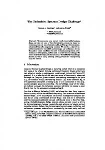
Fig. 1.
Plasma-Z 2008 Soccer Robot.
One type of robot league in the World RoboCup competition is Small-Sized League RoboCup Soccer. It proposes the problem of multi-robot working as an autonomous system in dynamic environment. The robots will play with mostly the same rules as humans play. One team has 5 robots. Each robot must be designed to meet the dimension constraints,
System Overview of RoboCup Soccer Small-Sized League.
The constraint of robot size and a range of robot function requirement implies a complex design of a high performance system in a very small package. The PCB (Printed Circuit Board) size is designed to utilize all available space by implementing all logic parts into an FPGA that contrasts to the old fashion design [2], [3], [4]. So, there are less components on the PCB and the circuits become less complicated. PCB size is reduced and it is possible to integrate all components into one main board. Consequently, there are more spaces available for mechanical part of the robot. In the past, a small-sized league robot use 4 microcontrollers to process PID control algorithm and one more as a main microcontroller. The change to FPGA brings about many advantages: 1. Due to the reduction of PCB size, it is easier to design mechanical part in a larger space available.
2. The minimized PCB uses less electronic components which also reduces the cost. 3. It is very flexible to change and debug the logical circuit in FPGA by only programming instead of modifying any hardware. 4. One FPGA consumes less power than series of microcontroller. 5. Unlike Micro-controller Unit (MCU), FPGA is faster because each module does its processes in parallel. Also, there is no need to encode and decode data for communicating between MCU and peripheral logical unit since MCU is integrated into FPGA. This article describes the overview of the robot system design for RoboCup soccer robot implementation on FPGA. There are 2 major parts presented the entire system consisted of Embedded Circuit Part and FPGA part. Fig. 1 shows our robot in the team named Plasma-Z. We participated in RoboCup 2008 in Suzhou, China and won the first prize. II. E MBEDDED C IRCUIT PART A. Circuit Overview
Fig. 4.
Robot Structure of Plasma-Z’s robot.
from H-bridge circuit to 3-phase inverter circuit that drive 3phase Brushless DC (BLDC) motors. This make the movement of the robot faster and the speed can be controlled more accurately. However, the cost is higher and it is more complicated to make a good control. The wireless communication did not change much in the circuit layout but the change was made at the selection of RF Module. B. Circuit Design
Fig. 3.
Circuit Overview of Plasma-Z’s robot.
The circuit part of Plasma-Z RoboCup team has been designed and developed continuously for more than 6 years. The PCB layout was changed and modified each year. For the circuit of the year 2008 version, most of parts are inherited from 2007 version. The major changes during past 3 years are the processor circuit, the motor driving circuit, and wireless communication module. As mentioned previously, the main processor is integrated in FPGA contrasted to the old system which was separated. This designs reduce the processing cycle time and the space on the PCB. The motor drive had changed
The circuit was design to meet all required functions of the soccer robot. The space on the PCB is very compact due to the size limitation and the space of mechanical part. It is also considered to make the PCBs easy to assemble, debug, and run in the test mode. The present circuit boards contained 4 boards which are Main circuit board, RF Receiver board, RF Transmitter board, and Shooting board. All circuits connected with FPGA are categorized into 6 parts as follow: 1) Human Interface part: This part contains input and output/display circuit . There are three inputs from 3 push buttons for resetting the system, mode selection (for test mode), and discharging the capacitor. Furthermore, a 4-bit code switch is used to get an input data of robot number and test mode selection. To show the status of the robot, 4 LEDs array and buzzer are also implemented. 2) Computer Interface part: There are RS-232 and JTAG which are frequently used to debug the programming problem and send out a long data which cannot display by the Human Interface part. 3) Wireless Communication Part: This circuit part is the path for data package to send out and come in serially to frequency modulating modules. RF ICs module used to receive and transmit data are LINX, RXM-900-HP3-PPS and TXM900-HP3-PPS. These are FM types which operate over the frequency range of 900MHz. 4) Brushless DC Motor Driving part: There are 5 BLDC motors in each robot. Four of them are used as the robot omni-directional wheels and one for dribbling the ball. The
Fig. 5.
Brushless DC Motor Diagram.
input signals from the motor are two of digital quadrature encoder feedback signals and three of built-in hall sensors.The signals from miniature encoder and hall sensors are separated from FPGA by 74LVC245A IC buffer. The output signals from FPGA to the driving circuit are 6 MOSFET gate drive signals to switch the current flow through each stator coil of the BLDC motor. The signal path between FPGA and driving circuit are separated by 74LS07 IC Buffer. The direction of motor rotation can be controlled by re-order the phase drive signals (Phase-A,B,C) e.g. A-B-C-A-B- to C-B-A-C-B.
6) Shooting Part: This system contains controller system, charging system, capacitors and solenoids. It is separated from the main board so that it can be operated on its own (Fig. 7). There are 4 input signals for this system which are charge enabling, flat shooting, chip shooting and voltage reference. Ground of the main board and shooting board is separated by optocouples. As for charging system, pulse width generated by IC 555 is used to switch the MOSFET for boosting circuit then the two capacitors are charged to 250 Volts. Capacitor voltage is controlled by a comparator logic using an operational amplifier. There are two types of shooting which are flat shooting and chip shooting. The main board generates a pulse for opening IGBT gate which enables current flow from capacitor through solenoid. The velocity of the ball is controlled experimentally by the length of the pulse for IGBT. III. FPGA PART A. FPGA Overview Hall Sensor Encoder
FPGA RF DATA IN (AI Command)
RF Module (Receiver)
Ball Detection Signal
Fig. 6.
Main Processor Module
PID & Driver Module
Driving Signals
Display Module
LED Displays & Buzzer
RF Module (Transmitter)
RF DATA OUT (Robot Data)
Shooting Module
Shooting Signal
Dribbler Module
Dribbling Ball
Ball Detection Diagram.
5) Ball Detection Part: According to Fig. 6, FPGA generates rectangular wave with frequency about 2.4 kHz to an infrared LED in order to lessen the noise problem. The phototransistor is used for detecting this Infrared signal. If the ball lay close to the robots dribbler, it will block an Infrared signal and the photo-transistor would not be turn on. On the contrary, if the ball is not there, the Photo-transistor would turn on letting the signal pass through a high-pass filter circuit to a comparator circuit. And it will be compared with an offset reference voltage. The output from a comparator will reveal the state whether the ball is ready to be shot or not.
Hall Sensor
Fig. 8.
An FPGA Overview.
The design concept of FPGA is described in this section. As seen in Fig. 8 , FPGA system is composed of 8 modules. Each module has its own duty separate from the others. There is one main processor module. A significant input in robot soccer is RF data in which is an AI command for controlling robot. The output are all the actions that robot performs which are the movement, shooting the ball, dribbling the ball, LED display and Buzzer, and RF data out. Each module is explained in the details in the FPGA design section. B. FPGA Design
Fig. 7.
Shooting Diagram.
The modules in an FPGA (Xilinx : SPARTAN3-XC3S400) are designed and debugged by using software Altium Designer version 6.5. The total number of occupied slices for synthesizing all modules is 3582 or 99%. The detail of each module are described as follow:
MCU (PID & Encoder Motor1)
MCU (PID & Encoder Motor4)
MCU (Main Control)
MCU (PID & Encoder Motor2)
MCU (PID & Encoder Motor3)
Fig. 9.
The previous version of system used multiple processors.
1) Microprocessor Module: The previous version of robot soccer system used 4 microcontrollers to process PID control and one main microcontroller as shown in Fig. 9. This uses a lot of space on PCB. By integrating MCU Nexar TSK51 in FPGA, it uses 2379 of occupied slices for synthesizing the MCU or 66% of total slices [8]. The space can be reduced and the speed of the overall system is also increased. In the program flow in MCU, the robots work in 2 modes, which are test mode and run mode. Test mode is used for manually checking the robot in order to make sure that the robot will work well during the competition. The need for test mode is crucial since the robot is very complicated and has high probability of breaking in every parts. And one broken robot in game means high percentage in losing that game. Run mode is used in the real competition. The robots cooperate with AI and Vision system. Working loop starts from receiving the AI command and ends with accomplishing the task. 2) PID and Driver Module: is one of the most important part of the system since it is used for controlling the movement of the robot. In the past, some hardware designers utilized off-the-shelf controller, such as LM629, to setup a PID control loop for each individual motor. The drawback of such approach is the unbalanced synchronization of the controllers because the programmer has to send a series of commands to each controller individually one by one. Thus, there will be time lag in the system depending on a number of controllers. Therefore, this module is constructed so that it can perform all tasks in parallel for PID control and encoder module for each wheel of soccer robot [5], [6], [7]. v1R − cos(β1 ) − sin(β1 ) RR VxB v2R sin(β2 ) − cos(β2 ) RR V (1) v3R = cos(β3 ) sin(β3 ) RR yB ωz v4R − sin(β4 ) cos(β4 ) RR In Fig. 11, PID and Driver module combine with encoder submodule, PID Calculation submodule, and motor driving submodule. Firstly, the robot receives velocity command which consists of velocities in two directions (Vx , Vy ) and one
Fig. 10.
Motion Control.
PID & DRIVER MODULE Encoder Hall Sensor
PID Calculation submodule
Encoder submodule
Motor Drive PWM
Motor Drive submodule
Velocity
Fig. 11.
PID and Driver Module.
angular velocity (ωz ) for each robot from the AI system. Then, the main processor module translates velocities and rotation command into velocity of each wheel (v1R , v2R , v3R , v4R ) using equation 1 [9]. Then, the main processor module sends each wheel velocity to PID and Driver module for controlling it. The old velocities measuring from encoders are calculated in PID module with the new velocity for each BLDC motor. That will make motor rotate with new velocity as command. Then, the output signals from PID send to motor driving submodule for choosing the gate to open in driving circuit. 3) IR Module: It functions as the ball detector.The FPGA generates rectangular wave that has frequency about 2.4 kHz to an infrared LED. The phototransistor is used to detected this Infrared signal. The detail is already described in section II, Ball Detection Part.
RF MODULE RF Input Data
CRC Checker
RF Transmitter
RF Receiver
CRC Creator
Fig. 12.
RF Input Data
RF Module
4) RF Module: can be divided into two parts as Fig. 12. The first part is RF Receiver which is used to receive RF data
from AI computer. There is a CRC checker submodule used to detect accidental alteration of receiving data. The second part is RF Transmitter which is used for sending out the robot’s data to AI system. This also works with CRC Creator for creating CRC used as a checksum in AI system when receiving data from each robot. Vx Vy Wz
IV. C ONCLUSION
Shoot Ball Dribble Ball
AI &Vision System
Send Back Command Shoot Check
Robot
Ball Detection Check Battery Voltage Accerometer Gyroscope
Fig. 13.
Data transmission between AI system and robots
The receiving data is a command data from AI system which consists of velocity in two directions and one angular velocity for each robot, shooting command, dribbling command and send back command which tell each robot when will send data back to AI system. The transmitting data is a robot’s data sending to the AI system. The data consists of kicker check, ball detection check, measuring value from gyro meter and accelerometer. The AI system uses this data to determine the strategy of play in the game. (Fig. 13). 5) Shooting Module: is used for sending pulse for charging, flat shooting, and chip shooting. AI can choose 2 ways of shooting the ball which are normal shoot and force shoot. With normal shoot, shooting occurs only when the ball has detected by ball detection part, but force shoot can be used in any situations (Fig. 14). Shooting module receives shooting
Kick Time Shooting Type
Flat Signal
Shooting Module
Charge Enable
Chip Signal Charge Signal
Fig. 14.
with the robot, not controlling the speed of rotating. A fixed speed for rotation is enough to hold the ball with the soccer robot. 7) Display Module: is the human interface for testing and displaying. Those testing are composed of IR module, shooting system, dribbler system and driving system. For displaying to user, there are 4 LEDs telling the state of the robot such as the identification number of robot, testing mode etc.
Shooting Module.
power level in the form of shooting time length named kick time signal from AI system. The chip or flat shooting signal will send out with time period of kick time. Charge enable is active when RF module has received any commands. It means the capacitors are always charged when the robot is playing in the game and the robot is ready to shoot at anytime. If charge enable is on and an IR part can detect the ball, the shooting commands can be send to the shooting part. 6) Dribble Module: uses only PWM signal to drive the speed and the hall sensor to measure the position of rotor. PID is not necessary because the aim is just holding the ball
In this paper, an overview of FPGA design in small size robot soccer is proposed with a complete description of functional modules. Compared to implementing robot control system with MCU in the past that used a lot of space in PCB, using FPGA can solve the problem and has more benefits which are reducing cost, low power consumption and processing in parallel. Also, using FPGA make the system more flexible to upgrade and debug the logic circuit. The result from FPGA implementation in Plasma-Z robots system has shown to be a very efficient and elegant way of generating parallel system of RoboCup Soccer since Plasma-Z had shown the full potential in World RoboCup Soccer 2008 and succeeded in this competition. For further development, reducing latency in the system can be conducted by optimized some code in MCU and making more parallel modules. For omni-directional soccer robot, movement accuracy can be improved by implementing gyroscope and accelerometer with more advanced control algorithm such as kalman filter instead of only PID control. R EFERENCES [1] Small Size Robot League, “http://small-size.informatik.uni-bremen.de” [2] Cornell University RoboCup, Big Red Bots. Final Design Document, Team Brazil 1999. [3] RoboCup Systems Engineering Project 2002 Liang-Yu (Tom) Chi, Wajih Effendi, Michael Jordan, Sin-Man Ko, Wei-Feng Li, Evan Malone, Shahab Najmi, Michael Schwaller. Project Advisor: Prof. Raffaello D Andrea. May 2002. [4] Cornell RoboCup Document, Mechanical Group Final Document. Graham Anderson, Christine Chang, David Chung, Patrick Dingle, Leonard Evansic, Hank Law, Sean Richardson, John Roberts, Ken Sterk, Jeremy Yim. Project Advisor: Prof.Raffaelo D Andrea, May 2003. [5] Wei Zhao, Byung Hwa Kim, Amy C. Larson and Richard M. Voyles. FPGA Implementation of Closed-Loop Control System for Small- Scale Robot, 2005 [6] Jugkree Palakawong na Aduthaya, Chirot Charitkhuan, Janjai Bhuripanyo, Distributed Control System for Small-sized Robocup Sripatum University, 2004. [7] Chirot Charitkhuan, Janjai Bhuripanyo, Rerngwut Choomuang, FPGA Implementation of Closed-loop Control System for Small-sized RoboCup, Bangkok, Thailand: IEEE CIS-RAM 2006. [8] Altium Nexar TSK51, “http://www.keil.com/dd/chip/3730.htm” [9] Sirichai Pornsarayouth, Asst.Prof. Manop Wongsaisuwan, Accuracy Improvement of Omni-Directional Mobile Robot using Gyroscope and Acelerometers, Bangkok, Thailand.