Robotics and Autonomous ELSEVIER
Robotics and Autonomous Systems 16 (1995) 5-16
Systems
On autonomous navigation in a natural environment Michel Devy, Raja Chatila, Philippe Fillatreau, Simon Lacroix 1, Fawzi Nashashibi 2 L.A.A.S. - CNRS, 7Avenue du Colonel Roche, 31077 Toulouse Cedex, France 3
Abstract This paper presents a task-oriented approach that we developed for the perception system of a cross-country autonomous robot. We introduce an adaptive navigation method, well suited for the characteristics of complex natural environments. This approach is based on a multi-purpose perception system that manages different terrain representations. This paper focuses on two perception functionalities required during navigation, along with the corresponding representations. These functions deal with the navigation planning, and the robot self-localisation; they have been integrated within the control architecture loaded on board of our mobile robot ADAM. Finally, results of the EDEN experiment, always on the way at LAAS, are presented. Keywords:
Perception; Autonomous navigation; Multi-purpose model; Natural environment
1. Introduction This paper presents several perception functionalities required for the autonomous navigation of a mobile robot in a natural environment. Many mobile robots are able to move in structured environments (horizontal ground, a lot o f landmarks: vertical lines, planar faces, etc.) [16,17,7]. For new applications (intervention in high risk zones, planetary exploration . . . . ), more complex decisional and perceptual methods are required to deal with the modelling of unknown and un,;tructured 3D environments; the only knowledge the robot can extract about its environment relies on the interpretation of sensory data, which are always partial, inaccurate and sometimes erroneous. 1Currently at McGill University, Montreal, Canada. E-mail:
[email protected] 2 Currently at Ecole des Mines de Paris, France. E-mail:
[email protected] " 3 E-maih michel, raja, filatro, simon,
[email protected]
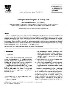
The "EDEN" experiment carded out in our lab with the mobile robot A D A M (Advanced Demonstrator for Autonomy and Mobility, property o f FRAMATOME and MATRA M A R C O N I Space, currently lent to L A A S ) , aims at demonstrating a fully autonomous navigation system in a natural environment, including perception, environment modelling, localisation, trajectory planning and execution on fiat or uneven terrain. Fig. 1 shows an image of A D A M and of its natural environment; it is a 20 by 50 meters area, composed of flat, sloping and uneven rocky areas. The robot ADAM is fitted with a 3D scanning laser range finder, two color cameras, and a 3-axis inertial platform. The generic control architecture for A D A M is organised into several levels [4]. The lower Functional Level includes modules that carry out the functions for acting (wheels, perception platform), sensing (laser, cameras, odometry and inertial platform) and for various data processing (feedback control, image processing, terrain modelling, trajectory computation,
0921-8890/95/$09.50 @, 1995 Elsevier Science B.¥. All rights reserved 0921-8890(95)00028-3
SSDI
6
M. Devy et al./Robotics and Autonomous Systems 16 (1995) 5-16
Fig. 1. The mobile robot ADAM in its natural environment. etc.). This lower level is supervised by the Decisional Level which establishes at run-time the dependencies between modules and controls their execution according to the environment context--here the characteristics of the terrain--to the requirements of the high level task and to the robot state. The canonical task given to the robot is "GO TO (Landmark)" in an initially unknown environment that is incrementally discovered by the robot. The landmark is an object known by its model, which can be recognised and localised in a video or range image. The complexity of this na,,igation task comes from the diversity of the possible situations. Then, it is not sufficient to describe the environment with only a list of homogeneous features; we must build a composite model, in which several representations will be managed together. Each one will be well adapted for a given task, according to the environment aspect: the selection of an intermediate goal on the path, the generation of navigation maps required by path planners, or the estimation of the robot position with respect to an absolute reference frame, etc. In this paper, we briefly describe these different representations and the navigation and localisation functions. In Section 2 we give an overview of the purposive perception subsystem of ADAM. Then, we focus on the decisional modules that must select the better strategy to deal with navigation planning and robot localisation. Finally, we validate our algorithms with experimental results achieved on the ADAM test-bed. More details can be found in Refs. [ 15,5,1,3,2].
2. A multi-purpose perception subsystem Several aspects make interventions in natural scenes, a difficult problem for robotics: unstructured and a priori unknown environment, poor communication possibilities (important delays or low bandwidth), etc. These constraints rule out telerobotics approaches, and point towards robots with important autonomous capacities. The robot must build and maintain its own environment representations, upon which it autonomously reasons and plans the acti-ms needed to fulfil the mission, defined only at a task level. This paper presents two functions that have been integrated in the Decisional Level of ADAM; the Navigation Planning must select intermediate goals and navigation modes, i.e. choose the best-adapted behaviour from the characteristics of the terrain that the robot must go across; the Perception Planner must select the better localisation strategy, and the sensor positions from which perceptual data could be acquired on interesting landmarks. At the Functional Level, the localisation task must refine or correct the estimate of the robot position; this task must be executed when the accuracy of this estimate provided by the internal sensors becomes too bad with respect to requirements given by the Decisional Level. The Navigation Planning performs an adaptive approach in order to always select the better method according to the environment difficulty. Terrain characteristics are very variable: there are rather fiat areas--
M. Devy et al./Robotics and Autonomous Systems 16 (1995) 5-16 cluttered or not by obstacles--and others which are uneven with respect to the locomotion capacities of the robot. Navigation on uneven areas involves fine terrain modelling, complex strategies to tackle robot self-localisation and trajectory planning, whereas fiat areas can be more easily crossed; motion planning is sometimes not necessary if the area is essentially obstacle-free. Then, the terrain model must be segmented, so that in each region, one of the following navigation modes can be selected: The reflex mode: locomotion commands are determined on the basis of (i) a target value (heading or position) and (ii) the information provided by "obstacle detector" sensors. Internal sensors give good estimates of the robot position and attitude; only correction on the heading 6P can be required if the crossed area, which has simply been labelled as "essentially obstacle-free", is very large. A 2D planned mode, applied when the terrain is mostly flat--or with an admissible slope--with some obstacles. In this mode, a 2D trajectory is planned and executed. Many measurements provided on ADAM, show that, during movements on such even terrains, internal sensors give very accurate estimates on the (~b,~p) attitude angles; so, corrections on the robot position estimates are only required on the (X, Y,0) parameters. A 3D planned mode, applied when an uneven area has to be crossed. It requires a 3D model of the terrain, on which a complex 3D trajectory is planned, and a complex localisation task can be executed. In this case, the 6 position and attitude parameters must be estimated from perceptual data. Each of these navigation mode requires a specific environment representation. Several authors [ 11,13 ] emphasised the development of modelling modules able to deal with an 3, terrain configuration, trying to recover as much information as possible from the acquired 3D data; these approaches do not take advantage of the variety of the environment. Although sometimes needed, the recovery of a complete and accurate 3D geometrical model may often be not necessary. More simple and approximative representations will be sufficient in many situations, when the terrain is mostly fiat for instance. We believe that aiming at building a "universal" terrain model is extremely complex and not efficient. We therefore chose to endow the robot with a composite
7
terrain modelling capacity: aparticular representation is built or updated only when required by a given task. This involves the development of modelling functions, each of them being dedicated to the incremental construction of an on-board environment model, by successive aggregations of local models computed from the depth maps, acquired by a Laser Range Finder (LRF) or by a stereovision correlation algorithm. All these representations are integrated in a multi-level heterogeneous model, in which all knowledges can be managed and global consistency can be maintained.
3. Heterogeneous models The difficulty of representing outdoor environments comes essentially from the fact that they are not intrinsically structured. As a consequence, any representation based only on geometric primitives (linear or second degree surfaces, super-quadrics, etc.) is difficult to build and to maintain, and introduces on the perceptual data approximations that can distort the reality. In a first step, we therefore favoured the development of simpler low level representations (polygonal maps, elevation maps, 3D blobs, etc.), easier to build and manage. In a second step, when several perceptual data have been acquired on a given area or object, more symbolic information (terrain area approximated by surfacic primitives, objects approximated by volumetric primitives, etc.) can be extracted. Another important characteristics of the representations are related to the robot mission. The environment is initially unknown and is incrementally discovered: the robot must be able to manage local representations, and merge them in global descriptions of the world. We are convinced that global representations are required [6], especially to recover from deadlocks that often appear when reasoning only from successive sensory data acquired on the environment. The key word on our modelling strategy is heterogeneous; each perception function requires a corresponding global representation. So, we must deal with the incremental construction of several models, in which the same entity of the actual world (a rock, a tree, a rocky area, etc.) can be represented in each model, by different data structures. Different representations are required in the Functional and Decisional Levels.
M. Devy et aL /Robotics and Autonomous Systems 16 (1995) 5-16
At the Functional Level, from the poorest to the richest, here are the representations required by the three navigation modes described above: • Reflex navigation: this mode does not involve trajectory planning, thus any terrain modelling, but a description (a simple 2D polygon in our case) of the area where it can be applied. The localisation task requires a global model where detected landmarks can be represented by specific geometric descriptions; a localisation procedure can be based on the extraction of 2D features, so that they could allow to estimate only 0, or the (X, Y,/9) robot position parameters. • 2D planned navigation: this mode is applied on lightly cluttered environments. The trajectory planner requires a binary description in terms of crossable/non-crossable areas, represented in our case by a binary bitmap. In the crossable zones, the robot's attitude is not constrained (flat terrain, or with an admissible slope for the robot); the trajectory is defined as a sequence of 2D positions within the crossable areas. The localisation task can rely on the same feature-based procedure than in the reflex mode, but, in this case, corrections on the (X,Y, 0 ) - - a n d also Z for sloped terrain--robot position parameters, are mandatory, because the system obviously needs to know precisely where the robot stands in order to plan safe trajectories on formerly perceived areas. • 3D planned navigation: on such areas, the 3D trajectory planner must rely on a much more complex algorithm [20] that requires a detailed modelling of the terrain, i.e. in our case, a Digital Elevation Map (or DEM), computed on a regular Cartesian grid [ 18,19]. The localisation task is based on a correlation-based algorithm (like iconic matchings proposed in [ 14,13,21 ] ); we have developed an original procedure that requires a terrain representation based on B-spline surfaces. In other papers [ 1,2], we have also proposed the modelling of unstructured objects (rocks, bushes, trees) with complex geometric primitives (3D blobs or super-quadrics). This object-based model allows us to perform landmark detection in 2D planned navigation mode, or to focus iconic matchings in 3D planned navigation mode, or might provide a "qualitative" localisation functionality, sufficient in the Reflex Navigation mode.
At the Decisional Level, the navigation planning consists essentially in the determination of intermediate goals between the current robot position and the final goal given in the parameter of the GO TO task. Different constraints can be taken into account to perform this "route" planning, depending on the context: one may prefer to execute safe trajectories from the localisation point of view, or one may choose the fastest trajectories (time constraint), the shortest (energy constraint). A symbolic description of the perceived environment is here necessary: a topological connection graph. Perception planning is closely linked to navigation planning; it requires precise sensor models in order to do predictions like: what can be perceived from a given sensor located in a given position? or reciprocally, what is the visibility area of a given landmark with a given sensor? In order to answer these questions, we must take in account the perceptual constraints of the sensor (occlusion, field of view, specularity) that must be checked considering an environment model used for the localisation task. Fig. 2 illustrates the relationships between the various representations and shows a constructive dependency graph between them. The thick arrows corresponds to the production of a structure required by the trajectory planner, either in the 2D navigation mode or the 3D one. A thin arrow from A to B corresponds to a function that builds the B representation from the A representation. We distinguish two kinds of dependencies: • Systematic dependencies: every time a representation is updated, the other ones that systematically depend on it (arrows "S") are updated. For example, every time 3D data are acquired, the global bitmap representation, the region representation and the connection graph are updated; every time a new landmark appears in the localisation model, the connection graph is updated to indicate this information to the Decisional Level. • Controlled dependencies (arrows "C"): The representations that are not always necessary are only built under control. For instance, a DEM is only required to cross an uneven zone. The top level of this heterogeneous model is a "bitmap" description of the environment, built upon the results of a fast terrain analysis algorithm. A lot of information is available in every pixel of this bitmap,
M. Devy et al./Robotics and Autonomous Systems 16 (1995) 5-16
~
~
9
y TOPLEVEL(BITMAP) (REFLEXMODE') ) f ~w'" - "~,~,~ / / / / / / / / / / / / / / ~'~ /-- //-- /-- ,/--/"/'--/" S dY REGIONREPRES~/TATION // / / / / / - ' ~ / ~ ~L/J/ L/- / / / / / / /~ x s
/
Y~,~ ~
/
.
,
.
..¢~e ~.~" : .~ i " "
~
~
9~._/q
/
~ x
/
SUPERQUADRICS ~
•
RAW3DD A T A ~ ~ ~ X_ -~ - - ~ Y
/I~
~
"
/ x
.
~_x
LOCALIZATION MODEL Fig. 2. The heterogeneousrepresentationsused in the system. such as the terrain label (obstacle, even, uneven, etc.) and its confidence level, the estimated elevation, the identification of the region it belongs to, etc. Such a structure is simple, rich and adapted to the lack of geometrical structure of the environment. The main drawback of maintaining global representations is memory occupancy, which rapidly becomes huge if the robot must go across large areas, especially when using bitmap representations and elevation maps. To cope with this, we are currently developing a "forgetting" functionality: the area surrounding the robot, with a size limited by the sensor capacities, is fully described, whereas the remaining already perceived terrain is structured in a more compact way; for the purpose of long range navigation, only the connection graph and the localisation model are kept during the time of the entire mission.
4. The navigation planning At each step of the incremental execution of its mission, the navigation planner autonomously chooses an intermediate goal, along with the navigation mode
to apply to reach it. This induces the choice of the representations it must update. To achieve this, we propose to build and update systematically a global qualitative description of the environment on which all "strategic" decisions are taken. This representation is built from successive local bitmaps, provided by a fast analysis of the raw 3D depth map acquired either by the LRF or by the stereovision rig. The global bitmap provides a terrain description in terms of navigation classes, and some other qualitative information, such as the possible presence of a landmark, the mean elevation and slope of some areas, etc. Each time this representation is updated, it is structured in order to produce the connection graph, i.e. a semantically significant model, from which navigation and perception plans are deduced. We present only some details on the construction of the bitmap and connection graph representations.
Local bitmap The fast classification procedure is performed each time 3D data are acquired. It produces a description of the perceived areas in terms of terrain classes, along with some qualitative information. It relies on a spe-
10
M. Devy et al./Robotics and Autonomous Systems 16 (1995) 5-16
Fig. 3. Discretization in the sensor frame, and projection on the ground.
Fig. 4. Classification result on a complex scene. cific discretization of the perceived area in "cells", on which different characteristics that allow us to label them are computed [ 15 ]. The discretization is the projection of a regular grid defined in the sensor frame (Fig. 3). Its main characteristics are that it respects the sensor resolution, and that it points out a "density" attribute: the number o f points contained in a cell. The comparison of this density with a n o m i n a l d e n s i t y defined by the discretization rates provides useful information concerning the area covered by the cell: for instance, it is equal to the nominal density if the cell corresponds to a fiat area. This information, along with
other attributes concerning the cells (mean elevation, mean normal vector and corresponding variances) al, lows us to heuristically label each cell as one of {Flat, Slope, Uneven, Obstacle, Unknown}. This classification procedure takes around half a second on a Sparc-10 workstation to process a 10 000 points 3D image. It has proved its robustness on a large number of different images. Fig. 4 shows the actual classification computed on the given scene; the labels have been associated to grey levels (from clear to dark: Unknown, Flat, Slope, Uneven, Obstacle). An important point is that it is possible to esti-
M. Devy et al./Robotics and Autonomous Systems 16 (1995) 5-16
mate a confidence rate on the labelling of each cell: this value generally decreases with the distance of the cell to the sensor, because of the decreasing accuracy on the 3D coordinates of a point with this distance. But obviously, this confidence rate depends also on the label itself: for instance, a flat cell containing a few erroneous points can be labelled as an "uneven" one, whereas the probability that erroneous points perceived on an actually uneven zone lead to a "fiat" label is very low. Global bitmap
This representation is incrementally built from the successive local bitmaps, in which all the information provided by the classification are encoded (label and corresponding confidence, elevation, slope). Fusion of the classifier outputs is a simple and fast procedure: each cell is written in the bitmap using a polygon filling algorithm. When a pixel has already been perceived, the possible conflict with the new perception is solved by comparing the label confidence values. This process is illustrated in Fig. 5: the area originally labelled "obstacle" in front of the first position (left image) is split into two smaller obstacle areas separated by a fiat area when perceived from a smaller distance (right image). Many experiments have proved the robustness of this fusion method. Connection graph
Once the global bitmap is updated, it is structured in a "region model", thanks to classical image processing algorithms. Regions are areas of uniform label, uniform mean elevation and uniform confidence. If no accurate geometrical information is available in the description of a region, some useful qualitative information can anyway easily be extracted, such as its surface or its including rectangle. A contour following algorithm provides all the adjacency relationships between the regions, from which a topological connection graph is built. A node of the graph is related to the border between two regions, whereas an edge corresponds to the crossing of a region from one border to the other. This graph is valuated according to some heuristics. The basic technique to plan a route in the known environment relies on the execution of an A*-like search in the connection graph. This search selects a path, i.e. a succession of connected regions that defines the intermediate goal anti the motion mode to activate.
11
5. The iocalisation function In this section, we describe different strategies used on our mobile robot ADAM to correct the robot position estimate provided by internal sensors. We do not take advantage of any a priori knowledge that an operator could give to the robot before the mission, like topographic maps or landmark positions for example [ 12,14]. Then, the perception subsystem must build an environment model with the most suitable representation for the localisation task, according to the current context-navigation mode, constraints given by the high level mission, and especially, specific requirements on the accuracy of some components of the robot position: (X, Y) position, Z elevation, 0 jaw angle or (~b, ~p) attitude angles. The localisation task must analyse the local representations (which concerns mainly geometrical knowledge of the terrain), in order to identify predefined sets of natural landmarks in the environment like elevation peaks, "column" objects (like trees), topographic features like crest lines, etc.; registrations of these features allow to achieve robot position updates, Many methods proposed for the localisation task in natural scenes rely only on geometrical modelling to deal with landmark extraction and recognition. We know from experience on robot localisation inside buildings [17,18], that geometrical representations lead to bulky models, and, after some iterations, to a combinatorial explosion. So, in our current work, when we can avoid this complexity, we favour objectbased representations, relying on a simple symbolic interpretation. At the Functional Level, several localisation methods are available; we summarise the main characteristics of each one. • The feature-based method. A "2D point model" can be built using elevation peaks detected on the terrain, or using some vertical landmarks (trees, pillars). The (~b,$) vertical parameters must be known and we can only update the (X,Y,O) variable8 [8]. The correction of Z can be risky, because the height of an elevation peak (on a sharp rock for example) can be viewpoint dependent. • The iconic method. A "terrain feature model" can be built from a B-spline representation of a DEM. At this time, we need the (0, q~, ~b) robot attitude to undertake the incremental modelling of the terrain by
12
M. Devy et aL/Robotics and Autonomous Systems 16 (1995) 5-16
Fig. 5. Two steps of the global bitmap model building.
DEM, but, if we build only the DEM for localisation purpose, we can avoid this strong assumption and compute directly a B-spline model from a local DEM expressed in a vertical robot frame (after correction using (~b, ~p) angles). From the B-spline representation, elevation peaks or points defined by a curvature property can be easily extracted [9]. These features can be given as input to two methods: they can be added to the "2D point model", and when at least two features are perceived once more, we can update the (X, Y,0) parameters, or a cooperation with an iconic matching (registration of DEMs using correlation) has been proposed in [ 18 ] to update the (X, Y,Z) variables with a better accuracy. • The object-based method. Seeing some assumptions on the perceived scene (even ground with few obstacles), we propose a segmentation algorithm to extract a more symbolic representation [ 1 ]. Ground is described by a planar or quadric surfacic primitive; for the obstacles (which correspond to isolated rocks laid on the ground), we can choose three representations: a coarse description, named "3D blob" (nine parameters: barycenter, main inertial axis and maxima radius in the three directions), a super-quadric (volumetric description, with at least 13 parameters) or a fine surfacic description (B-spline). We are currently studying the stability of these different representations, the incremental modelling and localisation
methods which could take advantage of this "object" model, but it appears that barycenters could provide points for the "2D point method", that inertial axis could allow the update of the (~b, ~p) vertical parameters and that invariant features extracted from the volumetric or surfacic description could allow a complete robot position update, like in [21]. At this time, we have integrated the two first methods on ADAM; they have been validated by a lot of experiments. The selection of the better localisation method according to the context needs reasoning capacities on some elementary knowledges, like the navigation mode, the uncertainty model of the internal sensors, the number of landmarks extracted for each method, the accuracy and uncertainty of the landmark detection, the certainty of the feature or iconic matchrags when dealing with model registration, and, finally, the algorithmic cost of each method. Investigations on the perception planning for the localisation task are on the way.
6. The EDEN experiment All the concepts and processes described in this paper are currently being integrated in the context of the "EDEN" experiment on the ADAM test-bed. The chassis was built by VNII Transmach (St. Petersburg
13
M. Devy et al./Robotics and Autonomous Systems 16 (1995) 5-16
%,. J J re ,,
Fig. 6. Iconic matching and DEM fusion.
Fig. 7. Final GEM and robot positions after four fusions.
14
M. Devy et al./Robotics and Autonomous Systems 16 (1995) 5-16
(Russia). The on-board computing architecture is very powerful (two VME racks with 68040 CPUs under VxWorks, Sparc CPUs under Sun-OS, three Datacube boards, etc.), because our final objective is to load on board all the functions involved at the Functional and Decisional Levels. In this paper, we present only results of experiments using the 3D planned navigation mode. For this sake, we have partially integrated the following functions: fine terrain modelling by DEM, localisation procedures and 3D trajectory planning on uneven terrain. The computation time needed on a sparc II Sun station to build a Digital Elevation Map is about 2 seconds; the localisation process takes about 3 seconds, and the 3D planning process needs about 60 seconds Fig. 6 illustrates the position update and the terrain model updating performed after the third acquisition. The left figure shows the extracted features in the Local Elevation Map, built from the last acquired depth image. The middle image presents the corresponding correlated points (and the correlation windows) in the current Global Elevation Map. The right image presents the new Global Elevation Map after the robot position updating and the DEM fusion. In Fig. 7, we displayed the final DEM and the updated robot positions after each localisation. The right figure shows a perspective view of the reconstructed terrain on which the 3D trajectory of the robot has been planned and executed (the grid discretization of the elevation map is
10 cm).
7. C o n c l u s i o n
We have presented an integrated multi-level perception system for a cross-country autonomous robot. This system points out several different modelling services, and enhances a lot the robot autonomy and efficiency. An ambitious experimental project, still on the way, validates our adaptive approach and benefits the development of highly demanding robotic applications, in particular planetary exploration. ] A lot of difficult tasks have nevertheless still to be carried out. For instance, the integration of a stereovision correlation algorithm [ 10] would enhance the perception capabilities, by providing dense 3D and color data on a particular area. We could then address natural landmark recognition, and estimate the
physical nature of the soil during the classification procedure. The global integration on the robot is not yet completed. We have only experimented with the 2D navigation mode [5] and the 3D navigation mode [ 19] separately. Mixing both modes with a reflex mode requires the development of "smart" navigation strategies. This topic in particluar needs to be better formalised and tested; the idea of developing exploration strategies in a topological connection graph whose arcs are valued with a confidence rate, while having the possibility of raising this confidence (by acquiring data), appears to be promising. Finally, we must improve the robot speed by enhancements on the global system performance. The key point is to adapt the complexity of the perception and locomotion functions with respect to the difficulty of the environment. We must in particular provide the robot with sensor based trajectory planning and sensor based motion control.
References
[ 1] S. Betge-Brezetz, R. Chatila and M. Devy, Natural scene understanding for mobile robot navigation, in: Proc. IEEE International Conference on Robotics and Automation, San
Diego, CA (May 1994). [2] S. Betge-Brezetz, R. Chatila and M. Devy, Object-based modelling and localization in natural environments, in: IEEE International Conference on Robotics and Automation,
Osaka, Japan (May 1995). [3] S. Betge-Brezetz, R.Chatila, M.Devy, P.Fillatreau and F.Nashashibi, Adaptivelocalizationof an autonomousmobile robot in natural environments,in: Proceedings of the IEEE Conference on Multisensor Fusion and Integration for Intelligent Systems (MFI'94), I_as Vegas, USA (October
1994). [4] R. Chatila, R. Alami, B. Degallaix and H. Laruelle, Integrated planning and execution control of autonomous robot actions, in: IEEE International Conference on Robotics and Automation, Nice France (1992).
[ 5] R. Chatila, M. Devy, S. Lacroix and M. Herrb, Perception systemand functionsfor autonomousnavigation in a natural environment, in: AIAA/NASA Conference on Intelligent Robotics in Field, Factory, Service and Space, Houston, TX
(1994). [6] R. Chatila and J.P. Laumond, Position referencing and consistent world modeling for mobile robots, in: IEEE International Conference on Robotics and Automation, St Louis USA (April 1985). [7] J.L. Crowley, P. Bobet and K. Sarachik, Dynamic world modeling using vertical lines stereo, in: 1st European
M. Devy et al./Robotics and Autonomous Systems 16 (1995) 5-16
[8]
[9]
[10]
[11]
[ 12]
[ 13]
[ 141
[15]
[ 161
[ 17 ]
[18]
[19]
[20]
[21 ]
Conference on Computer Vision, Antibes, France (April 1990) 241-246. P. Fillatreau and M. Devy, Localization of an autonomous mobile robot from 3d depth images using heterogeneous features, in: IEEE International Workshop on Intelligent Robots and Systems (IROS '93), Yokohama, Japan (July 1993). P. Fillatreau, M. Devy and R. Prajoux, Modelling of unstructured terrain and feature extraction using B-spline surfaces, in: '93 International Conference on Advanced Robotics (ICAR), Tokyo, Japan (November 1993). P. Granjean and E Lasserre, Stereo vision improvments, in: 1995 IEEE Interna~'ional Conference on Advanced Robotics, Barcelona, Spain (,September 1995). M. Hebert, 3-D Landmark recognition from range images, in: IEEE Conference on Computer Vision and Pattern Recognition, Champaign, IL )June 1992) 360-365. M. Hebert, C. CaiUas, E. Krotkov, I.S. Kweon and T. Kanade, Terrain mapping for a roving planetary explorer, in: IEEE International Conference on Robotics and Automation, Scottsdale, USA (!1989) 997-1002. B. Hotz, Z. Zhang and P. Fua, Incremental construction of local DEM for an autonomous planetary rover, in: INRIAESA Workshop on Computer Vision for Space Applications, Antibes, France (September 1993) 33-43. I. Kweon and T. Kanade, High resolution terrain map from multiple data, in: IEEE International Workshop on Intelligent Robots and Systems (1ROS '90), Tsuchiura, Japan (1990). Construction de Cartes d'El~vation. S. Lacroix, P. Fillatreau, F. Nashashibi, R. Chatila and M. Devy, Perception for autonomous navigation in a natural environment, in: Workshop on Computer Vision for Space Applications, Antibes, France (September 1993). X. Lebegue and J. K. Aggarwal, Extraction and interpretation of semantically significant line segments for a mobile robot, in: IEEE Ir,:ternational Conference on Robotics and Automation, Nice, France (May 1992). E Moutarlier and P,. G. Chatila, Stochastic multisensory data fusion for mobile robot location and environment modelling, in: Proc. International Symposium on Robotics Research, Tokyo, Japan (1989). E Nashashibi, M. Devy and P. Fillatreau, Indoor scene terrain modeling using multiple range images for autonomous mobile robots, in: IEEE International Conference on Robotics and Automation, Nice, France (May 1992) 40-46. E Nashashibi, Ph. Fillatreau, B. Dacre-Wright and T. SirnEOn, 3D autonomous navigation in a natural environment, in: SJ~bmitted to IEEE International Conference on Robotics and Automation, San Diego, CA (May 1994). T. Sim6on and B. Dacre Wright, A practical motion planner for all-ten-ain mobile robots, in: IEEE International Workshop on Intelligent Robots and Systems (IROS '93), Japan (July 1993). Zhengyou Zhang, Iterative point matching for registration of free-form curves and surfaces, International Journal of Computer Vision 13 (2) (1994) 119-152.
15
Michel Devy received his degree in Computer Science Engineering in 1976 from ENSIMAG, a Grande Ecole in Grenoble (France). He received his PhD in 1980 from Universite Paul Sabatier in Toulouse, on "Protocol Modelling for Local Area Network". Since 1980, he has worked in the Robotics and Artificial Intelligence group of LAASCNRS (Toulouse-France) on the application of computer vision in Automation and Robotics. He has been involved in numerous national and international projects about Manufacturing Applications or Mobile Robots. He is now head for the Perception Area in the Robotics Group of LAAS-CNRS and his main scientific topics concern Perception for Mobile Robots in natural or indoor environments.
Raja Chatila is Graduated in Advanced Automatic Control from Ecole Nationale Superieure de l'Aeronautique et de l'Espace (1976). He received his Doctoral Degree in Control Science at Toulouse University in 1981 (Dissertation: "Mobile Robot Navigation: Space Modelling and Decisional Processes"). Since 1981, he has been research scientist at CNRS (Centre National de la Recherche Scientifique), staff member of the Robotics and AI Group (RIA) at LAAS-CNRS (Toulouse). He has been involved in many international projects (AMR, SKIDS . . . . ) and is currently responsible for The Mobile Robots Projects in the RIA group (HILARE, EDEN). His main research interests concern Artificial Intelligence for robot decisional autonomy (Planning and Execution Control), Task-level robot programming, Multisensory perception and environment modelling, Control Architectures for Autonomous Robots, and Motion planning.
Philippe Fillatreau has been graduated at Toulouse, from the ENSEEIHT engi-
neerng school (speciality: Electrotech-
nics and Automation) since 1988. He obtained his PhD in robotics in January 1994, funded by the Framatome company, at LAAS-CNRS laboratory, dealing with perception, 3D environment modelling and localisation for an autonomous all-terrain mobile robot, in the framework of joint projects dealing with intervention mobile robotics for public safety or planetary exploration. In 1991/92 he spent one year as a research engineer at the Matra Marconi Space company, where he was involved in the Eureka-AMR project. He is currently a visiting researcher at the Department of Artificial Intelligence of the University of Edinburgh, Scotland; this post-doctoral stay is funded by a Human Capital and Mobility fellowship of the European Community. His current research interests are related to 3D perception in factory-like or outdoor natural environments, including the problems of registration, incremental fusion and structuring of the environment models, and non-polyhedral object recognition.
16
M. Devy et al./Robotics and Autonomous Systems 16 (1995) 5-16
Simon Lacroix was born in 1966 in Reims, France. He received an engineering degree in robotics for Ecole Centrale de Paris in 1990, and defended his PhD at LAAS/CNRS (Toulouse) in March 1995. His thesis research concerns natural environment modelling from 3D data, and navigation (motion and perception) strategies for an outdoor mobile robot. He has been involved in several international projects, concerning active perception for scene interpretation (SKIDS) or 3D terrain modelling and robot navigation for applications like planet exploration (lARES). He is currently on a post-doctoral year with Pr. Dudek at McGill University Center for Intelligent Machines, Montreal. His current research concerns environment model abstraction and active perception for environment modelling.
Fawzi Nashashibi received his Master degree in Automation and Computer Science Engineering in 1989 from Paul Sabatier University (UPS) in Toulouse (France). He received his PhD in Robotics from UPS in 1993, on the "Perception and 3D Environments Modelling for Autonomous Navigation of Mobile Robots". He has worked from 1990 to 1994 in the Robotics and Artificial Intelligence group of LAAS-CNRS in Toulouse, where he has been involved in several local and international robotics projects (EDEN, AMR, VAP and IARES). His mean scientific topics concern perception, modelling and localization for mobile robots. Since then, he is a researcher in the Robotics group of the Ecole Natiouale Sup~rieure de Mines de Paris.