In Chapters 6 and 7, laser-Doppler anemometry for compressible flows is discussed, ... of the data and of the measurements, on the boundary-layer edge state and the influence of ..... altered significantlv by thcedistort ios - ...... 4C VITA. VS ITA. -30. -10. 10. 30 7, 1 . 10. 30. TimelIPSl. Timlipsl. Figure 17. ...... 9.02S6'04 1.0000.
AGARDAG-315
WON
A S,.. rvey of Measurements and Measurin-g Techniques in RapidI-v Distorted Compressile TU et Tr Boundary Layers A,,po'ved fox piib1ic tec
-j
DIST;
3UTION AND AVAILAW.U*YON4 BACK COVFR
AGARD-AG-315
NORTH ATLANTIC TREATY ORGANIZATION ADVISORY GROUP FOR AEROSPACE RESEARCH AND DEVELOPMENT (ORGANISATION DU TRAITE I)E L'ATLANTIQUF NORI))
AGARDograph No.315 A SURVEY OF MEASUREMENTS AND MEASURING TECHNIQUES IN RAPIDLY DISTORTED COMPRESSIBLE TURBULENT BOUNDARY LAYERS by H.H.Fernholz Herman Fottingcr Institut fUr Thermo und Fluiddynamik Technische Universitit Berlin Strasse des 17 Juni 135 D- 1000 Berlin 12 Federal Republic of Germany J.P.Dussauge Institut de Mdcanique Stalistique de laTurbulence 12 Avenue du Gdndral Leclerc 13003 Marseille France
P.J.Finley Department of Aeronautics Imperial College of Science and Technology Prince Consort Road London SW7 2BY United Kingdom A.J.Smits Princeton University School of Engineering and Applied Science Department of Mechanical & Aerospace Engineering The Engineering Quadrangle Princeton, New Jersey 08544 United States Edited by E.Reshotko
Dept. of Aerospace Mech. Engineering Case Western Reserve University University Circle Cleveland, Ohio 44106 United States
Acceiojw hNTIS DriC
By
For
CfA&, TAB
-
A,,
.:I iy Codes
A j-ij dtor
This AGARDograph has been produced at the request of the Fluid Dynamics Panel of AGARD.
THE MISSION OF AGARD According to its Charter. the mission of AGARD is to bring together the leading personalities of the NATO nations in the fields of science and technology relating to aerospace for the following purposes: - Recommending effective ways for the member nations to use their research and development capabilities for the common benefit of the NATO community: - Providing scientific and technical advice and assistance to the Military Committee in the field of aerospace research and development (with particular regard to its military application): - Continuously stimulating advances in the aerospace sciences relevant to strengthening the common defence posture: - Improving the co-operation among member nations in secrospace research and development;
- Exchange of scientific and technical information: - Providing assistance to member nations for the purpose of increasing their scientific and technical potential: - Rendering scientific and technical assistance, as requested, to other NATO bodies and to member nations in connection with research and development problems in the aerospace field. The highest authority within AGARD is the National Delegates Board consisting of officially appointed senior representatives from each member nation. The mission of AGARD is carried out through the Panels which are composed of experts appointed by the National Delegates, the Consultant and Exchange Programme and the Aerospace Application, Studies Programme. The results of AGARD work are reported to the member nations and the NATO Authorities through the AGARD series of publications of which this is one. Participation in AGARD activities is by invitation only and is normall) limited to citizens of the NATO nations.
The content of this publication has been reproduced directly from material supplied by AGARD or the authors.
Published May 1989 Copyright 0 AGARD 1989 All Rights Reserved ISBN 92-835-0506-9
Printed by Specialised Printing Services Limited 40 Chigwell Lane, Loughton, Essex IG O37
J
ii
PREFACE A large body of data for incompressible turbulent boundary layers has been accumulated over many years by many investigators. These measurements have revealed elements of the structure of this complex flow. Three-dimensional multiple scale phenomena have been observed, and there is the beginning of an understanding of the details of the structure and physics. This will lead to more realistic models and physical understanding, which will be primary inputs into concepts of control of these turbulent boundary layers and will provide aframework to validate computations. At high speed, where compressibility is important, there is a paucity of data. The measurements are difficult to obtain and are not easily analysed. At the same time, there appear to be some possibilities for simplification inherent in -rapid distortion theory" where the turbulent structure may be "frozen" if the disturbance is of short duration. There is a critical need for data to evaluate this concept. to provide abase for models of turbulence in compressible flows to compare with imcompressible flows, to provide amore substantial base for our physical understanding, and to provide a framework for the evaluation of the extensive computations which are currently underway. The present AGARDograph is an important start on this key problem of high speed fluid mechanics. This initial work is of limited range and primarily two-dimensional but it will provide a solid base for extensions, in the future, to wider range and three-dimensional flows. It should also provide a solid base for the modeller and the computer to evaluate their efforts.
Seymour M. Bogdonoff Gasdynamics Laboratory kechanical and Aerospace Engineerig Department Princeton University
iii
PREFACE Un volume de donnides considerable relatif aux couches limites tourbillonnaires incompressibles a6te accumule au fl des ann~es par dlifferents chercheurs. Les mesures effectudes ont permis d'apprecier certains 6I6ments dlela structure de cet 6coulement complexe. Des phdnom~nes tridimensiortnels multi-&chelle ont &6robserv~s et ceux qui travaillent dlans cc domaine commencent A comprendre le detail de la structure et les lois physiqucs qui r~gisscnt cc type d'6coulement. (es activit~s devraient d&boucher sur des mod~les plus repr~sentatifs ainsi que sur la comprehension des ph~nom~ncs physiques. elements qui sont d'une importance eapitale pour ICdlaboration des concepts de contr6le de ces couches limites tourbillonnaires. et qui devraient servir de base pour [a validation des calculs. Tr~s peu de dlonnkes sont disponiblea concernant lea ph~nom~nes observes Agrande vitesse. obi[a compressibilite jouc un role important. Les mesures sont difficiles i faire et l'analyse des resultats pose des problemes, Cela 6tant. il sentblerait qu'il existe des possibilit~s de simplification qui soicnt propres la notion de "la theorie dc [a deformation rapide" scion laquelle la structure tourbillonnaire peut etre *ge[6e" si Ia perturbation eat de courte durce. Aujourd'hui. ii faut recueillir les donnmes permettant d'6valuer cc concept. constituer une base pour la moddlisation de Iaturbulence dana les 6coulements incompressibles. cr~er une base plus 6toff&e pour Ia comprehension des ph~nom~nes physiques, et c6tablir les paramntres qui permettront d'6valuer Ics grands travalix dlecalcul qui sont entrepris I'heure actuelle. Cette AGARDographic eat une premiere approche intdressante a cc problemc cle de Ia m~canique des fluides Aigrande vitesse. Ce travail priliminaire est d'une tendue limit~e et. pour Ia plupart. bi-dimensionnel. mais il servira de base solide pour de fitturs travaux. de Plus grande envergure, comprenant les 6coulements tridimensionnels. 11desrait egalcment scrsir de base pour Ics concepteurs de modec t lea informaticiens desirant evalucr leurs propres trasaus dans cc donsaine.
Seymour M. Bogdonoff.
iv
I (
CONTENTS I
Page
PREFACE Reference INTRODUCTION by H.H.Femholz and AJ.Smits
I
RAPIDLY DISTORTED COMPRESSIBLE BOUNDARY-L&YERS by J.P.Dussauge, J.F.Debiive and A.J.Smits
2
LARGE SCALE MOTIONS IN SUPERSONIC TURBULENT BOUNDARY I AYERS by A.J.Smits and J.H.Watmuff
3
SKIN-FRICTION MEASUREMENTS BY LASER INTERFEROMETRY by K.-S.Kim and G.S.Settles
4
HOT-WIRE ANEMOMETRY IN SUPERSONIC FLOV by AJ.Smits and J.P.Dussauge LASER DOPPLER ANEMOMETRY by D.A.Johnson
6
LASER DOPPLER ANEMOMETRY IN SUPERSONIC FLOWNS: PROBLEMS IJF SLEDING AND ANGULAR BIAS by M.Elena
7
FLUCTUATING WALL-PRESSURE MEASUREMENTS by D.S.Dolling and J.PoDussauge
8
GENERAL COMMENTS ON THE INTERPRETATION OF DATA by P.J.Finley and H.H.Fernholz
9
REVIEW OF MEAN FLOW DATA by H.H.Fernholz and PJ.Finlcy
10
REVIEW OF TURBULENCE DATA by H.H.Fernholz and P.J.Finley
II
THE ENTRIES by H.H.Fernholz and P.J.Finley
12
REFERENCES FOR CHAPTERS I AND 9 TO 12 by H.H.Fernholz
13
I-I
Chapter 1
INTRODUCTION
by H.H. Fernholz*) and A.J. Smits**) *) Hermann-Fbttinger-Institut, Technische Universitat Berlin **) Gasdynamics Laboratory, Dept. Mechanical & Aerospace Engineering Princeton University
This volume presents a wide range of recent work on compressible turbulent boundary layers, and it includes a listing of flow field data from recent experiments, with an emphasis on turbulence data. It may be seen as an extension of the work by Fernholz and Finley who in 1981 brought to an end the efforts of the EUROVISC working group to collect and to discuss all compressible turbulent boundary-layer data available at that time. For that purpose data were presented in a standard format and the data collect'on contained a total of 77 experimental studies edited in two volumes (AGARDographs 223 (197,) and 263 (1981))*). Twenty-eight of the experiments reported turbulence measurements, although the data were rather limited in extent, and in some cases of doubtful accuracy. A third volume (AGARDograph 253 (1980)) provided a commentary on the mean flow data, together with pertinent remarks on the theoretical background including the effects of normal pressure gradients and boundary-layer length scales. A discussion of the turbulence data is provided in AG 263 (1981) together with remarks on experimental design and technique (for example, Hot-wire Anemometry by V. Mikulla). To avoid extensive repetition we have assumed readers have access to these three earlier volumes, and we will make frequent reference to them in this fourth volume. Since 1981, there has been renewed interest in the behaviour of high-speed compressible flows with particular attention being devoted to the understanding of shock-wave boundary layer interactions. There exist three review articles which deal with different aspects of this problem. After the first experimental paper in the subject by Ackeret, Feldmann & Rott as early as 1946, it was Green (1971) who presented the first review paper. This paper included both a discussion of the physics and of an integral calculation method and can even today be regarded as an excellent introduction to the field. A review of both theoretical and experimental investigations by Hankey & Holden (1975) laid emphasis mainly on hypersonic flows up to Mach 14. The extensive numerical work performed since that survey has been reviewed recently by D6lery & Marvin (1986), though the latter of these AGARDographs concentrates on the supersonic range with M6 < 4. More recent experimental and numerical work may be found in the Proceedings of an IUTAM Symposium (Delery 1986) while AIAA, ASME and APS conferences have seen a rapidly expanding number of contributions in this area. New turbulence data describing the development of the turbulence field across the shock/ boundary-layer interaction have become available and they make up a sufficient number to prompt the issue of Chapters 9 to 13. This would not have been sufficient material for an AGARDograph but in planning this particular volume it soon became clear that it would be desirable to augment the compilation and discussion of data in the mean flow and turbulence field with some other aspects of compressible boundary layers. The choice of topics was shaped on the one hand by a desire to fill gaps which had been left open by the previous surveys and on the other hand by a perception of what the important but perhaps more specialized topics were. Only one topic, computational aspects of high-speed flows, was specifically excluded, on the grounds that the review of D6lery & Marvin (1986) made additional efforts on our part unnecessary. In all other respects the items selected represent an unavoidably biased choice of subjects, mitigated perhaps by the fact that the individual authors have based their work on direct experience. The subsequent chapters are not meant to be a review of their particular areas; rather, they were meant to introduce the reader to a new area with sufficient background material. The primary attention is focussed on flows which have been over a relatively short streamwise distance. The choice of the subject of this volume was natural in that most of the We use the term "rapidly distorted" rather loosely without
*)
References are given in Chapter 13.
disturbed by strong perturbations, these "rapidly distorted" flows as recent data belong to this area. necessarily implying that they can
1-2 be described using "Rapid Distortion Theory" (RDT). In fact the next chapter, Chapter 2, attempts to specify under what conditions it is possible to apply RDT to compressible flow, and to describe the recent work in this area. In more general terms, many of the flows presented in the data compilation of Chapter 12 and some in AG 263 were subject to the effects of "extra rates of strain" in the sense used by Bradshaw (1973). In particular, the effect of bulk compression or dilatation is of interest in that it appears to influence tho turbulence directly (Bradshaw 1974). Some recent evidence for the effect of bulk compression is discussed in Chapter 3. This chapter provides the first review of large-scale motions in turbulent compressible boundary layers. Chapters 4 to 8 are all concerned with experimental techniques. Accurate measurements of the wall shear stress in compressible flows with pressure gradients are very difficult, since floating-element balances cannot be applied easily and since the problem of determining a calibration curve for Preston tubes in compressible boundary layers - as addressed by Peake et al. (1971) - has never been properly resolved. Furthermore, Fernholz & Finley (1980, 1981 and 1983) have shown that the transformed logarithmic law of the wall does not hold in highly perturbed flows of the type encountered in this volume and that it takes a rather long distance downstream of reattachment before a Preston tube can be applied again. In Chapter 4, a new technique based on the time rate of thinning of an oil film is discussed, and it promises to be a useful technique for strongly perturbed and possibly three-dimensional compressible boundary layers. Techniques for measuring the fluctuating mass-flux, velocity, temperature and wall pressure are discussed in Chapters 5 to 8. The primary emphasis of these contributions is to identify the strength and limitations of these experimental tools. For example, in Chapter 5, constant current and constant temperature hot-wire anemometry are compared, some general guidelines for correct operating procedures are developed, and the accuracy of each system is assessed. In Chapters 6 and 7, laser-Doppler anemometry for compressible flows is discussed, with particular emphasis on the most popular counter-processing techniques, together with some warnings on the sources of ambiguity and error. Another common experimental tool, the wallpressure transducer, is considered in Chapter 8, where some strong conclusions are drawn regarding the overall accuracy of tile currently available instruments. The data are presented and discusscd in Chapters 9 to 12. General comments on the interpretation of the data and of the measurements, on the boundary-layer edge state and the influence of pressure gradients, especially on the determination of the wall shear stress, are given in Chapter 9. Issues which deal with the physical interpretation of the data and the influence of eferred to Chapters pressure gradients and shocks on the development of the boundary layer are 10 and 11. Chapter 10 deals with a general assessment of the mean-flow data, and Chapter 1I deals with the turbulence data. Finally, the data themselves are presented in Chapter 12 in a format similar to that used in AGARDographs 223 and 263. The experiments are described in ENTRIES of which 59 will be found in the first volume, AG 223, 18 in the third volume, AG 263, and 12 in this volume. These are referred to all four volumes by a reference number such as CAT 7201. In AG 263 the 18 studies are distinguished by a final S, and in this volume the CAT number is followed by the letter T. AGARDograph 223, also contains introductory material designed to assist users of the collection which should be consulted by anyone proposing to use chapter 12 in this volume. It has not been possible to print all the profile data in "hard copy" form, so the ENTRIES contain only a selection. The full profile listings are on floppy disks which are available upon request (see next page). No microfiche listings are supplied with this volume, since past experience has shown that was not very useful.
it
It is our hope that this AGARDograph will help to stimulate experimenters to odd to the data so urgently required in this area, and to encourage numerical workers to test their codes against the data presented here. We especially hope that the turbulence data, though still scarce, will be used to improve existing turbulence models.
Acknowledgements: As always we must first give our thanks to all these who have provided us with data. Theirs is the hard work, often over a period of years, which we presume to criticise, in the belief that we are competent to assess it. In the preparation of this volume we owe a particular debt to E.U. Schade, who has resuscitated our geriatric data-handling programs and continues to provide intensive care as needed. We thank Frau L. Lindemann and Frau I. Gereke, of the Hermann-F6ttinger-lnstitut, for preparing, respectively, the written text and the very large number of figures. The AGARD executive in Paris, M.C. Fischer, has been a constant support, and we have benefitted throughout from the active interest of Eli Reshotko as AGARD editor. Finally we thank D.C. Damant Esq. of the Garrick Club, London, who has again provided the motto for this fourth volume: "Although this may seem a paradox, all exact science is dominated by the idea of approximation. When a man tells you that he knows the exact truth about anyth~ng, you are safe in inferring that he is an inexact man." (Bertrand Russel).
I-3
PROCEDURE FOR OBTAINING THE FULL PROFILE DATA LISTINGS FOR AG 315 The full profile data listings which have been compiled and discussed in this AGARDograph are available on 5 floppy discs on file at various National Centers as listed below. These floppies are 5.25 inch size and are formatted 1.2 MB. They are written to by using an IBM compatible AT personal computer with MS-DOS 3.20. Specific details. costs and procedure, lot obtaining a copy of the floppy disc set varies from one center to the other, so interested pa, tits must contact the appropriate location within their country or a center most geographically convenient. Etat-Major de La Force Aeriente
National Aerospace Laboratory
(VSL/AGARD) Rue d'Evere B-1140 Bruxelles
Attn: Library P.O. Box 153 odOD AD Emmeloord
BELGIUM Person to contact: Major N. July Tel:32(2)243-4923-Telex 21339 BE-PHQ-
NETHERLANDS Person to contact: Mr. C.W. de Jong Tel: 05274-2828-Telex 42134 nlrbb nt
Telefax 011-32-2-243-5703 Norwegian Defence Research Dept. of Fluid Mechanics Technical University of Denmark
Establishment (NDRE) Library P.O. Box 25
Building 404
N.2007 Kje[ler
DK Z800 Lyngby DENMARK Person to contact: Dr. P.S. Larsen
NORWAY Person to contact: Per Ekern Tet:(47-6)807129-Telex 21682
Tel:02-882222 ext:4732
Tetefax 06-807212
Telex 375290THD/ADK Telefax 02-882239
Aeronautical Engineering Department
Fachinformati nszentrum Karlsruhe 0-7514 Eggenstein-LeopoLdshafen 2 FEDERAL REPUBLIC OF GERMANY Person to contact: Gerd Tittibach Tel(49)7247/82-4991-Telex 17724710
Middle East Technical University P.K. 06531 Ankara TURKEY Person to contact:Prof.Dr.lng.C.Ciray Tel: 2237100/2471:2472:2431
Tetefax (49)7247/2968
Telex: 42761 00TK TR Tetefax: 2233054
O.N.E.R.A. - DED B.P. 72 92322 Chatillon Cedex FRANCE
Defence Research Information Centre Kentigern House
Person to contact: Mme F. Lhutlier Tel:46-57-11-60-Ext. 29-24
Glasgow, G2 SEX UNITED KINGDOM
Scientific i;brary- Air War College Deketia Air Force Base
Person to contact: or. H.M. Morgan 4 Tel: 041-228-2 35-Tetex:779699 TeLefaA:0..-22-e,46 or 2119
Dekelia Attiki GREECE
NASA Scientific & Technical
Person to contact: Major Papadimitriou Sotirios Tel: 2466461
Information Facility P.O. Box 8757 Baltimre Washington International
Aeronautica Militare
Airport Marylaryl 21240
Ufficio del Delegato Nazionale alIAGARD Piazzale K. Adenauer, 3
65 Brown Street
U.S.A.
00144 Roma/EUR
Person to contact: Joseph Gignac Tel:301-621-0204
ITALY
Telefax:301-621-0134
Person to contact: Colonel P. Marconi
2-I
CHAPTER 2 RAPIDLY DISTORTED COMPRESSIBLE BOUNDARY-LAYERS by , A.J. Smits
, J.F. Debibve
J.P. Dussauge
* I.M.S.T., U.M. Universitd-CNRS N*380033 Universjt4 d'Aix-Marseille 1I, Marseille, Frane **
Gas Dynamics Laboratory, !rinceton University, Princeton, New-Jersey 08544, USA.
1. INTRODUCTION if suddenly perturbed boundary lavers, two esteese
In studying the response
is
ti,.
.,t;'.t
identified : (1) Perturbations where the effects diffuse slowly throuelhthe bondary i i
r,
I
-ti
I!, ,li t'-+ .
-t,
the ven fit-ld,live,--
Typicaliv,
able to the response tine of the larce eddies.
-
preserving part of the laver is wonfined to n int-rnal liver. 12) Perturbations which el1ong-
nd trbulent fields immediately 1,',
the mean
ti ,.saipli-,
The sudden application of a pressore gradiest, ti ths
depending on the stLreIgth
affected bs the perturbti on ( [I-ienl,
f p,returbativn.
t,'th
,Ihara
the tiihl tr
'cie
departures
197h,
Omits .iii'X';-d.
:.,diarelc ti d ,I n id
in the so
The dit.cttiI
teristic time sle
is
e; i"
10851. In
w,
!i ii
,i'ntrist. i.'nii.
,,ftile turhiilest cddies.
is ii s ioernedl by
rom in unchanged sn-linsar st.Pt-
"strong" distltion where
t
: r-
Is
if 'a'
t
i
this
-,s,
it 1
.1
Tt
t:.
i. ",, I v,
t
t
l
sr
will n t livtr
,r reas-is
'sir.
sit,
t
ti aI
i,trt st '
'
sie,
.
drsse di.insito ,
Isear p
Fho basic theory was deer.lcprd hs Rib
i!er, ,
r, 'rri
ilt,
Ie ties,
d
th-
ii
fiirthermie,
s tl,
-- '
Inear set of es(atis is.
-bulere
t' :r.
t,
tne hdir-
iff0ertth, t rbt. , ' It ill P
tE. on the
it i,
ste,,vlev with 0t, 'ic
le,interacts
r .and lii'
istropic turbulence in an irrtational mean fiw. Moffatt (1967) rxoi-ple,
ir-
iss
TRD ow s le-ve l fed I- predict the cvoluti onf trl,
Reid Dist'rt ion Tlieor, I,,en
,-
is ,
and the
,yer crws sI,wl% oitil evetntll1, the w!ol'
regin near the wall . This inte rn
,
1,: '
.i pertr
prissr,
Wliei th
pressr, gradirt.
Oria
,f the f!lw is at lirst uinatti- tid,
turbulence in the onter part
is very strong, the changes
io
and townsend (1970))
r 19
'
1l1- tie','e
and sibsqieot
BIath l
r
ill
,
' 1"'1-
I ' s.-s,-':Ir, ,
o was later c-t-snd d t, Iie r f's diveloipienit s ted Li-
id, -ri, tv it
tions. The papers by Hunt (1977), lownsend (1980). Canbon (1982), and the recent reni
,w S ' iIl
e, . fr ipl ia1987
provine a comprehensive picture of the current status ci RUT. What seems pairt iilirl s en,ourigaingis th obset-tiv that depite the strict limits on the appliability useful
f PDT. the theory often gives qal itaitisel%
resslts outside these bounds, as well as providing uisefulgiidelins tfr distorted ;tro(tir. -,-lellin.
(Savil l, 1987).
Most of the work in RDT has been confined to incompressible flows. Yet, very attractive for the application of RDT. Changes in the meat.Cit
ca
ompressible flows trepotentiillv --- ,
over ver
short distances,
much shorter than is possible in subsonic flows, and the limits of RDT can often be more easily satisfied. For example, when a boundary layer passes throngh a Prandtl-Heyer fan or a short region of compression, including the case where the layer interacts with a shock-wave. I!- perturbation can occur over a distance comparable to the boundary layer thickness. Typically, the pressure gradients are
tmch stronger than the
other stress gradients outside the viscous sublayer, and it is to be expected that RDT methods are useful in the analysis of these flows. Recently, there has been considerable new interest in applying RDT to supersonic flows. The case of an irrotational mean flow and an initially isotropic turbulent field passing through a Prandtl-Mever expansion was considered by Goldstein (1978). Later work by Goldstein (1979), Anyiwo and Bushnell (19841, Debiive (1983) and Dussauge and Gaviglio (1987) has notably esxend~d this area.
(1982), Zang et al.
Before
,nmat
I IcInsfom
iciteg
in
aton
tbrev-diniens ionalI
what we
bhus the
on formal
in
emplosved
ra the r
evalutri - ,
i1977).
Bent
are not
mainly
Wi thc sac 1
icc supe rsonicI iou spec,tera. T11,-
the Reynolds
t,
vc
geneei
stress
tercos involving p res--..
because
This latter
enact.
i s noe
the assoc iat ed
than
Al ter
are deduc ed.
th is
inentalI wo rk
appri,
whe,-
sac.in."
tie
the P esit-Ids stress
WIcT a reunsed to approx inatr
in
terms
Final ly,
tions. ncd the
hection 6,
of
tens
1! RDT
-sdcibA ticI
An attemlpt
is
on che mean
the application
rapid
of
into, Iseec
classed
aid
and
e'ccations
I
e-
n- t
t,-
ip;yr-cnmatc-n ir,
11c
-ncsicr
tecurrins)'c nd -i
fcc Ids,
melt' o
acer
n-cthe. Paneii-
three groups
-
5 to cl
flccctuctcscc
distortion
based
aoalyses
cilosure (RDA).- These
in Section
made
he
1BPS),
IPIIT and PDAI),
interact ions
sc'cccd-rdee
placed
I .h
tic, 1.c
Csac
-
ire, discussed.
Ipplicabil it,
IF SHFEQtcUATIONSi lIp MtOsTO
qcctiurns
in-ar
flowsc(an
compressible
tlce ectcationu of notion
shoe b/torbsl ene
study
respectiselv.
lihfINEARIZATIOiN L lerytice
to
the restrictions
cf
in
limit,
distorted
rapidly
transport equaic-os to obta in 3 and
secLItins 2,
in
Iinearunatians of
rel at ions
Peynold 5 stress
assles
work
ticecrotical
jump
Bui.oniot
-
pointed ant by
as
st resse s
Unfort unatelyv,
rapid distortion approxinations
fer
t kbin
toI the ReynolIds st re ss
Shear
tbe
ini ts o i-eper
the
RKcA rlid.
and
term RDA.
analoses based
in
Moreover ,
Hlene, lice solutions
limit ing processe's
and
f low.
the Pnyno ILds stress
straightforward,
tlscrstions msu't he model led. arguments
Spec if ied .
closure needed
of second-order
a re not
ecquationis
energy or
i sa shear
more a ttrac t inc to con side r
it
sitnplifi-ttionu
k mnet i. oIust
be
Theory)
linear i7ing, the inamentom equat ion,
spec ta
t urbul ent
space., tbeI
number
tbe LIPStrein flow
known when nab e
wane
Distort io:.
(Rapid
Pl
obtained by
it-
th rve-dinenojionalISpectrra relatIed
t he cacltinIg an
in itialI
t be
the eqsat ions
InI BPS,
ions).
t he Fose , -
a .,ethad,
'-,Ietwecin
should make a dint inecon
prccceedinl
Distortion A-
,-an -. el
c) oticcn
Mbi-
--cs.i
tituc5iscric dancping,
the
licceaci-c
If
eIffc'
l
when
ecrs
cit
-cr-
d-is-cd
crq-.-litic-
Il-s-
turbulent
air inccmpre-ible
Is, the distcrtionmof
by
Icecc c-- a
dclctiti-'
I.
tic-sin
bc-
p
. o--ii s
severcl
flow,
-,'
,
ti,-n's-lI 'c.cc
irccl
-
cr
tlcenlc-linect acelera1tics
,
clt tee OIL
d
t
!ctcfi.
isea, ,r terms.
dampiccg
li 'i-o'sc has 'I l
irc- e,
tita
time,
ictcses
which
the
p'-
L,.
them
Td =fcC.
The effec ts a
letation
t
crantse
foe a ficethcc
the time
the
significantlv
enample,
the
-
rate
'if
q-'
where
c
II
Tce
'nO it i-o
o5f the non-I ioca r is
-
will
he asumed
that
andi
in
L-'m tant
-c 1
"lv
time derivative
terms nay
limied bs
where
T
is
the appropriate
Eulerian
is
ard It
thi' diutotticn
(I,
time
scale
T
d
snail
lnc4 as St
-- f the- lare
Ind
11cr' dict
tmIIi
m
scc
t
not
is
eddie-s
a Irce, tua t iin4 ve Ics ityv st Icale
v I't U,
ti
rung,
InI high
small.
clueing The
ticonolds
Litreneeo-comtacnin-:
a time
I
con
Ir ruct h
cit the
the cccn.ploccts
Of ticc
P1 cccating
.-
,A
j
An.
n is
c-nsideringc
3:
u
the time derinotime
we
ab5cci the
of
t
bee
;
is dominant,
iotion
hich
s
the- con-
ase'
encegs-, -c
as
I '-c
app1lced dccrtng
mad iq
scal
1 coic
r ipid,
is
as
is
h)i.
hcction
same
epsacion cit not iccn the non-l ine ar accveIerat Ion tenm need S the
-cnoids nombers,
t'0-distccticcc
teecin
is
wlcse:
tracefor
l,th
hLs,
hIts
cecclcle.
T,,
megie~ted
1-'m' be
T,-~
,
if
itga!
Lide
t It
F oe snallI
JiscssecI
in ihc
cnol Ce
the citergy
larce,
thcedistort ios
by
e
bII
visioucts' mac
citturhiclenic
di-scsion;.
is
Fca or th b--eev-ontaiernc stctcccc
cs ot
rfi-t Sc
ceclce
c-nrtgv dissipation
-
,that
tlcc'
time -sAle
sale
1h/lcc'
T,
Othi small- et
f-c
numb-c ,
rangc- base cc la-rc-sernip,
floiws
them
nole
a chatac teecucic
hec lion 6
reus.ed as
ber--pr
celc Pc-'d,
dissipat inn
tCc T"
altered
important
crccrg,
of
Ptyn-ciduoccmber pacid
is and
dctiices
(see
ncumber and
sa
Xs
order as
the other
t-c hev small
terms.
compaired to
To
obtain
any one
lnea
a linear r
term.
If
requirec
tine
scale. For
flews
where
T
p'/P
o The resulting velocity is given by :
a IIs
s'
giad Bo
s~ grad R.
+
X
,
grad 4
where three contributions can be identified : a transported part, a thermodynamic part and an irrotational part reied to pressure. Note that this result is valid for unsteady mean flows. b)
if we add the condition of mean flow steadiness,we obtain iso-energetic
flows where grad 8.
related to the other variables by the Crocco relationship. We obtain the following equation for D 9-
di(
gradw
=
div
o(s' I2p +
can be
c
"I)]
2o
4 and
w' 1 =
' I
- Stl
This solution was proposed by Goldstein (1978).
c) The following conditions can be added :
div Pov'
Either
=
0
1-
=
0
r, the sound speed is taken to be infinity. Each of these assumptions cancels the propagation term in the equation for Y , and we obtain : div (p. grad ')
- div Po(
2fp +Ix
Wl
with
oI
w'
In this case, the distributions of p and s' can be inhomogeneous. d) Finally, a limiting case is obtained with the following assumptions - irrotational mean flow - Homentropy
S1 Z 0
grad so = 0
- Uniform mean density
grad 0o = 0
- Unsteady mean flow - div
u'
=
0
The density is uniform in space but it is time-dependent. tions :
(D/Dt)s' = 0
s' and p' can be non-zero, but satisfy the rela-
1'6s' grad B0) = I
and
The equation for ' simplifies to the expression
* -
5 V'= ') Ii
with
v
V I
grad
This is similar to the cases studied by Ribner and Tucker (1952) and by Hunt (1977), using a different solution technique. Hunt used it to model the practical case of the compression cycle of an internal combustion engine.
3. SHOCK/TURBULENCE INTERACTION METHODS
The results quoted in Section 2 belong to a class of studies where the solution of a linear set of partial derivatives is calculated. Another class of linear methods is used to study shock-turbulence interactions where the shock relations are applied to turbulent fiuctuations of small amplitude using Fourier representation. The first example of this second class was developed by Ribner (1953). approach can be found in Anyiwo an
Bushnell (1982).
An exhaustive review of this
These authors also present probably the most complete
calculation of the linear amplification and generation of turbulence through a shock wave. Acoustic waves, entropy waves and vorticity waves were examined. The amplitude jump relations obtained as in McKenzie
L
._
-
2-6 and Westphal (1968) were deduced from the linearized Rankine-Hugoniot relations, and for the dispersion jump relations
the frequency and the tangential component of the wave number vector were assumed to be
continuous through the shock. In addition, the "rippling" of the shock due to harmonic incident perturbations was taken into account. The results showed that the linear mechanisms can contribute significantly to the amplification of incident velocity fluctuations, to the generation of turbulence by interaction between the shock wave and the upstream entropy fluctuations, and by externally induced shock oscillations.
All the methods described in this Section, and in Section 2 , have used linearized equations and Fourier representations, and therefore belong to the domain of RDT. As indicated earlier, there also exists a class of methods where rapid distortion is used to obtain second-order closure of the Reynolds stress equations. These RDA methods were applied to shock/turbulence interactions by Debieve (1983).
Debieve defined a transport invariant relative to the Reynolds stresses, and developed "shock formulas" for the stress evolution through a steady shock wave. Turbulent source terms that modify the transport invariant could be taken into account if they were continuous through the shock, or if they varied like a Heaviside function. No explicit hypothesis on the nature of the mean field and of the velocity fluctuations was required. However, a better description of the source terms would probably require Dirac functions source terms. This work uses some of the hypothesis required by ROT. In particular, it is argued that as the distortion is very rapid through the shock, the dissipation rate and the inertial transfer are unchanged and then do not contribute to the evolution of the Reynolds stresses. This analysis leads to a particularly simple expression for the amplification of turbulence by a shock wave. The result depends on the orientation and strength of the shock wave, and it is given by with tensors, N
is the
K = I - [E] N*/U2N UN
, where
T1 and T2
is the velocity normal to the shock,
unit vector normal to the shock, and
Na
:
T 2 = K*TI K
are the upstream and downstream Reynolds stress [JJ
is the jump in velocity across the shock,
is its transposition. An illustration of this formula
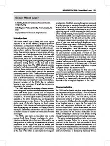
is given in figure 1, which gives a polar representation of the Reynolds stress upstream and downstream of the shock. The vector OM has a magnitude equal to the variance of the velocity fluctuation and a direction given by the unit vector m. Note that 6M - ( '.n )2 and sc' - OP - OQ The initial state correspond to an isotropic tensor and is represented by a circle. The diagram shows that the amplification through the shock is a maximum in the direction normal to the shock.
M
-
C.0
Figure
4.
1: Evolution of
the Reynolds stress tenser in a 6*
compression ramp flow.
SECOND-ORDER CLOSURE FOR SHOCK-FREE FLOWS
In many distortions of supersonic boundary layers, the turbulent fluxes can vary significantly over very short distances. Since the anisotropy of the turbulent stresses can radically alter, simple closure hypotheses are no longer adequate. rne approximations used in RUT for second-order closure then become very attractive as a means for describing the Reynolds stress evolution. As emphasived by Hunt (1977), rapid distortion are mainly observed in the fluctuating pressure terms, that is,
the effects of a
the rapid part of
the
2-7 pressure-strain terms and the pressure-transport terms. The influence of a rapid distortion on the pressure transport has not been explored in great detail for second-order closures. Some examples were given by Oh (1974), Brown and Roshko (1974) and Vandromme (1983) where most of the attention was directed towards the effect of mean compressibility on the rapid part of the pressure-strain terms. In particular, the effect of a compressible mean field on incompressible turbulence was examined by Dussauge, Gaviglio (1987) and Jayaram, Dussauge and Smits (1985) who applied RDA to the Reynolds stress equation
to predict the evolution of the turbulent stress tensor in rapid expansions
and compressions. They assumed that the turbulent field was essentially solenoidal,that is,
div u' = 0.
In this case, the rapid part of the pressure strain can simply be adapted from low speed formulations by replacing the mean velocity gradient by its deviatoric. The results of the calculation were in reasonable agreement with the experimental results.
It is rather difficult to specify the conditions under which the hypothesis div u' = 0 can be used. An attempt can be made for zero pressure gradient supersonic boundary layers. In these flows, the temperature fluctuation level
1t 2
(8'---) /e is generally much larger than the wall pressure fluctuation level (p',) /2/_w
tf it is supposed that this is true in the whole flow, and if the Lagrangian time scales of temperature and pressure are of the same order, div u'
is only produced by the heating due to viscous dissipation and heat
conduction. This result assumes that there is no significant contribution to the fluctuations by shocklets in the turbulent motion. For small fluctuations in the energetic range, a simple expression can be found -
div
'= -
C
'
e '
Gpe a
2cO 6
e
2 y02
0
(see, for example, Dussauge, 1986). By assuming that c and Ee are linked as in low speed flows, and by considering adiabatic flows in which the Strong Reynolds Analogy relationship applies, the order of magnitude of the ratio
u-/A S(div u')/
Y_
3
)3 m
sM 1
2 u"
y ,I )M (y-
where m is a Mach number related to velocity fluctuations, that is, m = ( of proportionality in the expression relating e0 to E6 , i.e. that in most practical situations
(9'/6)(y-1)M2(u'/U)
div u'/(u'/A) can be given as follows
div u'
R
.
2
jyI
) 1
/a , and R is a constant
0.4 . The previous expression indicates
is probably small in supersonic (but not hypersonic) zero-pressure
gradient boundary layers, and then Lw-speed models can be used. On the other hand, in compressions where shocklets can appear the usual second order closures are probably not applicable. Finally, it should be emphasized that there exists no complete model taking in account these "direct" compressibility effects.
5. St MARY OF PREVIOUS WORK
The rapid distortion work in compressible flows is summarized in Table 1. In each case, the limits of applicability are given. For Anyiwo and Bushnell's study (1982), where a plane shock wave with an upstream uniform mean flow was considered, the mean flow is irrotational and homentropic on both sides of the shock wave. In Dussauge (1987) and Debieve (1983), no particular hypothesis was required for the mean field, although the application they considered had a two-dimensional oligotropic mean field. In addition, no further hypothesis was required in their analysis to deal with the entropy fluctuations.
In Table 1, the experiments presented in Chapter 12 are indicated by the shaded areas. All the mean flows are two-dimensional. The properties of the fluctuating field, however, are not clearly defined. If the flow is not hypersonic, it is likely that the condition of incompressible turbulence is a reasonable approximation for zero pressure gradient flows (see Section 4) and isentropic expansions and compressions (Dussauge and Gaviglio 1987, Jayaram, Dussauge and Smlts 1985). This assumption is probably not reasonable in interactions with a strong shock. In a similar way, it is difficult to define the nature of the entropy fluctuations in these experiments. Since the time of flight is small in a rapid distortion, it seems that the specific entropy should not change significantly, except through the action of a shock.
2-8
HUNT 1977
X
a2 f 0
0
RIENER & TUCKER 1952
GOLDSTEIN
X
X
X
X
Ds'/Dt = 0 sa
o
DUSSAUGE
DEBIEVE
1981
1983
piecewise
no
no
X
X
hypothesis
hypothesis
X
piecewise
on the
on the
1978 1979
steady
homentropic
ANYIWO & BUSHNELL 1982
X e
s,, =K
.p~fe
. .
4*
Ds'/Dt
y
.
:'I M
tvn
I
*Wtj'
w..
0
'ARX
isotropic
K
X
X
X
-..
.
Table I
unspecified
.otrop.c .. .,
Some contributions to rapid distortion problems in compressible flows.
Is summary, Goldstein's work gives the more elaborate solutions of the compressible linear problem, whereas Anyiwo and Bushnell's results underline the basic physical problems to be examined in a shock /turbulence interaction . The details of the analyses of Dussauge and of Debieve are less exact, but they provide formulations more easily applied to practical situations or to laboratory experiments.
6. DISCUSSION Here, we discuss to what extent the flows presented in Chapter 12 can be described by rapid distortion considerations. Some answers can be given by the conditions defined in §2. It should be noted immediately that we are dealing with boundary-layers, i.e. flows with a viscous sublayer where the Reynolds number is low. Clearly, RDT cannot be applied in this zone. A second consideration is the existence of a region very near the wall (at about
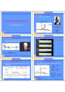
y 015, say), where the turbulence intensity can be very large, so that the small fluctuation hypothesis fails. Hence, only the evolution of the outer part of the layer can be considered by rapid distortion concepts. The time of distortion is often very small. In the case of an expanded boundary layer (Dussauge and Gaviglio, 1987) the ratio q'L/UA was about 0.2 for y/6 = 0.3 . Similar values can be found in compression ramp flows: in the flow sketched in Figure 2, the time of flight through the leading shock is very short. In the case when the flow is separated however, a continuous compression fan follows the leading shock. In this case, the interaction length is increased, and the distortion becomes slower. A typical value for y/60 0.4 in the 24' compression corner studied by Selig et al. (1987) is q'L / UA
'
0.4
for
y/6
=
0.4
2-9
5hock unsteadiness
.-
5eporoted zone
Figure 2 t Scketch of a typical interaction These estimates are questionable, because they use the upstream values of the turbulent scales. Yet, the rate of dissipation and the rate of energv transfer can be modified by the distortion. In expanded flows, the effect of mean compressibility is to shift the energetic range to the low wave numbers, i.e. to the large wave lengths. In contrast, in a compression, the wave numbers become larger and the energy containing range is brought closer to the dissipative range. Therefore, the energy transfer in compressions can produce non linear effects and limit the range of validity of the RDT.
This point however is probably not critical: if condition (3) is fulfilled, the production of turbulence (or of Reynolds stress) is much larger than the initial energy transfer rate. If this rate changes slightly in the distortion the analysis will still hold, if the order of magnitude argument remains unchanged.
The main danger of an extensive use of the criteria defined in §2 is that they postulate that any transfer of energy takes a lng time when the Reynolds number is large. An interesting peculiarity of the supersonic flows is that in a short time small scale turbulence can be created. An example can he found in Husaini, Collier and Bushnell (1985) who calculated the interaction of an entropy spot with a shock-wave. After the interaction, two small structures replace the initial one. Another possibility is the generation of turbulence by shock corrugations produced by the fluctuations . Hence it is necessary to check if the linear approximations still hold. This was attempted by Zang, Hussaini, Bushnell
(1984) who made numerical stimula-
tions of two-dimensional fluctuations passing through a shock, by solving the full Navier-Stokes equations. They compared this solution to the results of the linear analysis given by Anyiwo and Bushnell (1982). They found that the linear solution was very robust, and that in many cases the non-linear effects could be neglected, except for oblique waves near critical angles.
As to the comparison between analyses and measurement, Dussauge (1981),Jayaram,Dussauge and Smits (1985) and Debieve (1983) presented results for several different flows. The comparisons were very favourable, except in the near wall region of the flow calculated by Jayaram et al. However, this good agreement does not prove much, for the increase or decrease of the Peynolds stresses was rather weak and the comparisons were made for only one turbulent stress component. Other considerations were developed mainly by .ayaram, Taylor and Smits (1987)
to interpret experimental results obtained in several configurations. It was argued that, if the linear
mechanisms dominate, the results should depend mainly on the initial and final states, and not on the way the distortion is applied. In different 8' compression flows at Mach 3, it was found that the downstream turbulence profiles were practically identical, whatever the way the compression was produced. For larger compression angles, some departures in the results were observed (Smits and Muck, 1987). A difference
2-If) in the flow is
that the shock and all the flow downstream both become unsteady. Part of
the difference can
probably be explained by the turbulence generated by the mechanism of an "externally driven" shock-wave. the shock motion can be considered independently of
However, it is not clear that in separated flow
the
excitation due to turbulence.
high speed
Finally, some results were obtained by visualization and It appears that downstream of
ilms
of the
24' compression ramp flow.
the leading shock, in the zone were the compression is more progressive,
"shocklets" are produced from time to time. This observation is confirmed by turbulence measurements which show a highly distance of
the layer. As these phenomena occur over a
intermittent signal across the whole thickness of
several boundary layer thicknesses, and as the focusing of Mach waves is a non linear phenome-
non, it seems obvious that the turbulence in this complicated flow cannot be described by a linear analysis.
7. REFERENCES
Anyiwo J.C.,
Bushnell D.M. 1982 Turbulence amplification in shock-wave amplification AIAA J. 20,
Batchelor G.K.,
Proudman 1.
1954 The effect of
893-899.
rapid distortion of a fluid in turbulent motion, q.
J. Mech.
Appl. Maths, 7, 83. Bradshaw P. 1973 Streamline curvature effect in Brown G.L., 64,
Roshko A.
turbulent flow AGARDograph
1974 On density effects and large
169.
structure in turbulent mixing
layers, J. Fluid Mech.
775-816.
Cambon C.
1982 Etude spectrale d'un champ turbulent incompressible soumis ) des effets couplcs de
tion et de rotation. Thhse de Doctorat d'Etat, Casal P.,
dhfcrma-
Universitd Claude Bernard, Lyon.
1966 Principes variationnels en fluide compressible et en magnitodynamique des fluides. J.
nique 5, N'2, Debieve J.F.
Mica-
149-161. 1983 Etude d'une interaction turbulence - onde de choc.
Thhse d'Etat,
Universiti
Ais-Marucillo
II. Debieve J.F.
1986
Problimes de distortion rapide en 4coulement compressible, Proceedings di Colloque ONERA-
DRET "Ecoulements turbulents compressibles", Poitiers Mars 1986. Dussauge J.P.
1986 Rapport Convention ONERA/IMST 20.352/SAT/2CDC.
Dussauge J.P., GAVIGLIO J. J.
Fluid Mech. 174.
Goldstein M.E. 1978 J.
1987 The rapid expansion of a supersonic turbulent flow:
role of bulk dilatation.
81-112. Unsteady vortical
and entropic distortions of
potential flows round arbitrary obstacles.
Fluid Mech. 89, 433-468.
Goldstein M.E. 1979
Turbulence generated by the interaction of
entropy fluctuations with non-uniform mean
flows. J. Fluid Mech. 93, 209-224. Gouin H.
1978 Contribution i une dtude giomitrique et variationnelle des milieux continus. Thbse de Docto-
rat d'Rtat, Universit6 d'Aix-Marseille I. Hunt J.C.R. 1977 A
review of
the theory of rapidly distorted turbulent flows and
Dynamics Transaction, Vol. 9, Thirteenth Bussaini M.Y., Collier F.,
Bushnell D.M.
layer/shock wave interactions Jayaram M., Dussauge J.P.,
Biennal
its applications. Fluid
Fluid Dynamics Symposium, Warsaw, Poland, 121-152.
1985 Turbulence alteration due to
shock motion. Turbulent
shear
IUTAM Symposium Ptoceedinga Ed. J Delery, qpringer Verlag.
Smits A.J. 1985 Analysis of a rapidly distorted, supersonic,
turbulent boundary
layer. Proc. 5th Symp. on Turbulent Shear Flows, Cornell University, Ithaca, N.Y. Jayaram M., Taylor M.W.,
Smits A.J.
1987 The response of a compressible turbulent boundary
regions of concave surface curvature. J. Leyland P.
1984 Transport et
Fluid Mech. 175,
layer to short
343-362.
propagation d'une perturbation compressible dans un 6coulement. Thbse de Docto-
rat bs Sciences, Universitd d'Aix-Marseille I. McKenzie 2350-2362.
J.F., Westphal K.O. 1968 Interaction of
linear waves with oblique shock waves. Phys. Fluids 11,
.2-1i
Moffatt H.K. 1968 The interaction of turbulence with a strong wind shear, Int. Coll. on atmospheric turbulence and radio wave propagation, Moscow 1965, Ed. Yaglom and Tatarsky, Nauka, 139-150. Oh Y.H. 1974 Analysis of two-dimensional free turbulent mixing AIAA Paper 74-594. Ribner H.S. 1953 Convection of a pattern of vorticity through a shock wave NACA T.N. 2864, Washington. Ribner H.S. and Tucker M. 1952 Spectrum of turbulence in a contracting stream NACA T.N. 2606, Washington. Savill M. 1987 Recent developments in rapid distortion theory, Ann. Rev. Fluid Mech. 19, 531-575. Selig 1.S., Andreopoulos J., Muck K.C. , Dussauge J.P., Smits A.J. 1987 Simultaneous wall pressure and massflux measurements downstream of a shock wave / turbulent boundary layer interaction AIAA Paper 87-0550. Snits A.J., Wood D.H. 1985 The response of turbulent buu,,d~rylayer to sudden perturbations, Ann. Rev. Fluid Mech. 17, 321-358. Townsend A.A. 1970 Entrainment .nd
i
,v struLuto of turblont flow, 7. Fl 'id Merh. 41, 1? '.
Townsend A.A. 1976 The structure of turbulent shear flow, Cambridge, Cambridge Univ. Press, 2nd Pd. Townsend A.A. 1980 The rep.n-u of sheared turbulence to additional distortion, .. Fluid Mch. 98, 171-191. Vandroue D. 1983 Contribution a la modilisation et la pridiction d'6coulements turbulents
mase volumi-
que variable. Thise de Doctorat is Sciences, Universit6 des Sciences et des Techniques de Lille. Zang T.A., Hussaini M.Y., Bushnell D.M. 1984 Numerical computations of turbulence amplificatio(n inshwave interactions AIAA J. 22, 13-21.
(
I
3-I
CHAPTER 3 LARGE SCALE MOTIONS IN SUPERSONIC TURBULENT BOUNDARY LAYERS by and J. H. Watmuff A. J. Sits Casdynamics Laboratory, Dept. Mechanical & Aerospace Engineering Princeton University
I.
INTRODUCTION Chapter
12
a
lists
number
of
experiments
performed
at the Gasdynamics Laboratory of Princeton
University, encompassing zero pressure gradient and adverse pressure gradient flat plate boundary layers, flows over
concavely curved
walls, and
shock-wave/boundary layer
turbulent stresses, and the
corresponding mean-flow
experimental
In addition
conditions.
measuLements were taken in an attempt These data
do not
easily lend
to
data are
obtaining
to describe
interactions.
listed, with
time-averaged
the time-dependent
The Reynolds-averaged
a brief
description of the
results, a large number of other behavior of
the turbulent field.
themselves to the kind of presentation given in Chapter 12, yet they can
provide the kind of fundamental insight into the structure of the turbulent
field which
is so necessary
if we are to improve our understanding. In this
chapter,
we
summarize
these
results,
in
the hope that our remarks will provide useful
information for the modelling of supersonic turbulent boundary layer behavior. base is rather limited.
For
approximately adiabatic wall, a freestream Mach number of 2.9, and of about
80,000.
some ways,
the data
a momentum
thickness Reynolds number
On the other hand, a wide range of perturbations in pressure gradient and wall curva-
ture were investigated. have presented
In
oxample, the undisturbed boundary layer is the same in each case, with an
Apart from anything else,
only Owen
and Horstman
(1981), and
Robinson (1986)
similar results, and therefore the Princeton results become interesting simply because of
-msi rrity. Earlier flow visualization evidence gave supersonic boundary
layers.
tion on
bodies of
rates.
Two examples
a
strong
indication
revolution over are given
a wide
in Fig.
range of I.
Note
Mach numbers,
large-scale
motions
exist in
Reynolds numbers
and heat transfer
that these axisymmetric flows minimize the spatial
integration of the shadowgraph technique, and the images section.
that
As early as 1958, James presented some astonishing shadowgraphs of transi-
give
an
approximate
view
of
a
flow cross-
The first example clearly shows intermittent transition to turbulence similar to the turbulent
spots observed in subsonic flows.
The second example shows the development
Figure l(a). Shadowgraph of pencil model in free flight; M.- 3.9; Ue/vc 2.2x1l0/in.; wind tunnel "air-off"; conical light field (from James 1958).
of an
axisymmetric boundary
Figure l(b). Straight tube; M. 3.1; Ue/C 3.lxl0/in.; wind tunnel "air-off"; conical light field (from James 1958).
3-2
(b)
(a)
Figure 2. Structure inclined at approximately 450 can be seen in these shadowgraphs of boundary layers over axisysmetric bodies-of-revolution (details from photographs taken by A. C. Charters-Van Dyke. 1981. . = 2.5. (a) M. = 1.8; (b)
Enlarged schlieren photographs of flow (a) on the floor of the duct and (b) on a flat plate (from Deckker 1980).
Figure 3.
layer,
and
a
"layered"
coarse
structure
is evident in the turbulent part.
Further shadowgraphs of
In Fig. 3 boundary
layers developing after
boundary layers on bodies of revolution are shown in Fig. 2.
In all cases, quite marked
the passage of a shock are made visible using a focussed schlieren technique. and regular striations are visible near the wall.
The characteristic angles seem to lie between
400 and
600 to the wall. These photographs
quantitative work described below.
prompted the
nature of these striated structures, and to try to relate them to for example,
(as given,
and Bandyopadhyay
by Head
1981).
We were curious to determine the in subsonic flow
similar observations
We were also interested in the behavior of
these structures in flows with pressure gradient and wall curvature, to extend
the general understanding
of large scale motions in boundary layers, and to determine the universality of these motions. these investigations
Of course, conclusions. results are
are still in progress, and it is far too early to make any sweeping
Some of the research discussed in this chapter has not yet been public.hed,and still
ambiguous.
Nevertheless,
have been
our observations
some of our
intriguing, and it
is perhaps
useful to present them here, despite their premature nature. In Section 2, we begin with a discussion 8603.
This case
has been
investigated the
of the
zero pressure
gradient case,
corresponding to CAT
most extensively, and many of the measurement and analysis
techniques used in the later work were first introduced here.
The second flow is the flat plate boundary
layer with an externally imposed pressure gradient corresponding to CAT 8601. a discussion of two examples of a boundary layer on a concavely curved wall.
We continue Section 2 with In the first case, the wall
was shaped to have the same wall pressure variation as the flat plate flow adverse pressure gradient case (this flow corresponds to CAT 8501 Model II), creased and
the turning
angle was
and in
the second
case the
early stages of these investigations, we made extensive use of the VITA As our
experience grew,
so did
our misgivings
considerations prompted an evaluation thoughts are given in Section 3. This
chapter
represents
a
radius of
curvature was de-
increased to produce a stronger perturbation (see CAT 8702).
of
regarding the
suitable
conditional
way we
method of
In the
conditional sampling.
were using the technique.
sampling
methods,
and
some
These
of these
A general discussion of the results is presented in Section 4. summary of the work performed by Eric Spins, Emerick Fernando, John
If there is any credit to be had, it properly Selig, and Amy Alving. AFOSH Grant Our appreciation is also expressed for the support given by our sponsors: 85-0126 monitored by J. Mcichael, and NASA Langley Grant NAG-I 545 monitored by W. Sawyer and D. Raynes . Donovan, Mike Smith, Michael belongs to
them.
3-3 2.
OBSERVATIONS ON LARGE-SCALE STRUCTURES The upstream
boundary layer
is described briefly in Chapter 12 (CAT 8603),
and further details were
given by Spina and Suits (1986, 1987). The flow had a freestreasm Mach number of 2.87 (± 0.01) with a unit Reynolds
number
of
6.5
x
(+
107/m
turbulence level was 1 to 1.5%.
The
4%). test
The walls were approximately adiabatic and the freestreas boundary
measurements were centered around a point 2210 -
layer
developed
on
downstream of the throat.
6 at that point was 28 a, where 6 is defined as the point where the total
the
tunnel
floor,
and the
The boundary layer thickness pressure reaches
9M of its
freestream value. The
experimental
techniques
for
all
turbulent
structure
measurements
were
similar.
turbulent fluctuations were recorded at several locations simultaneously, providing spatial information about
the structures.
Constant-temperature
hot-wire anemometry
was used at high overheat
ratios to obtain an output approximately proportional to fluctuations in mass flux and since
Briefly,
and temporal
(Smits et
al. 1983),
the correlation between density and velocity fluctuations is about 0.8 (Dussauge and Gaviglio,
1981) we have often used the assumption that the mass-flux signal is approximately proportional to either density or streamwise velocity fluctuations. For multi-wire
runs, a special hot-wire support was designed to hold four normal wires in two pairs,
one pair above the other, and the two pairs of (see Fig.
4).
wires could
be moved
relative to
each other vertically
No data were actually taken using all four wires; however, runs were made using both two
and three hot wires simultaneously. Where
possible,
measurements
of
the
miniature differential pressure transducers. (see Fig.
4), which
wall
pressure
fluctuations
were made using four identical
The transducers were mounted in-line in a
was then fitted in the test section floor.
The plug
cylindrical plug
ould be rotatcd through 360,
yawing the transducers relative to the flow. By combining the use instantaneous
wall
of wall-pressure
pressure
and
transducers and
instantaneous
mass
flux
hot-wires, simultaneous were
made.
measurements of the
The hot wires were placed at
Figure 4. Arrangement of hot wire probes and wall pressure transducers.
1i
i57 (p
j Y', 37 1"
Figure 5.
Fluctuating mass-flux signals from 3-wire probe.
3-4
different points in the flow (relative the flow
resolution of
the
to
wall-pressure
to
transducers)
a
obtain
wide spatial
and time series analysis were then used to deduce
Conditional sampling
field.
both the mean and instantaneous behavior of the large scale structure. To begin the discussion of the results, consider the time records of
character, indicating the passage of organized
motions of
obtained in
(pu)
The
(Fig. 5).
hot wires
from three
boundary layer
pressure gradient
the separation distance
larger than
a scale
the zero
signals exhibit a very similar
between the top and bottom wires.
I
the signals from two wires are shown in Fig. 6.
correlations for
The space-time
The peak values of
the correlations are quite high, reaching a maximum of 0.65 near the middle of the boundary dimensionless delay
importantly, the
(T* = r Uj/6)
time
ma, , decreases from 0.4 (T
correlation,
+
20
layer.
More
the peak of the space-time
corresponding to
is) at the floor to nearly zero at the edge of
0.5
the boundary layer. The high peak level of the correlation and the non-zero value of the time delay imply that both wires Since the time
are detecting the same "disturbance", and that one wire is detecting it before the other. the upper
applied to
shift was
wire, the
peak at
negative
disturbance first, that is, the disturbance leans downstream.
means that the upper wire detects the
T'
Accordingly, an angle e can be defined for
by using the value of r_, along with the wire separation distance,
this "front"
L , and the local mean
That is,
velocity.
arctan UTnax Strictly
speaking,
the
local
streamwise
(Robinson 1986, Brown ancdThomas 1977), flow.
However, the
difference in
convection
but the
velocity
should be used to determine this angle
convection velocity
has not
been determined
for this
the mean structure angle owing to small variations in the convection
velocity is small, and therefore the average velocity was used here. The angle
may be called an "average structure angle," in
I
large-scale motion.
The
results from
that it is associated
position in the boundary layer (at the midpoint of the boundary layer corresponds to
an angular uncertainty of + 30).
about 450, and it remains constant at this angle shows
a rapid
increase at
value throughout
the edge
9
the resolution
of the
time shift
The angle is small near the floor, increases quickly to
of the
70% of
the boundary
boundary layer.
structure angle seems to be independent of the two different bution of
with an average
three different traverses can be seen in Fig. 7 as a function of
Note
layer.
Finally, the
that the distribution of the
separation distances
chosen.
The distri-
is in accordance with Head and Bandyopadhyay's (1981) observations in a subsonic boundary
layer at lower Reynolds numbers.
They observed hairpin loops which displayed small angles near the floor
and 450 through the central portion of the boundary layer, followed by a slight increase near the edge. While
the
present
study
traverses
two
"detection
probes" through the boundary layer at a fixed
separation distance (small compared to 5 ), most other measurements of this kind have used one detection probe fixed at the well (a hot wire, a shear stress gauge, or some similar device) and another probe which wan
traversed through
separation method
used here
the boundary
layer, thereby
varying the
separation distance.
results in a typical mean structure angle of 450,
ation method seem to give a lower characteristic
value:
in
supersonic
flow
The fixed
while the variable separRobinson
(1986)
found
30" and in incompressible flows Brown and Thomas (1977) found 180, whereas Rajagopalan and Antonia (1979) found 12.5", and Robinson (1985) found 16". The advantage of the present method is that the slope of the structure is
determined locally, instead of being inferred from a large-scale measurement.
ence is reinforced by recent measurements
taken
by
Alving
flow, using the fixed separation technique described here. a flow with Reg 0.13
.
= 5000,
Clearly.
5 = 21 m, and U
= 31 m/s.
(private
communication)
This differ-
in incompressible
The results, shown in Figure 8, were taken in
The separation distance between
the hot
wires was
these incompressible results are similar to the compressible results, and both sets of
results give higher structure angles than those found by previous
researchers using
the variable separ-
ation method. Using the
same upstream flow conditions used by Spins and Smits for the zero pressure gradient layer
discussed above,
Donovan and Smits (1987)
short region of concave surface curvature
investigated the mean structure angle distribution following a using two
different flow
models:
one which
through 80 with a radius of curvature of 1270 so (6/R = .022), and the other turns the flow A/R =
.08.
6P with
Fernando and Smitm (197) made similar measurements on a flat plate following a short region
of adverse pressure gradient.
I
turns the flow
In that case,
the pressure
gradient was
generated by
a contoured plate,
3-5
Figure 6. The space-time correlation of mass-flow fluctuations throughout the boundary layer. Hot-wire separation is 0.16 (froi Spine and Smits 1987).
,4
.1,00
.2-
0
-
4
C
.01
mA00
.2' i0
/
30
10
0
7
0
u
01
0.8 -0.8
•
1
0 TU.
1.0 Sup*rsoni¢ 0
Figure 7. Structure 6 angle for different wirr 009 a, A 6 08. eparat ions. *, A" 0.21 Spinit nd SMitn, 1!187. A , 1,6
1.0
018 CviryStuts --
Subsonic
.81
.8
*
A
8
S
APG
/
* •
-ZPO
A
+
,.4.
.2 .
20
40
b
0
Figure 8. Large-scale structure angle through the boundary layer as measured in subsonic flow by Alving. The supersonic distribution is a faired curve from Fig. 7.
0&
20
40
60
structure angle through Figurp q. Trg'-'-ne the boundary layer as measured in perturbed supersonic boundary layers by Fernando and Smits (1987) and Donovan and Suits (1987).
,
I 3-6 that the pressure distribution matched that of the go model using by Donovan and Smits.
designed so
The
distribution of the structure angle for all three flows is seen in Figure 9, along with the zero pressure radient case. p
case.
The
general shape of the distribution remains the same an in the zero pressure gradient
However, there appears to
perturbations.
Furthermore, the
after the weaker curvature.
be a
small increane
structure angle
in the
after the
structure angle
after each
of the three
stronger curvature is slightly higher than
Donovan and Smits suggested that the perturbation rate wan too rapid
in the
stronger curvature model to allow readjustment of the large-scale motions, and thus the angle of inclination is affected. It appears that the same preliminary conclusion can be drawn for all three of the flow perturbations, since they all exhibit the same trend. The average
structure measurements
existence of large-scale structures. lies with
understanding the
reported here
However, the key
behavior of
and elsewhere are very useful in establishing the to a
physical comprehension
of these structures
individual structures, that is, their instantaneous character-
istics. Conditionally sampled mass-flux results were reported were detected
using the
VITA
method
introduced by
recently by
Spina and
Smits (1987).
Blackwelder and Kaplan (1976).
Events
By computing the
VITA ensemble average of events from three different hot wires, structure angles were computed which were nearly identical
to those
found from
space-time correlations.
Thus,
it appears that VITA can detect
events which make the dominant contribution to the time-average structure angle. This
result
has
been
used
by
Smith at Princeton (private communication), to interpret schlieren
images of the boundary layer structure. Smith used a real-time analog of VITA to condition on the massflux fluctuations from a hot-wire probe to detect strong, large-scale motions. Upon detection of an individual structure, a light source was flashed to record a use of a hot wire as a detection probe counters some of
microsecond-exposure schlieren image. The the spatial integration effects present in
schlieren images.
A
detection signal.
Structures extend the full height of the boundary layer, an indicated earlier in Figs.
typical image
is repr duced
in Fig.
I to 3, and they display considerable variation in their
10 along
with the
characteristic angle.
Flash delay
-
hot-wire output
Similar
results can be
6 ps
0.86
signal
Flash Figure I.
Microsecond schlieren video image of zero pressure gradient supersonic: boundary layer taken by Smith and Smits HS9). The hot -wire probe at left is located at y/6 O., and its corresponding signal is shown at the bottom of the picture along with the detect ion signal. The time scale corresponds approximately to the length of the picture, and the flow is from right to left.
and the
3-7
.4 .3 .2
.4 (b)
.3
Figure 11. Microsecond schlieren video image by Donovan of a supersonic boundary layer in an adverse pressure gradient generated by a concavely curved wall (61R = 0.08, turning angle 160). The dark shadow outside the boundary layer indicates the presence of a strong -mpression fan.
.
0 r
-,
.3 .2 Figure 12. Probability distribution of individual structure angles: a) y/6 0.1, 115 events b) y/d 0.3, 306 events c) y/6 0.9, 75 events (from Spina and Smits 1987).
.1
30
Fig. 11, which shows the flow over the concavely curved wall used by Donovan and Smits (the
deduced from
second curved wall, with 160 turning). results given
in Fig.
9, but
The
there exists
average angle a wide
appears to
dispersion.
increase, in agreement with the
Therefore, an analytical technique wan
devised to determine the individual structure angles from the fluctuating signals of probe (wire
90
0 0
separation of 0.09
the double hot-wire
). The algorithm was described in detail by Spine and Smits (1987). In
summary, the technique searches for highly correlated, highly energetic events occurring in both signals "near-simultaneously", and deduces an instantaneous stricture angle from their separation time.
VITA was
used to detect the events but it should be noted that this method is not dependent on the VITA technique, per se; any conditional sampling technique can be used to find the energetic portions of each signal. To achieve
a sufficient
number of realizations of the instantaneous angles, data records four times
as long as usual were analyzed (i.e., 98304 data points instead of 24576).
The number
of accepted pairs
was approximately 60% of the number of VITA events which implies that 60% of the events were large enough to span both wires.
The first point of note is that the average value of the instantaneous angle matched
the mean structure angle very well.
The values at the wall were slightly higher than those shown in Fig.
7, but the distribution through the rest of
the boundary
layer wan
virtually identical.
The standard
deviation of the instantaneous angles was computed to be about 20' throughout most of the boundary layer, indicating a large spread in the inclination of the structures. in Fig.
12 for
an angle 90.
three points in the boundary layer.
A histogram was computed and it is shown
Near the floor, the majority of the structures have
below 450, with the most populated state being 15-30o, and very few structures with an angle of
Away from the wall (y/6 = 0.3), the structures shift towards
900.
450 with
an increased
population at
(A the edge of the boundary layer (y/ = 0.9) the population between 75-90' has increased dramati-
cally, and it becomes dominant. These trends can be interpreted in terms of
the hairpin
model of
turbulence.
In this
model, the
characteristic structures in the boundary layer are hairpin loops, and hairpins of all sizes populate the boundary layer (see, in particular, Perry and Chong 1982).
A typical
hairpin vortex
(see, for example,
Smith 1984) consists of elongated legs at the floor, a central portion inclined at 450, and an upturned head at
about 90'.
layer, the range of
If
the instantaneous
structure angles
angle distribution
near the
wall would
was measured in this artificial boundary
vary from
0 to
900, with
the lower angles
(b)
a .(I
al (a) 20
.13
I
.7 o
...
.4
0I 10000
-.10
".06
T.u
Stsamwl,5
Tau
,'- .09
46-A
.4.
S
1
.1
(C)
"0 .0-
0 I
Figure 13.
dominating since
the aid-
100
to the
"0
00 Vase.
Space-time correlation between a wall-pressure signal and a hot-wire mass-flux signal (from Spina and Smits 1987).
to large-scale
upturned heads
upturned heads
4
Tau
structures would not display high angles near the wall.
of the
at that
dominate, with
structures of
layer, the dominant angle would be close to would have
Ii.
osje.
from the wall, the angle of the central portion would 900 due
k.-AS '
As(d)
"04
WO
1a/aws -.00
.00. Spe-
Cl~"
pisa.
point.
900
,
since
Away
higher population near
that size. Finally, near the edge of the boundary nearly all
The distributions
"forest" of hairpin loops are similar to those seen in
a slightly
structures extending
described for
Fig. 12,
to that height
this idealized
suggesting that
came of a
the large-scale struc-
tures found in this compressible flow are consistent with the hairpin structure interpretation. Further
support
for
the
hairpin-structure
hypothesis
comes
from the cross-correlations between
pressure fluctuations at the wall I- and mass-flow fluctuations measured .1m at various points within the boundary layer. Figure 13a shows the correlations with the hot wire located at 0.455 downstream of the pressure transducer, while Fig. 13b shows them for a streasw~ise separation of 0.91V . The first oint of interest is the rather This low
level was
observed for
differences in
the frequency
separation of
the transducers
even the
content of
low level
of correlation,
smallest transducer the pressure
with a
separations and
and mass-flow
signals.
maximum peak
of 0.22.
can be ascribed to the Secondly, doubling the
did not change, the level of the correlation significantly.
the general shape of the correlation was retained (the small peak at a negative value Of
furthermore,
T , followed by
3-9 a sharp
rise to
the major
peak).
they are convected downstream. the transducers
Hence,
separations between
and 0.456 respectively (both also have a stremawise separation of 0.096 ).
of 0.116
see that the results in Fig. 13c show a previous results
the structures appear to retain their shape and coherence as
Figures 13c and 13d show correlations for spanwise
which had
slight
no spanwise
increased spanwise displacement, the
decrease
separation.
correlation has
in
correlation
level
when
compared
We
to the
In addition, in Fig. 13d, we observe that with an decreased to
half its
original value, suggesting
that the structures have a very limited apenwise extent. The spanwise
wall-pressure correlations were complemented by spanwise mass-flux correlations for the
flat plate adverse pressure
gradient case
investigated by
Fernando and
Smits (1987).
Peak mass-flux
cross-correlation coefficients obtained from different wire spacings and orientations are plotted in Fig. 14 for stations upstream and downstream of the interaction. relatively-high correlation
coefficients through
dimensional spanwise and vertical spanwise separated
wires are
extent.
Furthermore,
only slightly
There appears
the interaction.
lower than
the
The
peak
for the
to be
little change
in the
structures maintain their non-
correlation
coefficients
vertically separated
wires.
for the There is
significant correlation in the spanwise direction over distances of 0.26 . This is contrary to Spine and Smits' conclusion
based on
wall pressure mass-flux correlations, as given above, that these motions are
of limited spanwiae extent, of the order of 0.1.S. This apparent following two
arguments.
It is
separated wires decreases as snanwise extent
near the
seen in
the wall
hot-wires.
is approached.
The
second
argument
relies
vertically separated wires closer to the wall. closer to
the wall
be resolved
sgain explaining
This
implies that
the structure
off faster
than mass-flux cross-correlations
This indicates that the
why wall
pressure hot-wire
structure becomes
less coherent
mass-flux correlations
must drop off
X=
k/bref
0
0.943 m
0.18
0
0.943
0.09
100
1.381
0.18
M
1.381
0.09
symbol
1.0
0
CO 0
0
0 0
0.8
0.6
0
separation
(
(
(]
to
00
%
Spanwise wire tg
separation
00
13)
0.4.
0.2.
Q 0
0
00
0 0
0.0
.
0.2
04
0 O
0 ,
0.6 1( Vertical w re)
1 pa1tion
Figur- 14.
G
O0
.
0
V
0
Vertical wire
0.0 i
is of smaller
on the lower peak cross-correlation between the two
faster than mass-flux cross-correlations between hot-wires.
y
by the
wall, as suggested by Moin and Kim (1985) based on their Large Eddy Simulation
data. Hence wall pressure mass-flux correlations must drop between
contradiction may
Fig. 14 that the correlation coefficient between the spanwise
,
0.2
OA
R
0.6 Spenwise wlre
separation
Peak hot-wire mass-flux cross-correlations coefficients within the bounds:y layer (from Fernando and Smits 1987).
3-10 3. CONDITIONAL SAMPLINGTMCRNIQJS In the
work described
above, the primary basis for conditional sampling was the VITA technique, and
it was applied to signals obtained from a normal wire, that is, to the time varying u' signal from the
(pu)' signal using the Strong Reynolds Analogy.
as derived
The results obtained in zero pressure-gradient
high-Reynolds number supersonic flows agreed well with similar results from subsonic, low Reynolds number flow
(Spina snd Smits
physically.
1987).
However, it is not all clear how these "VITA events" can be interpreted
The interpretation is limited by the fact that VITA is a single point criterion,
measurements of a single component of the turbulent fluctuations. improve the detection technique
to the
point where
applied to
Our current emphasis, therefore, is to
the detected
events can
be given
a more complete
physical interpretation. We first
found that
the VITA technique could give a distorted picture of the flow structure when we
began to use a crossed wire probe to examine the al., 1987).
The
shear stress
ground level, and it is extremely suitable was used
to detect
the events
threshold = 2 u'v'). then clarified
instantaneous values
of u',
for
which make
conditional
the greatest
sampling.
A
contribution to
u'v' (Fernando et
simple
quadrants:
and quadrant IV (u+, v-). The results are very revealing.
threshold criterion
the sheer stress.
These events are obviously of great practical interest.
into four
v' and
signal u'v' is highly intermittent, with sharp excursions from the back-
The u
and
(We used a
v events were
quadrant I (u+, v+), quadrant II (u-, v+), quadrant III (u-, v-), Typically,
the
ensemble-averaged
events
are
strong,
and rather
simple in shape (see Fig. 15). In particular, it should be noted that the u' event is single-sided, that is, it is either positive or negative. thresholding on
In contrast, when VITA is applied
u'v'), the event is doubled-sided, as shown in Fig. 16.
to the
u' signal
(instead of
These results suggest that VITA
detection is subject to ambiguity, probably caused by the superposition of two types of
events which can
only be separately identified by using quadrant analysis. To explain the concept, consider two individual u' events detected by the shear stress criterion, one lying in quadrant I and the other in quadrant IV of the u-v plane. VITA detects
both these
quadrant 2
quadrant I
are single
qusdrant3 = 2 20, but F and G both depend on overheat ratio. These observations are not meant to suggest that calibrations are not important. display
significantly
different
behaviors,
and
each
wire
must
experiment to ensure accurate measurements (see also Section 7).
Different wires can
be calibrated before and after each
5-7 4. DYNAMIC RESPONSE OF A NOI4AL WIRE 4.1 Compenation For Thermal Inertia by its
The wire filament has a thermal inertia determined rate of
volume, specific
and the
her- capacity,
A wire without end conduction behaves as a simple pole with a time co:.tant T,
heat transfer.
and a typical value for 1/(2 rT,)
The frequency content of the turbulent fluctuations is vely
is 400 Hz.
much higher, and the response must be compensated electronically to resolve the entire frequency content. 2
For example, to measure u, upper frequency
in a boundary layer to within 10% accuracy, Kistler (1959) suggested that the
response of the system f.
S is
the boundary layer thickness.
240
kHz.
This
ignores
criterion
content, as well as the variation given by
is perhaps
fs > U./y.
and the
rms measurements,
must exceed 5Ue/
, where U. is the freestream velocity and
For a typical application (Example 2 in
we find
Table 1),
5l/l I
Reynolds number and Mach number dependence of the frequency
the
with distance from the wall, and in the wall region a better criterion this frequency response is achieved, it
Even if
frequency end
the high
shape of
is a criterion based on still be distorted.
spectrum will
of the
Furthermore, the bandwidth required for the measurement of the transverse velocity fluctuation v' is even greater because
the v'
spectrum
is broader
than the u' spectrum (see Section 5.2, and Gaviglio et al.
1981). Tn the constant temperature system, the compensation for thermal lag is achieved automatically by the use of
feedback.
is required. need to
For maximum frequency response, a symmetrical bridge must be used, and careful tuning
Bridge inductance and capacitance, cable length, and feedback amplifier characteristics all
be adjusted
carefully using the method of square wave injection (see Perry 1982, Watmuff 1987).
The results of the square wave test agree well with those obtained by direct heating of the wire for a. , 0.1
(Bonnet
&
Alziary
frequency response.
de
Roquefort
1980),
and
it appears to be reliable technique for setting the 1
The optimum value of fR varies approximately as a, /3
(Smits
et al.
1983) and the
best response is achieved at the highest overheat. In the
constant current
system, the
simple zero with time constant Tc. constant T,.
This
The
compensation is time constant
adjustment requires
great precision
frequency response of magnitude (I - T./T ), at performed at
each operating
point by
a
injecting a
Several factors limit the accuracy of this process. Section 4.2). l/T..
achieved using a network which approximates a
T
is adjusted until because a
frequency
near
square wave Firstly, end
it matches
the wire time
small mismatch causes a step in the I/T..
The
adjustment
is usually
current perturbation across the bridge. conduction effects
are important (see
To minimize these effects, the frequency of current injection should be much greater than
Secondly, current
perturbations are
not equivalent
to velocity
and temperature perturbations.
Differences can occur if the bridge is not perfectly balanced, or if stray bridge inductances are present (Smits 1974, Perry 1982). linearities yet
Thirdly, to make
large enough
the
current
averaging and autocorrelations could be used repeatability tests error in e
"
perturbation
must
be
small
enough
to
avoid non-
the signal clearly visible over the background turbulence. to overcome
this difficulty.
show that the mismatch between T. and T
Without
Phase
these refinements,
is typically less than 5% (representing 10%
).
As mentioned above, the transfer function of the compensating network is not quite a simple zero, and it has an additional pole at a frequency of about 1l0/T. which limits the maximum bandwidth of the system (Gaviglio & Dussauge 1977, Gaviglio 1978).
Decreasing T. will increase this cut-off frequency, with the
additional benefit of reducing high frequency noise. It may be shown that for a given wire material T. 2 varies approximately as (I + a,)d /Re, for high Reynolds numbers (Hinze 1959). Since n 1 0.5, it is advantageous to
use wires of small diameter.
Kn = Ma/Re, and for low Reynolds numbers,
The lower limit on d is given by the Knudsen number, where
the continuum hypothesis may break down.
Decreasing
the wire
diameter also decreases its mechanical strength, and in practice the diameter tends to fall in the range 2
m < d < 5
Pa.
Since the compensation is unlikely to be adequate even under ideal conditions, it may be necessary to correct the output. determined by Demetriades, of the
Two methods have been proposed.
a preliminary 1974).
ideal signal
calibration and
In the second method, using the
In the first method, the system transfer function is
the signal
spectrum is
corrected accordingly (Laderman &
the variance of the measured signal is related to the variance
experimental autocorrelation
Debieve (private comunication) found the accuracy of the
(Gaviglio & Dussauge 1977, Oaviglio 1978).
two methods
to be
comparable.
It should be
noted that the compensations for amplitude and phase are different, and the phase compensation is limited to lower frequencies than the amplitude compensation (Owen & Fiore 1986).
5-8 4.2 End-conduction effects Thus far, it has been implicitly assumed that the temperature of the filament was length, that
is, the filament was infinitely long.
to the supports, and along the
wire and
the temperature through the
distribution is
prongs modifies
amplitude Bode diagram can occur, similar cause
errors
introduce
in
phase
measuring differences
particularly significant. conditions on the wire, welded design.
variances, between
These
and probes
to those
uniform. Furthermore,
sensors,
response of
arising from
spectra,
of the
no longer
the frequency and and
effects depend
constant along its
For a wire of finite length there is heat conduction
Steps in the
inaccurate compensation,
correlations. the
heat conduction
the sensor.
effect
on
and they can
End conduction effects can also space-time
correlations
can
be
strongly on the geometry of the probe and the boundary
soldered design
will behave
differently from
those of the
End-conduction effects also depend on the mode of operation and the overheat ratio.
For the constant-temperature system, end-conduction effects have only been studied for probes of the operating in an incompressible
soldered design
these effects are small at symmetrical.
With
igh overheats,
asymmetrical
flow (Perry the
provided
temperature
profiles,
The analysis indicates that
et al. 1979).
temperature caused
by
along
distribution
the
wire is
wire property variations, surface
contamination, and wire bowing, significant end conduction effects can occur. Heat waves can travel along the wire
and change
its effective
time constant.
occurs, in the range 20 Hz to 1 kHz, and
A single. distributed step in the frequency response suggest that
experimental results
error in rms
the resulting
turbulence level can be as high as I0%. These effects are difficult to predict but *hey at,not appear to be systematic. error band.
Thus, repeating the same measurement It is not
clear that
these results
using different apply to
probes can
help to
a supersonic flow.
establish the
Nevertheless, it snums
reasonable to suppose that similar effects can occur, and caution is required. For constant current operaton, the phenomenon has (Smits 1974,
The responses to (Pu)" and T' critically on
the boundary
are
affected
at the
boundary conditions for a soldered wire are given by
in subsonic
in amplitude
ind
the
properties
constant T, and a non-dimensional heat transfer coefficient K.
of
the
and K.
that K =
Note
and
they depend
stub,
which
has
The
a lime
Similarly, a welded wire is connected to
Typical values for the parameters are T
(Perry 1982).
phase,
point wbwre the filament joins the support.
a prong characterized by Tp and Kp. 500 were excuded. ['ienutber next to each data point is the Mach nurtuber. If the results of can be extended to the present experiments, the mea + sirrements underestimate , if d is larger than 20; inpartic + ular for d larger than 100. ere should prolhalty be todipli d ny L.if there is rio othr soure of error. Again. no idett iliable
lSchewe
C1
6
A
+
trends appear in this form. neithertorthe inlene of d or for the Mach number depentdetce.
A Y
C
~399
__ a
454A
035
x26
12i0
12-31'63"454
01
925 s
Figure2
inO
.2.52
2-95
fVW176
0
5303
Y198
&3-98 "299
005
_
200
300
299
400
Figure 3: Effect of 'Iansdrcer Size on tie rms Itrfltrene of Co'rlr-OffFrequency on Pressire Flrctuations Values of Pressure Fluctuatrons (Symbols s in Fig II Iontinued). Symhols .s in Fig I tNumbers adjacent to symbols indicate Mah Number)
S-5 It should be noted finally, that for the higher Mach numbers, the measurements of MaeSrrello sent to have the better band',ith. Some measurenments of Kistler and Chen were performed with a reasonable bandwidth. although the results seem systemiatically too high; this suggests that their results could be affected hy noise or spurious signals. As far as the value of d+ is concerned, the measurements of Debieve (1983) and Dussauge (1985) are satisfactory, whereas those obtained by Muck et al. (1983) have a good j5 5 /U. parameter. In conclusion, it appears that the measured values of a, in zero pressure gradient supersonic boundary-layers are probably too low, if they are not affected by noise. As a consequence of the damping of the high frequencies, the shape of tlse spectra can be distorted; in particular if they are normalized to unity, the low frequency level will he in error. Moreover. with the data presently available it is not possible to define the effect of the Mach number on
3.3
Characteristic Scales
Space-Time Correlations
-
An examination was made to determine if some characteristic scales cosuld be deduced fromt the measurements. IThe first one' was the integral tinme scale deduced fromo the integral of the autocorrelation coefficient or from t he extrapolated value of tile spectrum at zero frequency. A length scale was deduced by using Taylor's hypothesis. 'Ibis determiination was -itlier ver% difficult or impossible. for, very often, spectra had "buimps" at low frequency which prevented extrapolation. Horwever. when this was possible, it appeared that the integral scale could be niuch larger than the boundary layer thickness, if the effective bandwidth was too small. For measurements with d+ < t00, the integral scale was typically 0.1L. a valn,, consistent with the results obtained in low speed flows. Space-time correlations were examined, and it, particular the locus of the maxima for various values of thle ss'naration distance xc. [hey are shown in Figure .1. It is common to plot these results versus x16', 6' bs'ing thle displacenment thickness: h, is Widlely used for scaling quantities in low speed studies, and is unambiguous, for it is proportional to 8 but call be determined much niore accurately. In supersonic flows, the ratio b*/8 depends on the exter',al Mach nunmber. aild iac* produce some scatter. Hlence an alternative approach based on the following reasoninlg was preferred [see for example ('orrsisl 11963)]. It is wvellknown that fro~m the maximum of the space-time correlation a -convert ionl tim(e for the eddies can be obtained. During this time. the strurture loses a part of its coherence and there is a decreass' ti the (orrelation. Ibis lo~ss of (orrelation for large separations leads to the definition of a characteristic time ("eddy lifetime" or "turnover time- of bhelarge eddies. T'his time shiold b~e proposrt ional to tile tins'e scale of tu rbulence in the boundary- laver a hich is thes' thie aliirpritesciiig uailiy.ais 551 is dlis's
b
s/V'l'
were Ais some leng5th scale, for exanple an ints'nral scale, atiid
it0' a typical valus. of tile s'loiit hlurt tiat ins. InI the preset t case such imiasuremlents were slot availabulesoi the frict iun %elo ity U' twas choisenii's tile s'-lioity s ,ak alisld I8 as tIls- lezigth - als' of tles energs't iv edidies: i le ki ne'iatic displacemuent th icktnsss e, = . - f/f' i would probably have iteei easier to uss', tint was not iii general givetn liv the alithors. I should lie rioted liat thi' elfist i ye bandwidthf of these tileasti Istielits is generally' loiwer thiaii for thliehteriniiat ion 4 1111 r.iics. aces: 'ithter all analoe orrelattir initroiduing ii loiwer ciit oiif wats used, or tile sanipliunt ratie wits idecreased to, r-'ordl twoucl~inn' 1, f 'la . A "Isuto-ii rsult is plotted f,,r tile, sake' it icompiarisoii. li-vu t & tlasill'
%1
4,NI
Mutcketal.
.I6i 2.N4
Speaker k' Ailnian
%1
3.-15
Misestrello
M
t0t 1.
~
NI
.03
1I j-
-------O---
..
tM
.0l2
T
Tran et al.
M
2.99
-
Dussasige
N1I 1.76
Schtise
Blnttal M Kistler k Chn
i
-
2.70
IA1 < Al < 5
i
0 shaded zone
e
_4-
1 tiy'iss
0.1
0.12
0.13
0.4
X ,,
4t. optIunusI
staye-i ii',rrvttous ,,f WAI psu fluictuitions III sii-sriiu,,i hundarN Ins 555
Sotme ofi t tis curves ti 'iguirs' 4 have rather high vallies. thI u-nVI rrs'spOiu essetiially toi cases wcithia very liiiits-l freqjiitt ratige. Whlen d+ is small,- thle cuirse lien in a range near the sitbsotic ivalsies. ishlatever ths' MIachi tiuiiiber. A pari, solar t rs'so 1 is observedh for K istler atii Cb 'n's results: they fall usnidsr t louw speed data, whiats'ver d' attilt 'k's I'ltis resriIt a is I ts' fa.ct that the values of is, reported by these aut hors are thle larger otnes suggest that thItssignal-tor-ntoise ratio of thIis iiastrs'iiitell could be low. IConsisderinsg the accuracy of the meiasiurement s, a first cioncluision is that thle charact,*ristic titie scale of she( energetic Ipart of tile pressure flutctusat ions sents to be of thie same order of miagnituise as in s'u sonir flows. I'his confrihins that t Its' si ructitre 'if turll lenve in equilibriuimt supiersonic hrsnniary. avers does not ss''lin to he significattly chatige,[ Isv cotiiprs'ssibi lily'. Anioths'r conclusion is that there are nG reliable meiasurenments of the variance of the wall piressure' in these flows. THie re'asonrsare' the poosr spatial resiiluiion atis profbably this' nsisis atid vibirat ion iii msany wind tunnels. Trhese phtenotretna largely affect the high frequency part of the fluctuatisins so that all the phenontena involving the low freiqiency part of the spectrumn cart be measured reasonabily accurately. For examiple. thes pressure fluctuations produced by an oscillating shock was's it a compression ramp flow occuir at liiw frequency, typically O.IU,/8, anid ran be measured with cosnfidence.
a-ti
Measurements in Perturbed Flows
4
Introductory Renmarks
4.1
There are many flows of interest in which compressible turbulent boundary layers are subjected to sudden perturbations. Buffeting in the transonic regime is one example and has much in common with other performance-limiting phenomena such as dynamic inlet distortion and buzz. The interaction of a shock wave with a turbulent boundary-layer is probably the most important class of flows in which extremely rapid perturbations in pressure and temperature are applied to theboundary-layer. There have been many experimental studies of such phenomena, but only in a small fraction of these studies have wall pressure fluctuations been measured. The earliest study in which measurements were made is probably that of Kistler (1964) who investigated forward-facing step flows at Mach numbers of 3 and 4.5. In the late 1960's and early 70's, Robertson (1969,1971), Speaker and Ailman (1969), Chyu and Hanly (1960) and Coe et al. (1973), made measurements at speeds front transonic to supersonic. Much of this work was motivated by the need to predict the fluctuating pressure field about high-speed vehicles. From the late 70'sto the present, wall pressure fluctuation measurements have contributed to the understanding of forced and self-excited oscillations in transonic diffuser flows (Chen et al. (1979), Sajben and Kroutil (1981), Bogar et al. (1983), Sajben et al. (1984) and Bogar (1986)). There is currently renewed interest in unsteady aspects of shock boundary-layer interaction in external flows, particularly the separation process. Wall pressure fluctuation measurements are the majority of the new data. In this section an attempt is n '- to summarise what has been learned from these measurements. Only naturally unstead) flows are included. Forced unsteadiness, induced by oscillating boundaries or time-varying upstream or downstream boundary conditions, is excluded, The review is split into three parts. The first deals with the region bounded by X. and S. where X. is the interaction start (defined as where the mean pressure P. first increases above the undisturbed level 7,.,)and S is the separation location (a, indicated by surface tracer techniques). Because of the nature of the pressure signal. th , is called interinittent. The second part deals with the separated flow and the third concerns the outgoing boundary I streaoi of rcattachment. R. For organizational purposes, results froni nominally 2-D and 3-D studies are discussed la,5 ieparate sections. lowerc. since they share many common features, they are discussed together where appropriate.
4.2
Two-Dimensional Flows
4.2.1
Features of the Intermittent Region
Typical pressure signals measured upstream of S in a separated compression ramp flow at Maclh 3 art, shown iu Finure 5. The moving separation shock generates an intermittent wall pressure signal, P,.. whose level fluctuates between the range characteristic of the undisturbed boundary layc.r nid that o" the disturbed flow dos.nstreau, s-f tire -hock. "ho're is sore,' c'itden o suggostt u that the instantaneous separation point and shock foot are 'sst-itially at the bar,: hlcation ai,l that S is th' dowlistream nounrl;r of a r,-gios of iitr-rniitci setparatioit [(h(-uet ai]. (19791. tirattia.i and ltiling I tSrr. -II,,X u I : -il y he int-rntittT-ll V. -' i r-,is,- dowss tr-ni froantio rof he- tilil- I hat th flow at anpoint u,i'mirb .,igivn'i Iy JIst t1 tt arn of S. -, 1.(. kitli r (1961)wa, probal ih(lirst to observe this i-lnavio l I Ih,ii',i iiw. Isine l,-i -en,,il ii (lows geinerated by unst' n aid san'pt coiliiressio rainps. helicylindrically blunted i-. slarl liii at 1 angle-of-attack, circular cylinders. and in shock-indued separation ill transonic diffusers and On transouic airfoils.
of S
a
reference, the niorm.alized distribution of mean pressure is also shown. Although the pressure fluctuations increase downstream of the shock wave (compare the signal at times 11 and t2 in Figure 5b). this contributes relatively little to the overall or. The shape of the distribution upstreai of S is common to all shock-induced turbulent separated flows. Similar distribrihave also been reported in studies in which the pessure
3-
"
Cl i
R2
j 2
t
0 .-
s Itions
0 -3 0 b)-.-
bl
P.
t2
-1
signal was not shown or discussed explicitly and includes i-
1 00la d) #
tl
-2 0
3
lIt
I
s 3
n
Lf
n
I
cular cylinders at transonic speeds [Robertson (1969,1971)). impinging shock waves [Speaker and Ailman (1969)]. and axisymmetric flares aiid steps [Chiyu and Htanly (1969), Coe et al. os-er a wide range of flow i-ondition-. Dowinstream of S
15U_(1973)1
.0 nozn
Tlieunsteadv shijck calises a rapidinicr4as- iniCr uipst real] A typical distri sution of 0, iS shown ill Fiure 5c. For
/6
/
the shape appears to be a function of the type and scale of thv separated flow. The nraxiniui value of a, occurs upstream of S and is a signific,?nt fraction of the local P... A relatively simple analytical approximation expressing or'interms of the contributions of the upstream and downstreamn pressure fields is given by Debieve and LaChariie (1986):
Figure 5- Mach 3 compression rarnpflow (a) flow featurs (b) pressure signal upstream of "S" (c) distribution of mean pressure and rirmof pressure fluctuations (d) interrittency
0r2 (Ap)'---
(1
2P()
+ -YP,
+
+
+
-
,
X-7 where (Ap), is the mean pressure rise across the shock and subscripts u and d refer to the pressure Fields upstream and downstream of the shock respectively. The only inherent assumption is that the upstream and downstreans fields are statistically homogeneous. If ap. and apd are small compared to lAp), which, basedl on experimental evidence, is a reasonable approximation, then the expression can be simplified to:
,7p which has a maximum at -y =0.5. As a check, (Ap), was calculated from (up)._, for thle 24'. Mach 3 rompression ramp flow of Muck et al. (1985). The calculated shock pressure ratio was 1-6lcompared to a value of about 1.7 -eveballed" from the pressure signal. In practice, (a,)-,, appears to occur a little further downstream at I 0 -6 - 0 -7, hut as a first approxiiuation the above works well. For comparison of results front different flows and for determining the length scale of the shock motion. it is necessary to qtuantify -y. Different authors have used different techniques. In all methods, the objective is to calculate thre fraction of the tine that the flow is disturbed. Dolling and Murphy (1983) used the criterion P,,, > PF_ + .3a,: Narlo (1986) uised P,. > 75_, + 4 .5a,. and Andreopoulos and Muck (1988) used P. > T where T is aii -eyeballed- threshold . Methods using two threslioldshave also been emiployed [Narlo (1986l)], Dollinsg and Briisniak (1987). A brief description is given iii section 4.2.3. In practice, I increases or decreases as the threshold is changed, but the curses do not change shape; they arc simply shifted st reamiwise. TIhe distribution shape is similar to thre normal probability dist ribsution fiinctionl IFig. 5d)I. For all cases which y has beeni reported, tile interiiit tent region extenids from X, to jist upst reati of S. U p to this point. there i, no, evideiice that it correlates with any inicoming flow paranieter. -%trck ct al. (1985) aiid Diissauge et al. (1985) used a rotatable wall plug in whicrl .1 Kulite transdiicers wsere installedi in-lilt" with spacing, = 0.236,. Figure 6au shows simunltaneouisly saimpled signals upstream ,,f S in a Macli 31 separated cotipreision ramp flow, for the trailiicers aligneid longituidinallv . When the shock is u pstream oif a given t rainsducer (i.e.. chaiinel 2 at time III). the pressure indicated by it aiid the 2 idowinstream trainsiducers is essentially I the saitic end aboiit equalI to the pressure level at S. This suggest's that. tile instaltAticons shock structure' ii thre intermittent zone c'an be described by a single shock w.ave. TIhe traditiomia' view, that 15, increases through a nommiisally steady comiipressioin faii appearc t)h
4for
incorres-t.
1..P
a)
~o isI ~\~
\
fyi
"T for bh cases. fPlots o~fthe ttiasittta of the space- lntl cttrrelatiotns as a funiction tof t ratisdtucer spiacintg shiotwed t hat
* 5
ais
XsS8 0 -8
-7 -6 -5 -4
-3
P
I
-2
-1
0
1
2
3
4
*1i2
U ~16 £0 m20
'04
5
-7 -6
-5-4
-3 -2 -l
0
1
plots of the ctiherence futictioti showted that fsir tb's wtltt-t the itigli-frcqiieitc ttlttitt's *titie to tirl'i-i 'it", d rapidly while the lose-freqtii'tcv coutltotients- slut i loiik i.isc ilkt itin) remtain htighly- oirre'lal et.
-rlie
start itt the sharp Ftt flowes. t ratnduter (cli gliratio %%11tas Simtilar to titat iti the 2Oraitit cast' Ilecrilol t-arlit'r -t't littrigger) a-as In the iudisttrled flows antt lit-thetr it ltpstr''attl ittiiienct' litne. 1lit,' sattit' litiigs as ret' 1rii,i 1
t'e ,~
2-1) fliow tet-obs'rved ier-.
n;o-I
S -8
for close spacings, thet Signtals art' Iig,!,!- correlaretl for tiltswept flow: for the raiif. tlit'- correlat iton has alreatic drtoptped sigifiicanttly at V/t. I . For lariger spaetngs. thle cornel- i sessen riallv zero for thet rattip. It ftsr thit swep i 1 t cast' is rt'latively signtilicatit ent at 1/ = 3. Tht Ir--poniu
2
3 4
Concluding Remarks
In this chiapter the mth'iotds atit dillit-tlties oif mtakinlg Fluctutatinig ti-all trissuire illeaSirs'tlt'lts Ill suittsill l has Itit'( li'eu outlined. atit sotine of the results in zero pressure graieti anit petrbced flsiws has-i been trt-setttdt NO alt tt'pt is Tll it'ii this sectioti to slttrtinari-/e these fiings atiti tile tquest iotns thett' rails', rathIer, somte bititf gi'tlal ri-ttarkI arIt given. As tiotetd curlier, even ftor tilt' case of -zero pressttrte graienttt thare an' fi'w, if atic%.reliable iat a duet largt'l *Ntointade'qtuate spatial resolution. Withini tilt, accitracy of titt tnrastcern ents it tints appttar that tieSm stur ce ttf tuirblen-ce 01ltiilibtrtiult arc nieteted over a range of flow ctotdi itin. A lthtottghitlie ttuntinlti9 tiiaturizatioil of Itstsrs attd i lllrovietitl ii litt, Spe-d aitt rt'stititmi of signtal processitng hardware have ninh-l this task less ifilicuilt, it is still far trot routtine. lit tt'rtuirbetd flotws. moit of the tteasurin'nitts liasi-rt liji tuu'it slis wave tttrbitlent houttiars- lai iittr(lion, Wit It ofthe at tetti iotn has Itt.t'rt stit thle itnlsteatdy se'paratisoi proress.-Ii this csei. ite( relativ ely sits freqtue-icies, aitti lane st i-altti1 r't-trsltlt of thit-paratiton shtock have mtade sptatial resotltin tat ld btantdwith limiitations inss of a prtilt'iti and st' t ral dtia sets dttctiimentittg shock propt'rtie's are avai lale' ilt' dat a int Ithe si'parat etd low art' avilallt.itit bt Il iatr v Sins itse% is-ic riattachmtent atit itthle ttttgoitg btotitttary lacer. Fhe resitlt tif this palitite of tenperlimettl is thit the asit itformlatIin nee-dted for tImprovintg t'tginteeritng tretlition mthodttts anti fttr devising physically accurats' nuiiral Ilitt its IS itt itmost altse. lackitng- 1he currentt poor unitterstanding Of the IteCitatiisittl sI dirivittg thle separat ittn shock mttttistn is just otnt'e'amtple of hot% little is knowti. Bearn tg in min ilt-h diversity ttf flotws of interest, tmatty withi ctttplex. septarated fltsw S1tttcitures iettcitt ciii on Such paramteters as shotck Strentiih. MIach and Rleynolids tntttmber.- it is clear that mucit dial t'ttgitt r--an I setork riattis to he done.
81-16
Acknowledgements A large fraction of the work of the first author and hris graduate students which is reported in this chapter was sponsored by AFOSR Grant 86-0112 (monitored by Dr. James Wilson) and by the Center of Excellence of Ilypersonics Training and Research (supported by NASA, AFOSR and ONR) at Tire Universit'y of Texas at Austin. These sources of support are gratefully acknowlkdged. References Alsing. A.E., J-11. Watosuff, A .J Snits, 1987, "The Relaxation of 4 'lurbu lent BourrrlarY Laver far l),,%nr~t -in Region of C'onvex Cutrvatutre," A IAA Paper 87-0196.
of a Short
-Xindreopolulos, J1.and 1K.C. M~ik. 1986, -Some New Aspects of the ShouckWave :3ou:;lars' Layer Interaction ii, (omprr,sion
t
Ramp Flows," AIAA Paper 86-0342. Ardonceau, P.L., 1984, "The Structure of Turbulence in a Supersonic Shock Wave Iloundarv Laver Inti-cacrion." .4AA J_.
lwa,
elder. R.F. and 1'. E'. IKaplan, 1976, *'Oin Ih
Wall Structure, oftIl
Trbulent Hllrlarc lacrj' J Flid Mich.. 76.
Mlake-.V1l,K,1986."Differenitial Pressure Me-asuremtents." in Flill Mechanics Nlcastri-nient . 1.J. t olrlst-irr 1 1-. ll,-ruplre Publishing Corp. and Spritiget-Verlag. liogar, 1.J.. 1986, -Structure of Self-Excited Oscillations in Transonic D~iffuser Flows," AIAA J.. 2.1.1-h. Bogar, T. Jl.. M.Sajhen and J. C. Eroutil, l983, "Characteristic Frequencies of-Iransonic Diffuser Flow, (Icillat io-iJ., 21, 1232-1240.
4AiA
Blonnet. J. P., Chapit, E., Alziary de Roquiefort, M ai 1986, - [Mteriination rdes Ii Set at i,,n tie pressicir lar ie,t e i ritic zone d'interaction iode de choc-couche uite trrlilente ent ecoule-iet sipersoriiqiie." Rapor cr Cor,r itia ONICRA No. 20.39l/SAT.2CDC Chen. C. P., M. Saiben and J. C. Kroruril. 19M9 -Shock WanveOscillations it a lcraris,,ic llilfrixr Flow.j 1076 1083.
i
lbs-it. J-. and R. D. 1-anls-. 1969. - Power and Cross Spectra sandSpiare Ti ite Co rlcla at Mach Numbilers Between 1.6 arid 2.5.- NASA rN-l)-5440.
~
~~~~Ce, C.- F.. 1969. "Surface Pressure Fluct natiotis 1.11.Schwartz Ed.. NASA SP-207,
sric -of ri rfas--
troli- . ' ,i r,,,
(
M.N..1963:. llv"R-oitiou of Piiriri. iii lrirlkrlhie.- .. Acrrst. S,. -i.. I
-l:init *I,(
c--4
t
1, -utca 1,1rc -lIrisrir
llhriarr ,,r,I ol
Vol. 15 No '2. jif.
Mairseillr
17
rsr-r
N i-
anrr S--pJrar,c
It ,-sret,. ISpf srt
192 Pill.
rrarriaii Sr-alex ii l.,rrgr- [itensItls Nrrrrl-er I ir-
Deb-iireec .1 1.. aitd . 1'. laelariii. "sh A SIo sk,\\ tac-/lrev, Illrrl-i Int,-ra,- irri." P'rrc-di,,. TFibrident ShtrLasyer/Sior-Wi w Irutrrrtctionq. Sjriingr- Ni-nag .:t~ 3913. lDehrrce, J. V., Juri
it ii, at ir
Associated withI Aerodrynraimic Nou,% lBaxir A,-rodly irirci
Cio-, C. I-., WI. J. Chliu arid .1. 13. hDrls. 1973. IPrcusrre Flrictriol -tilr-rlsirru *ttaclriI-r Trbiulent lBriiiils-.. last-cs and Shock Waves. AlAAS Papr 731-996l.
-11.4A
198:3Etude- ilutue interaction turbulenice - otire de- clr.
'I firs
III A .11 Sisrr~rr
(i, Dsctoral rI'Vt at.
t risirsirv Aix-
II.
Ernmerling, R.. 1973. -Thte liost air taneois Structuire of thre Wall P ressitl io ,"
a Illrrbllrh-r
trrilr
~s
H ow.
M1ax
l'lanck-lnstitrit fur Str~miifrighiixciig Rep. No. 9/1973. lDegrez. tG.. 1981. "Exploratory Experimenrtal Investigation of thre Unsteady Atspiects rif Illtrt Vii-Inlics-rI Shuck tWace 'lurirlerit llorttdarY Lave-u Interactionts,- MAE Deps 1516-1 . i rio-itrot lVris-trsit. 1 t ., MS 1 lis l),-lrr, .1, MI.. 195.1 -Exper-nitirntal Investigatioiini 1tirurulitAIA 1T.21, 180-M5.
I 0
Doeb-leit,. F> 0., 1966, Meaurr
iris Systemsr
Prrrprrrti-x in Trariti
SI oik/lorriroary lac Ier Ititirsi
A-pilicat ion atrll De-sign, Inrtrrnational St~rrlrrr
Ediition. McGraw
uic
lull. Ko-
gaktslta Ltd. Ed. Dolling, D. S., and Bttgdonoff. SM.., 1982, "lunirt Jorurnal, Vol. 20, 1674- 1680.
Fitntliteed Sltock Wave/Titrlritett Horitiarv Lacer lItterac tist." ALA
Dollinig, 1). S., 19813."On Vplstt eatin Influience itt Shickr Wave Tusrbutlet :12 1 :327.
Boitniln L-
Inriteractiorn.- Royail .4cr.
Sue. J_.
8-17
Dolling, 1). S. and H. Baade, 1987, In preparation; available from first author. Drilling, D. S. and S. M. Bogdonofl. 1981, 'Au Experimental Investigation of the Unsteady Behavior of Blunt Finl-Induced Shock WXaveTurbulent Boundary Layer Interactions," AIAA Paper 81-1287. Dolling, D. S. and M. T'. Murphy, 1983. "Unsteadiness of the Separation Shock Wave Structure is a Supursonic Compression Ramp Flowlield,' A4.A J., 2]. 1628-1634. Bulling. B). S. and J. C. Narlo. 11, 19q7, "Driving Mechanism of Unsteady Separation Shock Motion is If*yperironic Interactivel Flow ,- AGANRI) Svelrpos:= : Aerodynamics of IHypersonic Lifting Vehicles (to lie published ars AGARD (P). Bolling. 1). S. andl C. T.- Or. 1985, -Unsteadiness of the Shock 'Wavec St ructule In Attached andl Separ-I Fzg. lit Fluid. I., 2-1-32. Ram Ir; [oriil. Ij-,e-l-ri- P Ui:/
J. 1'. .
j-,g.
l
V. I
-ri
lPtalrr
it !cryJiii
t
-sK In, comhiinrie limair- turiile"ie. l-ii ONERA./INII 4l No, fI''itl e/.-N1 2/.%I.
v
dte trrilti,r
liR.'I,;,)rt
fo ), iit~
iiii- ltar% ,it Mririi Flan intl. -A Criti, Cl a 1tZ. I I. I L. arI I 1. J1.lF-irIrlr-s%. N lrrrrrr11, NvinilliA;.NARrgraprt No, -25:1. NAl-NI/ lrnrlmnl,ri,rrrllr ll
list. -0!, -Nprjlirrtiorn nit'llst WireANr~irn, Lakle, -r It,- -N,-rii-itlaiiir. \o- I. Iui
1'.. NI. Htiia, Ilsih i 1.An 'itnni-c.J.. r i- Ilinrrl-l anil - liirj,-r
1i). S. lroimg. Pilt.. "I risitealV S,5ia rnirall in, Str..ck Wa,
G;trri ... la.
Ilaili-. 1. ID.. NmI-rl
ll;,1ra-.
.
In
.
r
A.,I-l.
r/lrI N
J-.. Smtris arid S,. MI. ligrlirrnot.II J.. 22. ilY15 1
, t. , ... 1150r.l'lrrinatiouNsrrrrrirn Fistir
1.. NAA Lliir.rir (i-t
Lnee. 1).
:2
-i-rtl
lt
i
l
-,
it, Se~arali-it H-% 0-r Spririesrrrt~
lrr
>
innnn
'i-rr
l-jrr-Itiduci-i
'rti.N
i
r liii i-ta,
rliliwItmdirar%Ii
Ieinrii-i
Ilt.
.
lrrrlIti-r
ltira
rrlr
n/tiiaSrirri
NIV
n-
'ilr
AIN-
111111! Jbrii I/mi taitrg
Stun k WVas-iand lrrlrli-rrtj
lrrtrlcirt Ilin
t-
Bllciitiar.
tiF c 'tiesiisc i
\,,ri 2.
ltd
arv lisir." lit
I,'-7
ojl-
'
27
rft
ir lt iii
i l
ljl11-11
,1iit
. ,l ,iirst
Ilas
ill a Shn-r \\a\s, Itirririar\
i-uini
trirj irirt I
'-rri96i.
,f
>il~
ti lit,
-astirerrii- s ill ai (inn Irt-
iir
\i%'N;ilt Ire-vnrc I riceSa Seirrjll
[iririr
IL- 1979, *Stun/i\ ofthNi'1Kv/i~ii -lrci t -f l'ritir-rs
%1,1. o p N iti
i
nlh l,~-rair
. I i)i2. S S.I/ I- I. Reprt.. e-
..rrI -NI
I ii, .
- tr rI-i.r lli
i
Siraln,n- sri
, I'ilriirrring
l-hil.
4-firr/l-niil 1
P17.
NI . aund '. F. Iliiing. IHiSI .Silirla1ti,n of
Iiili.
rrpi I.
ii,
lDussariret . 1'.. X. C. Mucik rind . 1r Irporrlos. 1915. l'ropr-riesof Wall lrresr Fliatrrrio,i JUTAM .Syporris'rr. Tarrhrlr,rSorL 8 ,r'hc.la' rrrits Coirprr-ionr lirip.P"
ill
lr,ioir
iii
v rer itSri~rru Lari
t"I I,( tax,,tioiof a ltielaiii iarzl Iurholl,rrtltr ti. llliaa N. )l. ru . C rnril 1wrrr
D~r-i;rr...i .1. P-.. -Niryit 19l,5. i Irtil ...In >ller~a hs
C'otrilr.-ssion
I lair i1"
rilot rieriir
1Itll
i
if .lm, Sl
Sir>
l
'l
i
t,.
1i,,"e-
l,
a
ftr, PI0 NlFA No. I01 Nkl kk.In i.
Alrl h,-rrrl.,1 "1,1I lol
1. ilb
r
ind
tt
d l
t NI-N- .Irrrrl.
11"
nn.1 '..1 -, 1 fl Itn ..... r S,1NV r-iiri aI11 t.. . . r. 1I(N ll K AI-N-N -N it It1 0 d Ilirrbi-ir Ilr1,iprat r t-,l. I -lii t-uussrirmirl iii-:;a-, Niiri,. NI FI (..ti-lit. NI.' . I li-is 16t05 1. NI.NF I/sjil
-.
.
hei Nimriiierf
i'St irir
if
i
diii~i 1i
I-is0, ar ir!
tihe \all Pr-,ir- I litrIriionr
0!i S~rartirrrr Shlriiirlrir Irijersuly.
\Vitse lrIitrr
if Svp a iii ) INlrt N ,1aIIerrrisirrs1 l TI1" tit Ilrs -fti i rI, i fi,, IInt-vjung 1'( ltt.l" I. .Xl1rsrr1I Nil, . I ( ' -, ati -Nurtiri -'i is I'. I I ),lit IIi,, Ii-i VISIlir-is. NS. 11-,
ill
it, a I
WI \
a Sthr- k limtIii,, d
tr-rr
iir ,
hoNali
\Iitirir ill hrilrail[1-
J . Fluid
Panton, R. L., It. G. Linebarger, 1974. "Wall Pressure Spectra Calculations for Equilibrium Boundary Layer, Mech., 65, pp. 261-287.
Raman, K R., February 1974,"Surface Pressure Fluctuations in Hypersonic Turbulent Boundary Layers," NASA CR. 2386. Robertson, J. E., 1969, "Characteristics of the Static and Fluctuating- Pressure Environments Dimensional Protuberances at TIransonic Macb Numbers," Wyle Lab Rept. WR-69-3.
Induced by Tbreee-
Robertson, i.E., 1971. "Prediction of In-Flight Fluctuating Pressure Environments Including P'rotuberance Induced Flow,Wyle Lab Rept. WR-71-l0. Roos, F. WV.,1981. "Some Features of the Ulnsteady Pressure Field in Transonic Airfoil Buffeting," J. Aircraft, 17. 781-788. Roos, It. XV., 1985. -The Buffeting Pressuxc Field of a Iligh-Aspect-Bativ Swept Wing," AiAA Paper 85-1609. J. Bogar and J. C. Kroutil, 1984, "Forced Oscillation Experiments in Supercritical Diffuser Flows," AIAA Sajben, .T. J., 22. 46.5-174. Sajlsnu
J1. and J. C. lKroutil, 1981, "Effects of Initial Bloundary Laver Thickness on Transonic Diffuser Flows.'
AIAA J.,
19, 1:386-139:3. Schiewe, G.. 1983. "Oil the Structure and Resolution of XWallPressure Fluctuations Associatedl with 'Iurbulent DoundarvLayer Flow." J. Fluid Mcch., Vo. 134, pp. 31 1-328. SedlseV, H. June' 1973, ".A 5urveN of the Effects of Smiall P rourberances on Bondsary Layer Flows." Al AA Iou rnal. VA i 1, 73.-792?.
ShIi.
N1.S.. J.Ardoponlss. I 1K. C'. M1,- s-mss-
Ili
d
Ntirk.
. 1).
DlillC
andsA. J. Sistits."Ssistnsos
Wall Pressir.'
d Nlass Flux
a.. of a Shock %% ae/I'urk,lint llns'aiv Layer Insteract'ion." AIAA Paper .$7 0550l.
Set ti's. (;. S5- T. J. lFitz~satrisis and S. MI. llogdonolf. 1979, ""Detailedf Stssiv of Attached, and Separated-nf Islowfi,'Isds in HIigh Bes sold" Numnber Sn persoeic Floss." AlAA J.. 17. 579-5N5.
rssss p
n
r
Simspson, R. I... MI.Chodlianr'and 13,.EFMcGrath, 1987, "'Surfa,-" P'ressure HlSutis. is a Separating lurfsnl,'ss Il-siicLtrs Layer." J. Fluid Mech., Vol. 177. pp. 167-186. Spesaker, ". V, atnd C. MI. Adimssan. 190,4 "'Spedra and Spare-Ii lie Courrelat ions if" the IFIucitsat ing Pressu ris as a \%~allI llsns'athI a Supersotnic Tssrlsslent Boun dary Lav-er Pertusrbed fly Stetss and Slosh WXases." NASA ('I-fi . lass.
1). I> %IL.1. 1'. Iras arif S. MIlsgslossff. 19S). ".Surface Pr'sskiri' HussratioTns is a ltre' Wave/"lssrbs lent BounsdarY la-s' Inst'raction." Al AA layper 8.5-0 12-5.
Dimnsssionsal Shock
Frans. 1. 1., 1). 1K. M. las ands S. MI. 13 'gisiff, I 55 iifaca' Pressulre" [listatinas in a 'Ilso-' Dirn-tissssal Shy is %Ware, lusrbllnt 13sisissis las-s-s lsssrartionsat Various Shssir Strensgthss." AIA Alapr -15. WXillsssatfs. %%V.1975, "p" lIsl
Flsts:atiossll,'en'ath tsurbuslenst Boussndary-Larrs."
Ann,
Revs Flid Ms--li.
Vol. 7.
9.
GENERAL COMMENTS ON THE INTERPRETATION OF DATA
9.1.
Introduction
In the next chapter we discuss the mean flow for a number of the rapidly distorted turbulent boundary layers which form the subject matter of this AGARDograph. The approach will follow essentially that developed in AGARDograph 253, that is, the velocity profile material will be compared and contrasted with the wall and outer "laws" for an equilibrium zero pressure gradient boundary layer. The degree of disturbance undergone in the majority of the cases studied here is such that large departures are to be expected, but we have as yet found no other scaffold on which to hang, draw and quarter the estimable efforts of the experimental research workers in this field. Here we discuss some of the more general points which arise when attempting to interpret the data. Chapters 10, 11 and 12 form an extension of the data compilation and survey of AGARDog, .,hs 223, 253 and 263. Individual ENTRIES will be referred to by their IDENTS - without succeeding letter if published in AG223, e.g. CAT7101, with a succeeding S if in A0263, e.g. CAT7802S and with a succeeding T for t!"_ volume. The next two numbers in the Idents indiuate the series and the next two the profile numbers. For the most part, the current 12 entries represent flows subject to lou-lised compression with wave systems of greater or lesser complexity. One case however describes an expansion, and another a ZPG flow. The entries are listed in arbitrary numerical order below (Table 9.1.1).
Table 9.1.1. List of ENTRIES in chapter 12. ENTRY IDENT First author
Mach range
R THETA range
Type of flow Principal data
7904T Settles
2.9
80k
8002T Delery
1.4
4k
Quasi-normal shock on bump LDV, mean flow, u', v' and u'v'.
2-3k
Quasi-normal shock on bumps Compression corner flow, 6' PT2, P, TO profiles. P' at wall.
8003T
1.2-
Copy
1.45
8301T Debie ve
2.3
4k
8401T Taylor
2.9
80k
8402T
2.25
7k
Compression corner flows, 80 - 24* PT2, P, TO profiles. Preston tube CF.
LDV, mea, flow, u' , v',
Ardonceau
and u'v'.
Curved compression surfaces PT2, P, TO profiles. Preston tube CF. Compression corner flows, 80 - 180 LDV, mean flow, u', v', u'v',
PT2 profiles, normal HWP 8501T Liu
0.91.8
16k
Quasi-normal shock on bumps, flat wall PT2 profiles, interferometer.
86t1T Fernando
2.9
80k
8602T Oussauge
1.8
5k
Flat wall APG matching 8401T02 PT2, P, TO profiles. Preston tube CF. Normal HWP. Centred expansion, 120. PT2, TO profiles. Normal HWP.
8603T Spins
2.9
lOOk
8701T Smits
2.9
80k
8702T Jayaram
2.9
80k
Zero pressure gradient on tunnel wall PT2, P, TO profiles. Preston CF. Normal and inclined HWP. Compression corner flows, 8' - 24' Normal and inclined HWP. Curved compression surfaces. Normal and inclined HWP.
9-2 Interpretation of data
9.2. 9.2.1.
A note on the nature of boundary-leyer profiles
For historical reasons we are inclined to think that the immediate purpose of boundary layer studies is the prediction or measurement of the velocity profile, and through this the gross or integral properties of the layer - surface shear stress, displacement effect etc.. Within the context of low-speed fluid dynamics this is natural and easily understood - the variation of fluid properties is not a significant factor, and the velocity profile effectively provides a complete functional description. It is easy to forget, however, that there is no technological interest in the velocity profile as such, or, indeed, in the boundary layer itself, other than in its gross effects. Given the "conventional" approach to mean profile measurements, when the velocities are such that the variation of fluid properties is significant, it becomes very difficult to measure the velocity profile - or any other profile - with confidence in any flow which might reasonably be called "complex". It is necessary to have values of two "static" or thermodynamic properties and one "dynamic" or relative property. These are most commonly derived from the values of the Pitot pressure, the static pressure and the total temperature, though the temperature information, often reasonably, and the static pressure, very much less so in any flow wilh interesting features, are not infrequently deduced from neighbouring values or a genera] hypothesis.
.
| '00
Eq...ty Fig. 9.2.1
Cs 300 -
s' -
s as measured Comparison between mean velcll I by LIV and Pitot tube. 11' and 13' rCF flows. Ardonceau (1984).
,o 3 200
eo
300
500 0O - _- ,,oms ,
600
The flows to which our attention is principally directed at present are for the most
part
flows involving the "rapid distortion" of boundary layers and shear layers. As yet, we do not have cases with significant heat transfer so that temperature measurement is not vital. However, these flows are characterised by strong streamwise and normal pressure gradients, shock--wave structures and the possibility of separated flow regions. The traditional l'itot and static pressure measuring probes are likely to give notably untrustworthy results in flow fields of this nature, while to the great difficulties of using a hot-wire probe in any compressible flow are added those inherent to the use of such probes in regions of high turbulence and reversed mean or instantaneous flow. The advent of the laser-doppler velocimeter (LDV or LDA) would seem to overcome these difficulties. There must remain problems arising from the principles of operation of the instrument - direct precise comparisons are rare, the usual evaluation being based on small scale figures in the literature, A direct coprison can be made ising the original data of Ardonceau (1981), CATB402T, (data - private communication), showing a likely systematic discrepancy between velocities derived from Pitot measurements and the LDV. Figure (9.2.1) shows the resultant velocity measured by the LDV plotted against the Pitot-derived velocity. The LDV values lie about 3% low. This is very good agreement, given the difficulties of using the instrument, but suggests a possible systematic bias. It is of interest that the remaining set of data for CAT8402T, with an 18* flow deflection, apparently show the laser as giving a systematically high value. We do not have data which allow us to make the comparison ourselves.
The virtues of the LDV - the non-intrusive nature, the ability to resolve the sense of the mean flow and the ability to provide statistical information on the fluctuating velocities should not blind us to the uncertainties in its use. There remain questions as to the effects of the method and location of seeding and the problem of "parasitic" or false returns in addition to the need for very high frequency response in the associated electronic equipment. A minor but at times significant problem arises from the need for a very rigid and therefore heavy mounting. The LDV is likely to be mounted on a traverse gear orientated in relation to the tunnel axis. Users to date seem to have made traverses at constant (tunnel) X, and thus not perpendicular to the local flow direction. It may therefore be difficult to interpret the results in normal terms. (See Brown et al., 1987, where the misalignment is up to 30%, so that the results cen not be simply presented in boundary-layer axes.) Above all, we should remember that, while the LDV gives us the velocity profile "directly" as a result of the "absolute" manner of its operation, it does not give us a functionally complete description of the flow field. A determination of the mean flow field will require, in addition, pressure or density values, and, though of less importance at preset, temperature values. Those concerned with turbulence modelliig may well heave a sigh of relief that at last they have relatively reliable values for the turbulence intensities, but they have not got the Reynolds stresses unless they also have the mean density.
9.2.2.
The boundary-layer edge state and the influence of normal pressure gradients
In general a streamwise pressure gradient in a supersonic flow is likely to be accompanied by a normal pressure gradient. The properties of the free stream outside the boundary layer may well therefore be functions of the normal coordinate Y (AG 253 Ch.6). It then becomes impossible to use any directly measured quantity as the basis for a decision on the boundarylayer edge or "D-state". If the free stream adjacent to the edge is irrotational the edge state may be defined logically in terms of a total p'cssure deficit, and this (or implicitly, entropy) is the only mean flow property which can be so used (AG 253 § 7.1). Unfortunately, in supersonic flow, it is a derived property, so that no choice can be made until initial data processing is complete. If turbulence measurements become general, then there may be alternative rational definitions in terms of intermittency or approach to free-stream turbulence levels, and criteria of this nature would have the advantage that they could be used properly in rotational flows. The boundary-layer edge can not be found with precision in any case if a deficit criterion is used, as unless the deficit is large the gradient of the chosen property is by definition small in the edge region. The boundary-layer thickness should not therefore be used as a scaling length. In the presence of normal pressure gradients, it is not even possible to define integral length scales with any precision, in part for the lack of a suitable referen-e flow, but more generally because, with the exception of the displacement thickness, the integral scales have no direct physical interpretation (AG 253 § 7.5). Edge properties are commonly used in the formation of dimensionless quantities for data oresentation. We are accustomed to think of most profile quantities in relation to the free stream value, and throughout the data compilation project we have provided data in this form. While wherever possible we base our choice on the PO variation, the D-state properties should in general be regarded as arbitrary scaling quantities intended to represent an edge state, not necessarily with success. In particular, it can be difficult to transfer wall-friction data as CF changes with the choice of reference properties, and it is good practice to state the shear stress directly. We tend to think of wall shear as "high" or "low" in terms of the coefficient value. (In a 200 compression corner at M = 3, CF based on an edge state behind the shock would take more than double the value it would have if based on the free stream ahead of the shock.)
9.2.3.
Effect of edge-state choice on the transformation.
The survey and comparisons made in AG 253, 263, and in chapter 10 below are all related to the incompressible form of the log-law. The profile in compressible flow is converted into an "equivalent incompressible profile" by the "transformation" 5*
f 0
/Q
'/2
dU .
(9.2.1)
I I 9-4
This result embodies essentially the same assumptions as the derivation of the law of the wall flow, with allowance made for the variation of density. It might therefore in incompressible to yield a log-law profile over broadly the same range of conditions as in the low
~be
expected
speed case. We have in general made use of the "Van Driest transformation"
sin
=Pfarc
'1 A , A'
where
r 2
' Mz M6 (T/
1/2--i---I + arc sin '-r------i-r-
[4A
5
4- B )
/
(9.2.2) L( A
+B
/ .j
Mj) (T6/T.) -1I 8=(I+r LA/.) , 2
which contains edge state properties which do not cancel out. This form of the transformstion is further revtricted by the incotporation oi the Crocco temperature-velocity correlation, but our purpose here is not to demonstrate a correct result but the transformation to the choice of edge state.
rather to show the sensitivity of
In a flow without normal pressure gradients, the free stream properties do not very with Y, and the edge state, if taken far enough out, does not vary. Consequently, there is no problem. To demonstrate the cZlecL when there is a normal gradient, we ha-c performed a numerical experiment, using the data from the curved ramp experiments of Taylor, CATB401T. Figure (9.2.2) shows the effect of choosing D-state points at various measurement stations outside the boundary layer edge (as determined from an inspection of the total pressure profile). The uppermost profile is that using the "best estimate" edge point, and for our present purpose, no particular significance should be placed on the fact that it does not agree very well with the wall law. The compression wave from the curved ramp here extends from the outer part of the layer into the free stream, so that as edge points are progressively chosen further out, the pressure, temperature, and density are falling while the velocity rises. The data are plotted in full for the curve obtained using the innermost and outermost edge points, the locus for selected points being shown for the intermediate curves. It is unlikely that an intelligent researcher would go out as far as we have here, but the possible effect is clearly demonstrated. It is apparent that a poor fit to the wall law can result from an ill-advised choice of D-state, independently of the accuracy of wall shear-stress measurement.
*
If the D-state is taken too far in, the change of state due to the boundary layer does not compensate, as is shown by figure (9.2.3), where the bottom curve represents data using a "sensible" PC based edge state and the successive higher curves result fom taking the edge point progressively further in. It is clear that in an expansive wave generated at the wall, the effects of the normal pressure gradient and the boundary layer could oppose each other so as to make the transformation insensitive to the choice of edge state, but if this were to be the case, the edge point obviously Ii, Mithin the layer and so is inappropiate. An obviois iaesure to circumvent the secondary assumptiou. .. ich give eqn. (9.2.2) is to useqn. (9.2.1) directly, with experimental density values. The non-appearance of a log-law coulo then be confidently attributed to violation of the "low-speed" conditions required for the law to exist and for eqn. (9.2.1) to be valid. The choice of D-state would no longer have any influence. A number of such comparisons is made in § 5.2 of AGARDograph 263 (figs. 5.2.5-5.2.9), where it can be seen that the "pure" and "Van Driest" transformations give significantly different results. The flows in question are, however, so disturbed, that one would expect the log-law to break down in any case. At the time of writing that section, our interest was concentrated on the temperature/velocity relationship rather than the transformation itself, and further work remains to be done here. The effect of using no transformation in a wellbehaved ZPG flow is shown in AGARDograph 253 fig. (3.3.0).
.Nd
m
]n[
m
mmm
mmL
m
5
28
L.2
26
22
Fig.
.32
-
22 22
20
'flow
the boundary layer. (data from 84010108, Taylor (1984)).
2outside ,
20
9.2.2
Effect of choice of D-state on transformed velocity profiles in with normal pressure gradient
u,
,6-
10,
26
2
5
tO,
2
5
...
to'
2
5
L/;\y'
26A
1,os 2
Fig. F4
. -
-transformed
£the "NI
2
9.2.3
Effect of choice of D-state on
'
5
velocity profiles in flow with normal pressure gradient inside boundary layer. (Data from 84010107, Taylor (1984)).
10
9.2.4. Preston tubes incompressible flow. The Preston tube was originally developed for use in incompressible flow and depends on the assumption that the flow in the immediate neighbourhood of the wall is determined only by variables measurable at the wall. Thus the original accepted calibration in, and for use in, low-speed boundary layers in zero or small pressure gradients effectively implied that the velocity profile out to a scaled Y value comparable to d+ would follow the "universal" law of the wall, and that the calibration would break down when pressure gradients were such as to cause a significant departure from this "law", or the tube was overly large (Patel, 1965). A more convenient form of the basic calibration has been proposed by Head & Vasanta Ram (1971). Pressure gradients can be scaled on wall variables and efforts have been made to extend the calibration to take account of this additional factor (Brown & Joubert, 1969; Frei & Thomann, 1980; Hirt & Thomann, 1986), resulting in corrections to the zero-pressure gradient calibration in terms of the scaled pressure gradient a = [(v/Q uT)(dp/dx)]. All this is within the framework of wall similarity. The greater part of Frei & Thomann's calibrations were made in a range in which the universal law still holds (source, fig. 10), so that the correction allows for the use of a larger Preston tube than would be proper for the pressure gradient prevailing, should one attempt to use the ZPG calibration. However, the stronger (step flow) pressure gradients move into a range where the velocity profiles no longer appear to follow the universal "law" (source, fig. 11), though the authors ascribe the difference to the effect of normal pressure
5-6
gradients. It is worth emphazising that with a two-parameter Preston-tube calibration there should go a two-parameter inner law, though the dependence on the second (pressure) parameter might be too weak to detect in the range covered. The later investigation by Hirt & Thomann perhaps leaves the question more open than before, but in principle a calibration of this nature should be possible so long as the rate of change of pressure gradient is not too great. The simplicity of the Preston tube makes it very attractive for use in compressible flow, and a large part of the wall-shear data available to us is from this technique. In principle, all that is needed is to extend the wall similarity analysis to take account of compressibility. This approach, proposed by Rotta (1959) in an investigation of velocity and temperature profiles, was followed by Bradshaw & Unsworth (1973), the result being expressed as a compressiblity correction to the low-speed calibration in terms of d' and Mr (= uT/a,). If used in pressure gradients, the gradients must be low enough for the (transformed) velocity profile to agree with the universal law, or a further pressure gradient correction calibration would be required. A first step would be boldly to apply the incompressible correctiou. !:: addition, there should be a heat-transfer parameter. Hotta and Bradshaw & Unsworth propose parameters based on the heat flux, which we would regard perhaps as more a variable dependent o, a temperature parameter such as TW/TR. No serious attempt at assessing the sensitivity of the Preston tube to heat transfer is known to us, such evidence as is available (Yanta et al., 1969) suggesting that any influence is not large. The case for the use of Preston tubes in compressible flow has been made strongly in ze-ro pressure-gradient adiabatic flows by comparison with floating-element balance values and by the extensive agreement found between "transformed" velocity profiles and the universal profi I, when using Preston-derived wall shear-stress values. Unfortunately the purist approach has n,,t generally been applied, and the majority of compressible flow Preston correlat ions are based on formulations involving properties of the free-stream flow. The presumption is thlat tIhe M, and dependence is subsumed in the correlation, which gives a true value for the shear stress, that the transformation does likewise for the profile. A characteristic of these correlations is that they call for property values at a "mearn temperature" which is a function of wall temperature, free-stream temperature and free--st "iv Mach number, aind not very close (77% TW for AW at Mach 3) to the wall temperature Somm, Hopkins & Keener- ( 19663 and Al lnre Short, 1955). Typical of these are Fenter & Stalmach (1958), (1973, 1977). Because of the link between skin friction, Reynolds number and Mach number, these are functionally correct if restricted to ZPO adiabatic flows, though th, sucr'es of (hh "mean temperature" approach is essent ially empirical. Success is measured by tie abLlity if the correlation to reduce compressible data to the incompressible Preston tube calibration. A good example is the much used "Hopkins & Keener T' " o.orrelation. The firsi step wa; io api the incompressible correlation directly, evaluating fluid properties at the wrlI. This collapsed the data fairly well over the limited Mach number range used, but not out. the t l[;w incompressible data, demonstrating a Mach number effect. The next step assumed tlhat speeds the pressure difference recorded by the tube was the Local dynamic pressure, so this should be used in the calibration rather than the Pitot pressure. Again, the flu, I properI ics were taken at the wall, and for both of these the free-stream properties appearing in the calibrations cancel out. The implied "Mach correction" of the serond attempt was however ntt great enougl,, and was supplemented by adoption of the "effective temperature" evallat ion of fluid propert ies. Tb- cal ibrat ion then becomes edge-state dependent . Subsequci efforts (,.,. to Allen, 1973, and, importantly, corrected, 1977) have been largely concerned with trying improve the quality of the data, and the convenience and accuracy of lhe f(ormula, usc-l to iscribe it. (Allen's results prompted the development of the ltradshaw & tlinsworth formulatloi, a colrected version of which IS in Allen, 1977.) liy analogy with
low- speed flows,
the correlatiors are used ill pressure
gradients,
when the
Pr,ston tube may be the only sensor which is remotely practical. With the usual restriction to gradients which are not "too great", the correlations may claim montest success (CAT 7102, AG 252 figs. 5.3.2_'l5/ltt; 7007, 86OLT along a straight wall, and 7101 on a curved surface fig 10.1.4 below). (A re-examination of the raw data for CAT7101, using the Bradsahaw & Unswotth expression, shows poor agreement for the upstream profiles, with agreement improving to beo,, almost complete at the downstream end.) However, in general, pressure gradients along a wall are accompanied by gradients normal to the surface, especially if the pressure gradient is say changing, or the wall is curved (AG253 Ch. 6). The properties of the free st ream tMayefor' vary rapidly along a profile normal, so that the choice of boundary-layer edge position critically affects the edge-state property values. Under these circumstances the wall shearstress deduced from any of the correlations in terms of edge values will depend on the point chosen as the boundary-layer edge, which most evidently is not a quantity measurabl, at the wall, as wall similarity requires. We have already seen (§ 9.2.3, above) that the variation in edge state in a curved ramp flow (8401T) has a material effect on the! Van Driest transformation, and so on the apparent success of measurements in realising the universal wall law, while retaining a fixed wall shear-stress value.
"-7 Discrepancies may therefore arise from sensitivity to selection of the edge state, from inherent errors of the correlation, from sensitivity of the calibration to longitudinal pressure gradients, or because the velocity profile in reality does not agree with the universal law of the wall. There is no reason to expect (rather than hope) that profiles in strong normal pressure gradients should agree with the universal law. Under these circumstances, we would not advise the acceptance of values derived from a fit to the wall law. An alternative approach suggested by Settles (1975), CAT7904T, for flows experiencing a normal pressure gradient, is to use a fictitious edge state determined from the wall pressure and the free-stream total pressure. If there are shocks in the flow, it is not at present clear whether he and those following him (experiments performed at Princeton) would use upstream total pressure, or the pressure after the shock system for downstream flows - or how they would decide when to change from one to the other. In the downstream limit, the post-shock exterior flow obviously becomes the appropiate "exterior flow", but in the compression corner flows for which the procedure was proposed it is far from clear as to which, if any, would be appropiate. Preston tube wall shear-stress values derived in this way are used in Ch.10 below as being results based on measurements. The wall-law profiles which result do not fit the log-law well when the flow is disturbed. Some of the discrepancies may be accounted for by the effect of the edge state on the transformation (§ 9.2.3 above) but the authors also present values derived from a fit to the wall law (Taylor, 1984, CAT840T; Smits & Muck, 1987, CAT87IT; Donovan & Suits, 1987). Jayaram at al. (1987, CAT87O2T) show both values (source paper fig.5). If the profiles genuinely do have a wall-law region good enough for a profile fit, then logically a Preston tube should indicate the same shear-stress value. The longitudinal pressure gradients in CAT8702T were not so great as to suggest a large pressure gradient correction.
9.2.5.
Interpolation and profile alignment.
A functionally complete mean-flow profile requires measurement of three individual property profiles, and the Y-values for these will not in general match. Usually therefore two of the measured profiles must be interpolated to the Y-values of the third, generally that in which the greatest rate of change is observed, with conventional measurements, the Pitot profile. It is in this (authors') interpolated form that we present profile data when possible. A principal purpose of the additional entries in this volume is to present turbulence dsts, and in doing so there is inevitably a further stage of interpolation, generally from functionally complete mean flow profiles, to the Y-values of turbulence measurements. Interpolation within profiles measured on a common traverse line is inevitable and proper, though repeated interpolation will artificially smooth the original data. There are occasions however when a mean flow survey, already in being, does not include the traverse line to be used for turbulence measurements. The only possibility left, if turbulence date are to be matched to the mean flow, is to interpolate from neighbouring profiles. In an "interesting" flow this is inherently dangerous and to be avoided where possible. We have tried to indicate this possibility whenever we thought there was even a small chance that it had happened. Many of the flows considered here are on walls which change direction more or less abruptly. In addition to arranging for profiles to be measured along the same traverse line, it may become necessary to ensure that probes have an appropriate alignment. The fluid at quite small distances from the local wall surface may be flowing in a very different direction from that of the wail. The extreme case is the compression corner flow, where for the most part the flow changes direction discontinuously at the shock. Probes which are parallel to the local wall direction may thus be seriously misaligned when they have passed outwards through the shock or compression front into a region where the flow is, as yet, undeflected. Readers will find a detailed discussion of some of the problems which arise in the editors' comments on CAT7904T (Settles at al., 1979). Static pressure probes and inclined hot wires are the sensors most affected, but all intrusive probe measurements will suffer to some degree. Optical techniques are not affected, but it is most important that there be a clear statement of the effective orientation of data, which may well not be obtained for the directions corresponding to natural or boundary layer axes. If the flow is at a large inclination to the measurement directions of a LDV for instance, the stress tensor obtained from the readings will need to be rotated to recover the kinematic Reynolds stresses normally encountered in boundary-layer theories or calculations. The rotation can not be accomplished for any one of the stresses unless all three components in the appropiate plane are available. In the cylinder/cone-flare experiment of Brown et al. (1987) for example, all measurements were made parallel and normal to the axis, ° while the deflection was 30 . A rotation would be needed before drawing any conlusions about the shear stress distribution behind the shock. Flow deflections in the quasi-normal shock flows of CATOO2T (D6lery et al) and CAT8OO3T (Copy & Reisz) are small so that the effects of rotation can probably be ignored. This is perhaps not the case for the compression corner ° flows of CAT8402 (Ardonceau), where the greatest deflection was 18 .
9.3. 9.3.1.
Interpretation of measurements Shock wave movements
In chapter 8 we presented a survey of the information to be obtained from wall pressure fluctuations. Much of these investigations were directed at the fluctuation mechanisms in separated compression-corner flows. It is concluded that at higher Mach numbers the principal mechanism of the "upstream influence" of a compression corner in such a flow is the oscillation of a single compression shock, the strength of which does not vary greatly as it moves (ch. 8.4.2.1) - and not the transmission of pressure signals through the low speed (time mean) part of the boundary layer. (Note that the oscillations still depend on upstream influence - in the recirculation zone - to close a feedback loop. The argument is that any upstream influence in the subsonic zone is negligible by comparison, perhaps, rather than non-existent.) The instantaneous separation point is near the foot of the shock, and the distributed rise in pressure ahead of the separation point is an expression of the intermittency of the wall pressure at a given point. The time-mean separation line indicated by surface-flow techniques is at or near the rearmost position of the shock because there is an intense rearward shear while the shock is downstream of any point, and only a weak forward shear when it is upstream, so that material accumulates at the downstream limit. In a nominally two-dimensional flow, turbulence causes variations in the entry conditions and the shock front can develop ripples or wrinkles with a cross-flow wavelength of the order of one half of the entry boundary layer thickness (ch. 8.4.2.1). It follows that a short exposure schlieren photograph will tend to show a smudged double image corresponding to the forward and rearward "wavecrests" (there is no reason to expect uniform amplitude), while a long exposure picture will tend to record a gradient rather than a discontinuity. This gives rise to images apparently representing a coalescing compression fan or branched shock system, and has resulted in the traditional mean flow description of the interaction in those terms. The turbulence-induced wrinkling of the shock front will however also occur in attached flows, and may result in intermittent separation in a compression corner flow which, in mean flow terms, is an incipient separatio- ca. fh- rcltive mnenitude ond *hc -- nge -f movement of the shock fall off with shock strength (Dolling et al., 1983, figs. 8,10) so that with low enough deflection the movement of the shock will approach the turbulence induced wrinkling as a lower limit.
~th
The shock unsteadiness appears to be the result of a complicated feedback process with at least four separately identifiable mechanisms: Firstly, the shock position and strength depends on the upstream and downstream flow conditions, and therefore it will be affected by the intensity and frequency content of the incoming and outgoing turbulence. Secondly, the shock is curved locally by the turbulent structures, and the entropy gradients can act as a source of fluctuating vorticity. Third, the pressure of significant regions of subsonic flow near the foot of the shock provides a feedback path for pressure disturbances to travel upstream. For low Mach numbers, the upstream subsonic layer can be quite thick, and the whole of the downstream layer can be subsonic. In this case, the pressure begins to rise well ahead of the shock position and this may be called a genuine upstream influeoce. At higher Mach numbers, the sonic line is very close to the wall (for CAT8603T, at Mach 2.9 the flow is subsonic for about y/6 < 0.01). The genuine upstream influence is very small, and the pressure rise ahead of the mean shock position is a direct indication of shock motion. iour~h, wher, separation occurs the size, shape, and position of the separated zone depends on the turbulence state as determined by the upstream boundary layer and the amplification/ generation by the shock. These four mechanisms modify the turbulence levels, alter the instantaneous shock position and distort its shape. However, the recent work by Selig (1988) and CAT870IO7TI indicates that the shock unsteadiness by itself has little effect on the downstream turbulence intensity, although it is obviously very important for the interaction zone itself.
9.3.2.
Three-dimensional effects
None of the experiments described in this volume were performed on axisymmetric configurations
so that all will suffer in some degree frcm end-wall constraints. With attached flows, the flow on the centreline in the vicinity of the experiment is probably properly representative of the equivalent two-dimensional flow. Many of the studies involve considerable disturbances, and these affect not only the test layer but also the boundary layers on the other tunnel walls. Generally, therefore, the downstream flows can not be considered truly representative of the recovery of a two-dimensional boundary layer from the disturbance which has been imposed, as the downstream pressure distribution will
not be
appropiate. The quasi-normal shock flows, with downstream Mach numbers close to one, are likely to be particularly sensitive to the ratio of boundary-layer thickness to tunnel width because of the sensitivity of transonic flows to relatively small changes in their virtual boundaries. Even so, so long as the boundary layer is not exceptionally thick, the centreline development, for some way downstream, will correspond to a two-dimensional flow with the observed pressure distribution, and so may serve as a test case for calculation methods.
11111
Hdimensional
|-l!|I|"
S 'i'i~'
T
T
bh1ni t
shear layer and the mass returned at reattachment. This may be materially disturbed by mass entering or leaving
.
"
[" I
"I
h! IIt si~lt
**ii' IJ
liii t
l I "Iti,
I
IT1 "|l t'
It is not possible to have so much confidence in the accuracy with which the experiments represent twoflows when the flow separates. The configuration of a recirculation zone is critically dependent on the balance between entrainment by the free
I
[
J, 4 1 "I Jthat
j
V I
[ ["
;
k
at the ends of the recirculation zone through the agency of the sidewall boundary layers. (See for example Reds Murphy, 1973, figs. 3 & 4 and Schofield, 1985. fig. 2.) Three-dimensional effects therefore are not determined only by such factors as the ratio of the length of the separation to the entry boundary-layer thickness. In most tests with full width models on the floor of general purpose tunnels, the side wall boundary layers are related in a broadly similar way to that on the floor so
it may appear so. However the effects may be much reduced, though not entirely eliminated, by the use of side-plates, as in the Princeton compression corner
flow
experiments. Figure (9.3.1) shows the surface-streak patterns observed in those tests. The topmost set, for attached flow in an 80 compression corner, shows no detectable three dimensional effects. The remaining sets, ° for 16 , 200 and 240 corners, show increasingly extended separation regions. As [he angle increases, a three-
dimensional structure appears. This however is apparently a cellular structure and can not be regarded as an end effect except in so far as the end constraints may determine its cross-flow wavelength. The appearance of cross-flow variations such as this implies that, for flows of this type, the nominally plane shock wave will always form an irregular surface, and seem to be of finite thickness in schlieren and interferometric photographs.
Fig. 9.3.1
9.4.
Surface streak patterns from the 8, 16, 20 and 24 deg compression corner flowfields. (S, C, and R denote separation, corner, and reattachment locations, respectively. The streamwise direction is from bottom to top in each rase. The incoming boundary-layer thickness is shown for comparison.)
Mean flow configurations
There follows a general description of the flows under discussion, with a brief outline of the main causes of measurement difficulties. The shock-wave interaction cases often inciu separated flow regions, and these present special instrumental problems. These will not be discussed individually or at length. The separation region is small, so thit the problens of probe size are aggravated, and since the flows are usually unsteady, the size and position of the recirculating region will vary substantially with time. The direction of flow is also a function of both time and position. In such a region, the only truly trustworthy time mean readings would be values obtained from instrumentation with a linear response. There are few such available. In addition, there are usually relatively strong three-dimensional effects due to side-wall boundary layers, so that even when a flow appears substantially uniform over a central region, it does not follow that it represents the equivalent planar flow.
9.4.1.
Quasi-normal shock interactions (QNS)
At first sight it would seem that the simplest shock-boundary layer interaction should be that in which a normal shock enters the boundary layer, and in fact this was the first shock interaction to be studied (Ackeret et al., 1946). In practice, such flows are exceedingly difficult to study, principally because they alway, incorporate substantial mixed subsonic/
supersonic regions, and for that reason are often referred to as "transonic" interactions (e.g. Delery, 1985). The area/mass-flow relationship near Mach 1 is very sensitive, so that experiments are bedevilled by side-wall displacement effects and probe interference problems. There is therefore a very strong incentive for arranging experiments with non-intrusive instrumentation such as the LDV. Unfortunately, the velocity profile as such is not the sole aim of boundary layer research and LDV results need to be supported by data directly or implicitly containing pressure or density information. (See 9.2.1. above.) These flows are also very susceptible to three-dimensional effects, particularly when there is a separation bubble. The rise in pressure caused by the shock wave exerts an upstream influence through the subsonic part of the boundary layer, which at the free stream Mach numbers characteristic of this type of interaction is a significant proportion of the whole. The boundary layer is retarded and thickens, so that, if the shock is not strong enough to cause a separation bubble to form, compression waves propagate away from the wall and coalesce into the free stream normal shock. There may or may not be a recognisable shock discontinuity within the boundary layer itself. (See Delery, 1985, figs. 4, 12.) For stronger shocks, the flow may be sufficiently retarded to cause the boundary layer to separate and form a bubble under the "foot" of the shock. The displacement effect of the thickened boundary layer and bubble again causes compression waves to propagate out towards the free stream, and these coalesce to form a leading oblique shock wave which usually accounts for the major part of the overall pressure rise in the flow in the outer part of the layer and the adjacent free stream. The flow behind this shock is still just supersonic, and may be mildly accelerated as it passes over the convex separation bubble before entering a second, near-normal, shock at the end of the interaction. This second shock is, in general, technically "strong", with a subsonic outflow, although the pressure rise through it is less than that in the first, "weak", shock. The strength of the shock falls off as it penetrates the outer part of the boundary layer and in this region it is possible to have a "supersonic tongue" either immediately after the shock (e.g. Ackeret et al., 1946; Seddon, 1960; Abbis et al., 1976; Kooi, 1978; Schofield, 1985) or starting just downstream (East, 1976). rhe two shocks meet outside the boundary layer to form the characteristic branched "foot" of a normal shock interacting with a boundary layer. (See D61ery, 1985, figs. 35, 36; and fig. 10.4.1 below.) The changes of direction in flows of this type are not large, so that incidence effects on probes are not a serious problem. Transonic interference effects are however likely to be important, particularly near the wall. Gross effects caused by probes and their mountings can be ameliorated if there is provision for the active adjustment of shock-wave position (e.g. Schofield, 1985). The effects of strong pressure gradients on the probe readings themselves must remain problematical, and readings taken close to shock waves must be regarded with particular suspicion. In addition, flows with an extended separation bubble are likely 1o show significant oscillations in the shock-wave position, and this may cause "smudging" of probc readings near shocks. The Mach-number range is also such that it is difficult or impossible to calibrate hot-wire probes as a result of strong Mach-number effects. Quasi-normal shock interactions considered here consist of a group of tests made at ONERA (D~lery, 8002T, with an asymmetric configuration, and Copy et al., 8003T, three cases with the shock forming after a slight symmetric constriction in the tunnel) and a selection from a very large range of observations made at Cambridge (Liu & Squire, 8501T, with an asymmetric constriction). Shock entry Mach numbers are typically up to 1.5.
9.4.2.
Reflected shock wave flows (RSW)
No cases of this type are reported in this volume of the catalogue, and a very full account of an axisymmetric case is given in AG 263, § 5.3 (CAT7501S). Tba typical experiment uses an inclined surface in the free stream to generate an oblique shocl "t..ch impinges on a straight surface supporting the test boundary layer. Close to the surfact .',nplex interaction develops, the upstream influence of the pressure rise causing a t,, Ively weak compression to form ahead of the point at which the incident shock approaches t- .iall. This coalesces to form the leading shock of the reflected wave system. The displacement surface moves towards the wall as a result of bulk compression, becoming convex, so that an expansion wave propagates outwards behind the leading shock, before becoming concave and returning to the direction of the wall. This causes the main reflected shock wave to move out behind the expansion (AG 263 figs. 5.3.1/2). At large distances the waves run together to form a single shock of the strength appropriate to an ideal flow reflection. If the incident shock is strong enough, the boundary layer separates to form a bubble and all three components of the reflected wave become stronger. Locally, flow deflections may become large enough to cause alignment errors,
'I-11
and in the region of interest shock-probe interactions are likely. Large-scale fluctuations are not in general a problem as the incident shock is "anchored" to its generator, and, the Mach-number level typically being higher, gross interference problems are unlikely. Really strong incoming shocks will cause the interaction to form at the foot of a Mach reflection, a ,ase which has not yet been studied in detail.
9.4.3.
Compression-corner flows (CCF)
It will be seen that the most common configuration in table 9.1.1 is the compression-corner flow. The abrupt rise in pressure occasioned by the change in flow direction causes the boundary layer ahead of the corner to thicken, and if strong enough, to separate ahead of the rn-r itself. The question of when a corner flow is severe enough to cause separation has been comprehensively addressed by Settles (1975) and Settles et al. (1976) amongst others and will not be discussed here. A major problem is that, by virtue of the change in direction, there are large differences in static pressure along profile normals in the interaction region. Consequently it is difficult to determine an edge state, and many aspects of conventional data reduction which require edge values become ill-founded (9 9.2 above). For small deflections the flow remains attached, with the upstream influence of the corner flow causing a compression fan to form as though from the displacement surface and coalesce into a shock which, at moderate distances out into the free stream, is indistinguishable from the ideal flow plane shock apart from taking a slightly upstream position. The point at which the compression fan must be regarded as having formed a shock moves progressively inwards as the strength of the shock increases. For very small deflections and weak shocks, the point of coalescence may lie outside the boundary layer so that the edge flow undergoes an isentropicompression. For larger deflections the shock extends into the boundary layer (although its exact position is completely overshadowed by the background turbulence) steepening as the Mach number of the flow entering it falls. At representative Mach numbers, the fall in Mach number occurs, for the greater part, very close to the wall so that the shock appears to reach to the surface. (Settles, 1975, at M = 2.9 - the sonic layer is at a Y-value given by = - Y/6 2.63 Re6 0 ", or typically less than 0.005 of the layer thickness). When the deflection is large enough to cause a separated return-flow region in the corner, the compression occurs predominately in two stages, possibly with a small degree of expansion interposed. A leading shock springs from the separation zone as the flow turns up and ove; the separation bubble. This shock tends to oscilla+e violeniLly together with the leading edge of the separation (see chapter 8 and 9.3.1 above). The main turning and the greater pressure rise is accomplished by a compression springing from the reattachment zone. The compression runs into and reinforces the leading shock so that in the outer flow it has the same strength as in ideal flow. The principal experimental difficulties in these flows, apart from the eternal problem.of finding wall-shear stress, are those arising from probe alignment and, when separated, unsteadiness. The turning angles may become large - e.g. CAT7904T, 200, 24* - so that even the relatively insensitive Pitot tube gives misleading readings unless rotated to the stream direction, while a static probe will be seriously inaccurate. (See the editors' comments in the entry for CAT7904T and 9.2.5 above.) Quite systematic efforts have been made to quantify the extent of shock-wave movement for this configuration. The principal investigation is that of Dolling et al. (1983). The motion is such that for a 200 corner flow, the shock lies within an X-interval of 0.35 entry boundary layer thicknesses for 90% of the time. The observed range is about double this, and the range appears to scale on mean interaction length rather than 6. The implicatiun is that with this degree of movement a shock may well appear in time average measurements, as it affects probe measurements, to he a distributed compression. Compression-corner flows considered here consist of a group of tests made at Princeton (Settles, 7904T, Smits & Muck, 8701T) with models which did not span the whole tunnel but were fitted with end plates to minimise side-wall boundary-layer effects, and tests at Poitiers (Ardonceau, 8402T) and Marseille (Dehiive, 8301T) in which the ramps were of tunnel width.
9.4.4.
Curved compression-surface flows (CCS)
Flow turned by a compression corner experiences an abrupt compression, even if the effects of shock motion and separation do in some degree distribute it. A flow turned by a ramp of relatively large curvature, or curved compression surface, will be compressed gradually, and the wave structure which propagates into the free stream exists as a distributed compression throughout the boundary layer. The normal pressure gradients, for any region in which the
9-12
Mach number is above v'4,are greater than the streamwise pressure gradients, so that static pressure profiles are required if the data are to be functionally complete. (See Ch 6 in AG 253.) Cases of this type have been dealt with in previous volumes, the best documented being Sturek & Danberg, CAT7lOl. If the radius of curvature is small, as for series 01 of Taylor, CAT8401T, there may be probe alignment problems of the same general nature as experienced for compression corners. the flow direction along a profile normal changes rapidly from that of the wall to that of the free stream in a relatively concentrated compression wave. For 8401T0105-7, the profiles in question, static probe measurements were replaced by a linear interpolation across the wave, while the free-stream pressure was probably obtained on a separate occasion. The presence of normal pressure gradients must also raise questions as to the validity of the transformation, demonstrated in 9.2.3 above, and the use of Preston tubes (§ 9.2.4) unless with wall-law calibrations. Otherwise this configuration introduces no special difficulties apart from a slight unease as to the effects of strong streamwise pressure gradients on static probes. Four curved ramp flows are represented, all from Princeton (Taylor, 8401T for the mean flow; Jayaram et al., 8702T for the turbulence data).
9.4.5.
Distributed compression by reflected wave.
We have one case of a boundary layer on a flat wall subjected to a distributed incident pressure wave. Flows of this type are discussed at length in AG 253, Ch. 6. Normal pressure gradients will be small except at the start and finish of the reflection (see AG 253, figs. 6.1.4, 6.2.2/3), and even there not too severe. Normal measurement methods should meet with little difficulty. It is instructive to compare figures 10.1.4 and 10.2.3 above, which give the inner-law plots for a reflected wave flow on a flat wall and a curved ramp flow with the same streamwise wall pressure gradient. The shear stress is deduced from Preston-tube measurements, and it is evident that the correlation is much more successful for the flat wall case. The discussion in § 9.2.4 above suggests that the lack of success on the curved wall may not be inherent to the Preston tube as the calibration used was edge-state dependent.
9.4.6. Others The other flows represented here are a flat plate flow, CAT8603T, and a centered expansion, CAT8602T. This last again presents the difficulties associated with a concentrated wave, and the authors overcame the profile-related problems by using the rotational method of characteristics to calculate the static pressure in the affected region. Preston tubes were not used, if they had been, there would have been an edge-state problem unless they used a wall based correlation.
CONCLUSIONS a) A majority of the problems arising in the interpretation of mean flow data for disturbed compressible boundary layers are related to the effects of normal pressure gradients. b) The most serious intractable problem is the determination of wall shear-stress. The flows in question include regions in which a Preston tube can never be expected to give a valid result, though it may be possible to extend the range of validity if calibrations are based on pure wall-law similarity. c) The Van Driest transformation should not be used for data affected by normal pressure gradients, and profile-derived wall shear-stress values deduced from such profiles can not be trusted. d)
The direction of the mean flow may change significantly in a short distance so that it is necessary to take special measures to ensure that probes sensitive to misalignment, in particular static probes and oblique wires, are correctly oriented.
10-1
REVIEW OF MEAN FLOW DATA
10.
Before we discuss the turbulence data we present the mean flow data for the 12 entries contained in this volume. We begin with the zero-pressure gradient flow (ZPG) of Spina & Smits (1987, CAT8603T), followed by the reflected wave case, Fernando & Smits (1986, CAT8601T), providing an adverse pressure gradient (APG) of the same order of magnitude as those in the concavely curved surface flow of Taylor (1984, CAT 8401T). The latter flows have appreciable normal pressure gradients as has the expansion flow of Dussauge (1987, CAT8602T). The remaining ten cases are shock/ boundary layer interactions which will be dealt with in two groups, quasi-normal shock interactions and compression corner flows (cf. chapter 9). Comparisons between measurements and the logarithmic law of the wall (AG 253, eqn. (3.3.12)) on the one hand and the outer law (AG 253, eqn. (3.3.17)) on the other hand were made for all cases in this survey using the van Driest transformation (AG 253, eqns. (3.3.13 a and b)) with allowance for the recovery factor. The constants used for the log-law are K = 0.40 and C = 5.10, and the Reynolds number is defined as Re6 2 = U6 96 62/ P..
10.1.
Zero, adver,
and favourable pressure gradient flows
Two of the three compressible boundary layers (ZPG and APG) discussed in Lhis section were measured in the Princeton supersonic tunnel and provide comparative data for more complex flows discussed in sections 10.2 and 10.3. The flow was not quite adiabatic (T./Tr z 1.1) but heat transfer to the wall has been assumed to have negligible effect. The skin friction was determined by Preston tubes using the calibration curve of Hopkins & Keener (1966). Total temperature was measured at selected stations and on the basis of those measurements, a linear variation giving To = 1.04 Too at the wall .a assumed. The third flow accelerates round an expansion corner (Dussauge & Gaviglio (1987, AT 8602T). The boundary layer has passed through the rapid expansion of the nozzle but ZPG development downstream is long enough for upstream history effects to be small. Table 10.1.1 presents some characteristic data: Table 10.1.1 CAT
Author
PG
Ma
Re 6 , x 10
8603T
Spine & Smits
ZPG
2.9
8601T
Fernando & Smits
APG
2.65 -
8602T
Dussauge & Gaviglio
FPG
1.76 -- 2.25
2.48
-3
Transition
38
Natural
40 - 58
Natural
3 - 2
Forced
The ZPG-flow is discussed first. Agreement between the log law and the measurements is good (fig. 10.1.1), the deviation at the smeller y-values probably being due to errors in measuring the distance from the wall. The outer law shows fair agreement (fig. 10.1.2) with the measurements although the older data in the same Reynolds - and Mach - number range from the same wind tunnel (Vas CAT7601) agree even better (fig. 4.2.16 AGARDograph 253). On the whole the data of Spine & Smits are characteristic of a fully developed ZPG boundary layer. The longitudinal pressure gradient for the APG flow was provided by a wave generator mounted in the free stream and was identical to that measured on the curved ramp, model 2, of CAT8401T but without curvature (cf. fig. 10.2.1). All profiles show normal pressure gradients though, this being a reflected wave case, they are not very strong. The profiles describe the flow in the downstream region of the adverse pressure gradient, profile 01 being about halfway through the pressure rise. All outer-law profiles (fig. 10.1.3) show the typical APa behaviour for a modest streamwise pressure gradient and should be compared with the measurements of Thomas (fig. 5.3.12 AGARDograph 263). The profiles fit the logarithmic law reasonably (fig. 10.1.4), again with discrepancies in the range y+ < 500. The data are in any case sparse near the wall as they have been interpolated from detailed mean flow surveys to the y-values used for the hot-wire experiment. In contrast, the data of Thomas go down to y' m 30 without any deviation from the log law. The wake strength (A(u*/uT) - 5-6) shows values which are considerably higher than those for ZPG in the same Reynolds number range which is in agreement with results obtained in subsonic boundary layers. For the FPG flow the tests were conducted on a continuation of the lower straight tunnel nozzle ° block. At a point 640 - from the throat the surface turned down sharply at an angle of 12 forming the expansion corner, round which the flow accelerates. At about a further 120 mm along the tunnel axis the surface curved back to the free-stream direction. The reflection of
lo-2
the expansion fan returned to the test surface downstream of this point. Profiles 01 to 09 were measured normal to the upstream wall, 10-23 normal to the sloping surface, with 09 and 32 CAT 8603 T 30
Profi.
28
M,
Re52
-*------f
H,
o 0101 2.87 34344 * 0104 2.67 38684
1 23 1 22
2 87 39246
1 22
0106
26
0 09
2 89 40665
-'-
_____
-
6
CATo9603. T
I
0
7
L6
121
CA
Profile *_0101
0104
-
5
22
0106
4. 242
101 2
5
10
2
5
10
2
2510
-2
-3
5
Fig. 10.1.1
-t
In (yl&)
yu,/ v.
Law of the wall for a compressible boundary layer with zero pressure gradient Tw/Tr s 1.10, cf from Preston tube). Spine & Smits (1986).
Fig.
101.2
Outer law for a compressible boundary layer with zero pressure gradient (origin not defined, T./Tr a 1.10). Spina & Smits (1986).
36 CAT 8601 T
34
-
8
Profile CAT 8601T
32
Profile
30
0101
2 28-4-
c
6
5
-
-
-
. °
,
3
--
0104
Mb
Re0
1'412
2
0101 2 65
39995
1 28
0104
2 53
54012
1 33
0107
2 46
57634
1 32
0110
2 50
56233
1 27
-
j-
.
c, from Preston tbe
0107
U.
0110 ,
26
-
.
.
-
:[• 2
,
-2?------------
-
20
-3-2
3
-1
102
2
Fig.
10.1.4
5
10
2
5
10'
2
5
ln (yIA") -y/v
Fig. 10.1.3
Outer law for a compressible boundary layer with an adverse pressure gradient (origin not defined, 'wT 1.10O). Smite (1986).
Fernando &
Law of the wall for a compressible boundary layer with an adverse pressure gradient (origin not defined, Tm/Tr - 1.10O). Fernando &
Suits (1986).
10 at the corner. Upstream skin friction date were obtained tasing a handf it to the transformed logarithmic law (K[= 0.41 and C = 5.7). Downstream veluoes were calrruleted according to Chew (1978). This flow was included in this volume because it appears to be the only reasonably fully documnted study of a boundary layer paseing through a concentrated expansion. Upstream influence by the subsonic layer next to the well appears to be snmel, so that the boundary layer experiences a rapid distortion closely related to the correspndinag ideal flow model. The comprison between ssurmenta and the log ise¢ is shown in figure (10.1.5). The agreement for the three upstream profiles is very good duemto the curve fit for ut whereas the three downstream profiles ap~pear to show a convergence towerds the log-lu.. The wake strength h(iiu-'/) is smell and the acceleration effect on the boundary layer mast be classified a being modest. Stronger effects of favourable pressure gradient my be observed in the boundary
I)03
layers investigated by Thomas (CAT7401) and Lewis et al. (CAT7201), both, however, reflected wave cases. Measurements agree with the outer law (fig. 10.1.6) - as they should - in the upstream region of the flow and show the behaviour of a FPG boundary layer in the expansion region (cf. fig. 5.2.4 in AGADograph 253). Dussauge & Gaviglio (1987) claim that the turbulence intensities show a behaviour as to be found in a releainarized boundary layer. This is not confirmed by the mean velocity profiles.
2:
CAT 6602 T Pro file
26
Re 6 H 2 .
M
8 CAT 8602 T
2951 2896 "76 139 1
. 01 01051176 1
2/
I
7
-
Profi4e 7
Peofi.
-'0101
22
0108
c, fro
7
5
20
010o5he
198
lo Ia
Fi..011.
216
3
01080
10
2
226 1 36
2--
O
o
11 10
2
ICc,from Chow(1978 2-3
rao
-2
Fig. 10.1.5
10.2.
-1
In (YIA') defned- aiabti
Y"/.-
Law of the wall for a compressible boundary layer with a rapid expansion (origin not defined, adiabatic wall). Dussauge & Gaviglio (1986).
Fig.
10.1.6
Outer law for a compressible boundary layer with a rapid expansion (origin not defined, adiabatic wall). Dussauge & Gaviglio (1986).
Curved ramp flows
Before we discuss the comprezsion corner flows, we present a milder version of this type of flow for which the abrupt compression corner was replaced by one of four curved rasps. These ramps had side fences since they were narrower than the tunnel so as to reduce side wall boundary-layer effects. The ramp curvature started at (X = 0) 1.15 m from the nozzle exit plane andthe four raps bad en initial circular are section followed by a flat recovery section. The min geometric and flow parameters are presented in table 10.2.1. The initial mean flow studies were performed by Taylor (1984) end have been supplemented by a fourth case (Donovan & Smits (1987), presented as 840104T). There are no shock waves in the exterior flow near the boundary layers. Table 10.2.1 CAT
Rju
Ljm
L2 M
do
NMj
Re6
10-'
840101T
254
35.5
145
8
2.9 -2.5
37-59
840102T
1270
177.3
152
8
2.85-2.45
34-58
840103T
1270
354.7
77
16
2.88-2. 18
35-98
840104T
350
97.7
156
16
2.88-2.14
31-68
Skin friction Preston tube
Hare R, denotes the radius of curvature, L, the length of the curved section, L2 the length of the flat section, end a the turning angle. The respective turbulence data were measured by Jaysrem at al. (1987) and by Donovan & Smite (1987). Comparable simple-wave ANG studies are those of Sturek & Danberg (CAT? 101) and Laderman (CAT7803s). The wall static-pressure and the skin-friction distributions for the four test cases are presented in figure (10.2.1). For each turning angle there are two radii of curvature and the flow reaches about the same pressure level, however in half the downstream distance for
10-4
the smaller radius. This results in a steeper streawise pressure gradient for cases 840101 and 840104 and corresponding effects on the mean flow and turbulence structure. As a curvedwall flow there are normal pressure gradients which, at these Mach numbers, are greater than the stremmeise gradients. In the region affected therefore, integral values are not properly formed and no precise conclusions should be based on their values. The author has used an "effective" edge state as suggested by Settles (1975) and this must throw in doubt both the reduction of the Preston tube data - the Hopkins & Keener compressible adaptation requires edge-state values - and the value of the van Driest transformed velocity (see 3 9.2.3 above).
76 6---,
P.
300
.....
.
Nm'
3
-200
CAT 8401 TNm']
"
t. Nm'2 p. N 840101* 840102 * 840103 * 840104 v v
2-8410
1
j
T
1
-50
100
0
200
300
00 Radius[mml
8 8 16 16
254. 1270 1270 350
100
400
mm
x
Fig. 10.2.1
2
Wall static-pressure and skin-friction distributions for compressible boundary layers along 4 concave compression surfaces with recovery sections (Taylor (1984).
So the skin friction data in figure (10.2.1), in the affected region, should be regarded with some caution. For example, there is hardly any difference in the distributions of r. for the ° ° two angles of curvature 8 and 16 for the same radius R, of 1270 ms for values of x downstream of the affected region on the 8* model. The pressure distributions of course differ, but the recovery region is probably not long enough for significant differences to develop. The wall-law velocity profiles, using the author's Preston-tube-derived wall shear stress, 32 show a considerable degree of CAT 8401T *4 scatter. They are presented in 3 figures (10.2.2 to 10.2.4) for Prot 28
o
26 24
M5
Re6,
H2.
0101 0103
2 89 2 69
37209 38192
1 25 1 24
0105 0107 0109 0111
2 86 2 86 2 51 55969 2 48 58778
-
-
-
-
-
t 1 28 1 25
*tn
stress value up to 20* too high. This may be a consequence of
-
,_
20
the first three cases. The initial profiles 0101, 0201 and 030! (ZPG) agree well with the logarithmic law while the remainder in the less affected olelw regions tend to lie low by uup to 10% implying a wall shear
•
-
the use of the "effective" edge state when reducing the Preston-
I8 16
I 1'.I. 10' 2
,, -as 5
102 2
5
10'
yu, Nv. Fig. 10.2.2
2
5
10'
2
5
10
-
Law of the wall for a compressible boundary layer along a concave compression surface (origin not defined, T./Tr a 1.10, cf from Preston tube). Taylor (1984).
tube data (S 9.2.3). If the Frei & Thomann (1980) pressure gradient correction may be taken a guide to the validity of Preston-tube response to the streaswise pressure gradient, the
maximum correction would be 3%, and related more to large probe 4 size (d = 1000) than to pressure gradient (alpha max 5 x 10 3 on model 1).
I1)-5 In the source paper and when shown in the >pen literature, these profiles have been presented with wall-shear values deduced by fittingthe data to the wall law, and therefore initially appear to be in excellent agreement. We db not however, for the reasons outlined in 9 9.2.3 above, feel that it is proper to rely on a curve fit in deducing wall shear in flows with normal pressure gradients, or in severely non-equilibrum conditions. In addition we must question the quality of the fit, as, at least for some of the downstream profiles, (0314/6) the profile as shown has points below the wall law in the range 102 < y+ < 10' which if they were a decade further in would appear to indicate the sublayer very satisfactorily. It is not possible at present to come to any rotust conclusion for flows of this type, with significant normal pressure gradients, as to the ?rincipal source of the discrepancies. Both the profile and the Preston-tube results are affected by the choice of edge state, and it may be that in reality the profiles do not show a a:andard log law. It is evidently desirable to use a ?reston tube calibration function which is not D-state dependent, such as that proposed by Bradshaw & Unsworth (1973), and the 32 low value of the wall pressure CAT8401 T. gradient parameter suggests that the 30
Ma
2, 2 2 0203
0206 26
Re6
H12 .
2 85 34275
1 24 1
2 86
-
2 77
-
zerc pressure gradient calibration might be appropiate. There is of
*
course no ordered information as to
-
the effect of curvature, if any, or the normal pressure gradient. As for the log law we have plotted only
.
00of
0210
; 0271. 2 2 15 58. * 0217 2 52 55020 22
20
e
27 1 23
" ,
selection of data for the outer Again the measurements show a
:a
law. *
considerable degree of scatter
'.r
(figures 10.2.5 a and b) without a trend indicating the adverse pressure gradient. Only 0309 and 0312 in figure (10.2.6) exhibit the APG behaviour in that they lie below the curve for the outer law in a ZPG. The measurements of series 4 in inner layer coordinates are presented in
20 "definitive
8
'profiles
16 14 10 2
Fig. 10.2.3
5
10' 2
5
10' 2
5
5
figure (10.2.7). They show the greatest scatter of the four test cases of CATS401T and even the initial profile (401) which should be in a zero pressure gradient shows an anomalous behaviour.
Law of the well for a compressible boundary layer along a concave compression surface (origin not defined, T5 /Tr a 1.10, cr from Preston tube). Taylor (1984).
32 CAT 8401T 30
.*
Profle 0301 28 . 0303 0305 26 0309 24 0312 0315 2 u" 22 -
M6 285 2 88 2 87 2.5 2 26 2 18
Ret, 35396 37245
H, ,2 1 23 1 23
,
.,*
-,-
98856 1 30 89272 1 23
,
" .
.
21
.
, .
,
'. 20
.
.
.
.
..
5
10'
18 16 10'
2
5
10'
2
5
10'
2
2
5
yuI/v.
Fig. 10.2.4
Law of the wall for a compressible boundary layer along a concave compression surface (origin not defined, T./T, a 1.10, cf from Preston tube). Taylor (1984).
I IL
CAT 8401 T
8rofi0e 7
Proh~le
"=7
:oii 0201
6
*
0105
1
I
6
*
02114 *
3
7£
0210
00107 0111
0217
31
2
2
'
(G)b)
o In (yl') 1
Fig. 10.2.5
fo. a
Outer law
-3
-2 -
In(ylV)
compressible boundary layer
(origin not defined,
T5 /T
m
r
1.10).
I
""
0
-3
--
along a concave compression surface
Taylor (1984).
30
8
28
T60 T CAT 8401
8 -
P, 3fil *03U9 -
6
-
" T .
.
26
£21.
-
-22
-.
•
0312
0315
CAT 81.010
.9:120
-
..
2
16
,. ,-:•
Ir(yA*l
Fig.
10.2.6
.
.2
3
Outer
-1
a
compression surface (origin not defined, Taylor
t2 10,
(1984).
0402
2 93
31618 -
2
5
103
2
Fig. 10.2.7
Law of the wall
2 19 217
S
1,NM 147
-
H,1, 1_27
154 80 2'9
2114 68337 i0411 2 10,
1
yu/,
compressible boundary layer along a concave
T./Tr a 1.10).
Re,
288
0407 .14 0409
--
law for
MH
0401 -.
.
.
-
Profile
-
0404 2 72
--
0
;
'. 344
125
5
!01
-
!'or a compressible boundary
layer along a concave compression surface a 1.10, cf from (ot-gin not defind, T./T Preston tube). Donovan & Smits (1987).
10-7
10.3.
Compression-corner flows
Compression-corner flows considered here consist of a group of tests made at Princeton (Settles et al. (1979) and Muck at al. (1983), the latter measured the turbulence field), and tests at Poitiers (Ardonceeu (1984) and Marseille (Debigve (1983)). In the former case (CAT 7904T) the models did not span the whole tunnel but were fitted with end plates to minimize side-wall boundary-layer effects, while in the latter two flows (CAT 8403T and 8303T) the romps were of tunnel width. Table 10.3.1 CAT 8301 T
a.
L,
M6
6
240
2.33-2.0
- 3
Re62
.
Separation
Skin friction
10
2.3-3.7
Calculated
no
Chew (1978) 8
80
2.24-1.86
840202T
13
80
2.26,1.74
3.5-8
840203T
16
60
2.23-1.58
3.8-10
790401T
8
not applicable
no
Calculated
4-5.5
840201T
Fernholz(1971)
2.87
35-47
790402T
8
>107
2.76-2.43
24-56
790403T
16
>140
2.83-2.2
32-63
790404T
20
>114
2.79-2.0
37-80
790405T
24
)142
2.8-2.7
33-40
incipient yes no
Preston tube
no
"
yes yes yes
"
e is the angle of inclination to the tunnel floor and L2 the length of the surface extending from the corner (L1 being zero). There are no other compression-corner flows in the three earlier AGARDographs by the authors which could be used for comparison. 20 26
6
.
22
22
NM 2
:Proe
:
0103
3 95
-2
.0104.
4 35 5 57
-2 20
, 6 S013
u" "-
i;
16 t
Mo 2 31
Reb- H, 2365 14 5
x.N 32 5
I
0104 0113
232 2 10
2860 3359
1 51 1 51
286 31 3
2-
3320
1 48
32 9
1
3259
1 47
325
0115il 2 09 4162 07
2
5
2
Prof 0103
12
101
44 4--CT831
j0
-
14
:50
~~~CAT 8301T
18
2
10
-
-
00 2
5
103
2
5
10'
-
n Y/tv)
YU,/Y.
Fig. 10.3.1
Law of the wall for a compressible boundary layer along a compression surface (6") (adiabatic wall, origin not defined, cf from correlation of Chew (1978)). Debieve (1983).
-2
-3
Fig. 10.3.2
-1
-
Outer law for a compressible boundary layer along a compression surface (6). Debiive (1983).
We begin our discussion of the mean flow profiles with CAT 8301T. The test boundary layer was formed on the floor of the wind tunnel, remaining under ZPG conditions for approximately 240 ma after leaving the =,izzle %hich is about 350 m- axially from the throat to the exit plane. The turbulent bourdary layer was shown to be fully developed with a normal energy spectrum. Transition was forced by a roughneqs strip upstree of the nozzle throat. The profiles (Pitot pressure, static r miure, and total temperature) form a single series running from the undisturbed uptrewi .!..(01-06) through the compression-corner interaction and well downstream into the r-'.- x flow. Skin-friction values were not provided for all profiles,
10-8
downstream into the relaxing flow. Skin-friction values were not provided for all profiles, so the first and the last profiles which could be plotted were 03 and 16, respectively. We have plotted out all the mean-flow profiles for which the author gave us a value of the wall shear stress, none close to the interaction, and it in not surprising that they fit the logarithmic law (cf. figure 10.3.1) as the shear-stress values are profile derived. The outer region of the downstream profiles shows a typical APO character, inherited from the earlier retardation (figure 10.3.2). The last profile (0116) has not completed relaxation towards the ZPG profile. As in the previous case the boundary layers of CAT 8402T developed under ZPG conditions on the tunnel floor before encountering the change in direction nt the compression corner (X = 0) a distance 546 me from the throat and 219 m from the exit of the nozzle. "The undisturbed boundary layer was found to be fully turbulent without any tripping" (Ardonceau pressure profiles were measured normal to the axis in the 1984). Pitot-pressure and static range - 0.02 < x < 0.06 m and in reducing the Pitot date the author assumed constant total temperature. The wall pressure data were derived from the profile data adjacent to the wall. We present two of the three sets of profiles measured in turbulent boundary layers experiencing a shock-wave structure caused by a compression corner. Series 01 is wholly attached, series 02 is on the point of separation, while series 03 has a smell separation region in the corner. The profiles cover the flow from upstream of the corner to about 8 undisturbed boundary-layer thicknesses downstream. Unfortunately there are no measured skin-friction values, preventing us from presenting the data in our usual way. We have therefore used the semi-empirical skin friction relationship derived for ZPG compressible boundary layers (Fernholz 1971) in order to plot the initial and the last profiles in inner and outer-law coordinates, at least for series 01 and 02 which have no separation. Figure (10.3.3) shows the first three and the last profile for the
30
smallest ramp angle of 8*. The two upstream profiles (0101 and 0102) follow the logarithmic law whereas the downstream profiles, the first the last of the deflected flow,
28 26 /and
26
24-
show no agreement with the log law. Although the calculated skin
7
-.
friction for the latter profiles is probably incorrect, experience
L CAT 8402 T
22
with this type of flow leads us to
20 18
Profile xmm M6 0101 -12 22. .0102 0103
16 14
60
believe that the logarithmic law does not hold in the shock boundarylayer interaction and that the recovery length of the wall is too short to allow the profile to
~
3576 -
550 473
1 86 5596
684
- 4 223 .4 -
-0107
Re62 frNM 4119
'
readjust to "normal" conditions. is
____This
10'
2
5
101
2 yu
Fig. 10.3.3
5
10'
2
5
-
Law of the wall for a compressible boundary layer along a compression surface (8*), (adiabatic wall, origin not defined, cf from Fernholz (1971)). Ardonceau (1984).
even more obvious
in the
case of the stronger flow deflection (131) the profiles for which are shown in fig. (10.3.4). Overtly it would seem that the upstream effect on the pressure gradient is so strong that all the three upstream profiles (0201-0203)
are affected. It would have been advantageous if velocity data could have been measured closer to the wall, the lowest value of y+ being only about 130. This is, however, very difficult for any optical method as the effective position of measurement is much affected by refraction. The bad agreement at low values of y may be caused by this effect. Figure (10.3.5) presents the outer-law plot for some profiles of series 01 and 02 of CAT8402T. In figure (10.3.6) we wish to draw attention to two observations which may be exemplified by ° ° the flows along the two small ramp angles 6 and 8 of CAT 830101T and 840201T, respectively: First, the large difference in the level of the calculated skin friction of the two boundary layers (full circles and squares) which is due to the different levels of total pressure and secondly, the close agreement, approximately * 3%, between the calculation methods of Chew (1978) and Fernholz (1971). The former takes into account the APO, using the Ludwieg & Tillmann relationship modified for compressible flow, whereas the latter is strictly valid only for ZPO. This is not fortuitous but can be explained by the rather weak influence of small and moderate pressure gradients on the change of the shape parameter HItk which is used in Chew's formula. H12k is defined as the ratio of displacement and momentum loss thickness for constant density.
10-9
30 28
77-
.--
26
-
-
1v
_
2/,I
-20
"2
Profile x mm
is -
1EwNM
Re62
9 0 55
0201 -20 2 26 3522 51. - 4 2 26 3528 0202 2 0 3 -12
' 16I
2 102
Fig. 10.3.4
Ma
16
-•
I/
- --
20 v 0208 .60 5
2
-
70
1.74 8130
5__
5
2
corner bounds"y layer along a compression Lo of the wall for a compressible cf from Fernholz (1971)). defined, not origin wall, (13), (adiabatic Ardoncesu (1984). CAT 81.02T
CAT $ 02 T
Pro(#@ 7
Profile
(13,
(3 ihei 6
201
0 .0rgn 102
wal
o 0
003
-06
01 v
0201 0203
o enoz(92)
fo 0208
-3
o
5202
3
ei, 3~
-2 -
0201
01010o
s f a t e 02e0d3 P t o
0103
r o e an
.0201 1.0
Fi 0 so. 5
I
mea
0107
8
bon
Ot rl wfracmrsil
N Zflo i CAT
c, x.
-20
Ramp on ge
aco pre os nextsive
s
acb
n
r oreive
cae
orue
and
for th m02n
terbulenb e later
L _ 20
t e he e deFortios pur e t prob r f th s en s o i e r e r o c esse fo
"te Chow 09781 60 0
e wrthe r AG e2 3 i nc n rwm use wh31
and shock intefere enc
angle*
For furer
of the entry in CAT'7904T. 80
layers along two mpressible boundary tributions in co cf-di and Skin friction 1984). (Debive 1983, Ardonceau compression corners
X r-M
Fig. 10.3.6
eo Th
e
CATp Ram
ro, -0
°
1
I o~t
01
aer
~en
20
20-
ry
flwpoilswrmaue
2.3
;,Nd -1.8, 5500
3,Red, >2300.
Figure (10.3.7) presentn the development of the wall shear stress as reported by the authors. The figure should be regarded as no more thean an indication of the overall trends, as the reduction of the Preston tube data was made with the Hopkins & Keener (1966) correlation, using a fictitious edge state (Settles et al., 350 1979) assuming free-stream total pressure and wall 306 static pressure. The poor level of agreement with log law in the figures 250 -the below is at least in part due to this procedure, but is questionable whether "it 200 a Preston tube, unless so small to be considered a . ISO wall device, could provide CAT 7904T stress values in the -eshear 10 interesting part of these P00 790401
80
790402
8°
5
01
-
-50
-25
790404
20
790405 i700
24 21
so
0
-50
no
7901.03 16
100 x
mm
incipient separation
200
150
where as cases 04 and 05 have extended separation regions followed by
-
Skin friction distributions for compressible boundary layers along 4 compression corners (cf from Preston tube): Settles (1979). (Lines are for clarification only).
Fig. 10.3.7
flow fields in any case (see g 9.2.3/ 9.2.4). Case 790403 shows a skin friction distribution
If yes yes yewith
reattachment and a rise in skin friction with a parallel rise in wall pressure.
Figure (10.3.8) shows the mean velocity profiles upstream of the corner (0101-0104) and two profiles along the ramp, with the probes aligned to the tunnel floor. In the upstream region agreement Mn 6 Profle 31
.0104. 2 86 32 .0106 2 6 -.0108 2 86 30
133 S 123
-25 4 - 5 1
-
43041 -
124 111 5
-
2 5 • 5 1
-
40460
136
0101 2 87 34642 :0103 2 87 42485
2 87
.0110
decade too early for profile 0101. The discrepancies between the
52
-
law are profiles and l nd the log p
.:
.t
25 4.
154 3
with the log law is good although discrepancies begin to show one
-
large down to about x = 30 = on the ramp and then suddenly decrease as is shown in figure
CAT 7904 T
S2
.
S
*-"
(10.3.9) for profiles 0207 and
26
0208. This cannot be explained on physical reasons and we
24
assume that the "jump" is due
22
to an erroneous determination
.".
-
of the wall shear stress. Series 20
--
01 and 02 describe the sae flow.
-
-
-
--
series 01 the probes are
*For 18
aligned with the axis, while for
•
_
16 102
2
5
10
2
5
1o'
2
5
yu / Fig. 10.3.8
Law of the wall for a compressible boundary ° layer along a compression corner (8 ) (origin not defined, T./Tr a 1.10, cf from Preston tube). Settles (1979).
02 they are parallel to the downstream ramp surface. Some profiles of series 01 and 02 are presented in outer-layer coordinates in figures (10.3.10 a and b). The profiles show ZPl (0101 and 0103) and moderate APG behaviour, respectively.
10.31
Fig.
021
hwalfr
55925 2376
-
j;2
(8*).
--
24
U,
P , 10 Nm x mm
10
6
3
6
0
e~~ -
4-3
~
20217
00 2
o hcsearaion u incpiet
ofi312.t Pran
rf
010
~
efcs pproche
.
0M0 po 10N
10
ae
httebudr
**
7904 T
031394 o~~~~~~~~~ 4 -ciProft@
~~
12
IV
0
10 5
00
3 1620 0
YUU-
~~~~~~~~CAT
70
30
0103
4
(origin not defined,
ToT 1.10, cf from Preston tube). Settles (1979).
A
T 790 aA 20
coapressible boundary layer along a compression corner
2
m
houdr
w
hepoie
hs
layr2id1o crtraTo usual0090
6 30620b2bsrvd
nerrtte in seie
rfls 03to01uig0u
rsne
10
12
36 CAT 7904 T-
34
Profile R&6, 0402
36785 -
04.11
-
0 1 0416
80268
0401 *
32
30.--
--
28
- --.- _
6
Fig. 10.3.12
24.-
________
*-----
--
SP
Ucompressible
22
20
102
10.4.
o
=
2
5
I•-
-
2 16 61 76 50
2
5
101
2
YUt,/v.
-
279
•
101
10"Nm
P.
M6
Lw of the wall for a boundary layer along a
m
-38 1 25 2 57
5
compression corner
(origin defined, T(20), ./T .10, 1 cnot from Preston (1979). tube). =Settles
101
Quasi-normal shock interactions
Quasi-normal shock interactions considered here consist of a group of tests made at ONERA (D6lery et al., CAT 8002T, with an asymmetric configuration, and Copy et al., CAT 8003T, for three cases with the shock forming after a slight symmetric constriction in the tunnel), and three cases selected from a large number made at Cambridge (Liu & Squire CAT 8501T) on both the floor and the roof of a similar configuration to that used by D6lery et al.. Table 1I.4.i gives the main parameters. Table 10.4.1 CAT
M6
-3
Re6, .l0
Skin friction
Separation
800201
1.1 - 0.87
7 - 27
Not measured
yes
800301
1.3 - 0.80
1 - 10
Calculated
no
800302
1.3 - 0.81
2 - 11
from Fernholz (1971)
800303
1.4 - 0.81
2 - 18
Not measured
850101
1.1 - 0.80
5 - 27
850102
1.2 - 0.81
7 - 13
Calculated
yes
850105
1.1 - 0.75
4 - 14
from Winter (1970)
yes
850106
0.9 - 0.75
7 - 13
incipient yes yes
no
) Probably a profile fit
Dilery et al. (1960) used a LDV to measure the velocity field in a boundary layer interacting with a quasi-normal shock and the succeeding recovery process. The shock was strong enough to cause the boundary layer to separate. They obtained a large number of profiles, at close intervals, which are plotted in full in the source paper. We show here (fig. 10.4.1) the Mach-nuber field in the exterior flow as deduced by them from an interferogras, with the assumption that the total pressure loss in the shock system can be neglected. With this assmption, the lines of constant Mach number are isobars. The figure illustrates well the complexity of this type of flow, but also indicates that, over most of the' flow field, the normal pressure gradients are not large, so that some of the difficulties inherent in aking mean flow measurements in compression-corner flows are avoided. All the mesurments were non-intrusive, so that the data are not functionally complete, lacking pressure or density information in the boundary layer. More seriously, there are no wall shear-stress data so that we have not been able to make our standard velocity profile coarisons. The first traverse was at X = 270 a, behind the leading branch of the shock and with the recirculation region already established.
10-13 -.
W
Be Z.
'-
/Fig. /
40
10.4.1
Mach-number field of a quasi-
normal shock/boundary-layer interaction as deduced from an interferogra. D6lery et al. (CAThO2T), copied from author's
/ /
N'>. 20
XI~b
h
0.0-
0
350
300
250
Fig. 5.
The investigation of Copy & Reisz (CAT 8003T) supplements that of Delery at al. described above. Measurements started upstream of the wall pressure minium in test boundary layers on the tunnel floor formed by convexly curved inserts let into the floor and roof. The throat was approximately 0.2 m from the start of the parallel part of the tunnel. Since no separation was observed for series 01 and 02 we have calculated skin-friction values using the calculation method of Feruholz (1971) in order to be able to plot the velocity profiles in inner and outer coordinates in the recovery region downstream of the shock. This is the region where the wall static pressure remains constant (fig. 10.4.2). The inner-layer plot (fig. 10.4.3) shows qualitatively that the velocity distribution recovers from the highly disturbed profile 0116 to profile 0120 which follows a straight line at least in a region 350 4 y" 4 101, however, it would not be wise to claim that it is returning to the logarithmic law. The poor positioning of the curves in relation to the log law may well be a result of using a ZPG3skin-friction correlation, but the shape of 7 the curves suggests that this is not the sole problem. Some part 0 ---of the variation at low y+same may The be due to refraction.
o
00 0
5
.- )"--....toveral
-
picture holds for the measurements of series 02 in figure (10.4.4). The outer law
4 p. XI0" 4 Nm 3
0 o
.plot
(fig. 10.4.5) is much clearer since the data do not suffer from
CAT 6003T Run Range o M, o 800301 1 30 - 0 8
----
1 .
800302 800302
1 30 - 0 8 1 30 - 0 8
250
300
wall effects. Here we observe clearly the recovery of an APG profile to a ZPG velocity distribution. Series 03 of CAT8003 includes a separation
j
0 100
150
200
350
x mm Fig. 10.4.2
Wall-pressure distributions for 3 shock boundary-layer interactions (adiabatic wall origin not defined). Copy & Reisz (1980).
region. For this reason recovery to a ZPG boundary layer must take much longer so that it was considered inappropriate to calculate skin-friction values for this case.
30 2
28
o .
26- . S 22
Profile R062 H12 K TIPWe a s 0116 10058 1 65 63 7 190 0118 10349 1 46 62 6 210
0 119 10311. 9011 35 6 62,4 0120 12; 0716 1.33 61.1
2 240
-
Fig. 10.4.3 Fi.143
I
260
Law of the wall for a compressible boundary layer downstream of a quasi-normal interaction (adiabatic wall, MV a 0.8). Cnpy & Reisz (1980).
"h fromFernhoz 11971) A 0shock
20 .9
-. "o
0
0
4 101
2
5
I
102
2 yulv.
5
:
1t3
5
'01
10-14 30
I 20
"3 1Profile
H12K
-
1 1o
I
101
2
CA T - P~803 T N - ' xmm m R&62 T.*)Nm
oO0214 1 61 10980 65 4 . 0216 1 46 10215 63 5 o 0218 1 37 10844 61 9 60.9 0220 1 32 10665 'h, from Fornholz (1971)
16
5
103
2
8
5
I0"
230 250 280 320
1
80CAT
CAT 8003 T Profile
-
7
Fig. 10.4.4 Law of the wall for a compressible boundary layer downstream of a quasi-normal shock interaction (adiabatic wall, M6 x 0.8). Copy & Reisz (1980).
-
7
o
8003 T Profile .
.0122
-
6
--
2'0220
. ...
4.
03_
.
0
0
-3 Fig.
10.4.5
-2 el~y/h')
0216
.~---0218
*08
3
0214
----0116
0120 6
0.
-1
-3
-2 Iny/Si e
-1
Outer law for a compressible boundary layer downstream of a quasi-normal shock interaction (adiabatic wall, M 6 z 0.8). Copy & Reisz (1980).
Liu & Squire (1985) performed their investigation of shock/boundary-layer interactions at transonic speeds. Five circular arc models could be mounted in the tunnel floor to form bumps. The origin x = 0 is set at mid chord and the maximum height of the bump, 708 m downstream of the start of the flat part of the floor. The flow approaching the test area is subsonic, so there are no incoming standing waves. It accelerates over the bump and at sufficiently low back pressure is retarded by a shock wave. The test region extended over the range 60 4 x 4 215 me. Pitot profiles were, in general, measured upstream of the interaction and in the recovery region downstream for both the boundary layers on the floor with bump (series 01, 03, and 05) and on the flat ceiling (series 02, 04, and 06). It is unfortunate again that no efforts were made to determine the wall shear stress other than by deducing it from the profiles. We show (fig. 10.4.6) the profiles of series 03, for a flow on the tunnel floor, on and downstream of the bump. They are plotted in wall coordinates, using skin-friction values corresponding to those shown in figure 18 of Liu & Squire (1988). The fit is not of a quality to justify us in presenting wall shear stress as data and only general qualitative conclusions can be drawn. The first two profiles 01, 02, show strongly accelerated characteristics, as might be expected. Profile 03 is at the X-value stated elsewhere as the separation point, so that its wayward character is not surprising. The remaining four profiles are downstream of the reattachment point and display a wake component which is progressively falling as the boundary layer relaxes after the interaction. Figure (10.4.7) shows a wall-law plot for series 02, on the flat tunnel ceiling. The disturbance is again large enough to cause separation, but it occurs further downstream than on the bump. Here there are four upstream profiles showing strongly accelerated characteristics followed by a single profile downstream of the reattachment. The outer-law plot, figure (10.4.8) again shows this clearly, while both presentations emphasise the enormous change in profile shape which occurs in the interaction.
10-15 30,
u
30 Prom. p.10' M8 R.*2 2.140 6 76 1 09 28 00301 * 0302 5 53 1 26 26 3 03 5 85 12f . 0304 965 0 78 0305 67 0 78 .0306 2 79 030? 9.71 0 77 22 from profile louthors) CAT 8501 T 20
2
Nyi 202 215
-
172 91 97 103 l1
8 114 139 12.6 215
0 12
-
t
,
18-
-
-- -
!
..
.
1626
2
10,
Fig. 10.4.6
5
102
2
5
101
2
Law of the wall for a compressible boundary layer with a quasi-normal shock interaction on the curved tunnel floor (adiabatic wall, origin not defined). Liu & Squire (1985). 32
CAT 8501T
30
Profile x min M6 Re,2 0201 0 0 936 6687
28 -
0202 0203
~o
T. N. 173 5
-
-
190 21. 6
12 1 02. 6730 27 1 095 3866
. 0204 4.2 1 223 1.157 218 , 0205 102 0 813 88
26
-
2.
U
t
22 20
,
-4-
-
18
,
161i
! : 2
10'
Fig. 10.4.7
102
5
102
5
2
5
10'
2
Law of the wall for a compressible boundary layer with a quasi-normal shock interaction on the flat tunnel ceiling (origin not defined, r from profile
(authors), adiabatic wall). Liu & Squire (1985).
CAT 8501T Profile 0201 0204 , 0205
8 7 6
8
CAT 8501T Profile 0101lo 0102
7 6
-0103
*.
5
-1
, 2.
*
31
* -
2u4.&
-,
-2 In (y/*
0106
'
0
-3
3
010.
a0105
1.6-
.
Fig. 10.4.8
.
5
--
-2
3In(y/Al
Outer law for a compressible boundary layer with quasi-normal shock interaction on the flat tunnel ceiling. Liu & Squire (1985).
10-16
The data given in the entry for CATS5OlT form only a small part of those measured. In all 68 configurations were tested, 53 with detailed wall pressure measuremnts and holograms giving the inviscid density distributions. Of these 16 included profile measurements (32 series in
Conclusions: Compared with AG 223 and 263 the number of experiments with strong pressure gradients has risen considerably. Unfortunately most of the data sets are incomplete in that they are either functionally incomplete, requiring either pressure or density information, or lacking measurements of skin friction or both. With the present experimental information it may be stated however, that the logarithmic law of the wall does not appear to hold in the region of the near-well shock/ boundary layer interaction if no separation occurs end much further downstream of reattachment if the flow
EVrW OF TUEBLXCN DATA
11. 11.1.
General remarks
A discussion of turbulence data in compressible boundary layers may be found in Fernholz & Finley (1981) and in D6lery & Marvin (1986), the latter authors dealing only with turbulence in shock/ boundary-layer interactions. Fernholz & Finley (1981) - henceforth denoted by AG 263 - have stated why investigations of the turbulence structure are necessary. We are interested in the changes of the turbulence structure due to compressibility changes due to pressure gradients changes due to shock/boundary-layer interaction (see ch. 9) relative order of magnitude of the Reynolds normal and shear-stress components. AG 263 further provides surveys listing investigations in which measurements of single components of fluctuating quantities (table 3.1) and of Reynolds shear stresses (table 4.3.1) have been performed. These lists will be supplemented below. Chapter 3 of AG 263 discusses in detail scaling velocities and scaling lengths so that a discussion will not be repeated here. Wherever possible we have used either inner-layer coordinates (Il/ur) as the characteristic length and the skin-friction velocity ur as the characteristic velocity or outer-layer coordinates ((u*6-u-*)/ u r and A*, the Rotta-Clauser version for compressible boundary layers). In these cases - and they are the majority - where skin-friction data were not available or unreliable, velocities were made dimensionless by a constant reference velocity, either uT or ud in the upstream ZPG region, and plotted against y. As discussed in AG 263 we have rigidly excluded the boundary-layer thickness 6 as a scaling length, all the sore since we deal mainly with shock/ boundary-layer interactions. We begin our survey with table (11.1) listing investigations in which measurements of fluctuating components were performed. Their number is rather small but in comparison with AG 263 (table 3.1) there are several sequences of profiles showing the development of Reynolds normal and shear stresses upstream and downstream of a shock/boundary layer interaction along an adiabatic wall. Table 11.1 Number of profiles Anemometer wall geometry ? 22-26"12 P4005076 .60
'o~'' 341031
2
1ooi".
*2
2.3
""::'o02
1.07
2.03 -3.42
1.134 -03
.34'.
2.6442.07 4.62
.Ot~.,l224V' 2.35 S.30 ,070
1.2.
_01.310 75 -.
N43
3.05419 1,31111 0N02573 I'42'20
5.4.02 '.035
-o.O'
N.232 N.72 1.'5"Q
'~
1~57 1.39'3v
1o'
2.00
04010330
1.4',*)2 3
12 1..7030"42
.57-3 z1.31'0
1.32
3'
o.oo'o .3TI0
'.07Is30"0
22"'6-O
~
5
NA
~ ~J"T
~
3.3100"-02
.,4102 0Z 0.7
41 43.2 .,301-3
1.. .413",
'.30
5.36 -'.5
4
4.2390:4
*.jj51
-0220
'40
.2,-0.7374j: ~ ~ ~ ~1.33 ~ ~~ ~~4.437-*0
~
84010305
3 136"0
3.5704
2.850 120 13I~
'0
.33
1.444
60.0540
..
.5 i.,O
00.4 2.8440
1~44
4-.5 113o*4
5~~o.32S .1092
2:740~
840144076
0s
i2
.02..i5'"
2.'400
34010,!s
7
7.' -T
%
1.71 1.06
.27
4
1.05
2.503.Ol , .50 42.0
0%
*.32 ..
3
1) t. N'1378
1.54 2.N3~~5
1.0028 0100So ,.so4'0 1.14 2.240-01
s4010014
It o..230
44N3 eVALOATFO 3870,
j71134AQ7 C2840072.0
TAYLIR
~
4
:2:11~ .
.
14
.0
9401-B-3iC-1
12E-5
CAT 8401
TAYLTR
RUN 82
D ' *00 T0.
r 7W/Tk Pd/P0 TAUW
R02W R1027 12
cp C4 P12
04010405 1.0160!-01 00p1zmTe
2.4700 6.949'05 2.7$54.02
1.1032 1.4639 2.1220-.2Z
3. 2151-.04 1.6839-.05 Z.2410"-03
1.17111-03 N W4
1.6047 1.185 -0.0851
84010406
1500N1TE
2-2070 4.T381'05 2.7674.1d)2
1.0962 1.0355 2.*U40"2
s.7835.0.4 1.24649*U5 1. 5000 -03
1.1735-8 N4 N5
8401040? 1.5260-01 I;FINIT0
2.1930 6.41905 2.7399 "02
1.0959 ,*0576 2*T460" 00
o.2TO704 1.2471* 5 1.4979 -03
840104!0 1 7780-01 14F017*T
0.0 1.7836"*05 3 Z*7544 02
1.951 .0770 2.3530o*
2
1. 9334:04 1*2873.30 1.;1327 33
84010455 2.0325"-OZ INFlISTE
2.1430 4.7324.00 2,7316-+02
1.'055 3.0420 3.14L0O-12
84010410 ,2840 -01 INFNITE
2.1430 6*7142.00 2.7972.32
1.0345 1.0259 3.2500.32
84010411 2.*00o-0 0F.010TE
2.1430 6.466"5 Z.41502
1.345 0.0103 3..40*)2
*
1.2700-0
34010401 1
0OUARY CON3ITLINS
TAYLOR Y
%N0 EVALUATE;) OT. 41a 42 H42
SI
U41TS
812"32K 029K
PO* T. U06
Pj* T T
1.4033 1.7457 Z.4644"-03
6.1809-,04 2.8688.02 5.5Z61*.02
4.222Z.04 1.2391-.02 2.43,'33 02
3.7258 1.7853 -3.0853
1.3550 1.7? 2* -03
6.4731'-04 Z.878lu*02 0.Z3900.0Z
6.2329*04 0.4018*12 2.62540.02
1.3032m-03 N Z8
3.6649 1-008 -0.0088
1.3zoo 1.7911 Z.0387-03
6.6200'04 2..9s::02 5.196Z .02
6.259---04 1.$376,.02 2*6002 OZ
1.3731-00 45
3.:5501 1.3207 -0.1128
1:~798 1,0I.; 2.0176"-03
6:7880::04 Z.0 '* OZC S.2561--02
6 341.:4 1" . O 2 2.4414.12
7.:2834"04 1 .O19 5 1.562 -03
1.43)4-03 N* N4
3.6655 1.829* -0.1306
1.2673 0.8204 2.06T5-03
6.9300:*04 2.5!29..02 5.2011" 02
6.6507t4 1.4357"*02 2. 61 "*02
5.5437.
4 1Z-229" C5 1.99-03
1.4;44"-03 5* N
4.3232 1.9438 -0.14
1.2471 1.8357 1.9079 -03
7.1 40-0. Z*909 .50Z 5.16824*42 432
6.8e7-.04 1.450.1l 2.737
. 1337*04 1.2105 5 .4715 "-03
1. 576)"-03 55 N
3.97R5 1.8477 -0.1551
1.2516 1.837 1.94211-03
6.80010:: Z .2T) 0.8 5.305002
6.3351.04 1.'5'5.0Z .752.02
5
5
PROFILE TASULATION PT2/P
PP0
T0/T13
45 POINTS, M/M0
DELTA AT POINT
40
U/UO
T/TO
R/Rj*U/UD
1
0.O000
000
1. 0010=00
1.05097
1.04030
0. 00000
.76522
0.00000
2 3
1.8000'-04 4.1780"-04
1.62134+00 2.1432+00
1.03857 1.03857
1.03211 1.03229
0.29857 0.38333
0.46169 0.56945
2.39036 2.20679
0.20068 0.26800
4 6
6.5940-04 9.0200-04 1.1390"-03
2.7556"+00 3.14484+00 3.3644 -00
1.03857 1.0335 1.0 3 6
1.03235 1.03069 1.03044
0.45590 0.49549 0.51632
0.65124 0.69144 0.71164
2.04052 1.94737 1.89970
0.33147 0.36712 0.38819
7
1.38701-03
3.5940"+00
1.03353
1.03060
0.53715
0.73124
1.85322
0.40781
8
1.6290-03
3.7605*+00
1.03216
1.03056
0.55174
0.74448
1.8:2070
0.42205
9
1.8630"-03
3.9072-.00
1.03027
1.02965
0.56424
0.75522
2.79155
0.43431
10
2.1110"-03
4.0699"+00
1.02849
1-0291
0.57778
0.76677
1.76118
0.44777
11
2.3520:-03
4.20664+00
1.0 80
1.0?29
0.53999
0.77612
12 13
2.5909-03 3.0850-03
1.73696
4.3284.400 4.5015 400
5.03027 1.03626
1.02535 1.02820
0.45974
0.53881 0.61215
0.78418 0.7562
1.71609 1.68587
0.67075 0.4:856
14 15
3.5720.-03 4.0580-03
4.7202+00 4.9165 +00
1.03679 1.02943
1.0274, 1.02715
0.62812 0.64340
0.80766 0.81871
1.64970 1.61916
0.53759 0.52052
16 17
4.5430.-03 5.0220-03
5.1224 +00 01.02207 5. 32822.00 1.017a3
1.02622 1.02579
0.65833 0.67252
0.52935 0.83980
1.59703 1.55751
0.53411 0.54838
10 19 2O 21 22 23 24 25 26 27 28 29
5.4970.-03 5.9770*-03 6.4600.-03 6.9410-03 7.4290.-03 8.3110-03 9.3830 -03 1.0340*-02 1.1290 -02 1.2260.-02 1.320.-02 1.4210-02
5.5083*+00 5.6507..00 5.7952 -00 5.)840+00 6.0957"*00 6.4432*400 6.7957"400 7.0829"00 7.3706"*00 7.6707-+00 4.0207:.00
1.012S2 1.01062 1.0 015 1.00778 1.00694 1.00463 1.00463 1.00682 1.00599 1.00672 1.01108 1.01514
1.02416 1.0244) 1.02368 1.02315 1.0Z235 1.02131 1.02017 1.01852 1.01752 1.01592 1.01460 1.0136'
0.69542 0.69514 1.70486 0.71736 0.72465 0.74688 0.76875 0.79611 0.80313 0.92049 0.54025 0.85729
0.848 Z6 0.05473 0.86099 0.56905 0.07343 0.58686 0.89970 0.90905 0.51821 0.92696 0.93662 0.94478
1.53160 1.51185 1.49208 1.46764 1.45277 1.41000 1.36970 1.33725 1.30712 1.27612 1.24244 1.21451
0.5609' 0.57135 0.58232 0.59675 0.60539 0.63199 0.65990 0.65294 0.70667 0.73265 0.75288 0.78969
30 31
1.5180--02 1.6130-02
32 33 36 35 36
1.7100-02 1.8080--02 1,9040"-02
37 38 39 3 40 41 42 43 44 45
8.328350 8.5543*+00 8.8767+0C
1.01787 1.01882
1.01205 1.01110
0.86979 0.8691
0.95015 0.95781
1.19331 1.16655
0.81046 0.83651
2.0980--02
9.2550 "00 9.5391--00 9.9832*400 1.0177" 01 1.0433".01
1.01534 1.01787 1.01514 1.01240 1.00872
1.00955 1.0084q 1.80730 1.00613 1.00420
0.906i0 0.92118 0.93554 0.95313 0.9S563
0.9S617 0.97214 0.97491 0.98458 0.98876
1.13573 1.11370 1.08786 1.06709 1.04848
0.86715 0.88849 0.91346 0.93412 0.95126
2.1960--02 2.2930-02 2.3880-02 2.4840"-02 2.5780*-02 2.6750--02 2.8690-02 3.0640*-02 3.2570"-02
1.0635" 01 1.08895'01 1.1050"+01 1.1154" 01 1.1206"401 1.1258*401 1.1362"401 1.1362"+01 1.1414 401
1.00547 1.0C326 1.00195 1.00000 0.99905 0.99821 0.99454 0.99170 0.99222
1.00317 1.00156 0.99963 1.00010 0.99818 0.99637 0.99477 0.99271 0.99299
0.97778 0.90750 0.99514 1.00000 1.00243 1.00486 1.00972 1.00972 1.01215
0.99303 0.99602 0.99801 1.00000 1.00030 1.00000 1.00099 1.00000 1.00099
1.03145 1.01733 1.00578 1.00000 0.99516 0.99035 0.98279 0.98034 0.97807
0.96902 0.98225 0.99321 1.00000 1.00392 1.00794 1.01296 1.01108 1.01548
2.0010"-02
1203-h
541)1-¢'-2
84010101 I I z 3 4 5 6 7 8 9 10 11
TAYLOR Y
PROFILE TAULAT2N qTZ/P
P/P)
7O/T33
71 /140
POINTS, 0E7 U/UO
T PONT T/TO
57
R/RUIUD
13 54 15 16 17 18 19 20 21 z2 23 24 25 24 27 25 29 3c 31 32 33
O.00OO0"O 8.8900"-05 1.7190*-04 2.9320"-04 3.6,70"-04 4.4610"-04 5.8680"-04 -.&SO-04 *.2031"-04 8.5740"-04 9.4040-04 1.0090"-03 1.2130-03 1.4o90"-03 1.5830"-03 1.7990"-03 2.0080"-03 2.1350-03 2.350"-03 2.5390"-03 2.7700"-03 2.9540"-03 3.4500"-03 3.9173"-03 4.3390"-03 4.855 0-03 5.3540"-03 5.9000"-03 6.2910"-03 6.739D"-03 7.2000"-03 7.7130"-03 8.2000"-03
1.0000+00 1.6913"*00 1.9844'-00 2.3500"-00 2.5563".w0 2.61406*00 2.7734-+00 2,0444-00 3.01,4"+00 3.1915"+30 3.3011"0 3.3392"+00 3.4133"+00 3.4894"30 3.b450'"+00 3.5050"300 3. 3456"00 3.3273"+0C 3.9683-"02 3.)27"3 4.2238"+00 4.3547"+10 4. 3939"-00 4.5695"00 4. 5645" ) 5.045"00 5.1905"+00 5.1304"+0h 5.3381"+)0 5.6913"+0C 5.i913"2+0 6.1117"*30 S.0051"-0
1.03444 1.03434 1.C3434 1.03494 1.03434 1.05'93 1.06119 1.06C74 1.00895 1.C57s2 1.0585 2.06074 1.050 )2 1.05340 1.05593 1.05226 1.04024 1.05032 1.05226 1.00273 1.05449 1. 0553 !.05717 1.05C32 1.04536 1.04243 1.037)7 1.0'171 !,03371 1.03413 1.035 23 1.03454 1.0377
1.040,1 1.038)0 1.040Th 1.03672 1.038-3 1.03402 1.03435 1.03900 1.03523 1.034 ) 1.V3331 1.0373) 1.030:0 1.03039 1.03411.0361' 1.0 33-! 1.034-1 1.037z7 0.0361.033)1 1.037;6 1.03224 1.035Mi 1.03s 1.03 24 1.2307' 1.03274 1,0321 .3273 1.027-4 1.025,1.023 )2
0.00000 0.31142 0.35936 0.45830 0.43253 0.63945 0.45675 0.45367 ).40097 1.498:7 0.50865 0.51211 0.51903 3.52595 0.53979 7.55363 0.5579 0.56401 3.56747 0.554)1 0.5824 ).59942 0.6204 0.6294 0.622?4 .505z o.;"030 1.65436 2.67120 0.03550 0.69550 0.7231 .71626
0.00000 0.48098 C.54379 0.60034 0.62058 0.63521 0.65370 C.66271 0.67917 6.63644 0.70604 0.71075 0.71772 0.70450 0.73537 0.74895 0.75105 0.75750 0.74161 0.75837 0.77;09 0.738q21 0.7199 0.8367 0.93653 0,2476 C.q3074 C.83706 0.34194 0.55694 0.8677 .q97439 0.s5916
2.77725 2.33545 2.21344 2.16544 2.11199 2.03938 2.04835 2.04320 1.99399 1.95362 1.92670 1.92620 1.91218 1.8?766 1.85344 1.83006 1.81702 1.@0380 1.80162 1.3795 1.743.7 1.73374 1.7160 1.47827 1.67642 2.61525 1.5514 1.50745 1.5'333 1.51912 1.5.751 10.44198 1.4'241
0.00000 0.20866 0.24644 0.28713 0.30799 0.32099 0.33866 0.341 0.36069 0.37703 0.38805 0.39140 0.39446 0.40226 0.41807 0.43064 0.43316 0.44035 0.4487 0.44157 0.46d)4 0.47931 0.468576 0.5392 0. 000 0.13356 0.5.331 0.54431 0.55,13 C.59i30 .553' C.61; C.616
34 35 34 37 33 39 40
8.6900"-03 9.2210"-03 9.6750-03 1.0120"-02 3.0660"-02 1.1090"-02 1.1560"-02
6.2113"+)0 6.21 03"+o 6.54 34'"05 6.7730"-00 6.71!5"+00 6.9442"+00 7.1761-+00
1.04E24 1.046 ? 1.04511 1.044 22 1.3932 1.07303 0.0292
12.2 0 1.231 1.025> 1.02Z5 1.022,0 1.019)1 1.0207
.i73310 0.7301C 0.7537 0.75471 0.76125 0.77509 '2.73893
0.01997 0.079'5 0.3)149 0.900,4 0.09672 0.9u370 0.3q113
1.45257 1.44635 1..0963 0.3i526 1.31760 1.3 O5 1.33634
0.6?4 -' 0.63505 0.65035 0.670.t 0.4714 0.6675 0.70296
1 42 43 44 45 46 47 48 4Q so 51
1.2090"-02 1.2570"-02 1.3500"-02 1.4470--02 1.5420"-02 1.6400"-02 1.7353"-02 1.8310"-02 1.9290"-02 2.0250"-02 2.1280"-02
7.4122".00 7.2937"+00 7.957"00 S.2083"-00 3.3992"+00 9.9161"-00 9.3154".00 9.3829"+00 3.3624"+00 1.0426".01 1.'j565"01
1.02050 1.02456 1.019 2 1.01638 1.01251 1.0303 1.01C27 1.00 33 1.00670 1.004)2 1.00223
1.0207 1.01913 1.01632 1.01874 0.01405 1.0142' 1.01127 1.01144 1.0070h 1.03,6 1.00722
0.80277 3.79585 0.93391 . 84775 0.85013 0.30591 .90657 0.91004 0.33426 0.951)4 0.9636
0.91915 0.91521 0.93440 0.94240 0.94679 0.95900 0.94739 0.95077 0.7747 0.9913 0.93115
1.31268 1.32245 1.25554 1.23629 1.21731 1.17207 1.11863 1.13325 1.0510 1.03745 1.04718
0.72069 0.70905 0.75952 0.77470 0.78750 0.82625 0.05832 0.05240 0.89075 0.93920 0.94139
52 53
33 59 60 61 62 3 64
2.2210"-02 2.3200"-02 2.4130"-02 2.5223-02 2.6160"-02 2.7190"-02 2.9080"-02 2.9120"-02 3.0080"-02 3.1390"-02 3.2050"-02 3.3001"-02 3.4010"-02
1.3309"-30 1.0159"1 1.1o0".01 1.1030".01 1.1223".31 1.122"+01 1.1377"00 1.13771.01 1.1302"t01 1.1377".31 1.1377"+01 1.1377"+01 1.1377".+1
1.0(45 1.00134 1.0,253 2.39020 0.936-3 1.00C03 0.9921 3.1)330 1.03134 1.002s9 1.0300 1.0670 1.02357
1.09413 1.004,3 1.03243 1.0D13 1.000", 1.000:2 0.99?,) 1.00043 0.999i6 1.00043 1.43043 1.00043 0.94
0.93270 2.98270 0.335 0.99303 1.0)000 1.00030 1.0j692 1.00692 1.07346 1.00632 1.00692 1.0369Z 1.0062
0.93546 0.9554 0.4330 0.99731 1.33000 1.00000 1.03182 1.03279 1.0,037 1.03279 1.03279 1.03279 1.03192
1.02615 1.02451 1.0111b 1.00974 1.0)000 1.00000 0.9 009 0.99111 0.39404 0.99131 0.0)9111 0.99131 0.99009
0.97053 0.901Z3 0.930Z3 0.93651 0.93643 1.03000 1.01214 1.00429 1.0)740 1.0137 1.011U7 1.01734 1.01556
65
3.4960"-02
1.1377".31
1.03432
1.00043
1.006)2
1.03279
0. 391'
1.01513
66 67 65 69 70 71
3.5980--02 3.6940"-02 3.7930"-02 3.8910"-02 3.9910"-02 4.0960"-0Z
1.130Z*.01 1.1377"-31 1.1452"+01 1.1452"+iI 1.1452"--1 1.1452"'01
1.03447 1.001 9 0.990t2 0. ?413 0.99413 0.30973
0.999:5 1.00043 0.999, 0.99952 0.939. 0.999s2
1.00346 1.60632 1.01038 1.0103R 1.0103q 1.0103?
1.0)087 1.0)279 1.0036 -.03)36 1.0036 1.00366
0.-
1.01055 1.01248 1.00761 1.01124 1.01124 1.03670
02
34
85 i6 3 97
0.v674 0.95674 0.93674
12L-7
8401-C-3
84010105 1 1 2 3 4 5 6 7 a 9 10 11 12 13 14 15 16 17 18 19 20 1 22 23 24 25 26 27 28 29 30 31 32 33 34 35 36 37 38 39 40 41 62 43 44 45 46 47 48 49 s0 51 52 53 54 55 0 56 S7 58 59 60 61 62 63 64 65 66 67 98 69 70 71
TAYLOR y
0.0000--00 8.,9900-OS 1.5740--04 2.5850--04 3.2340--04 4.4610-04 5.5790-04 6.3370--04 7.4920--04 8.2850--04 9.0430--04 1.0090--03 1.1680"-03 1.3770"-03 1.6260"-03 1.7920--03 1.9940--03 2.1820-03 2.3440--03 2.5710--03 2.7550-Oj 2.9T90'-03 3.4260--03 3.8805--03 4.4110--03 4.8770--03 5.3280 -43 5.8510--03 6.3270 -03 6.7890--03 7.2580--03 7.7780--03 9.10890"-03 8.5800--03 9.1880--03 9.6610--03 1.0190 -02 1.0660--02 1.1110-02 1.1620--02 1.2130 -02 1.2580--02 1.3570--02 1.4510--02 1.5440--02 1.6370"-02 1.7400 -02 1.8390--02 1.9360-02 2.0280--0Z Z.1280-02 2.2270--02 2.3230--02 2.4230--02 2.5180-02 2*6180-02 2.7150--02 2.8110"-02 2.9100"-02 3.0040-02 3.1010"-02 3.ZZ0-o0z 3.3030--02 3.3980-02 3.4960'-02 3.5920 -02 3.6910.-02 3,7930--02 3.8900*-02 3.9890--02 4.0940"-02
DROV1LE TABULATION -TZ/P 1.0000".00 1.9379"+00 2.1551"+00 2.3500*-00 2.5568-.00 2.6186".00 2.74S?..00 2.9113"+00 2.4115"*00 2.9791-00 3.1555"-00 3.1915-+00 3.2278".03 3.52791+00 3.5667*.00 3.5667"+00 3.9456"+00 3.6866+00 3.8456--00 4.0110'+00 4.0531" a0 4.2238-+00 4.4890--00 4.5793+00 4.66935*00 4.9023-+00 4.9973--00 5.1418"+o0 5.3878-+00 5.5894"+03 5.5894--00 5.9473--00 5.896-0 C 6.32 0-00 6.2735-400 6.6602-+00 6.7730.00 6.8969*-00 7.0397"-00 7.4719"00 7.625"+00 7.7742"+00 8,0Z07?-00 8.2093+00 8.6551"+00 8.8505-+00 9.1146-*00 9.6553-00 9.9319-+00 1.0072.'01 1.0203-+01 1.0569"401 1.079T701 1. 787- 31 1.8539"l1 1.1006*O91 1.1030*+01 1.10301*01 1. 12235"01 1.1154.11 1. 12281-31 1.1154- 01 1.1080"(1 1.1134".01 1.10301+01 1.1050.31 1.1080,+31 1.1080-+51 1.1080.301 1.1080".01 1.1080.01
71 POINTS, OELTA AT POINT
56
P/P:
TO/TO)
M/O
U/UD
T/TD
R/RD*U/UO
1.17657 1.17657 1.17657 1.17657 1.17637 1.17614 1.17639 1.17351 1.1717 1.17045 1.16914 1.16743 1.165z1 1.16171 1.15322 1.15359 1.15210 1.14948 1.146a5 1.14336 1.14073 1.13724 1.13068 1.12325 1.11495 1.1C795 1. 140 1.09353 1.08610 1.0767 1.07163 1.063q1 1.05726 1.04993 1.04196 1.03453 1.02666 1.01923 3.02224 1.00491 1.00000 1.00000 1.00000 1.0300 1.00000 1.00030 1.00000 1.0".000 1.00000 1.00300 1.00000 1.00030 1.00030 1.00030 1.000JO 1.00090 1.00000 1.0000D 1.00030 1.0000 1.33C30 1.00090 1.00010 1.00030 1.00030 1.0030 1.00010 1.00000 1.00070 1.00000 1.00020
1.040W 1.0449? 1.03761 1.04232 1.03473 1.04035 1.04343 1.03850 1.03850 1.03975 1.038?3 1.14330 1.036:S 1.034.3 1.041V 1.03755 1.03492 1.03810 1.040Z. 1.03867 1.03912 1.037f3 1.037.5 1.030) 1.03530 I.02973 1.0J054 1.02844 1.03133 1.0293. 1.0279Z 1.02670 1.02833 1.02676 1.02734 1.02633 1.02337 1.02321 1o02355 1.02131 1.02290 1.02250 1.01935 1.017c1 1.015t7 1.01393 1.01334 1.01352 1.01031 1.00933 1.00743 1.00642 1.00453 1.00311 1.00285 1.000,3 0.999.1 1.00037 0.99952 1.30037 0.999;: 1.00037 1.00037 1.000:7 0.99911 1.03097 0.99911 1.00097 1.00037 0.99911 1.00037
0.00000 0.35664 0.39151 0.41259 0.43706 0.44406 0.45934 0.4755Z 0.47552 0.45252 0.50000 0.50350 0.50699 0.53697 0.53846 0.53546 0.56294 0.56643 0.56234 0.576;2 0.58042 0.59441 0.61539 0.62238 0.62937 0.64695 0.6S335 0.66434 0.68152 0.69590 0.69530 0.71329 0.71679 0.74475 0.74126 0.76573 0.77273 0.77972 0.79021 0.81469 0.82517 0.83217 0.84615 0.55664 0.88112 0.89161 0.9559 0.93357 0.94755 0.95455 0.96504 0.97902 0.95951 0.99951 0.99301 1.00000 1.00350 1.00350 1.01049 1.006 9 1.01049 1.03696 1.00350 1.00693 1.00350 1.00350 1.00350 1.00350 1.00350 1.05350 1.0033
0.03000 0.53853 0.57909 0.6501 0.63005 0.63957 0.65544 0.67219 0.67219 0.67977 0.69706 0.70199 0.70305 0.72897 0.73461 0.73338 0.75454 0.75877 0.75648 0.76412 0.77129 0.78238 0.79951 0.90268 0.91039 0.92120 0.82666 0.833S4 0.4747 0.85576 0.85558 0.85687 0.86986 0-80715 0.85521 0.900o2 0.90256 0.90672 0.91201 0.92559 0.93193 0.93546 0.94128 0.94551 0.95697 0.96103 0.96720 0.979T2 0.98413 0.98660 0.98995 0.99506 0.99824 0.99753 0.99877 1.00000 1.00088 1.00176 1.00370 1.00282 1.00370 1.00282 1.03176 1.00282 1.00088 1.00176 1.00088 1.00176 1.00176 1.00088 1.00176
2.74137 Z.2000 2.13668 2.15026 2.07807 2.07444 2.04765 1.99821 1.99821 1.98474 1.94354 1.943.9 1.92296 1.85682 1.86127 1.85502 1.796s 1.79442 1.60582 1.77264 1.765385 1.73336 1.60791 1.66332 1.65672 1.61169 1.59847 1.57426 1.54494 1.51261 1.51199 1.47699 1.47274 1.41R3 1.47609 1.3q149 3.36458 1.3$228 1.33202 1.29079 1.27549 1.26366 1.23748 1.21824 1.17959 1.16179 1.14069 1.10132 1.07370 1.06829 1.05230 1.03304 1.01772 1.01628 1.01163 1.00000 0.994T9 0.99654 0.95661 0.99174 0.93661 0.99174 0.99654 0.99174 0.S479 0.99654 0.99479 0.99634 0.996S4 0.99479 0.99654
0.0U000 O.ZT89 0.31159 0.33115 0.35672 0.36262 0.37592 0.3;476 0.3941d 0.40090 G.41931 0.42174 0.426JI 0.45608 0.45713 0.45686 0.48387 0.48606 0.46043 0.49544 0.49825 0.51344 0.53556 0.54205 0.54518 0.5S453 0.56960 0.57900 0.51578 0.61026 0.60643 0.62437 0.62446 0.65637 0.64677 0.67398 0.67913 0.634 0 0.63306 0.72052 0.73065 0.74028 0.76064 0.77613 0.81125 0.8"720 0.84791 0.88959 0.91233 0.91353 0.94075 0.96324 0.98086 0.9d155 0.98728 1.00000 1.00613 1.00524 1.01733 0.01118 1.01733 1.01118 1.00524 1.01118 1.00613 1.00524 1.00613 1.00524 1.00524 1.00613 1.00524
l2E-
X401-( -4
34010107 I
TAYLOR y
PROFLE PTZ/P
1 2 3 4 5 6 7 8 9 10 11 12 13 14 15 16 17 13 19 20 21 22 23 24 25 26 27 33 9 30 31 32 33 34 35 36 37 39 39 40 41 42 43 44 45 46 67 43 49 50 51 52 0 53 54 55 56 57 58 59
0.0000--00 83900-05 1.5700"-04 2.9250--04 3.3640--04 4.4730-04 5.4770-'04 6.373G'-04 7.6230-04 8.4830-04 9.6350-04 1.0350-03 1.2500--03 1.4510-03 1.6270'-03 1.3240-03 2.0170"-03 2.190"-03 2.4080"-03 2.5870'-03 2.7590 -03 2.9740--03 3.4440-03 3.9530"-03 4.4150"-03 4.9030-03 5.3620-03 5.1530*-03 6.3330-03 5.3100-03 7.2790-03 7.7420"-00 8.2220-03 3.6)10"-03 9.1900"-03 9.6630--03 1.5160"-02 1.0630--02 1.1130"-02 1.1610"-02 1.2000-02 1.2480-02 1.3450"-02 1.4440"-02 1.5400-032 1.6380--02 1.7350-02 1.3330-02 1.9260-02 2.0250-02 z.i22O"-O2 2.22300-02 2.3160"-02 2.4140"-02 2.5120"-02 2.6100"-02 2.7070-02 2.3030"-02 2.9030-02
1.000*-00 1.637*+00 1.3245"+00 2. 035"*00 2.1851"+00 2.2661+03 2.2737--00 2.3786-03 2.4075-+00 2.4663-+03 2.5875.300 2.5375"+30 2.7136"+00 2.6316"+C0 2.3112-+00 2.9115--)J 2.577"+00 3.0492'+00 3.1555"*00 3.1198"+00 3.1915 -00 3.3756"+00 3.4834"+) 3.6450 00 3.7245M00 3.9273-+00 4.0531"+0 4.2672"+')0 4.399+00 4.6237"+00 4.7619"410 4.9023.-)) 5.2394"+J0 5.2396"-,) 5.3391".00 5.6918"J0 5.6910"l00 5.9523"+00 6.1654"+00 4.4377"00 6.3250".00 6.7730"-00 7.4122'-00 T.7742'+30 .Z033+20 8.3982-.00 3.505-+0 3.11466+00 9.2482".00 9.536)"+00 1.0002200 1.0569"+01 1.1006"+01 1.1302"+01 1.1223"+02 1.1228".01 1.1302.+33 1.13032-01 1.1377*01
40 51
3.0010"-02 3.1000"-02
1.1302"+01 1.1332"+00
TASULA'I)N
61
POINTS,
DELTA
AT
POINT
53
P/PO
TO/ITO
'3UO
TT0
1.61265 1.61365 1.61355 1.61355 1.61365 1.63447 1.63314 1,63 34 1.53433 1.63C48 1.63226 1.6264 2.62551 1.62635 1.62295 1.61852 1.6108 1.6135 1.61896 1.61852 1.61052 1.618)6 1.61320 1.61232 1.60422 1.6.21 1.62124 1.51991 1.597)4 1.59141 1.51928 1.59149 1.50618 1.54618 1.537 s 1.533)7 1.57554 1.57323 1.56092 1.54197 1.51833 1.'471 1.42313 1.37t6 1.32920 1.2,223 1.23430 1.1919 1.14039 1.0933 1.04652 1.01010 0.9843 0.98449 0.934'9 0.9340 0.93419 0.93443
1.040)1 1.039i9 1.03155 1.03876 1.02512 1.03072 1.03646 1.034:7 1.02910 1.03145 1.030;3 1.03023 1.02356 1.03135 1.03433 1.02'. 1.0317' 1.0305d 1.03615 1.027)1 1.035)6 1.023.4 1.o06 1 1.02733 1.025:' 1.02333 1.030'3 1.529,1 1.02433 1.02439 1.023:3 1.02597 1.121: 1.025) 1.025:3 1.020:1 1.01935 1.01834 1.019:2 1.01815 1.017j4 1.01537 1.015 1.012'1 1.0113' 1.0 1Cs 1.0093. 1.007:1 1.036? 1.00433 1.00223 1.00239 1.00V5j 0.99917 0.336) 0.99711 0.99633 0.996, 0.49552
5.0000 0.30420 0.33916 0.3705S 0.331t1 0.40210 0.40559 0.4603 0.41953 0.42657 0.44056 0.44055 0.45454 0.45125 0.465)4 0.47552 0.47233 0.4591 0.50050 0.49650 0.50350 1.5201? 3.53147 0.54545 0.55245 0.559)3 0.590±2 0.517 0 0.6R39 0.62507 0.63636 0.6505 0.0'137 0.6'133 3.61332 0. 79203 0.72 0 0.72023 0.7340'7 0.75175 0.7475 0.77273 0.81119 0.08217 0.8560.35713 0.031,1 0. 9559 0.91253 0.93097 0.95135 0.979 2 1.000)0 1.0131) 1.0109 1.01049 1.01359 1.013)9 1.017>
0.00000 0.465931 0.51338 0. 55417 0.57641 0.53940 0.59509 0.60619 0.5914 0.51751 0.t3215 0.63245 0.6470 4 G.64437 0.66037 0.67017 0.65425 0.63316 0.69614 0.s3331 0.A9152 0.71375 0.722i3 0.73635 0.74153 0.7566? 0.76519 0.7242 0.73918 0.930 5.81053 0.81961 0.93552 0.83722 0.44220 0.65714 0.9563' 0.5831 0.722 0.93774 0.93Z94 0.83913 0.92131 0.93037 0 .9439 0.94941 0.95837 0.35440 0.96709 0.974)3 0.99163 0.9)36 1.0)30 1.0040 1.03213 1.0,249 1.00338 1.00338 1.0)427
2.74137 2.39022 2.29350 2.23568 2.16651 2.1485 2.1 269 2.12464 2.1T71 2.09554 2.05064 2.06034 2.02631 2.040)0 2.01442 1.91618 1.99224 1.95171 1.93844 1.93033 1.93022 1.87696 1.04974 1.02241 1.4241 1.76247 1.75163 1.71247 1.65253 1.6435 1.62229 1.60545 1.549 33 1.55527 1.54155 1.4177 1.40635 1.452 1 1 .6217 1.30453 1.40501 1.35391 1.26909 1.25156 1.21150 1.1964 1.15536 1.13413 1.12331 1.09676 1.06564 1.0289 1.00000 0.93196 0.99352 0.9423 0.97918 0.97918 0.97420
0.000)0 0.31817 0.36178 0.3)999 0.42932 0. 4387 0.451-4 0.46721 0.47373 0.46151 0.52133 0.57092 0.51951 0.51325 0.53276 0.'476 0.54127 0.5566 0.53177 0.573 3 C.5865, 0.6158 0.63254 0.65161 0.66346 0.6J09 4 5.70299 0.73160 0.75039 0.7'802 0.73514 0.31135 C.95836 0.85336 0.8665 0.61479 C.01242 0.9,151 0. 90535 0.90356 0.95 1.00836 I.C58 1.35833 1.07139 1.0532 1.75351 1.04956 1.02409 1.01322 1.0)792 1.01C08 1.0000 1.01740 1.00312 1.00276 1.00332 1.00992 1.01438
).94') 0. 34
0.936>) 0.996:)
1.01339 1.01399
1.03138 1.01338
0.97918 0.97913
1.00392 1.00382
6 6
j.Al
4/4
R/RDU/UO
8401-C-5
12E-9
34010109 I
o
TAYLOR Y
PROFILE T4,ULAT13N PTZ/P
P/PI
1 2 3 4 5 6 7 8 9
0.0000".00 8.6900"-05 1.7940-04 2.8800m-04 3.e580'-04 4.9440-04 5.8490-04 7.0070"-04 T.8400-04
10 11 12 13 14 15 16 17 1s 19 20 21 22 23 24 a5 26 27 28 Z9 30 31 32 33 3' 35 36 37 38 39 40 41 42 43 44 45 '6 47 48 49 50 51 52
8.92600-04 9.7220-04 !.0190"-03 1.1390--03 1.2620-03 1.3920--03 1.5040-03 1.5590"-03 1.6670--03 1.8080"-03 1.9240-03 2.0370"-03 2.1780"-03 2.5760-03 3 010"-03 3.4630-03 3.8100-03 4.2230"-03 4.6500-03 4.9908'-03 5.4000-03 5.a490'-03 6.2870*-03 6.6920*-03 7.1410--03 7.4960--03 7.9450-03 8.3650 -03 8.7080--03 9.1390-03 9.5340--03 9.9720--03 1.0360-02 1.1130*-02 1.2000"-02 1.Z800"-02 1.3790--02 1.4730-02 1.5580-02 1.6540"-02 1.7490--02 1.8400-02 1.9310-02
1.0000"+00 1.05671 1.53 6M*00 1.05671 l.7874"300 1.05671 2. 35TO1.0 1.05611 2.2383*.00 1.0671 2. 3500--50 1.05592 2.4961,o00 1.05750 2.4961-+00 1.05566 2.55s8- )0 1.5277 1.95437 2.745-3+00 2. 713'+J0 O1.051 6 2.7458'-00 1.04933 2.9455-+00 1.05303 2.4773--00 1.05172 2.9798"+00 1.0501' 2.9455"+00 1.04814 3.144-. 00 1.04639 3. 3144--00 1.04831 3.1193-00 1.0'778 3.0044-+30 1.04752 3.11 W-00 1.04621 3.1195-"400 1.04773 3. 264 200 1.04952 3. 32*-00 1.05172 3.5279300 1.04936 3.41331+10 1.05146 3.4)4--30 1.04752 3.9050"-0 1.)4439 3. 7646--30 1.04219 3. 456--00 1.0?S33 3.14 56-00 1.03e96 4.0110"+00 1.03676 4. 2233"-50 1.033T 4.3547'+00 1.02371 4.31080'") 1.0?177 4. 35 47 U 1.03072 4.3086"4)0 1.0331' 4.715633 1.0289 4.6695--30 1.03045 5.0452.-30 1.02B42 4.9973'-00 1.07.255 5.2394--00 1.02835 5.3873"-00 1.02940 5.3473.00 0.07290 6.2193--10 1.03G19 6.3827-+0O 1.02914 6.7165.*00 1.02914 6.7730-400 1.02809 7.3528 .0o 1.02573 7.5319*400 1.02520 7.774Z00 1.02310 8.0290+00 1.01995
53 54 55 56 57 Se 59 -0 "1 62 |3 S4 65 66
2.0280"-02 2.1160*-02 2.2060*-02 2.29601-0Z 2.3830-02 2.47901-02 2.5740-02 2.6620--02 2.757ao-02 2.8470--02 2.9340-02 3.0370"-02 3.1330-02 3.2240-02
9.2083"400 8.4620"400 6. 5261 *00 4.5Z61.00 8.59051400 8.7200.00 8.7230"-00 9.6550"+00 8.72 0*'00 8.781".00 d.72011-00 8.7200'.00 8.4535.3) 9.1505*-00
1.01'15 1.01155 1.007 61 1.00499 1.00000 0.99790 0.99317 0.99031 0.93697 0.90310 ).97611 0.97243 0.67 1 3.96640
66 PlINTS,
DELTA AT POINT
57
TO/T)D
M/t50
U/U0
I/TO
Q8o*UI/UO
1.03930 1.04359 1.03551 1.039S4 1.04031 1.033s4 1.037;6 1.036)3 1.338.3 1.0343) 1.02857 1.0293 1.03017 1.03211 1.03416 1.02954 1.03079 1.03073 1.03257 1.03529 1.02852 1.035') 1.0301) 1.02734 1.0651 1.0 34- i 1.0313' 1.028 3. 1.0307C 1.03035 1.02421 1.02573 1.02217 1.02236 1.0271' 1.02422 1.02411 1.02271 1.024 Q 1.022:5 1.01823 1.01792 1.020)' 1.01531 1.0187' 1.31294 1.0133! 1.01054 1.01171 1.009', 1.00923 1.007-5
0.00000 0.32f1 0.37549 3.1629 0.45415 0.47012 0.44034 0.49004 0.49801 0.52191 0.51793 0.521 1 0.45592 0.5375 0.54930 0.54582 0.55378 0.55378 0.56574 1.56175 0.36574 0.56514 0.591S7 0.59966 1.6D'56 .59761 0.60559 0.637T45 0.63347 0.64143 0.64143 0.65737 0.67729 0.60924 0.64526 0.68924 0.72908 0.72112 0.71713 0.74900 0.7.452 0.76494 0.77659 0.81275 0.86064 0.85259 0.87649 0.89045 0.92332 0.932Z7 0.94921 0.96813
0.00000 0.4659? 0.53Z93 0.35943 0.62044 0.63548 0.65749 0.63731 0.66593 0.63850 0.68291 0.68703 0.71015 0.70336 0.71528 0.T3996 0.71785 0.7175 0.72959 0.72634 0.728012 0.73069 0.74317 0.74922 0.76628 0.75976 0.76463 0.79050 0.7993 0.78453 0.79197 0.80536 0.81948 0.82894 0.82756 0.82939 0.85838 0.95214 0.84994 0.87140 0.86718 0.88021 0.88901 0.90974 0.92772 0.93194 0.94552 0.94643 0.96790 0.97303 0.98055 0.98918
2.35038 2.09494 1.96263 1.91183 1.9S609 1.82720 1.80020 1.79920 1.78809 1.74025 1.73804 1.73243 1.69278 3.71016 1.69256 1.69190 1.65029 1.64029 1.66314 1.67412 1.65646 1.66817 1.63235 1.6145Z 1.53030 1.61203 1.59427 1.53793 1.54713 1.53433 1.52443 1.50091 1.46396 1.44609 0.45843 1.44801 1.38611 1.39640 1.40467 1.35353 1.35482 1.32408 1.30946 1.25292 1.21791 1.19480 1.16369 1.15543 1.10606 1.05936 1.06939 1.04396
0.0000 0.23617 0.a8404 0.32579 0.35133 0.36724 0.38624 0.385S7 0.39208 0.41734 0.41308 .41605 1.44176 0.43256 0.4.379 0.43978 0.44729 0.44786 0.45964
1.0041 1.0036 1.00097 0.99937 1.0002) 0.99632 0.99456 0.99540 0.99445 0.9)53) 0.997'5 0.9 97" 0 . 99?2 0.99452
0.97610 0.992q3 0.99602 0.99602 1.00000 0.007)7 1.00737 1.00390 1.00177 1.01195 1.007 7 1.00737 0.0154 1.01534
0.99119 0.99817 0.99872 0.99817 1.00000 1.03165 1.00092 0.99945 1.00073 1.00312 1.00202 1.00202 .00440 1.00440
1.03117 1.01240 1.00543 1.00432 1.00000 0.99750 0.95606 0.99100 0.94549 0.95262 0.99823 0.99821 0.97741 0.97741
0.97486 0.99732 1.00088 0.99893 1.00000 1.01220 1.00814 0.99926 1.00194 1.00156 0.98973 0.93600 0.99443 0.99308
0.45479 0.45958 0.45835 0.47786 0.45805 0.508M3 0.49491 0.50240 0.53711 0.53100 0.53823 0.53910 0.55630 0.57873 0.59212 0.58546 0.59037 0-63861 0-6786 0.62350 0.66223 0.66090 0.65362 0.69857 0.75012 0.T84T2 0.80273 0.83619 0.84213 0.89760 0.91573 0.93811 0.96643
12E-lU 1401-(-6
34010404
D
I,
PROFILE TABULATION
TAYLOR
TO/T0
66 POINTS,
M/MD
DELTA AT POINT
U/UD
T/TO
30
R/RDwU/U0
PT2/P
P/P3
1 2 3
0.0000" 00 1.8000-04 4.1310--04
1.0000"+O0 1.5330+00 1.475S4-00
4 5 6
5.1160"-04 7.4360"-04 9.9650"-04
1.5792"+0O 1.0800 '+O0 2.0035W,00
1.69434 1.7u112 1.70112 1.70112 1.70112 1.77398
1.03996 1.02825 1.02817 1.02775 1.02775 1.02721
0.00000 0.29654 0.28215 0.32732 0.36580 0.33572
0.01000 0.44519 0.42589 0.45931 0.53337 0.55705
2.57539 2.25384 2.27839 2.23367 2.12512 2.08563
0.00000 0.33601 0.31798 0.369 0 0.42696 0.47381
7 8 9 to 11 12 13 14 15 16 17 10 19 ?0 21 2 23 ?4 25 26 27 70 79 30 30 32 33 34 35
1.2340-03 1.4740-03 1.7200"-03 1.9720"-03 2.2030"-03 2.3700 -03 2.8460"-03 3.3240-03 3.8090-03 4.2930:-03 4.7690"-03 5.2530"-03 5.7410"-03 6.2240"-03 6.6510"-03 7.139 0-03 8.0230-03 8.9150-03 9.8T903-03 1.0840"-02 1.1730"-02 1.2640"-02 1 .3530.-02 1.4510"-02 1 .5400.-02 1.6280"-02 1.7160"-02 1.7970"-02 1.8850"-02
2.1536--00 2.2661"+10 2.3671.N00 2.4485"+00 2.5324:+00 2.5660 +00 2.7329 +0 2.8845+00 3.0318-+00 3.1807+0I 3.2974 +00 3.4971".30 3.6925-+00 3.9334 +00 3.945".+00 4.1294"+10 4.5150"-+.J 4.9173"00 5.2247".30 5.6149.00 5.9840"+0 6.4432:.30 6. 8755".0 7.2S 7+00 7.5 59"+00 8.1957".J0 8.6034"00 8.9227-.00 9.2031" 00
1.75873 1.74687 1.73640 1.72823 1 71976 171467 1.69943 1.68553 1.67249 1.66347 565537 1.64470 1.63030 1.62217 1.61132 1.59990 1.57937 1.55541 1.5854 1.5CC17 1.67205 1.47934 1.4 241 1.36L09 1.32036 1.27550 1.2 057 1.18706 1.13995
0.40730 0.42326 0.43651 0.446S2 0.45712 0.46117 0o406 C.43761 0.51343 0.52888 0.5467 0.56018 0 .5759 0.59146 0.60177 0.61759 0.649 8 0.67427 0.70506 0.73427 0.76040 0.7!145 0.5:2 0.94615 0.87486 0.95099 0.92455 0.94258 0.95841
0.58265 0.60043 0.61465 0.62593 0.63710 0.64117 0.66128 0.67825 0.69339 0.70812 0.71899 0.73656 0.75251 0.76343 0.77202 0.7849Z 0.81002 0.82759 0.84933 0.85823 0.80459 0.93298 0.91903 0.93274 0.94727 0.95957 0.97003 0.97705 0.98435
2.04132 2.01236 1.90275 1.96240 1.94267 1.93294 1.89263 1.85782 1.82392 1.79258 1.76860 1.72891 1.69162 1.66629 1.64590 1.61437 1.55306 1.50648 1.44908 1.35815 1.35332 1.30092 1.25605 1.21514 1.17238 1.13424 1.10080 1.07623 1.05437
1.9750-02
9.4914"-00
0.97387
0.99045
1.03434
0.52199 0.52121 0.53890 0.55123 0.56406 0.55877 0.53378 0-61535 0.63585 0.65720 0.67304 0.70069 0.72523 0.743.7 0.75580 0.77750 0.82406 0.85447 0.99596 0.93156 0.9t219 0.99905 1.02612 1.C4453 1.0659 1.07907 1.00262 1.07854 1.0s375
36
1.09092
1.02670 1.02754 1.02503 1.02651 1.02603 1.02563 1.0247 1.024;7 1.02311 1.02231 1.022 3 1.021s 1.03073 1.0203) 1.019 37 101932 1.01832 1.01667 1.01523 1.01432 1.01310 1.011.4 1.01074 1.00939 1.00840 1.006)7 1.00551 1.00457 1.00355
37
2.0660"-02
9. 7379--00
1.04439
1.00113
0.95712
0.99533
1.01470
1.02244
38 39 40 41 42 43 44 45 46
2.1550"-02 2.2460"-02 2.3350"-02 2.4250--02 2.51401-02 2.7030-02 2.8890"-02 3.0730"-02 3-2600-02
3.9803"00 1.0177.+01 1.0276.+O1 1.0433"+31 1.0685"+01 1.1154"+01 1.1414-+01 1.1520"31 1.1572"+J1
1.0C030 0.95849 0.92054 0.88292 0.84768 0.79898 0.77804 0.76754 0.75839
1.00000 0.99907 0.99706 0.99644 0.99516 0.99224 0.99119 0.98945 0.98938
1.00030 1.01031 1.01546 1.02356 1.03644 1.05999 1.07297 1.07803 1.08060
1.00000 1.00366 1.00508 1.00752 1.01179 1.01900 1.02306 1.02408 1.82509
1.00000 0.99688
1.00000 0.97478
0.97967 0.96891 0.95300 0.92415 0.90930 0.90242 0.89990
0.94442 0.91811 0.89997 0.88098 0.87539 0.07102 0-, 6 38 9
mmemmsmmm|
1.00254
1.04453
8401-C-7
12E-l I
8401040T 1 1 Z 3 4 5 6 7 8 9 10 11 12 13 14 15 16 17 18 19 20 21 22 23 24 25 26 27 28 29 a 30 31 3Z 33 34 35 36 37 38 39 40 41
Lm
TAYLOR Y
0.0000"+00 1.000-04 4.2270-04 6.1810-04 8.7580--04 1.1130 -03 1.3450--03 1.5790-03 1.&180-03 2.0500"-03 2.29301-03 2.53701-03 3.0140"-03 3.4930-03 3.9760w-03 4.4520'-03 4.9430"-03 5.4260-03 5.9120"-03 6.3850*-03 6.85501-03 7.3380-03 8.3030"-03 9.2680-03 1.0030-02 1.0930-02 1.2510-02 1.4440"-02 1.63801-02 1.8330-02 Z.0250-02 2.2150"-02 2.4110 -02 2.6050"-02 2.7980-02 2.9940"-02 3.1560'-02 3.3700-02 3.5640-02 3.7570-02 3.9490"-02
PROFILE TAIULATI3N PTZ/P 1.0000"00 1.5S73U 00 1.6939"+00 1.9868'+00 2.3161-+00 2.5233-+00 2.6658-+00 2.7556-+00 2.8510-+00 2.8980-*00 2.9217"+00 2.9695*400 3.0318+00 3.0914-.00 3.1448--00 3.2060-+00 3.2460+00 3.31221+00 3.4019"+00 3.4856"+00 3.573"+00 3.6925-+00 3.8497-+00 4.1294--00 4.3284-+00 4.5073.-00 5.1905"00 5.8316-+00 6.3608'+00 5.6771+010 5.8355.-00 6.8755-+00 6.9155--00 6.9155.00 6.9615.-00 6.9615-+00 6.8755-+00 6.9355-+00 5.9840+00 8.6486--00 1.0999"401
41 POINTS,
DELTA AT POINT
30
P/Po
TO/TOO
"/NO
U/UO
T/TO
R/ROB*U/UO
1.05764 1.04643 1.04643 1.04643 1.04643 1.03533 1.03035 1.02443 1.02126 1.01819 1.01692 1.01512 1.o01037 1.00814 1.OC 30 1.00875 1.00825 1.00476 1.00328 1.001Z7 0.99758 0.99609 0.99418 0.99196 0.99291 0.99376 0.99503 0.9910 1.00C 2 1.00003 1.00032 0.99S47 0.99662 0.99154 0.98403 0.98001 0.98033 0.96845 0.85045 0.45755 0.35822
1.03919 1.02398 1.02345 1.02249 1.02290 1.02253 1.02205 1.02219 1.02112 1.02033 1.0211? 1.02049 1.01995 1.0197q 1.0185q 1.018,6 1.01775 1.01657 1.01676 1.01551 1.01533 1.014:7 1.013 ) 1.01157 1.01011 1.01013 1.007i3 1.00533 1.002o 1.000 C 0.99741 0.99515 0.9925d 0.99014 0.9e733 0.98T75 0.98477 0.98502 0.98451 0.98460 0.90461
0.00000 0.37451 0.41104 0.*4T469 0.53260 0.56498 0.58596 0.59872 0.61195 0.61833 0.62152 0.627?1 0.63611 0.64387 0.65071 0.65846 0.66347 0.67163 0.69Z63 0.69Z66 0.70350 0.71653 0.73461 0.76516 0.73614 0.81259 0.87095 0.9Z596 0.97401 1.00000 1.01277 1.01596 1.01915 1.01925 1.02230 1.01290 1.01596 1.01277 0.94209 1.14865 1.30369
0.00000 0.49827 0.54013 0.60950 0.66875 0.69994 0.71940 0.73114 0.74265 0.74824 0.75115 0.75651 0.76344 0.TTO04 0.77540 0.79189 0.75580 0.79217 0.80123 0.80872 0.81733 0.82717 0.84025 0.86216 0.87680 0.89458 0.93114 0.96434 0.95793 1.00000 1.00514 1.00559 1.00593 1.00458 1.00503 1.00369 1.00033 0.99880 0.96165 1.05981 1.11627
2.04031 1.77010 1.72717 1.64845 1.57660 1.53483 1.50733 1.49123 1.47279 1.46433 1.46061 1.451508 1.44040 1.43032 1.41999 1.41004 1.40274 1.33096 1.37768 1.36320 1.34939 1.3155 1.30827 1.26960 1.24396 1.11199 1.14297 1.07784 1.02878 1.00000 0.98500 0.97969 0.97421 0.97162 0.96556 0.96298 0.96948 0.97277 1.04197 0.85129 0.73314
0.00000 0.29456 0.32728 0.38666 0.44387 0.47215 0.49175 0.50227 0.51497 0.5202? 0.52297 0.52905 0.53552 0.54275 0.55005 0.55938 0.56481 0.57223 0.53349 0.59401 0.6U442 0.61877 0.63845 0.67362 0.69985 0.73350 0.81061 0.89279 0.96069 1.00000 1.02078 1.02559 1.02906 1.02518 1.02426 1.02144 1.01153 0.99448 0.78490 0.57000 0.54543
9401-(-8
12E-12
84010411 1 I 2 3 4 5 6 7 8 9 10 11 12 13 14 15 16 17 18 19 20 21 22 23 24 25 26 27 28 29 30 31 32 33 34 35 36 37 38 39 40 2 41 42 43 44 45 46 47 48 49 50 51
PROFOLE TASULA'T3N
TAYLOR Y
0.0000..00 1.8000-04 4.4460--04 6.1930-04 7.1900--06 8.1640"-04 9.9700--04 1.2330"-03 1.4T50--03 1.6390-03 1.8100-03 1.9810"-03 2.3160"-03 2.6490--03 3.0620-03 3.4660-03 3.8780--03 4.2870"-03 4.7680-03 5.1870"-03 5.6590-03 6.0750"-03 7.0570"-03 7.8600.-03 8.7610"-03 9.6580-03 1.0550"-02 1.1520-02 1.2500*-02 1.3380-02 1.4280--02 1.5030-02 1.6000"-02 1.6900-02 1.7780"-02 1.3760--02 1.9660*-02 2.0550-02 2.1360*-02 2.21808-02 2.3040-02 2.39301-02 2.5810"-02 2.76101-02 2.9470-02 3.1280"-02 3.3220-02 3.5070--02 3.7000--02 3.8850--02 4.0710"-02
PT2/P l00001+0C 1.6080'+00 1.6690"+00 1.9773-+00 2.2198".00 2.4397--00 2.7104--00 2.9081".00 3.0914-+00 3.1555"+00 3.2205--00 3.2716--00 3.3906"400 3.4436".00 3.5240-.00 3.5940--00 3.6057"+00 3.6648"o00 3.7204-+00 3.7767.*00 3.8334"00 3.1334"00 3.9651"+00 4.09961 0J 4.1422-00 4.2803"00 4.3768"+00 4.5556-+00 4.7202"+00 4.9178" 30 5.0500"00 5.1905- 00 5.4328"+00 5.5437"00 5.7589".00 5.9417".00 6.0211"-00 6.2085'+00 6.2464*-00 6.3608-+00 6.3991".00 6.4818"+00 6.5206"+00 6.5206"+00 6.5206"+00 6.4818-+00 6.4432"00 6.3225".00 6.2085".00 6.13311+00 6.1331"+00
51 PONTS, DELTA AT POINT
41
P/P9
TO/TOO
%/No
U/uO
T/T
R/RD*U/U3
1.01092 0.99535 0.99535 0.99535 0.99535 0.99242 0.99505 0.99565 0.99333 0.99252 0.99C30 0.987)7 0.98504 0.98342 0.9F514 0.98858 C.99539 0.95757 0.98434 0.98(49 0.97756 0.9703 0.97190 0.97P48 0.9710 0.97129 0.97321 0.97412 0.97564 0.97655 0.97796 0.97918 G.9879 0.98251 0.9a453 0.98716 0.99020 0.99323 0.99596 0.99808 1.03000 0.99990 1.00051 1.00051 1.00121 1.0091 1.00293 1.00960 1.01799 1.02305 1.03013
1.03916 1.030'2 1.02929 1.02944 1.029)? 1.02835 1.02895 1.0283 1.02835 1.02841 1.02757 1.02763 1.02703 1.02668 1.02650 1.02535 1.02546 1.02413 1.02353 1.023:4 1.022q4 1.02239 1.02060 1.01964 1.018?9 1.01768 1.01533 1.0149, 1.01343 1.012,0 1.011. 1.01029 1.00925 1.00754 1.00676 1.00569 1.00431 1.00296 1.00219 1.00114 1.00030 0.99842 0.99591 0.99373 0.99103 0.99053 0.99043 0.99072 0.9905 0.99032 0.99032
0.09000 0.39791 0.41423 0.48390 0.52870 0.56510 1.6061b 0.63416 0.65839 0.66729 0.67569 0.69222 0.69715 0.70369 0.71349 0.72159 0.72329 0.73028 3.73682 0.74335 0.74988 0.74938 0.76462 0.77975 0.78441 0.74935 0.90961 0. 82523 0.8453 0.8548 0.37774 0.49127 0.91414 0.92441 0.94400 0.96034 (.96T34 0.9S367 0.98693 0.99673 1.00000 1.00700 1.01027 1.01027 1.01027 1.00700 1.00373 0.99347 0.93357 0.97713 0.97713
0.00000 0.52252 0.54102 0.61693 0.66Z66 0.69795 0.73641 0.76138 0.73271 0.75963 0.7 632 0.80177 0.91368 0.81879 0.92651 0.93263 0.e3377 0.83565 0.84341 0.84818 0.35306 0.05283 0.96316 0.37360 0.37666 0.83664 0.99300 0.90525 0.91569 0.92159 0.93578 0.94349 0.5677 0.9199 0.97289 0.98150 0.98468 0.9928! 0.99421 0.99886 1.00000 1.0024 1.00329 1.00216 1.00079 0.99886 0.99716 0.99194 0.98672 0.98309 0.99309
1.99516 1.72531 1.70583 1.62539 1.57095 1.52546 1.47593 1.44146 1.41115 1.40029 1.39895 1.39118 1.36224 1.35390 1.34190 1.33036 1.32884 1.31878 1.31027 1.30193 1.29410 1.293'2 1.27369 1.25520 1.24903 1.23035 1.21660 1.19451 1.17410 1.16217 1.13661 1.12061 1.09544 1.0897 1.06211 1.04457 1.03619 1.01876 1.01481 1.00428 1.00000 0.99175 0.93624 0.98401 0.98134 0.98391 0.95695 0.99694 1.00622 1.01223 1.01223
0.00000 0.30145 0.31568 0.37779 0.41936 0.45430 0.41647 0.52590 0.55124 0.55969 0.56776 0.57351 0.58838 0.59474 0.60677 0.61872 0.62110 0.62802 0.63393 0.63877 0.64439 0.64290 0.65857 0.67544 0.68153 C.69396 0.71435 0. 73824 0.75091 0.77447 0.80516 0.82441 0.95663 0.87276 0.90182 0.92747 0.94093 0.96797 0.97575 0.99270 1.00000 1.01108 1.01811 1.01896 1.02107 1.01613 1.01331 1.00455 0.99827 0.99360 1.00047
12F-1
8402-A-1
M(inf): 2.25 upstream
8402
R Theta x l0-: 7 S
130
/TR:
Appr. 1
CCF
Ejector-driven blow down tunnel with symmetrical contoured nozzle. Running time: 90 seca.
W =I
PO: 9OkN/n.
= 0.15 a.
TO: 300 K.
L = 0.496 m. Air.
Re/u x 10-6: 11.
ARDONCHAU P.L., 1984. The structure of turbulence in a supersonic shock-wave/ boundary-layer interaction. AIAA J 22 1254-1262. And: Ardonceau (1981), Data tables, P.L.Ardonceau, private counication. 1 The test boundary layer developed under ZPG conditions on the tunnel floor before encountering an abrupt change in direction at the compression corner (X = 0) a distance 4 219 - from the exit of the nozzle, and 546 - from the throat. The compression ramps ran the full width of the tunnel at angles of 8, 13 & 18 degrees to the tunnel floor. The ramps extended for 80 m downstream. The 18" ramp had to be cut off parallel to the tunnel 3 floor from 60 m on to prevent blockage. "The undisturbed boundary layer was found to be 6 fully turbulent - - without any tripping". Wall pressure was found on lines 2 s either side of the centreline at 2.33 mm axial spacing with tappings 0.5 am in dia.." - spanwise pressure measurements end surface flow visualisations revealed good transverse 5 uniformity over a 90 m centre part of the flow free from perturbations". Schlieren observations on high speed film suggested that there were periodic structures present of 2 large lateral extent, which imply an associated unsteadiness in the position of mean flow features. 7
Pressure profiles were measured with a FPP (shank die. 1.0 sm, flattened) and a static probe (CCP, d = 1.0 m, 4 static holes 12 d from nose). A EMP (DISA 55P11), operated in the constant temperature mode, was used to find the mesa-flow fluctuation intensity. The length of all probes between the sensing wire or orifice and the mounting to the traverse gear was 45 ma. A single beam LWV, measurement volume diameter 600 j, was used in the forward scatter mode with six orientations to pick up, with a statistical fit, the velocity fluctuations in the stremsise and the vertical directions. Mean velocities were also recorded. The flow was seeded with a range of 1-3 p particles by a DOP (Diotylpthalate) generator, to give about 3000 records/second. Data points were based on 1000 instantaneous frequency readings clipped at the 3 a point.
8
The X-coordinate is measured in the direction of the tunnel axis. Profiles were measured normal to the axis in the range -0.02 < X < 0.06 a, with NX = 7, 8 & 8 for the pressure and hot-wire profiles. For series 01 & 02, these are matched by LDV profiles. For series 03, 9 sets of LDV data were supplied, of which 7 match the pressure profiles. The pressure probes were aligned with the local well direction.
9
In reducing the Pitot data the author assumed constant total temperature. To obtain functionally complete profiles from the data supplied, we have used the Mach number, the velocity and the specific mess-flow values from the Pitot-static surveys, as forming a self-consistent set, in principle representing the resultant velocity parallel to the wall. We do not have the original wall pressure data, and have used values derived from the profile data adjacent to the wall. The author notes that " - - the inclination of the isobars is small near the wall - - ". In processing the LDV data for series 03, we have set the author's scaling velocity UI equal to the upstream velocity reported in the Pitot measurements for profile 0301.
12
13
We present three sets of profiles measured in turbulent boundary layers experiencing a shock-veve structure caused by a compression corner. Series 91 is wholly attached, series 02 is on the point of separation, while series 03 has a small separation region in the corner. The profiles cover the flow from upstream of the corner to about 8 undisturbed boundary layer thicknesses downstream.
I
DATA: 84020101-0308. Pitot and static, normal hot-wire profiles, NX 7 or 8. Single element LDV profiles reduced to give both components of velocity and fluctuation intensity. Not all at same values of X.
12F-2
8402-A-2
Editors' comants: This is a much quoted experiment, surprisingly sketchily reported in detail. The published paper is written round the 18" case, with separation largely ignored. It is for this case that we have the LDV data separately and normalised to an unknown velocity. The combination of conventional profiles, UWP, LDV is attractive, and it is a pity that we have not been In this experiment there would be significant normal pressure able to make more of it. gradients, and the functionally incomplete LDV data is backed up by static pressure information so that in principle there is no problem. The 3uthor remarks that "the laser gives higher velocities than may be the case for the profiles cited in the source paper, for have data for this series in a form allowing direct comparison. we find that in general the laser velocities, as shown above in 3% lower than those derived from the Pitot profiles.
the Pitot tube", which the 18" CCF. We do not For the other two series, figure 9.2.1, are about
The MV profiles, and therefore the associated probe traverses, were made normal to the tunnel axis and so are inclined to the test surface downstream of the corner. The fluctuation measurements do not therefore relate directly t _ gynolds stresses in the usual boundary layer axes. Unfortunately, the correlation for u'v' is only given for series 03, as it is cequtred when rotating the otress tensor. It is probrbly reeaonabla to ignore the rotation for series 01, the 8* case, but less so for series 02 at 13*. For the 18" case at least probe misalignment there may be inaccuracies in the mean flow data resulting from static in the same way as for CAT7904. The shocks do not appear "sharp" in the pressure record, suggesting either an influence of shock oscillation or of the response of probes adjacent to shock waves. The author high speed film, remarks on the images of "macrostructures" which can be seen in ultra principally as evidence of their ability to traverse the discontinuity, and these would cause some degree of fluctuation. The mechanism of relatively large scale shock movement and intermittent separation discussed in chapter 8 and 9.3.1 will also come into play. There are relatively few points in each profile and in most cases the measurements do not extend within the momentum deficit peak. It is for this reason rather than because of low Reynolds-number effects that the upstream H12K value is 'n the high side. The mean profiles are shown in figures 10.3.3-5, and the turbulence data in figures 11.2.20-22, 11.3.6. For this purpose a CF value was derived from the Fernholz (1971) skin friction correlation for zero pressure gradient (fig. 10.3.6).
i
8012-B-I
12F-'
CAT 0.02
IN
'034
6133IC;AO
II;
'3601 C I)!'
2
10'5o 1'1'3
I4402102 E
0 2.43 340010 9.N614_"2 3*04 22
4.00-03 INFINITE
1.33
194021104 12 000-00
11100-0 1:.440.. 30 1.0"359-02
44016 3.6F070"02
12,
3.'
c0
.647 1.140?o2s"Zc3
".0
111
2174.2 9 :01 1. .37"2 5.660-"-01
1.51 101 )". . 2.l33".-C2
i.25i1":04 0.144"0
1.: 130.' 1.7.12)z
1.9l13
'2
172"
1:.3" 2. 970
*0.. 1 73043" l a,3""C
5":03 1:.015 1. o44" .009 12
NI ,3173 41
1.6. G.'072
3.30 .72 1.71)74"-03
1.01 0.11 '041.4
410740.0 3 I41' 3
'13 NM
13.244 1.74 3
1.761 1.377
I1112
1 .061"33
N
1.7672
1.76
.'0"0
1
0
0
0
103 ,M 6
'3
71 N z.
3
37' .16'5
3: 1.777 7
,:124190:3 .t4~ N NI SI-.0' N.7
3.30"03 ;:31306"00 4M0, .2
140032022.263
.
.45 1.7N
N
1
217 3.0,
1.3 7.24 9.3"'7
0,
1 :7714 9'153 .61"-0,
2. 131N T 1. :342":, 7.0030'"I-'2 l.5 ,9-2
.59 1:765 71,14
3.31"1 29 7"05.730".02O
"0 1.'1):."! 2.1 '5"7 0
l.2
7.0D1 "
1.614
0
"0
3
-I20's-03236'4 1'1164'56"3 14.0203 0 3065-s
.405 4 1.3 '.00 C
, '1 7"J ,.3 3 07 4' '117N29 "3
7.07
473'
o 3-.07
1
1
1.7312 750"0 T
T.II"0 1.511 . N"3
.73"
1713 o31200-) 0 1 .3144 130-0,
N
3.0696-"e2
6 5.7700'..3
7 2.911-02.3
4
14029204
.'16'
1
? . 13l'0 NoI0TE2 054""' 5
0 4 002 I001 7402)204
1.03
1.32
'
~
2.24
2. 2 3 )Q0 17
535 N. . 0
7.11..3
33 33 ".
N:
3
. 3
.
.1JN 0 .11
I
3
1 2 "
4
22
1. -31 4 "
T
I NI
39175
SI
t.1u I 1116
140020 2.701 .,1:430" 32.0 3 -o3117 634 10 ; 106 3.66"5
INFINITE
-3.11A
i1121
1.40 1.'.
9019"4 63 00-l 11 I T1'.02911-1,2
A.
.292 R5
4 N
.11...-.1
-':1,4"0
VWAT'10
1a
46
3.7'*14-- 1
.'N
.34
1.0031
2152S
.2).
111 :.1 9
".4
1 -3 1
.0
2
5
1 03 0 1.7122-0
1 s "l . ' 2.5T9427". 02
010
1. 6741:.04.
1.T10
171"2
124") . . 3 ' 101"1 30
0
342o011-0 3.62-02
.0
0.00l-0 E
94217
p.163
1.27
04021073.lOZo"'0
. 7 3. 3.4)3'".4
oM
3
1._3 4
. 4 1
.1 "
0
.4
- "o.-3 1,
14200 13615310
133
. j I 5l6 *.
, '
I96161 I.732 2
"0lT
11613100
3M1.
.1
7'
1. . 07 2
9007
1 4
3"
~~~~~~~
1.737 .13
.73 236"32
1.,,".) 192"?
10 262
140"0
7. 1 7 1.36 3.77
:11 2 1 " 0 2.1".0'21.9-',3
1.4'
1:.7 3 1
'.3.71
4
NIi N.17161 1 93033.
7-3
.30" 1.70
1
1.520' 11
34'"2 N' I
N")7 9
3.7
1
0
40
51
1.67 -,102~
3 " 0 -
.63. 1'
16404
0 . 9 3' ' 2
1.91- .'
""
7N0
"" . 2
2'
.70o"3
I91 1
020
2.07130)2
7 " 21 6 "0o0 2.9'.77".0q 12.204'T."7
73 3 5 1614
1.515
.
2. 06 "" 2
160"0
7'
30
.23"2
2131 1.71 -. .o 0210'3'
1 30 7 0,' 1.0 37". 4 1
1.
1~45 2.40'. N
" ) .
0
."")
2.31401 2
1.47"0 1.30
1.5340
)IO0
4.70 0.1732-"2
1'.50.0
337
1 .4,2 1.24
1'
171
7.43 N N
,
33"o
34010360~ 12,
6.00"
0")
1 0 o 12273 0.705".0
1.'19 1'
1.1397.,
NI.05J 3
.71 ,.127"". 0 .2,'A
1.00
3.3N4".0
2
20
. 1 N
1402209 1. IA .0
7')
34.)
04320365"
,
103'
2. 1 0 -'.01"-0
2.111032
4 52
1.0)Il3
'.10
12 3 4 0 3
' 91
,
1.7 31.3 D
'.73"2
2
.04"
207"7
2
1.17103
2.,'s""02
1.35443-03
4.79i0)"-0
.127'02
Z.'4" ) 23,1
"0
121-4
8402-C-)
14020!02
A9q033:4)
='AF
-T /
LT
1
0.000 J".0 i
1.-4>4,". J
1 1 1. 4
_, j 3.'.,)3"*d2 3. 1"6 .)143. . 5.16 "+0 5. .2" J'C 5. 7433.30 3. y573"+,; 174 32 ".7I37" ,.t048"+10 .5771"+3'j s. 74S .."1,2 ,.+z.1 "* . ) 4+2 l. 9 41,C. .. 049,1 ,. r10 W'.G
1.7"1. "II?'. . 1.14 j' 16:','s
1I 13
1.0030"-03 2.OUOO"-03 3.0400"-03 4.0a0005.0u00-03 5.0 02"-03 6.0000"-03 6.53j0"-03 7.000'-03 7,5.0"-03 8.0000"-03 8.5300"-03 9.0300"-13 9.930-0)3 1.0000"-'2 1. 0 l.2uo0"-02 1.310'3"-32
at00
1.400 00(,2 "-9
t'.0
9
11 12 1? 14 15
16 3
201
1.590lo"0*
1.0 1. 1., 1. A
5 4 2 14 - "1
U_R
1 2 3 4 5 6 7 8
1.0000E-3 1.5000E-3 2.0000E-3 2.5000E-3 3.0000E-3 3.50OOE-3 4.0000E-3 5.0000E-3
1.3170E+0
7.1739E-1
5.5163E+0
1.5060E+0
7.8986E-1
4.6706E+0
1.6420E+0
8.3877E-1
5.4861E+0
l.7,300E 1.9050E0+
8.8225E-1 9.1848E-1
9 10 11 12 13 14
5.50009-3 6.00OOE-3 6.5000E-3 7.0000E-3 7.50000-3 8.00001-3
1.9630E+0 2.0200E+0 2.0610E+0 2.1020E+O 2.1420E+0 2.1810E+0
9.3478E-1 9.4928E-1 9.6014E-1 9.7101E-1 9.8007E-1 9.8913E-1
15 16
8.5000E-3 9.0000E-3
2.1930E+0 2.2060E+0
17 18 D 19 20 21 22 23
9.50001-3 1.0080E-2 1.10001-2 1.2000E-2 1.3000E-2 1.4000E-2 1.500(E-2
2.2190E+0 2.232CE+0 2.2330E+0 2.2340E+0 2.2340E+0 2.2340E+0 2.2330E+0
U UR
4
654.030-)3 3.107 4.000."- 03
7 9
0
2.
1.00)
1.030I07n
(R )' RR UR
5.5225E+0 5.5034E+O
9.2628E-4 9.2628E-4 9.1528E-4 7.2861E-4 7,1886E-4 6.1597E-4 5.6320E-4
6.1281E+O 6.0477E+0 5.8528E+0 5.0120E+O 4.7592E+O 3.1052E+0
1.0871E-3 6.4325E-4 4.6475E-4 3.1519E-4 1.9458E-4 1.0292E-4
9.927E-I 9.9457E-1
2.3357E+0 2.95380+0
1.10400-4 1.1815E-4
9.9819K-1 1.000E+0 1.OOOOE+O 1.O000E+O 1.O000E+O 1.O000E+O 1.00000+0
3.1934E+0 2.0024E+8 6.7475E-1 9.6439E-1 6.8668E-1 4.4783E-1 4.47400-1
1.2616E-4 1.3443E-4 1.4296E-4 1.5175E-4 1.1424E-4 8.2047E-5 8.2047E-5
!L'
,1
, u;
.451C
1.330 C
1 . A115
3.2819E-4
1.5625E-4
9.2188E-5 1.0292E-4 8.2047E-5
'Al,:..fl" -N
,
-
'3.3.
4
.
1.000"1-C2
17 18 I9
1.130002 1.2004-02 1.000-02 .
20 21
1 .43004- ' 1.504-02
7. 73 i 7. 12"'34
1 1. 11, 1.,, c' 3 I.,"1.0, ( .7-. r.' :. . 1
1t1C ?1
.
.4 ,
-.
9
T 57"3
-
1 .0,1 ' 1 .00 0. , .9 17 7 1 .0 (0' -
'.353V
1
1.'.:1.4 . 1.0 1;
'7', 1' 1. r 3 . '1 4,3 1.2142. I C l. 1 .374
1)1 1 .0.1'
1 '72 1 .p 7,
Ist
O. 00 r) 0
5.n3339
7,4
1.233 Q7
. 90,1
1. 2145 1.15 51
0.94,4' C. 96e4
1.1.24.0
0974 0.9j372 0.93913 C.99. 41 1.0.300 10P712 . 1.03017
1.1377 .3') '3 1 .')9 "3
1. q5 11 1 .0'456 0 1.03Iq0 I. .000)o 8.3 32 0.31727 L'. i9454 0.9324 0.913)0 0.993,0
1 .3nA'j3 1 .%0'871
0.9AILo 0.9392
1.0207115 1 .C.41
+7
Al, '
1.1124
TJ
7)'',
04...
-07, 1'. ,,
',
1.7+591 I8 1.+7.4 1 .,676
1',1)"P.
.41. .;17" 1. _
_LT A1 A
.ot' 0
.
1. .
14o
13
1 .00 1. Ij10
8.9349E-4
14 15
12
.653U00"-3
1.')I3C 3 4,9
3.8836E-3 4.0203E-3 4.2533E-3 4.0664%-3 2.9932E-3 2.5546E-3 1.6467E-3
7.0J0"-0 7. i"00"-.3 4.000'J"-03 .q300"-03 3.0000"-P3 1.5000"-C3
ii
11
0.4,023 0.553)4 0.65430 0. 7265, 0.7)6S7 0.93009 08',328 0. 0.89 35 03T15)4 0.94043 0.952S9 C.97246 3. 12-2 0. 3 203 0.91v2 1.00000 1.0)1,5 1.02)3 1.0li3
3.7493E-3
1"-,3 , .', 1 ',jif"~ ',. "*. j . J0"0 7.465)". J 7. 319"- C I. 1"0 . y.-7)7". 7.7T)T, ", ,) 7. 4r4,> 3.90:1. 7);".j) ?. TIIJA"-2-5 1
10
0.00040
1.47951 1.37158 1. 31111 1.22033 1.15911 1.11073 1.2011 1.09ZI7 1.04435 1.0399 1.0i59 1.02134 1.0135 1.0,)9 1.0J40 1.000 0 0.9'" 0 0.3'jC 0. 3910
v'2 UR2
.4 l ", 1.0091 1.12."*.' 2.0300"-CS .113 O.OjOU"-f,3 '17)'.)
3
1.6435t
0.71739 .794i 093977 C ,j2lC C.'1848 0.947A 0.q92 0.5014 O22 7.'u1,1 0 .'9037 0.9013 G .27' 1. 4.)4i7 S) ') I.0 1
59.37 4.6141 0 7 33 ll .JI 7 95311 J. 373311 0.3,1 ' ''173 30 25 '4671 . ; 2 97)1 7!.q127? ).3 "
U'2 UR2
00.U".Ol U
2
0.,)00,)n
2
5.5200E+02
=
0
1
17
R/PD-U/U3
Turbulence Data
RHO_R = 1.8695E-01
A~
AT PQINT 7/T
3.09)7
9
.j'~
31LT6
'
0
1.75' " 3; 1.702" 1.011 1.,) 3 1.3l3 1. r .', r .3 . I..6C1 . .' 1.0" 3 .?
I
-0320510 3
4
Ardonceau
X =-4.0000E-03
"T .2/M"
0 .8 1 .0'' '.9 q 1 .031 7 1.0 2 1 .Ol 1 03'47 .
, 3".'0 .7
S.4t
84020102
i.): o,
01 P1i's
-
rj
2 3 4 5 6 7 a 10
''JLAT2:N
P/P
A 33.. .1:4( C 1)7 416 . '6 ) 413' 0 ) 23 I o 1 .( 177 1.1,'347
1.3))7)7
~. 0.7,93 ol26+0
1.14 1.i"12 1. 213b 1.0"136
8402-C-2
121-5
84020103
?urbulenceData
Ardoncau
I - 4.00001-03R80_8- 1.8695E-01U-8 * 5.52001-02
K
y
1 1 2 3 4 5 6 7 8 9 10 11 12 13 14 D 15 16 17 18 19 20 21 22 23
1.01000K-I9.52001-1 5.5415K-1 4.4319K+0 8.8401K-3 2.5546K-3 1.0888K-2 1.4611K-3 1.58001-1 2.0OO00-31.16601+0 6.5580K-1 8.3031+0 8.7721K-3 1.4890E-3 7.0657K-3 1.7361K-3 2.5000K-3 3.0000K-3 1.39108O 7.4819K-1 8.55091+0 4.8141K-3 2.2873-3 3.79381-3 2.1340K-3 3.5000K-3 4.0000K-3 1.58301+0 8.1884K-1 8.0163K0 3.3397K-3 3.0131-3 5.00009-3 1.7860K[0 8.8406K-1 6.3997K+0 1.8746E-3 1.7664K-3 5.5000K-I 1.89501+0 9.1667E-I 5.464310 9.93622-4 6.0000K-3 2.00801+0 9.4746K-1 4.91701+0 3.8992K-4 5.54641-4 6.500K9-3 2.08201+0 9.6739K-1 4.4233,0 3.15191-4 7.00001-3 2.15901+0 9.8551K-1 4.3104K+0 2.48411-4 7.5000-3 2.24101.0 1.00161+0 3.25291+0 2.8956-4 8.0000K-3 2.3290140 1.02361+0 2.92841+0 1.38661-4 8.8742K-5 8.5000K-3 2.34001+0 1.02541+0 2.96241+0 1.2212K-4 9.0000[-3 2.3201+O 1.02721+0 1.95701+0 1.0663-4 9.S0001-3 2.36301+0 1.02901+0 1.96301+0 9.5699K-5 1.000O1-2 2.3740+0 1.0326E0 1.4216E+0 8.2047K-S 8.2047E-5 1.10001-2 2.17801+0 1.03261+0 5.7229K-1 1.0663-4 1.20001-2 2.38101+0 1.03441+0 6.8103C-1 1.38661-4 8.2047E-5 1.30001-2 2.38101+0 1.03441+0 1.22591+01.3866E-4 1.40001-2 2.38101+0 1.03448+0 1.224610 1.3866E-4 9.9217E-S 1.50OOE-2 2.380OE0 1.03441+0 1.23931O 1.38660-4
04020107 1
450190043 Dr)J y
0. 0 0
2
1.000)7-03 3.0208 0"-03
5 6 7 8 9 10 11 12 13 14 7 15 16 17 19 20 21
+ 00
,./p
1 Q'0 j7"i5
X
- 6.00001-02
1
y
TO
I
1. 1.0
; C
*1-1
lOLA Thi.
TlT
1Zt?33 41:3
2.1 30"'i 2. 3';13 0
4.0400-03 2.95 '2".u 5.0G00O.33 3.43il---n 5.5000"-03 3 j6"-*jJ 6.0U00"-03 3. 91s1.3. V' 6.50u"-03 4.1106"730 7.0v00"-03 '.34S)" 00 7.500 J"-03 4. S .1"+)0 8.0D05"-03 4.1753-.+0 8.530'J-03 4. 141 )U 9.0000"-03 4. 9113"+j0 9.5000-03 4. 4d302'o 1 .0.0)7-22 5.0S. 3"j 1.1 U0"-32 5.097--, 0 19~~~~~ %17+ 1.3vo.17-)2 5.I11,7"*j0 1.4000"-,72 5.' 117"+'.j 1.56341-12 1i.I 1T5
84020107
1 2 3 4 5 6 7 8 9 10 11 12 13 14 15 16 0 17 18 19 20 21 22 23
2
072/P
I 4
V'2 UR2
0U2 U82
(u) R UK
U UK
R/''U/uj
1. 24 13 1. 3 .
6,
3.4 I5I
0.75s .
)0 1.2rq1
32
2
.0 , j0 0.4 3T j 0.6 % 31
1.'7" 1 .174,4 1.004 .
).T1 )4 ). " q 0. 4 7
C .4 Aj0 5 46)0 0.,3,'
1.2,1.9 1.371i5 1.1-141
J.67153 -). 7 1-J4 0.7231
1. 1-153 1.0;730 1.41i1F1 1.ri4 -7 1.01322 1.1i' 1. .5) 1.0012. .9 5 '3 5.91-444 )7h1 J.9Th,7 C.3%47 71.1 C72
1.00 1 1.2:2-. . a - 3 .'.4. 1.505 1.0::. I1.'O);. . 0.Qf1)7, 1.00.00 0 .s90.9 3S9) . 9'S.5 3.A'51 0Q.? )4 -
O. 3!1 C.9AI30 ,2. :.5 $ C. 9 nt2
C . '5 0. )io O.G , 0 . 56')0 0. q2( ') e3 C.' 0. .4 , . o'. 0.>I+.jC Q 1 0 ), 1 . A74-10 1.07).0 .0j3.0 1.7) 2.1),
1 .1 1115 1.017.;1 l.0".618 1.0.43j 1.019tg I 1 is. 7 1.01,411 .33 5 2 1 .91 a 4)39 5 J.9,730 0.1)339 0.93 U.,,235
A..'31 G.9u763 0.91.239 0.9.4,4 0.9772 C,, q 642 0 . '94 13 1.0)0aO 1 .0,741.C.4519 1.0.3s,I.3j5o6 i ,1 1516 1.0735
..,
U_R - 5.52001+02
(RU) RR U
U'2 U2
4
1. 1.0I2+3 1.0115 1.80-I )1, 1. .. '" 1.3'+ 1..V
Turbulence Data
9 U0
I 5!
7/7T T/3
.)l .1
AT '3
1 . I4- 6 1.1.5 Th i.51Z"1!
Ardonceau
880_8 - 1.86951-01
A
. 5,.1
T'
O LTr
PIt
0.'f:
0.';?. i. 1
l .0
I'S,
-
V'2 UR2
1.00001-3 1.05301+0 6.01261-16.12231+0 6.58691-3 1.39271-3 1.5000K-3 7.0962K-3 1.5312K-3 2.0000K-31.15501+0 6.50361-1 8.50101+0 7.94421-3 1.64671-1 2.5000E-3 8.17191-3 1.5170K-3 3.00001-31.25801+0 6.95651-1 1.06121+1 9.11471-3 1.5170K-3 3.50001-I 8.80811-I 2.5112K-I 4.00001-3 1.37401+0 7.42751-1 1.2551+1 7.84761-1 1.5030K-3 5.00001-31.50701+0 8.56881-1 1.31581+1 7.78361-3 1.20981-3 5.50001-11.56901+0 8.11411-1 1.14851+1 5.90001-1 6.0000C-3 1.62801+0 8.33331-1 1.42821+1 4.25331K-8.93491-4 6.50001-3 1.6"901+08.49641-1 1.17921+1 2.8949K-3 7.00001-3 1.72801+0 8.65941-1 1.16481+1 1.79701-3 7.50009-3 1.77601+0 8.8041-1 9.74248+0 9.48461-4 8.00001-3 1.82301+0 8.93121-1 1.13021+1 3.75741-4 2.6583-4 8.50002-3 1.81701+08.955S1-1 5.50361+0 3.21661-4 9.00001-3 1.85201+0 9.00361-1 6.49741+0 2.65831-4 9.5000K-3 1.86701+09.05801-1 5.15291+0 2.20671-4 1.00008-2 1.88201+0 9.09421-1 4.70761+0 1.74891-4 1.14241-4 1.10001-21.8801+0 9.1123-1 1.66908+0 1.74891-4 1.20001-2 1.89401+0 9.13041-1 1.04761+0 1.74891-4 1.0663-4 1.10001-21.89401+0 9.1123-1 1.14S02+0 1.22121-4 1.40001-2 2.89401+0 9.11211-11.08951+0 8.2047K-5 6.64581-5 1.50001-2 1.89501+0 9.1121K-1 1.14241+0 8.20471-S
~~
l.0f6ls
12F-6
84()2-C-3 84020303
Ardonceau 8.0_R - 1.85353-01
X --4.00009-03
y
N
1.00003-3 2.00003-3 3.00003-3 4.0000Z-3 5.00001-3 6.00001-3 7.00003-3 8.00003-3 9.00003-3 1.00003-2 1.10003-2 1.20003-2 1.30003-2 1.40003-2
2.62001-1 2.30003-1 5.31003-1 8.35003-1 1.07003+0 1.24503+0 1.45003+0 1.63403+0 1.73709+0 1.83603+0 1.91903+0 2.01003+0 2.03503+0 2.06503+0
I 1 2 3 4 S 6 7 8 9 10 11 O 12 13 14
84020305
1 2 3 4 5 6 7 8 9 10 11 D 12 13 14
I 1 2 3 4 5 6 7 8 9 10 D 11 12 13 14
=
(RU) 8R 138
1.64561-1 -3.14839+0 1.44673-1 3.51029+0 3.27311-1 6.39393+0 4.95481-1 9.09723+0 6.13023-1 1.13541+1 6.90781-1 1.7123E+1 7.72153-1 1.4894E+1 8.37251-1 1.32073+1 8.69803-1 1.2612E+1 9.00543-1 7.46833+0 9.2405E-1 7.22953+0 9.4937E-1 1.17943+1 7.7777E+7 7.77773+7 7.77773+7 7.7777E+7
U32 02
V'2 382
2.53733-2 2.7656E-2 2.90053-2 2.3188E-2 1.54323-2 8.86803-3 4.24033-3 3.1474E-3 9.64483-4 1.30073-3 9.64483-4 6.27263-4 2.25813-4 4.42603-4
1.94303-3 2.21701-3 2.40973-3 2.21703-3 1.94303-3 1.6871E-3 1.3007E-3 1.16023-3 1.02773-3 7.86843-4 7.3164E-4 7.3164E-4 7.316#3-4 3.6231E-4
y
m
1.00001-3 2.00003-3 3.00003-3 4.00003-3 5.00003-3 6.00003-3 7.00003-3 8.0000E-3 9.00003-3 1.00003-2 1.10003-2 1.20003-2 1.30001-2 1.40003-2
3.19001-1 4.06003-1 5.59003-1 7.7100z-1 1.00 CE+0 1.16903+0 1.31703+0 1.44803+0 1.56903+0 1.68303+0 1.70503+0 1.72703+0 1.73803+0 1.74903+0
3.60003-02
1 138 2.00723-1 2.5316E-1 3.43583-1 4.6293E-1 5.82283-1 6.5823E-1 7.2152E-1 7.72153-1 8.15553-1 8.5353E-1 8.6076E-1 8.66183-1 8.69803-1 8.73423-1
(R13)' RR 18 5.64233+0 6.46153+0 8.05653+0 9.95803+0 1.34963+1 1.84283+1 2.1737E+1 2.00983+1 1.53263+1 1.1809E+1 5.62663+0 3.51083+0 2.76223+0 2.84533+0
132 1382 2.0237E-2 2.47383-2 2.73243-2 2.5054E-2 1.99533-2 1.4212E-2 6.58483-3 3.49363-3 9.03263-4 3.6231E-4 4.4260E-4 3.62313-4 1.96713-4 1.9671E-4
1.00003-3 2.00003-3 3.00003-3 4.00003-3 5.00003-3 6.00003-3 7.00001-3 8.0000E-3 9.00003-3 1.00003-2 1.10003-2 1.20003-2 1.30001-2 1.40003-2
5.76003-1 6.61003-1 7.78003-1 9.08003-1 1.04503+0 1.14003+0 1.27803+0 1.40003+0 1.48603+0 1.56901+0 1.58703+0 1.60503+0 1.59503+0 1.58502+0
V'2 082 6.58483-3 7.9497E-3 8.4946E-3 6.42323-3 5.34833-3 4.5052E-3 2.8192E-3 2.1237E-3 9.64463-4 7.3164E-4 7.3164E-4 6.2726E-4 5.3091E-4 5.3091E-4
-0V. 082 7.64193-3 9.99883-3 1.1381E-2 8.49953-3 7.02463-3 6.16143-3 2.9169E-3 2.13003-3 5.46953-4 3.06343-4 3.4143E-4 3.68033-4 2.0424E-4 2.3042E-4
Turbulence Data
880_1 - 1.85353-01
m
2.26793-3 2.0431E-3 1.60583-3 1.29773-3 1.24303-3 1.5394E-3 1.4467E-3 1.36821-3 1.01153-3 8.0021E-4 5.8214E-4 4.5592E-4 3.9427E-4 1.6138E-4
13_8- 5.5300E+02
Ardonceau
y
-I~vY 1382
Turbulence Data
8808R = 1.85353-01
84020307
X
13 138
UOR - 5.5300E+02
Ardonceau
X - 1.20003-02
I
Turbulence Data
13 1 3.54433-1 4.03253-1 4.66551-1 5.35263-1 5.96753-1 6.45573-1 7.05243-1 7.54073-1 7.8662Z-1 8.15553-1 8.22783-1 8.28213-1 8.24593-1 8.2098S-1
138 - 5.5300E+02
(813) 88 138
132 132
V'2 1382
6.13203+0 1.9391E-2 3.85793-3 7.33733+0 2.0811E-2 6.1060E-3 9.69613+0 2.08113-2 5.95053-3 1.04083+1 1.93913-2 6.10603-3 1.61093+1 1.49383-2 3.37623-3 2.07463+1 9.83653-3 1.60583-3 2.24763+1 6.58483-3 1.30073-3 2.59843+1 2.61043-3 1.09293-3 2.15433+1 1.2294E-3 1.02771-3 1.63811+1 5.30913-4 6.78453-4 1.46373+1 2.56933-4 4.85753-4 6.55183t+01.69611-4 3.62311-4 7.28443+0 3.25173-4 4.85753-4 2.02463+0 3.62313-4 4.42603-4
-138 1382 4.80033-3 6.1549E-3 5.60863-3 5.75623-3 2.6986E-3 4.8884E-4 9.07233-4 4.45923-4 4.46253-4 2.1126E-4 7.34813-5 6.22213-5 1.76863-4 2.34263-4
12;-I
8501-A-1
: (peak value) 0.9 to 1.82
8501
R Theta x 10-3: 16 upstream
QNS
,,TW/TR.: Appr. 1
Blowdown tunnel with symmetrical convergent nozzle. Running time: 30 secs. w = 0.114, H = 0.063, L = 1.4 m. PO:
2
160 kN/m . TO: 290 K. Air. Re/m x 10-6: 20.
LIU X.,
SQUIRE L.C., 1988. An investigation of shock/ boundary layer interactions on curved surfaces at transonic speeds. J. Fluid Mech. 187 467-486. And: Liu (1985), Liu & Squire (1985). L.C. Squire, private communications and data tables. 1 The test boundary layers were formed on the floor and ceiling of the wind tunnel. Five circular arc models of chord 80 am could be mounted in the tunnel floor to form "bumps" with radii of 401, 268, 163, 104 or 73 ma. The origin X = 0 is set at mid chord, the maximum height of the bump, 708 mm downstream of the start of the flat pert of the floor. The back pressure of the mean flow was controlled by a second throat formed by an adjustable incidence aerofoil, and the authors specify a configuration by the bump radius 3 and the aerofoil incidence. Transition was natural, and the tunnel floor was set to diverge at 0.3* to counter boundary layer growth. The flow approaching the test area is subsonic, 2 so there are no incoming standing waves. The flow accelerates over the bump and at sufficiently low back pressure it is retardee by a shock wave, the X-positions of the peak Mach number, as indicated by the wall-pressure minimum, separation and reattachment being as below:
2 5
6
Series
M(Peak)
Separation
Reattachment
01
21
23
62
02
39
45
90
03
15
18
56
04
27
....
06
9
30
46
06
3
-
--
X(M)
These being for a bump radius of 163 am and incidences of 8.75, 9 and 9.5 degrees, odd numbers on the floor, even numbers on the flat roof. No oscillation of the shock could be detected in schlieren studies, though there were small movements of the interaction foot on the flat upper surface for incoming Mach numbers close to one. The test zone extended over the range -60 < X < 215 ma. Three-dimensional effects were assessed in the light of the results of surface oil-flow patterns, interferograms, pressure distributions on and off the centreline and a momentum balance based on profile measurements on the centreline. (See 15 below.) The X = the few
wall pressure was measured in great detail from a point well upstream of the bump to 132 sm, at 45 stations along the centreline in the range -60 < X < 132 ma, for both floor-with-bump and the flat ceiling, for the greater part at 3 mm intervals."Only a measurements of pressure distributions off the centreline were obtained - -."
Pitot profiles were measured with a single FPP (h, = 0.18 me). A survey of the entire density field was also obtained from laser holographic interferometry, supported by 8 schlieren photographs. Profiles were, in general, measured upstream of the interaction and in the recovery region downstream. In several cases, some were downstream of the region covered by wall-pressure measurements (X > 132 ma). There are no profiles in the separated zone, but 0204, 0303, 0403, 0502 and possibly 0602 appear to be in the zone of upstream influence, being close behind M(peak).
7
9 The authors have set the static pressure equal to the wall pressure and assumed 12 isoenergetic/Crocco total temperature profiles. The editors have chosen to present six series of profiles drawn from three configurations using the same "bump', with radius 14 163 m. These configurations provided the longest sequences of profiles. The wall pressures for these profiles are given in Section D. The editors have set the wall-pressure values
8501 -A-2
120-2
in the profile tables at the profile value closest to from the pressure values in the wall tables. There in pressure values as a result of rounding errors in the has been set at 290 K as representative of the values No value is given in association with the profiles.
the wall. These differ slightly a slight scatter in the profile ansreceived. The wall temperature dta recorded in the wall-pressure runs.
The original data include profiles for a further ten configurations (20 series, 103 profiles) and information of some sort for 68 configurations, 53 of which have wall pressure surveys and holograms. The editors have accepted the authors' assumptions and data reduction procedures. S 15
DATA: CAT8404 0101-0606. Pitot profiles, NX up to 9. Wall pressures, NX = 45. Support from holographic interferometry. Editors' comments: The experiments as a whole cover a wide range of quasi-normal shock/boundary-layer interactions on surfaces with systematically varied radius of curvature, and over a substantial range of Mach number. This is exploited in an account of the influence of wall curvature on the type of separation which occurs (source paper fig.14). The series presented here are those for the bump of 163 ma radius with second throat settings of 8.75, 9.0 and 9.5 degrees. Series 01, 02 and 03 are on the floor, with the bump, while series 02,04 and 06 are on the flat ceiling. Each has at least one profile upstream of the interaction and several downsL,-eum. A calculation of the boundary layer developmeoL using the given wall pressure distribution will probably require a model of the shock structure, which would be much assisted by access to the holograms in the data report. Comparisons may be made with the studies by D"lery at al., reported as CAT8002/3T above. The profiles are given in relatively fine detail, but, upstream, where they have strongly accelerated characteristics, do not approach the wall within the momentum deficit peak. For the greater part, they should not be severely affected by normal pressure gradients, but, by analogy with the ONS flows in CAT8002/3T, we would expect significant effects where the profile is close to the interaction. We do not find fictitious PO variations here of the type observed for the ONERA data (80030102 - 7, 0204 - 5, 0302 - 5) because in this case the velocity has been deduced assuming P constant, as opposed to calculating P0 from measured velocities. We cannot therefore attempt any quantitative estimate. The profiles most likely to be affected are 0204, 0303, 0403, and 0502. Integral values for these profiles should be viewed with suspicion. Additionally, profiles taken just ahead of a shcck are likely to suffer from probe-shock interactions. These may affect 0103, 0204, 0302, 0403 and 0502 over at least a part of their traverse. A QNS flaw of this nature is very susceptible to three-dimensional effects, particularly in separated cases, and we consider that it should only be considered as two-dimensional in the restricted sense implied by § 9.3.2 above. The authors' coment on their assessment is: " Taken together, these results suggest that for attached flows and for flows with small regions of separation, measurements along the tunnel centreline are representative of two-dimensional flow over the bump surfaces. However, in flows with larger regions of separation, the flow in the separation region is clearly affected by the presence of the walls and in particular by the shock interaction with the boundary layers on the side walls. Even in these cases the measured boundary layer development well down of reattachment satisfies the two-dimensional momentum integral equation". Reference is made to measured skin friction in this connection, and values are presented in figure 18 of the source paper. The values shown by open circles are for series 03 as presented here, and are the values also shown in the 1985 paper (fig. 10). These are based "on a fair fit to the law of the wall". Figure (10.4.6) shows these profiles in wall law coordinates, using the CF values of the source paper. We do not feel that the fit is good enough to justify presenting CF values as data, and in corr, , ience the second author has stated "My own view about the boundary-layer profiles is nat they provide valuable data on boundary layers through complicated interactions, b-" '1it we do not have reliable skin-friction coefficients to go with them".
5() I-B- I
12-3
CIT 8501
LtU/QUIqE
RUN X R0
R0 POD 0W/P0* Too
TW/TR
80010101 0.000.00 INFINITE
3UNOAR
CONOIrTINS
EVALUATED DATA,
AND
ST UNITS
TAU
RE02W "ED20 02
Cp C4 P22
"12 M32 42
H12K H32 02K
P. T4* U3.
PD. TO TR
1.0970 1.4406*05 2.0971.902
1.0216 1.0000 1.9052--32
4.8294'-03 5.7396""03 2.S665--04
3.4800-03
1.7129 1.9109 0.0211
1.2331 1.9996 2.6633"-04
6.7720.04 2.9000-02 3.3610"-02
6.7727""04 2.3351--02 2.03817'02
85010102 1.2000--02 INFINITE
1.2620 1.4522--05 2.9054"402
1.0239 1.0000 2.0361'*32
4.4595'-03 1.5576".03 2.4563w-06
3.310 N N4
1.84636 1.9080 0.0396
1.2451 1.9055 2.5400-04
5. 112".O 3.7560--02
5.5172 "04 2.2035"02 2.83246.02
85010103 1.8000-02 I9FNTS
1.3230 1.4562--05 02 2.0B86
1.0313 1.0000 1.9414-*02
4.2199--03 S.3890"t03 Z.3648"-04
3.1113-03 Nq N"
1.9733 1.0977 0.0313
1.2677 1.813? 2.5131--04
5.0930-.04 2.9000.2OZ 3.8800"02
50.430. 06 2.1394".02 2.4107"0Z
85010104 1.1400-01 INFINITE
0.6110 1.4413--05 2.90644-02
1.0100 1.0000 8.0659-01
0.T946604 3.0749-04 1.9256'-03
1.8733--03 N" N-
1.7238 1.7209 0.DZL7
1.4439 1.7189 1.6091-03
9.3519.-06 2.9000"-02 2.6060--02
9.3919'-04 2.569r.02 2.0712--02
0000100 1.6429-01 INFINITE
0.0060 1.4452n.05 2.9152.-02
1.0068 1.0000 1.0399',lZ
2.6695-*04 2.9255"-04 1.4595-03
2.437-03 N 44
1.5621 1.?946 0.0146
1.2970 1.7933 1.5209"-03
9.44340*04 2.9000-02 2.5900-"02
9.643-1"02 2.5315-*5 2.8805-02
85010106 2.1460-01 INFINITE
0.8040 1.4453--05 2.90605"02
1.0091 1.0000 1.1008-32
2.6813- 04 2.94394-04 1.4642-03
2.5761.-03 N-1 N9
1.5042 1.0244 0.014
1.2491 2.8232 1.5171--03
9.4437-"04 2.9000-02 2.5370-02
9.4437-04 2.5755.-02 2.6734.-02
85010201 0.O0000--00 INF[NITE
0.9360 1.4730-,05 2.9060--02
1.0137 1.0000 1.7351".32
6.6069*03 7.5$54-03 3.4672"-04
3.3800-03 N4
1.5719 1.8091
1.228 1.34?1
6.3709--04 2.9000'-02
8.3701-04 2.4727-*02
NA
0.0174
I.5836-04
2.9500lG02
2.4609""02
85010202 1.2000-02 INFIN1TE
1.0240 1.5009.0Ss 2.9021--02
1.0176 1.0000 1.9018"02
6.7297"03 7.3230"i03 ).411704
3.3612"-03 NA Nq
1.6372 1.g941 0.0096
1.2210 1.9930 3.5431.-04
7.700J".04 2.9000*02 3.1300-.02
7.T0710*00 2.3)90-02 2.949S*"02
95010203 2.7000--OZ INFINITE
1.0950 1.4595*05 2.9Z30*02
1.2125 1.0000 2.1462-*52
3. 8659'03 4.S590"03 7.03631-04
3.717r9-03 N9 N
1.7133 1.)213 0.0359
1.2503 1.9224 2.1315-04
6.4771'-04 2.9000"-02 3.3710"02
6.8779"04 2.3576"-02 2.8542"*02
85010204 4.2000 -02 INFINITE
1.2230 1.4571--05 2.0245-02
1.0159 1.0000 2.1792--02
4.1568"03 5.0899-*03 2.2590-04
3.5700--03 N4 N
1.9211 1.9239 0.0450
1.2333 1.9227 2.j50-0Q.
5.830Z-"04 2.9000"022 3.6790-.0
5.8302".04 2.2S11. 02 2.0645.02
05010205 1.0200-01 INFIN2TE
0.8130 1.4$03--05 2.9220*02
1.0044 1.0000 8.0365".51
1.2696"*04 1.4132"-04 7.0109"-04
2.0336-03 N N
1.7002 1.7497 0.01O0
1.4231 1.7470 7.3620"-0.
9.3916".04 2.9000*02 2.6190"02
9.3916"04 2.581002 2.8070""SZ
00010501 0.0000.00 IFINITE
1.0920 1.4299+05 2.8770"-02
1.0206 1.0000 2.0205-.02
6.4440"e03 S.3037".03 2.3695-04
3.1709'-03 89 MR
1.7016 1.9165 0.0416
1.2376 1.9152 2.4518"-04
6.7636'"04 2.9000-.02 3.33T0"*02
6.7638"04 2.3230"*02 2.8194-"02
85010302 1.2000--02 INFINITE
1.2590 1.4491.05 2.8941-.02
1.0278 1.0000 2.1541-.02
4.0957.03 5.1157-"03 2.2540--04
3.5122--03 N+ N
1.8563 1.9229 0.0470
1.2370 1.9212 2.35004-04
5. 52750I 2.9000"*52 3.7420-+02
5.270"06 2.175"02 2.8217*02
85010903 1.8000"-02 INFINITE
1.2070 1.4316'.05 2.8943--02
1.0260 1.0000 1.7235'-02
6.0050-*03 7.3794-.03 3.204"-04
2.8390"-03 N NK
1.8450 1.9813 0.3392
1.2563 1.8770 3.4304--04
5.8500-04 2.9000-02 3.6230-"02
5.0850004 2.2413"02 2.02s4"*02
05010304 1.1400-01 INFINITE
0.7010 1.4451.*05 2.9104"-02
1.0078 1.0000 4.1231".31
2. 0201.04 2.7599-04 1.3954-03
2.0152--03 N4 N9
1.6317 1.7487 0.0188
1.3R40 1.7472 1.4596"-03
9.6456-00 2.9000r02 2.522002
9.6456-"04 2.540'02 2.8775-02
0501030 1.3900-01 INFINITE
0.?60 1.4395.05 2.9044--02
1.0098 1.0000 9.7058-*01
2.4655"+04 2.6930""04 1.3669--03
2.3314.-0 89 N4
1.5721 1.7603 0.0233
1.3230 1.7194 t.4237w-05
9.6680"*04 2.9000902 2.5050--02
9.6680"04 2.5922 02 0 2.ST?7
85010306 1.4620"-01 INFINITe
0.760 1:1'84''..05 2.90?3m*02
1:0090 1 .000 1.0321--02
2.5809*04l Z.0231*-04 1.4193"-0 3
1;.1051"-03 Nq1:7991
1.5405 00130 aq
1.2901 1.T962 1.4738--03
9:620.101:04 9:.117"*04 .00" .B6" 02 2.8741'-02 ?.S350m*02
6501030? Z.1460-O1 INFINITE
0.?730 1.4415-.05 2.a966.-02
1.0124 1.0000 1.1064602
2. 2070 04 2.5018 1.2662"-03
2.722-03 9R0 88
1.4709 1.0 0.0140
1.2839 '30 1 1.3063-03
9.71031.04 2.9000 2.4930""02
'4
N9 -O
s
2.9000-*0z
9.7103" 04 2.534"02 2.866S' 02
-H-2
12(G-4 2
3OUNDAPY
LIU/SQUI0E
8501
CAT
AND
C3MNJITINS
EVALUATED
3ATA,
SI
U'41TS
912 '32 942
1 $E21 .20
PW T,. U0.
PD. TJ T
1.0631 1.0811 0.0095
1.231 1.8002 3.8104-04
1.61::04 0.9000.02 2.805700l2
8.6164'.E4 2.4 R46".U . 505*
1.5705 1.078 0.30259
1.2379
0.5s11".l'
U.5,11.
1.8770 3a112"-04
0 2.4 940
2.4721.00 .3S5U2
2.7753'-03 NI N4
.70 1.5432 0.0119
1.2771 1.0413 l.742'-0
9.10211::04 0 2.9U00*E20 .6930'*02
t137:04 .5266..02 2.Ua93"t02
1.0939:04
2.3103-03
1.596k
1.3313
9.7161::04
9.7461"*U4
04 2142 S.9099-04
N
1.0039 0.037
1.8016 6.169-04
2.574"02 2.9030"02 -.31.0 3.5300..022
1.0168 1.3000 0.Z609"01
.U' 1.001 1.3162"*04 _"-04 5S5.
2.o913 N1
1.9015 1.7917 0.0120
9.937 4*:4 1.3461 0.90000 1.7i9. -0 ,.77160 4.777
0.7560 t05 1. 700 2.827t00
1.316a 1.0000
1. Z636::04 1.3a 2. 0 4
2.4;4)--03 N I
1.5648 1.8007
1.3192 1.7991
1006 0.9000
1.0063*2
5o9005-04
NI
0.3165
7.1627"-04
0.4381412
85010401 0.0000.00 INFINITE
0.9350 1.471 905 2.891*.502
1.01817 1.0000 1.7177"+32
.7642 03 7020"*03 3.5014-04
3.3518"-03 NI N9
1.5738 1.9046 0.0231
.37 I'14,"4 1.2307 1.8175 3.62291--. 2.9000 .1
8501040
1.0200 1.4 976 - 0 0
1.0199 .00 0
7.2176".03 . 970" .09
3.1027-02 N I
1.6552 0 1. 7
1.2901 1. 7 1
1.7201".04 7.00 3.* 02 3.160"02
* C CO P12
OED02 8029 32
R8
NO S P0D TOO
T/TR PW/P1, T U
85010601 0.0000%9o INFINITE
0.9040 1.47T3=00 2 .0907'*0.
1.0181 1.0000 l.62T0'.
95010602 1.0000-00 ,NFINT0
0.9100 j.4747"405 2.80E0
1.0191 1.0000 l.644932
3.370"-03 7.1213:-03 N 8.0795"s09 0.90100U0 N4 3.6808-04
0.450 4T01405 2.078402
1.3176 1.0000 1.2701-02
0.065 7"U3 9.6613.03 - 0 4 ..570
85010604
0.7890
1.0000
5.70035INFINITE
1.46 6 -05 0.76 002
1.0000 50 9.
85010605 7.000!-02 INFINITE
0.7690 1.4696o00 2.0839'02
85010606 1.0Z00 -0 1 INFINITE
R0N K
.
E.1242"03 8.0503"03 0. 602-24
2
3.3709'03 NI 5
0
85010603 2.7000-02 ZFINITE
1
.31
9
-03
99
6
T4"'41 9. 7 2,02 2.0Td 2-as2 *02
2
5
6
1.200d--02 INFII E
-04
"0 S05 1.0 :0 2 5471 .02 2.012*02 3.745".0 2. 4110 2.86 3.02
0U01
7.1,1 2. 33t7
04 2
. Io3..
02
Z.4053-02
1.7463'-03
3.636201-04
N4
0.3155
3.8198
85010603 0.7000-02 INFINITE
1.0030 1.553"*05 2.90N8*02
1.0171 1.)000 2.0575 .2
'.3030"03 5.075903 2590"-.4
3.5010-03 NI 4
1.7016 1.1115 0.3137
1.-411 1.9104 2.3395-04
6.950'C: 1 2.00U*02 3.3330-02
.;70r.00. 2MU,a'122 .o51 0+
05010404
0.000
1.009
9.0535.03
2.0730"-03
1.7094
1.3714
0.6102.04
4.67G'
*.095-0 INFINITE
1D66*5 0.N9160_402
.000 1.02 6"'j2
1.051.34 _ 73530'0
N N
1.901 4.24
102 4.9',63--04
.00.2 2.84)43.02
25,r2 2.8735-~02
8)010400 D.7000 -02 INFINITE
0.800 1.697405 2.90034*02
1.0038 1.0000 0.042 '21
1.0996" C 1711 5.6011"-04
1.EZ64-13
1.5904 .835 0.0396
1.36 9.03.*0 1.7745 2.9000".02 5.0'02 -0''.75042 +02
09010406 . 0 0 0 -0 1 IN FIN IT E
0. 00 5 1 .7 010 . 21 4'0 2
1.0046 1. 0 000 9 . 0 04" _.1
02"0 I.37 1. 50 90" 0 4 7 . 0 5 0 -0 4
2.1393-03
0.5320 1. 7 8 0 . 01 03
1.3635 1.:. 77 04 7.7.1 9.- 0 4
05010501 0.0000. 00
0.0910 1.4340".Oo
0.0137 1.0000
912A'.03 4.9191".03
3.0570 -03 N0
1.9048 1.9303
1.2302 1.931 7
6.7802'#U4 2.000002
6.7012.04 2.3.'.3
INFINITE
2.9020*+02
2.0352 -0.
N
0.3150
2.0113"-04
3.0N90.02
2.8460".32
1.01
S.300".03
3.3065"-03
1.7019
1.2729
7.060f-.
7.0.60.
4
*
1.8560
85010502
.1826'.32
51
N. 91
9.0 jJ"+04 0.0,1'*c 2.U091" 72
9.6247.*0. 7.0 0 3 02 00 57 3. 06
9.6247w+04 TI94'02 487740
0'
1.Z0000-02 ONFIOITO
1.4055.405 02 2.91D7
1.0000 1.7636"432
5.3410"*03 2. 7236"-0'.
NA NI
1.479' 0.0I 6
0.4772 2. 84E8-04
l.9100020 3.29800.02
2.3324'°T 2.0505".00
05010500 6.0000t-0 IFINITE
0.7238 1.444"-05 0.8047".02
1.C167 1.0000 4.866"4
1.7071w 06 1.506"*'4 7.419--04
1.30'.0'-03 NI '1
1.5976 1.0259 41.44 1 l.0101"-03 0.000
1.0199m.0S 2.900 002 2.3410.02
1.0199405 2.6r3.q 2.0523.02
650100. 8.4 00 -0 2 I NF NIT E
0.7450 1.4 51- 0 -90 25 ' 400
1.016 1.0000 . 44 3 " 0 0
1.6196:03 1.7678" 04 1.4433".4 9. 04 9 - 0 6
2.1734-03 N I N J
1.9346 1.7 73 0 . 03 7
1.3007 1.75 9 . 49021 - 0 4
04 9.997 .E " 2.900 0. 2 2 . 060.
+04 9.977 .. 9.0 2 2.5 26 " 02
2305-1 1 1.0143 0.7410 5.4.005 1.0000 . 78 6" . 01 2 .* 93 " 0 2
04 1.00 .3 -53800::0 I-709.A01 5 0-0 6 64.1
N 2.2771"-03
.15 1.5037 1.7677 0. 01 2
18 1.:41 1.756! 9.0 10" - 0 4
.0J 1.003:".0S 2.9oO8".O2 . 3970 " 0 2
250'0 D.013,-05 07 2.5.J3 2. 0 In .0 2
1. 3255".06
2. TsTs"-03
1.121
1.2994
1.0005.05
61
0.001 6
7.5 6 '-0 4
.7907"-03 -2
1. 0 0 31
NI
2. 064-03 N I N
' I|00 80010505 9.600-02 IN FN IT E
I
1
.457.0
0.7410
85010506
.0744 '02
FIN TE
39 0
E0105070.7570 01.4565 '. O -01
:1:::: 27 1
1.0194 1.0720
0
7.3 430- ot 1. 3 1.456
1.0134 1
7
30
9
04 : 0 .4
N;
. o70"-06
2-8920.*02
0.7550
1.1152
85510500 1-64 20-0 INFINITE
0.700 1.45 3"05 0.883"402
1.0167 1.0000 1. 1337"32
1.4133"04 6"04 1.7 7. 76?5"-0O
1.46063305 0.€0896*2
1.0000 1.1334'2
N. 0.444'.4 NI 7.769-I34
,
t
'go.,
I
1.0144
1.05"*05
910"02
2.814
*0 2
1.2731
.9 05 0'E 2.9000.7
9.985 2 2.51
.0 2 *02
0.3179
7.62o.'-04
2.44D50.00
1.0085-.0!
1.3"o
1.48 1.577 0.3151
3 1.21 1.6 6 5.0122-04
9.9T78.04 " 2.900 .+2 2.46'OT
9.972d7*T4 .t:02 2.5 02 2.52"
1.I&u0 0.070'
1.698 I.U177.-0.
2.000"02 2.4300-02
2.5'°(c 2.85'-02
.3
3
INFINITE 89010509
t.l60-01 OIFINOTE
...
N1
1.3205".o0.
mmm , :s3 349nm
2.76T"-U03
1.4181
1.0.
2
.061oU02
2(;-5
850 1-C-I 85010301
LIU/SQUIRE y
I 1 2 3 4 5 6 7 a 9 10 11 12 13 14 15 16 17 18 19 0 20 21 22 23
0.000000 9.0000-05 2.9000-04 4.9000"-04 6.8100R-04 8.8000--04 1.0700"-03 1.2700"-03 1.4700-03 1.6600*-03 1.8600'-03 2.0500-03 2.5400"-03 3.0300-03 3.5200"-03 4.0100"-03 4.4900'-03 4.9800-03 S.4700'-03 5.9600-03 6.4500"-03 6.9400*-03 7.4200-03
1
1.000.00 1.5552"+00 1.6804-*00 1.7874--00 1.8453-*00 1.,3624-*00 1.8776--00 1.8819-+00 1.92Z20+00 1.9356*+00 1.944'8-00 1.9494-00 1.9797--00 2.0131-+00 2.0349.+00 2.0570-+00 2.0645-.00 2.0744'-00 2.0996*400 2.1123-*00 2.1303.+00 2.13801-00 2.1484"+00
LIU/SQUIRE
85010302
1 2 3 4 5 6 7 8 9 10 11 12 13 14 15 16 17 18 19 0 20 7, 22 23 24
PTZ/P
PTZ/P
y 0.0000-+00 9.0000"-05 2.9000"-04 4.9000--04 6.8000-04 8.8000"-04 1.07001-03 1.27001-03 1.4Q00--03 1.66001-03 1.0600"-03 Z.0500"-03 2.5400"-03 3.0300"-03 3.52001-03 4.0100'-03 4.49001-03 4.9800*-03 5.4700 -03 5.9600-03 6.4500-03 6.9400-03 7.4Z00-03 7.9100-03
85010303
1.00304+00 1.711T*+00 2.025Z+00 2.1614400 2.2388-040 2.2688+00 2.2854'+00 2.29654*00 2.3133-1-00 2.3273-400 2.3358+00 Z.3500*+00 2.3815"+00 2.4192"*00 2.4515"400 2.4812-+00 2.517Z+.o Z.5445'+00 2.5629-+00 2.5844-+00 Z.60301+00 2.60921+00 2.6217-+00 2.6217+00
LIU/SOUIRE
PROFILE
TABULATION
5Z POINTS,
DELTA AT
POINT
20
P/PD
TO/TOO
M/MD
U/UO
T/TO
R/R0U/UO
1.00000 0.97899 0.999)9 0.9)85 1.00056 0.9)9.1 0.99967 0.93925 0.99996 0.99845 1.00024 0.93949 0.99843 0.93965 1.00038 1.00054 0.99898 0.99860 0.99819 1.00000 0.99816 1.01063 0.99912
1.00799 0.99454 0.99643 0.996Z9 0.99786 0.99730 0.99733 0.99707 0.99872 0.99721 0.998J3 0.99826 0.99759 0.99860 0.99946 0.99976 0.998Z5 0.99820 0.99841 1.00000 0.99866 1.00023 0.99916
0.00000 0.750)2 0.81868 0.84936 0.8)560 0.90293 0.90934 0.91117 0.92766 0.93315 0.93681 0.93864 0.95055 0.96337 0.97161 0.97985 0.98260 0.98626 0.99542 1.00000 1.00641 1.00916 1.01282
0.00000 0.79244 0.84447 0.88942 0.91220 0.91819 0.92338 0.92508 0.93977 0.94346 0.94726 0.94876 0.95835 0.96943 0.97663 0.39352 0.98502 0.98801 0.99550 1.00000 1.08450 1.00749 1.00989
1.24839 1.09572 1.06400 1.0,523 1.03740 1.03409 1.032Z4 1.03077 1.02628 1.02266 1.02242 1.02166 1.01647 1.01263 1.01035 1.00749 1.00492 1.00355 1.00017 1.OOOO 0.99620 0.99670 0.99422
0.00000 0.71994 0.79367 0.84995 0.87991 0.88740 0.89473 0.89680 0.91567 0.92133 0.92671 0.92817 0.94131 0.95700 0.96699 0.97673 0.97919 0.98314 0.99354 1.00000 1.00648 1.01147 1.01487
PROFILE TABULATION P/P9 1.00000 0.99828 0.99934 0.99992 0.99991 0.99924 0.99923 0.99922 0.99923 0.99866 0.99924 0.99812 0.99883 1.00013 0.99867 0.99835 0.99979 0.9)955 0.99976 1.00090 0.999T1 0.91868 0.99963 0.99996
52 POINTS.
DELTA AT
POINT
20
TO/TO0
M/MD
U/UD
T/TO
R/ROD*U/UO
1.00232 0.99258 0.9953 0.99662 0.99756 0.99732 0.99712 0.99739 0.99724 0.99732 0.99733 0.99738 0.91747 0.99894 0.99811 0.99808 0.99944 0.99916 0.99937 1.00000 0.99972 0.99946 0.99943 1.00001
0.00000 0.72359 0.83956 0.88245 0.90548 0.31422 0.91898 0.92216 0.92693 0.93090 0.93328 0.93725 0.94599 0.95631 0.96505 0.97299 0.98253 0.98967 0.99444 1.00000 1.00477 1.00635 1.00953 1.00953
0.00000 0.76617 0.869 5 0.90540 0.92464 0.93159 0.93533 0.93800 0.94174 0.94495 0.94709 0.95003 0.95697 0.96579 0.97221 0.97835 0.99637 0.99172 0.99546 1.00000 1.00347 1.00454 1.00695 1.00722
1.31968 1.12111 1.07151 1.05270 1.04Z76 1.03836 1.03589 1.03465 1.03222 1.03042 1.02981 1.02745 1.02336 1.01992 1.01488 1.01105 1.00784 1.00413 1.00205 1.00000 0.99T43 0.99640 0.99489 0.99542
0.00000 0.602Z0 0.81052 0.85992 0.85664 0.89649 0.90223 0.90588 0.91164 0.91583 0.91898 0.92291 0.93403 0.94705 0.95667 0.96607 0.97849 0.96719 0.99319 1.00000 1.00577 1.00684 1.01155 1.01182
PRIFILE TABULATION
52
POINTS,
DELTA AT POINT
22
T
1
0
1 2 3 4 5 6 7 8 9 to 11 12 13 14 1 16 1? to 19 20 ?1 22 23 24 25
y 0.0000-+00 9.0000--os 2.90004-04 4.9000-04 6.8000-04 8.8000--04 1.0700--03 1.2700-03 1.4700-03 1.6600--03 1.8600--03 2.0500-03 ?-54A0-1 4.0300--03 3.5Z00"-03 4.0100-03 4.4900--03 4.9800-03 5.4700-03 5.9600"-03 6.4500--03 6.9400-03 7.4200--03 7.9100-03 8.4000-03
PT2/P 1.0000**00 1.4976".00 1.5396**00 1.7325.-00 1.9494.*00 2.0595",00 2.0996-+00 2.1360*00 2.1484.*00 2.1588-*00 2.1667"+00 Z.1693+00 .1904"-Oo 2.Z2251#00 Z.2497*#00 2.28261+00 2.3105,400 2.3415i*00 Z.3642-+00 2.3815"*00 Z.40751+00 Z.4279w+00 2.4426-00 2.44561+00 2.45151+00
P/PO 1.00000 1.00049 0.99888 0.99949 0.99977 0.99774 0.99922 0.99789 0.99831 0.99987 0.99974 0.99912 0.99823 0.99897 0.99925 1.00008 0.99930 0.99913 0.997)2 1.00009 0.97892 1.00000 0.99835 0.99835 0.99835
O/TOO 1.0018) 0.992)S 0.99174 0.99415 0.99604 0.99538 0.997Z1 0.99660 0.99730 0.99800 0.99730 0.99754 0.99725 0.99778 0.99823 0.99900 0.9985Z 0.99905 0.99857 0.99964 0.99961 1.00000 0.99912 0.99949 0.99915
m/m
U/UO
T/TO
R/RO*U/Ua
0.00000 0.64789 0.67109 0.76398 0.84921 0.83732 0.90058 0.91301 0.91632 0.91964 0.92212 0.92295 0.929Sq 0.93952 0.94780 0.95775 0.96603 0.97514 0.99177 0.94674 0.99420 1.00000 1.00414 1.00497 1.00663
0.00000 0.68252 0.71405 0.80017 0.87552 0.90754 0.91913 0.92906 0.93210 0.93514 0.93707 0.93762 0.94287 0.9511S 0.95805 0.96633 0.97267 0.98013 0.98510 0.90951 0.99531 1.00000 1.00276 1.00359 1.00469
1.29389 1.14252 1.13Z14 1.09727 1.06291 1.04607 1.04162 1.03548 1.03474 1.03400 1.03268 1.03204 1.02879 1.02490 1.02173 1.01800 1.01380 1.01024 1.00678 1.00562 1.00223 1.00000 0.99725 0.99725 0.99616
0.00000 0.60643 0.63000 0.72886 0.82351 0.86560 0.88172 0.89534 0.89929 0.90427 0.9071? 0.90771 0.91486 0.92708 0.93697 0.94932 0.95876 0.90934 0.97642 0.98407 0.99Z02 1.00000 1.00386 1.00469 1.00690
K
0"M(
12G-h LIU/SQUIRE
85010304
PT2/P
r
0
P/PD
2
TABULATION TO/TOO
P3 NTS,
DELTA AT
23
POINT
M/M
U/UD
T/70
D.U/UD 0/
1 2 3 4 5 6 7 8 9 10 11
O 9.0000-05 2.9000"-0k 4.9000 -04 6.8000 -04 8.8000'-04 1.0700-03 1.2700"-03 1.4700 -03 1.6600-03 1.8600-03
00000000 1.1382"00 1.1568"00 1.1656"*00 1.1723"00 1.1764 *00 1.1799-*00 1.178.*00 1.1934.00 1.1934" 00 1.1967*00
1.00030 1.00295 1.00406 1.00051 1.00342 1.00342 1.00016 1.0 27 1.0159 1.01396 1.00206
0.99641 0.99274 0.99435 0.99134 0.5942: 0.1943S 0.192U2 0.99477 0.99341 0.9957, 0.99333
0.O00OO 0.55570 0.59027 0.60563 0.61716 0.62740 0.6293 0.64277 0.65173 0.65173 0.65610
0.00000 0.5T573 0.61043 0.62490 0.63719 0.64750 0.64909 0.66Z97 0.6,090 0.67143 0.67605
1.11796 1.07341 1.07017 1.0644 1.0659l 1.06510 1.06164 1.06257 1.05969 1.06219 1.05902
0.00000 0.52794 0.57290 158726 0 0.599 0 0.61000 0.650 0.62S22 0.6341" 0.634i6 0.63951
12 13 14 15 16 17 18 19 20 21 22 23 24 25 26 27 28 29 30 31 32 33 34 35 36 37 38
Z.05001-03 2.5400*-03 3.03001-03 3.52001-03 4.0100'-03 4.4900"-03 4.9800'-03 5.4700'-03 5.9600"-03 6.4500'-03 6.9400"-03 7.4200-03 7.9100'-03 8.400-03 8.8900"-03 9.3800'-03 9.8700*-03 1.0360'-02 1.0840"-02 1.1330"-02 1.1820"-02 1.0310"-02 1.2800'-02 1.3290~-02 1.3770'-02 1.4260"-02 1.4750*-02
1.2041-00 1.2091"+00 1.2221"+00 1.2391"-00 L.2493-+00 1.2725**00 1.2877*00 1.3033*+00 1.3306*.00 1.3453"+00 1.3688*+00 1.3785"#00 1.3q71"000 1.4241"+00 1.4401-00 1.4592"+00 1.4788--00 1.4961"400 1.5036*00 1.5183"100 1.5213"-00 1.5304"+00 1.5289".00 1.5259'+00 1.5239"+00 1.52741*00 1.5304'+00
1.00148 1.00010 1.00061 0.99960 1.00051 1.00107 1.00105 1.00194 1.00171
0.99340 0.99241 0.39350 0.993-1 0.99411 0.99511 0.99536 0.99709 0.99720
0.66937 0.67606 0.635Z6 0.71959 0.73367 0.76440 0.73361 0.80292 0.8343
0.69715 0.69429 0.71332 0.73672 0.75059 0.78033 0.79897 0.91761 0.04774
1.05698 1.05467 1.05263 1.06817 1.04666 1.04211 1.03959 1.03718 1.03117
0.65107 0.65837 0.67807 '.70258 0.71756 0.74960 0.76935 0.78993 0.02352
1.00076 0.99943 1.00032 1.00092 1.0010) 1.00250 1.0027a 0.9)993 1.00000 1.00222 1.00118 1.00160 .. 00210 1.00073 1.00107 1.00150 1.0o147 1.0013:
0.99702 0.99700 0.99711 0.99849 1.00023 1.00090 1.001J3 0.99970 1.00023 1.00207 1.00153 1.00175 1.00242 1.00153 1.00130 1.0023' 1.00219 1.0,164
0.95147 0.87708 0.89732 0.90653 0.93342 0.94878 0.95671 0.78464 1.00000 1.00640 1.01921 1.02177 1.02q45 1.02817 1.02551 1.02817 1.0:639 1.02945
0.86320 0.99699 0.33651 0.91475 0.34013 0.35440 0.97105 O.qB612 1.00000 1.00671.017q4 1.0202 1.02736 1.02577 1.02339 1.02617 1.02498 1.02696
1.02775 1.02Z73 1.02081 1.01822 1.01443 1.01188 1.00901 1.00302 1.00000 1.00067 0.99733 0.99698 0.39594 0.99535 0.99569 0.99611 0.99629 0.93517
0.84054 0.86713 0.87851 0.8?921 0.92851 0.94556 0.96506 0.98318 1.00000 1.0,030 1.02177 1.02495 1.03371 1.03132
LIU/SQUIRE
05010305 1 1 2 3 4 5 6 7 8 9 10 11 12 13 14 15 16 17 18 19 20 21 22 23 24 25 26 27 !8 29 30 0 31 32 33 34 35 36 37 39
L.
PROFILE
y 0.0000".00 9.0000.-05 2.9000-04 4.9000w-04 6.9000-04 8. 0000-04 1.0700"-03 1.2700*-03 1.4700"-03 03 -1.6600 1.8600"-03 2.0500*-03 2.5400"-03 3.0300"-03 3.5200*-03 4.0100'-03 4.4900"-03 4.9800 -03 5.47001-03 5.9600"-03 6.4500"-03 6.9400'-03 7.4200"-03 7.9100"-03 8.4000"-03 8.8900-03 9.3800-03 9.8700-03 1.0360"-02 1.0840-02 1.1330--02 1.1820-02 1.o310--oz 1.2800-02 1.3290-02 1.3770--02 1.42600-02 1.4750-02
PT2/P 1.0000"00 1.1583"+00 1.1626"-00 1.1838"+00 1.1910".00 1.1975"*00 1.2074"00 1.Z117".00 1.21771"00 1.2212"-00 1.2256"-00 1.2293w-00 1.2302"00 1.2493"-00 1.2637"-00 1.2715".00 1.2836"-00 1.2970"00 1.3151*+00 1.3272*+00 1.3419*+00 1.3581".00 1.3664"-00 1.378T500 1.4034* 00 1.4163"-00 1.4387.00 1.4537"00 1.4647*-00 1.4860"-00 1.4q89.00 1.5034*00 1.5094-*00 1.5138-00 1.5183"*00 1.5198**00 1.5193"+00 1.5198-+00
PROFILE P/P3
TABULAV13N TO/TOD
0.99849 1.00000 0.99331 0.9993 0.99132 0.91097 0.994,5 1.00026 0.994, 1.00078 0.99571 1.00172 0.99251 0.9)776 0.9951Z 1.09020 0.99517 1.00046 0.99570 1.00031 0.99231 0.93736 0.99570 1.000)5 0.993Z5 0.99730 0.99512 0.99955 0.99577 1.00016 0.99614 1.00036 0.99529 0.93922 0.99653 0.99909 0.99515 0.99922 0.99745 1.00050 0.99542 O.Q9730 0.99636 0.99846 0,99643 0.99837 0.99731 0.93929 0.99815 9.93352 0.99861 0.q972 0.99791 0.93842 0.99859 0.99934 0.9984) 0.99953 0.99951 0.9 490 1.00000 1.00000 0.99941 0.99893 0.99933 0.99910 1.00094 1.00079 1.00049 1.00026 0.99903 0.99553 0.99812 0.99794 0.99941 0.99931
52
POINTS,
DELTA
AT
1.02893 1.03172 1.03052 1.03331
POINT
M/MD
U/UO
T/Ti
0.00030 0.59665 0.60428 0.64046 0.40206 0.66237 0.67704 0.6R428 0.69330 0.63945 0.7040 0.70876 0.72294 0.73840 0.75773 0.76804 0.79351 0.80026 0.82216 0.83634 0.095309 0.87113 0.88015 0.89304 0.91091 0.93170 0.95361 0.94778 0.97909 0.99742 1.00000 1.01z19 1.01804 1.02191 1.02577 1.02706 1.07577 1.02704
0.00000 0.61637 0.62355 0.65950 0.67146 0.491A4 0.63951 0.70299 0.71178 0.71697 0.72216 0.72695 0.73972 0.75529 0.77405 0.73401 0.79840 0.01477 0.83513 0.94910 0.86387 0.88104 0.98942 0.9010 0.92575 0.93772 0.957Z9 0.97046 0.97964 0.93760 1.00000 1.0111 1.01597 1.01996 1.02315 1.02359 1.02236 1.02395
1.11874 1.06719 1.06445 1.06155 1.06037 1.05464 1.05373 1.05545 1.05431 1.05371 1.04957 1.05137 1.0,697 1.04626 1.04354 1.042)7 1.0389 1.03660 1.03179 1.03075 1.02543 1.02297 1.02117 1.01370 1.01515 1.01297 1.00773 1.0054 1.00317 1.09037 1.03000 0.99663 0.99593 0.99619 0.99490 0.99318 0.99335 0.99395
31
R/Q[lU/UJ 0.00000 0.57746 0.56467 0.62178 0.63372 0.444%7 0.60885 0.66619 0.67561 0.64109 0.6469 0.63149 0.73438 0.72157 0.7,147 0.75245 0.76829 0.76592 0.80877 0.82426 0.84060 0.8001 0.8t956 0.83375 0.91150 0.92545 0.948"4 0.96448 0.97512 0.99694 1.00000 1.01351 1.01910 1.02467 1.02867 1.02907 1.02708 1.02947
85(11('-3
LIU/SQUIRE
35010306 1
7
1 2 3 4 5 6 7 8 9 t0 t1 12 13 14 15 16 17 18 19 20 21 22 23 24 25 2o 27 !29 30 31 12 3 33 34 35 36 37 38
0.0000*00 9.00001-05 2.9000*-04 4.9000"-04 6.o000-0* 8.8000-04 l.0700-03 1.2700%-03 1.4700-03 1.6600-03 1.8600*-03 2.0500'-03 2.5.001-03 3.0300"-03 3.5200-03 4.0100"-03 4.4900-03 4.9800-03 5.4700 -03 5.9600"-03 6.4500--03 6.9400-03 7.4200-03 7.9100"-03 8.4000-03 8.8900"-03 9.3800-03 9.8700-03 1.0360-02 1.030--02 1.1330-02 1.1820-02 1.2310-02 1.2800-02 1.3290-02 1.3770-02 1.4Z60-02 1.4750-02
1.00U0"+O0 1.17081 00 1.1807'-00 1.1950--00 1.2125--00 1.2134--00 1.2283-+00 1.2309-+00 1.2355-+00 1.2391-+00 1.2428-00 1.2484- 00 1.2579--00 1.2656'+00 1.Z775-00 1.2918 .00 1.3033-+00 1.30866.00 1.3283--00 1.3430'-00 1.3499-+00 1.3676--00 1.3617-.00 1.3761--00 1.3896"00 1.4072400 1.4241-w00 1.4334"00 1.4468' 00 1.4619'-00 1.4802*00 1.4831"+00 1.5034-+00 1.5034-00 1.5123"+00 1.5228".30 1.52591+00 1.5259--00
L IU/SOU IRE
5010307 I
PT2/P
y
1 z 3 4 S 1
0.0000.-00 9.0000-05 2.9000--04 4.9000--04 6.9000-04 9.9000--04
7 8 9 10 11 12 13 14 19 16 17 18 19 20 21 22 23 24 26 26 27 28 Z9 30 31 02 33 84 0 35 36 37 38
PT/P
2(i-7
PROFILE T&AUL&TrON P/PO 1.00000 1.00094 1.00100 1.00321 1.00292 1.0^143 1.00096 0.99994 0.99908 1.00073 1.00022 1.00202 1.00046 1.00166 1.00044 1.00176 1.00272 0.99950 1.00053 1.40137 1.00065 1.00196 1.00068 1.00267 1.00141 1.00249 1.00027 1.00236 1.00235 1.00054 0.939. 1.00107 1.00000 1.03156 1.00127 1.0237 1.00046 1.01124
ROFILE PIP0
1.0000.00 1.1776.-00 1.2033"00 1.2229*-00 1.2309".00 1.2429-+00
1.00030 0.99874 0.99946 0.99994 0. 99A53 1.00239
1.0700--1)4
-. %2+'30
i. .0150
1.2700--03 1.47005-03 1.6600--03 1.8600-03 2.0500--03 2.5400-03 3.0300-03 3.5200-03 4.0100-03 4.4900-03 4.9800-03 5.4700-03 5.9600-03 6.4500-03 6.9400-03 7.42001-03 719100-03 8.4000-03 8.8900-03 9.3800--03 9.8700-03 1.0360-02 1.0840"-02 1.1330--02 1.1820-02 1.2310-02 1.2800-02 1.3290--02 1.3770-02 1.4260--02 1.4750u-Oz
1.2608"-00 1.2627".00 1.2637--00 1.2755"00 1.2785--00 1.2887--00 1.2991-00 1.3086--00 1.3142"-00 1.3272"-00 1.3362.+00 1.3419'-00 1.35341-00 1.3628"-00 1.3785400 1.37Z4"00 1.3724-+00 1.3834'.00 1.3983--00 1.4124.00 1.4124--00 1.4347.#00 1.445.00 1.448Z.8*0 1.*647-.00 1.4647--00 1.4746-*00 1.4845--00 1.4099"400 1.4932+00 1.4976-*00
1.00113 1.000a) 0.99936 1.03034 0.99975 1.00049 1.00006 1.00017 2.00190 0.999s6 1.00015 0.99969 1.00143 0.91927 0.99940 1.00244 2.00244 1.00104 1.00061 1.00058 1.00058 1.00094 1.00165 0.99877 0.99956 0.99956 1.00060 1.00000 1.00023 1.00045 1.00069
TO/T 0.997 i 0.993Z8 0.99410 0.99645 0.99624 0.99435 0.99471 0.99432 0.99370 0.99536 0.99410 0.99635 0.99534 0.99667 0.9957T 0.99778 0.99817 0.99603 0.99739 0.)9811 0.998r3 0.99904 0.99810 1.00033 0.99793 1.000'3 0.9)871 1.0003S 1.00147 0.9997S 1.00017 1.00135 1.00000 1.00159 1.00141 1.002q5 1.0004 1.00161
TA5ULATI)N Y0/T3L 1.00117 0.99290 0.99370 0.9947a 0.9936Z 0.99749 '.-14 0.99665 0.99545 0.99536 0.9964L 0.99527 0.99668 0.99619 0.99631 0.99850 .9963R 0.99721 0.99718 0.999(1 0.9979 0.99754 1.000U) 1.000 3 0.99941 0.99895 0.99944 0.93944 1.00040 1.00094 0.99860 0.999S5 0.399s5 1.00037 1.00000 1.00029 1.00003 1.00019
52
POINTS,
DELTA AT
POINT
33
M/MD
U/UO
7/T3
R/RO.U/UO
0.00000 0.61069 0.62723 0.65013 0.67694 0.67612 0.69975 0.70356 0.73992 0.71501 0.72010 0.72774 0.74046 0.75064 0.76590 0.73372 0.79771 0.80407 0.82697 0.84351 0.85115 0.87023 0.86397 0.87913 0.89313 0.91094 0.92748 0.93639 0.94911 0.96310 9.97964 0.93219 1.00000 1.00000 1.01763 1.01654 1.01906 1.01998
P.00000 0.63077 0.64734 0.61061 0.69665 0.69744 0.71834 0.72139 0.72711 0.73333 0.73807 0.74596 0.75779 0.76805 0.73225 0.80000 0.81341 0.81854 0.84063 0.85641 0.86351 0.88166 0.87535 0.6)034 0.90296 0.91992 0.93412 0.94320 0.95503 0.9166 0.98185 0.98662 1.03000 1.00079 1.03750 1.01617 1.01736 1.nI77S
1.120T3 1.06635 1.05515 1.06401 1.05937 1.05779 1.0519" 1.05279 1.051t3 1.05190 1.05052 1.05070 1.04736 1.04693 1.0414 1.04199 1.03976 1.03631 1.03331 1.03082 1.02927 1.02644 1.02675 1.0254 1.02213 1.01351 1.01437 1.01459 1.01251 1.09792 1.03452 1.00495 1.00000 1.00156 0.9)973 0.9)928 0.99661 0.99739
0.00000 0.53160 0.60835 0.63229 0.65953 0.6b027 0.6i229 0.68566 0.69184 0.69766 0.70273 0.71139 0.723i5 0.73453 0.75023 0.76911 0.78389 0.78946 0.81402 0.83194 0.83951 0.86055 0.05304 0.97040 0.88493 0.90429 0.9211' 0.93154 0.94544 0.9s90 .977 0 0.9d091 1.03000 1.00073 1.009)5 1.01931 1.02123 1.02168
52
POINTS. D9LT
AT
POINT
is
u/[J9
T/TO
0.00030 0.6250 0.67430 0.70375 0.71539 0.73221
0.00000 0.65142 0.69234 0.72162 0.7324 5 0.75010
1.12032 1.0600 1.05517 1.05143 1.04625 1.04946
0.00000 0.6135' 0.65579 0.6d628 0.69771 0.716o1
().743d6
0.7603 3
1.0644
0.776833
0.7673 0.75938 0.76067 0.77629 0.76048 0.79301 0.80595 0.81753 0.62665 0.83959 0.84944 0.85640 0.86934 0.67969 0.89651 0.89004 0.99004 0.9D169 0.91721 0.93144 0.93144 0.995343 .096373 0.9S636 0.93180 0.98189 0.99094 1.00000 1.00318 1.00776 1.01164
0.77337 0.77537 0.77657 0.79132 0.79503 0.93786 0.8130 0.83113 0.84035 0.85158 C.091 1 0.86763 0.88047 0.88929 0.90493 0.90012 0.90012 0.91055 0.92459 0.93783 0.98783 0.95626 0.96791 0.96911 0.963S5 0.99355 0.90298 1.00000 1.00361 1.03722 1.01083
1.04428 1.04256 1.0-225 1.0 05 1-03369 1.03790 1.03490 1.03318 1.03343 1.02879 I.07T67 1.00639 1.02576 1.02195 1.0189 1.02278 1.02278 1.01977 1,01616 1.01377 1.01377 1.01021 1.09659 1.00570 1.00339 1.00339 1.00290 1.00000 0.99946 0.99893 0.99839
0.7641 0.74313 0.745C 0.76153 0.765Z2 0.77861 0.73:29 0.834.2 0.91463 0.8274b 0.8394 0.64506 0.85958 0.95916 0.88762 0.68221 0.08221 0.89033 0.91044 0.92563 0.92563 0.94946 0.96124 0.96244 0.97979 0.97979 0.99010 1.00000 1.00438 1.00876 1.01315
/3O
/lOo*/U0
12G-S
SECTION D.
WALL PRESSURE
AND PEAK MACH NU4BER
(Facslnile fran authors'
BEFORE
SHOCK
tables)
*
CO~k-00k-n -. 0-.
I
C
OC00C
9
000
" 3
000
0000,-.
0000--------------0
1-. -0
W4
21 2
1
WS
a
ot
*o
0:.~
1
A
0 m0Wk Ci &NOON.gC-q§NN
0a00N5?0g'N
-~~
-
00000000
0
0
--
~S
----------
O
CO----
N
gO
oo~ooooooo~eooooooeOOo
~
-
-
3.
c-
WCNO
o
0
Nm ---
00.k~.in..ON
N
N
-0 W
0
0
NI0
NW
N0
NN!9Z;I
0
-N
0 '0
(
ON
1W
a E
0OM 0W1
000 00 009z
I
m gx s f I TT
-
..
-
-
-
kNwckO. ! N I Im
O0
00
-0 N
NN
000000 V O
N
-
CC 0
0
000666 0006660660 66 6666 -O
O 0--
)
-C
WN
k-O --
-
M(inf): 2.89, falling to 2.4
8601
R Theta xl0-3: 80 upstream TV/TR:1.11
APG
Blowdown tunnel with symetrical contoured nozzle. Max. running time "several minutes", normally 60 seconds. W = H = 203 ma, L up to 2.7 m. PO: 0.67 MN/o'.
TO: 270 K. Air. Re/m
10-': 63.
FERNANDO H.M., SMITS A.J., 1986. A data compilation for a supersonic turbulent boundary layer under conditions of an adverse pressure gradient. Princeton, Gas Dynamics Lab. Rep. MAE 1746. And: Fernando & Smits (1987), A.J.Smits, private communications, data tape. 1 The general arrangements for the experiment were as for the CCF tests described in CAT7904T, q.v.. The test surface however was flush with the tunnel floor, starting 0.902 m from the nozzle exit (X = 0). A wave generator was mounted in the frec stream to provide a longitudinal pressure gradient identical to that measured on the curved ramp, model 2, of CAT8401T. The co-ordinates for this are given in the source paper. The pressure gradient started at about X = 1.0 m, a little upstream of the start of the curvature in 5 the ramp experiment. The two-dimensionality of the flow was checked by spanwise surveys of the mean flow quantities at the X-value of profile 08. 6
5 8
Wall pressure was measured at 47 X-stations along the centreline, and at numerous points 25.4 and 50.8 m to the side. Wall shear stress was measured with a Preston tube (d 1.6 m) at 10 values of X, and at a further 8 stations across the surface at X = 0.4191 a, corresponding to profile 0108. The transverse variation was +/- 6%. Velocity profiles were measured at the same 18 positions. The X-values are given in section B. Normal wire turbulence profiles were obtained at the 10 profile stations along the centre of the floor.
7 The mean flow probes, instrumentation and data reduction procedures were largely as for CAT7904, except that the traverse gear was mounted on doubly eccentric plugs inserted in the test wall rather than on long supports passing through the tunnel roof, and the probes were in consequence of "goose-neck" form. Turbulence measurements were made with normal hot wires only, operating in the constant-temperature mode and using a DISA 55 M 10 anemometer. The copper-plated soft-soldered sensor wires (d z 5 jm, active length about 0.8 m) were slightly slackened, to avoid strain-gauging. The support prongs were about 2-3 mm long and mounted in a cylindrical holder (d = 2.5-4 -m) the front of which formed a wedge with 30" included angle. (Smits et al., 1983). 12
§
15
The editors have presented the profile data, 0101-0110, measured on the centreline of the tunnel, as interpolated to the hot-wire measuring positions by the authors. The authors' D-state has been replaced by a state selected on the basis of the total pressure profile, there being no shock waves in the exterior flow adjacent to the test layer, with additional consideration given to the reported turbulence levels. Data: 86010101-10. Pitot, static pressure and TO profiles, NX = 10. CF from Preston tubes. Normal hot-wire profiles, NX = 8. Editors' comments: This is one of a series of experiments designed to subject bundary layers to a number of perturbations with features both in common and in contrast. 'he streamwise pressure gradient here is the same as for the curved ramp of series 2, CAT8401T, but without curvature. The "disturbance" of the layer - the change in mean pressure level - is the same as for that case, and also the more abrupt changes of series 1, CAT8401T/7904T. The choice of X-values for the profiles suggests a concentration on the "recovery" process rather than the APG flow itself - 01 is about halfway through the pressure rise, 05-10 cover a region in which the pressure actually falls slightly. All profiles show normal pressure-gradients though, this being a reflected wave case, they are not very strong. Zero pressure gradient observations using the same instruments, but supported from the tunnel roof as for CAT7904T, and covering a range of X from 1.07 to 1.53 m on the same tunnel floor are given by Spine & Suits, CAT8603T.
sh"I-.\-2 B-I
12|11-2
The authors' D-state is based on a 5% deficit in specific mass flow relative to an ideal flow computed from the local static pressure and the free-stream total pressure (for a discussion of the implications of this type of procedure, see § 9.2.2 above and AG253 Ch7). We again urge the desirability of basing the choice of edge point on the computed value of the total pressure. The profiles are covered in fairly fine detail. The momentum deficit integrand has not reached its peak as the wall is approached, but the H12K values are low even for a modest pressure gradient. Normal pressure gradients are present, but are probably small enough for integral quantities to retain their conventional meanings with acceptable accuracy. The profiles fit the wall law reasonably well, with a tendency to lie a little high, (fig. 10.1.4) in contrast in this, and in the extent of the disagreement, with the profiles for series 2 of CAT84OIT with the same streamwise pressure gradient on a curved wall (fig. 10.2.3). The outer law plot for the two cases is very similar and typical of those seen in modest adverse pressure gradients. (figs. 10.1.3, 10.2.5.) Earlier investigations in similar flows are reported by Kussoy et al., CAT7802S, with hot wire measurements. Related mean flows are reported by Peake et al., CAT7102, Lewis et al., CAT7201, Thomas CAT7401 and Zwarts, CAT7007. Fernando & Smits (1987) report additional measurements in this boundary layer including crossed wire traverses and multiple normal wire observations aimed at elucidating the large-scale structure of the flow.
I CAT
8601
FERNANOI/$SITS
OUNDA3Y
CN0ITIONS
AND
EVALUATED
R!JN
90 *
TW/TR
RED2.
X
PO
0w/PQ
RE
Q2
TOO
TAUW
0z
Po
86010101
2.6530
1.1013
3.9995-.0.
3.9693.-14
9.9203"-0. 64
15!07*02
1.3U04
N
-0.1726
1.1065 0.9634 .T5630OZ
4.1753:.04 7.0315"*04 1.3415 -03
9.937-04 99 N,
-
1.105 1.0314 1.5600,32
4.76Z0::04 1.0197"05 1.45z3 -3
9.6721*-04 N6
1.1046 180700 .1Y70-"32
5.401":04 1.0378"08 1. 5612"-D3
9.499-04 N4
1-15101.00 ;NF1NNTE
6.7121"v00 27
0.90 3
4,02
ZI
P40.)=
CO
H!
H32K
T-
02K
3o*
2
T T7
1.2?75 1.9239
3.0410-
01
2.0156"N02
3.1)3
1.0617"-03
5.6405
02
2.5.24'.
1.2393 2. 1.3179 1.90?2-23
1501304 2. 9T7".02 5.6501 02
3. 517".: 1.1530.-2 ,25-.02
4. 314 1.31q2 -0.1310
1.3191 1.8049 Z.O963 -03
3.59 00 2. l00?*0 S.5733.C
3.1,:75 0, 1 16 '-02 2.5506".00
6N
3.3003 1. 00 -0.1201
1.3301 1.7,4' 3.1552-03
3.:1031 74 2.099 2 5.5149'*02
3.1210 1.1791**02 2.53490l
5. 7938"04 1202':*05 1.583 4-03
9.4620-04 69 N9
3.5710 1.3022 -0.1277
1.3474 1.795 2o1 06-3
4.2i0"U.04 2. 9400 54433"00
3.9 412"-04 1.1 0:9002 2.50, o6.02
4.Z39 1.9086 -0.1314
1.3731 1.7062 2.1054'-03
.30 0 2.T93-0 5.4Z49..0
4.2 :?'Z.. 1Z215 .2 2.533s*0
1.3222
4.2510*04 4.02i'0NC
-03
86010103 1.191 00 INFINITE
251750 6. b07'O5 2.1113'.02
96010104 1-2270.00 INFINTE_
2.5330 .1051.7 .6921"
8 010105 1.2490-00 INFINITE
Z.4900 4.141::0 5 2.6629 "02
1.1035 1.01 1.6390=
8010106 12730"00 INFINTE
2.44;0 617TZ6=05 Z.68102
1.1020 1.0155 1..970. .
1 ,7964:0, 1.1791 0 1.ST-03
9.*116-04 N N
85010107
0.4760
1.1032
5.7634-.04
1.0111-03
1.2990--00 INFINITE
6.7367T"05 2.6974--02
1.0386 1.7T60-3Z
1.1854-.05 1.5761-03
N4 N
84010108
2.6160
1.1032
5,395"::,0
1.0664-01
1.9040"*00 INFINITE
6.5459.05 Z.70'9'02
1.0309 1.5200"02
1,1091".05 1.5052-03
69 NN
8010109 1.3490--00 INFINITE
2.4230 6.2180+05 4.T354--02
1.101 0.9551 1.8450" JZ
4 6.9447-04 9.919.04 1.4068--03
1.094o"-03 N4 N4
80010110
2.5050
1.1039
56,233-04
1.023-03
1. 361000 INFINITE
6.91T0.05 2.b050" 0l
1.0000 1.0800"0
1.1768 -05 1.4713-03
N4 69
02
UNITS
-1,K
2.4100 6. 0605 2.?470?
05 02
SI
912
06010192 1.110"O00 1NFINITE
0
DATA,
Cv
5.3056 1.9396
5:035 1.9320 4.63
4.1206 1.9139 -0.1267
D
3
1.12'6".C
1.9011 2.2196-03
2.8053" 02 5.4646-02
1.211T",32 2.5429'+02
1.303
4.1003"10
3,97012.C
1.9216 -0.1326
1.8100 2.1424-03
2.0149",00 0°474002
.2tS9" C 2.5511.60
4.7100 1.8314 -0.L379
1.2159 1.q19, 2.0544-03
3.9630"04 2.6443 02 5.4460-402
4.1493',04 1.2 98.+0z 2.5319-.02
1.2662
4.0170-
04
*.017.O,04
1.3202 2.1362-03
2.792:01 5.3982 02
1.1552"0: 2.454120Z
4.1961
4.7111 1.9313 -0.1546
8601-C- 121-3
86010102 I 1 2 3 4 5 6 7 8 9 10 11 12 1! 14 15 16 17 18 19 20 21 22 23 24 Z5 26 27 28 29 30 31 32 33 34 35 36 37 38 39 40 41 0 42 43 44 45 46 47 48 49 50 51 52 S3
FERNANOO/SKITS r
0.0000*00 3.9700-04 5.8160--04 7.7420-04 9.9080-04 1.2070-03 1.4160"-03 1.S770-03 1.8010'-03 2.0020-03 2.2190-03 2.4270-03 2.8850-03 3.3020"-03 3.6870--03 4.0000"-03 4.4180-03 4.8910-03 5.3400-03 5.7020"-03 6.0230-03 6.4160-03 7.2180-03 8.1090-03 8.92801-03 9.6500-03 1.0440"-02 1.12201-02 1.2120"-02 1.2960"-02 1.3660'-02 1.4460*-02 1.5Z60-02 1.6110-02 1.7020-02 1.7690-02 1.8470-02 1.9260'-02 2.0150*-02 2.0990-02 2.1?30--02 2.24901-02 2.4050--02 2.57201-O2 2.7310--0, 2.8850'-02 3.0550*-02 3.2020"-02 3.3590"-02 3.5180"-02 3.6780'-02 3.84001-02 3.9980-02
PTZ/P 1.0000+00 2.3757.00 2.5783.*O0 2.7104--00 2.9217".00 3.0808".00 3.0318--00 3.Z060-+00 3.3234-+00 3.3644"+00 3.4436-*00 3.4971.00 3.6767'+00 3.8497-400 3.9195500 4.0110-+00 4.0699.+00 4.2368-+00 4.4211"+00 4.4701'+00 4.6558*+00 4.7526u+00 5.0885-+00 5.2591".00 5.4679.00 5.7227-00 5.9417.-00 6.2095400 6.59S6n+00 6.7560-*00 7.0829".00 7.3291- 00 7.5860-*00 8.02071-00 9.1957-*00 8.37281*00 8.6034-+00 8.8308-+00 9.922T-+00 9.0151+00 9.2081--00 9.3020-+00 9.3020-+00 9.4914-+00 9.4914"+00 9.5391-*00 9.5391-+00 9.63489400 9.6348-+00 9.6828-+00 9.T39.*00 9.6828. 00 9.5869w Oo
PROFILE TABULATI3N P/PO 0.96339 0.96339 0.96339 0.96339 0.96339 0.96339 0.96748 0.9s555 0.98459 0.98266 0.98266 0.97977 0.97881 0.93266 0.98362 0.98555 .99037 0.98748 0.98555 0.98362 0.98266 0.98362 0.98362 0.98844 0.98940 0.98844 0.98844 0.98748 0.98555 0.97977 0.97S92 0.97110 0.96532 0.96435 0.96339 0.97013 0.98073 0.99037 0.99807 1.00193 1.00193 1.00000 0.99229 0.98362 0.97977 0.98170 0.97891 0.96917 0.95915 0.95395 0.95915 0.96724 0.97698
TO/TO0
53 POINTS, MI/O
1.03999 0.00000 1.029ST 0.45416 1.028Z5 0.48014 1.02893 0.49618 1.02792 0.52063 1.02786 0.53820 1.02793 0.53285 1.0Z803 0.55157 1.02O48 :0.563T9 1.02674 0,56799 1.02699 0.57601 1.02653 0.58136 1.02598 0.59893 1.02473 0.61536 1.02506 0.62185 1.02420 0.63025 1.023r0 0.63560 1.023:5 0.65050 1.02285 0.66654 1.02198 0.67074 1.02145 0.68640 1.021327 0.69442 1.019) 0.72154 1.01894 0.73491 1.01818 0.75095 1.01722 0.77005 1.01623 0.70610 1.01494 0.80519 1.01370 0.83231 1.01277 0.84301 1.01145 0.86478 1.01032 0.88083 1.00941 0.89725 1.00826 0.92437 1.00712 0.93506 1.00641 0.94576 1.00538 0.95951 1.00438 0.97288 1.00317 0.97823 1.00203 0.98358 1.00101 0.99465 1.00000 1.00000 0.99772 1.00000 0.99586 1.01070 0.99380 1.01070 0.99162 1.01337 0.99018 1.01337 0.99017 1.01872 0.99017 1.01872 0.99009 1.02139 0.99011 1.02445 0.99009 1.02139 0.99027 1.01604
OELTA AT POINT
42
U/UD
T/TD
R/RO*U/UD
0.00000 0.62658 0.65348 0.67009 0.69398 0.71080 0.7057I. 0.72337 0.?3437 0.?3790 0.74517 0.74974 0.76480 0.77819 0.78370 0.79024 0.79429 0.80602 0.81829 0.82108 0.83261 0.83842 0.85T1 0.86584 0.87622 0.88816 0.89782 0.90883 0.92409 0.92970 0.94102 0.94922 0.95701 0.96989 0.97446 0.97913 0.99494 0.99045 0.99221 0.99398 0.99824 1.00000 0.99886 1.00239 1.00135 1.00135 1.00062 1.00280 1.00280 1.00384 1.00509 1.00384 1.00177
2.46557 1.90342 1.85239 1.82386 1.77680 1.74427 1.75406 1.71997 1.69668 1.68778 1.673S9 1.64316 1.630S7 1.59928 1.59828 1.57213 1.56167 1.53534 1.50712 1.49852 1.47137 1.45773 1.41108 1.38904 1.36144 1.330Z8 1.30445 1.27397 1.23269 1.21624 1.18408 1.16133 1.13764 1.10091 1.08603 1.07181 1.05371 1.03644 1.02880 1.02126 1.00722 1.00000 0.99772 0.98363 0.98159 0.97642 0.97500 0.96901 0.96901 0.96594 0.96257 0.96594 0.97209
0.00000 0.31714 0.33986 0.35395 0.37628 0.39259 0.39T29 0.41449 0.4Z616 C.42962 0.43753 0.4'167 0.45910 0.47815 0.48534 0.49539 0.50371 0.51840 0.53509 0.53895 0.53606 0.5574 0.59747 0.61657 0.63678 0.65993 0.63032 0.70445 0.73882 0.74894 0.77358 0.79373 0.81205 0.84959 0.86442 0.88625 0.91672 0.94642 0.96258 0.97516 0.99299 1.00000 0.99343 1.00238 0.99949 1.00676 1.00453 1.00298 0.99261 0.99139 1.00152 1.00520 1.00670
12F-4
O
86010104 I
3
FERNANDO/SIITS y
PROFILE
PT2/P
P/PD
TABULATION TO/T3o
53
POlNTS,
DELTA
AT POINT
- -
41
M/MD
U/UD 0.00030 0.57853 0.61126 0.63495 0.64800 0.66653 0.67905 0.6B179 0.68705 0.63369 0.70T16 0.70695 0.73021 0.74011 0.74979 0.75937 0.77221 0.77916 0.78474 0.73634 0.1834 0.81190 0.83263 0.R4916 0.95222 0.87604 0.83095 0. 99937 0.91926 0.92,59
2.37451 1.91913 1.86752 1.8Z971 1.80713 1.77563 1.75332 1.74958 1.73821 1.72458 1.70201 1.70100 1.65674 1.63527 1.61632 1.59715 1.57013 1.55635 1.54340 1.51655 1.49078 1.49256 1.43762 1.39978 1.36839 1.33261 1.24779 1.27692 1.22828 1.2'543
0.00000 0.32261 0.3502 0.37130 C.38367 0.40164 0.41440 0.42596 0.43096 0.43913 0.45123 0.45092 0.47564 0.48716 0.49941 0.51127 0.52836 0.53834 0.54620 0.56119 0.57890 0.50255 0.61115 0.63893 0.66117 0.68918 0.71927 0.74133 G.79318 0.91306
T/TO
R/RD*U/UD
1 2 3 4 5 6 7 8
0.0000"+00 3.4700"-04 4.8340"-04 7.0800"-04 8.7650--04 1.10901-03 1.29401-03 1.4940-03
1.0000"'00 2.0276"*00 2.2198+00 2.3757*+00 2.4693"+00 2.609Z"00 Z. 7104"+00 Z.7329--00
1.06998 1.06998 1.06998 1.06998 1.06990 1.06998 1.06998 1.09245
1.04033 1 .02871 1.02733 1.027)6 1.0274 1.02737 1.02707 1.027)9
9 10 11
1.6950"-03 1.87101-03 2.1040-03
2.7784--00 2.9377"00 2.955d-400
12 13 14 15 16 17 19 t9 20 21 22 23 24 25 26 27 28 29 30
2.3130"-03 2.6170"-03 2.9940"-03 3.4520"-03 3.92501-03 4.23801-03 4.60TO-03 5.0320*-03 5.5300"-03 5.9070--03 6.2840--03 7.12601-03 7.7920"-03 8.T070-03 9.4610"-03 1.0260"-02 1.1120-02 1.1840"-02 1.2770"-02
2.9558"00 3.1307 "+0 3.236"+00 3.3906-+00 3.4971-+00 3.6430"00 3.7324--0 3.8050. 00 3.9651"-00 4.1294'-00 4.1764"00 4.4836--00 4.7526" 00 4.9830"-00 5. 2591"00 5.5437--00 5.7227"+00 6.170a"+00 6.2844"-00
1.09031 1.00924 1.08633 1.08436 1.07951 1.07640 1.077T7 1.07533 1.07533 1.07533 1.07426 1.06805 1.06698 1.06377 1.05521 1.05307 1.04933 1.04740 1.0-772 1.05254 1.05991 1.069)8
1.02659 1.02577 1.02651 1.02581 1.025:9 1.0Z47 1.02374 1.023o0 1.r22Z 1.02234 1.022,9 1.021)2 1.02062 1.01930 1.01920 1.01833 1.017'4 1.01577 1.01403 1.013 5 1.012)0 1.01173
0.00000 0.41769 0.44730 0.46940 0.4S234 0.50020 0.51203 0.51559 0.52112 0.5Z823 0.54205 0.54205 0.56731 0.57876 0.5q931 0.6)037 0.61627 0.62456 0.631,6 0.647)6 0.66246 0.66630 0.69443 0.71773 0.73737 0.75957 0.70208 0.7)581 0.82945 0.83774
31 32 33 34
1.3480-02 1.43500-02 1.5150"-02 1.5870"-02
6.4818--00 6.67?1 .00 7.1645*+00 7.2878"+00
1.0735 1.06454 1.06032 1.05468
1.0!073 1.00973 1.00835 1.00773
0.85135 3.85577 0.83933 0.907s2
0.93126 0.93553 0.95589 0.95989
1.19405 1.17513 1.12975 1.11851
0.83477 0.85C4 0.99690 0.9:511
35 36
1.6790:-02 1.7540 -02
7.6707+00 7.346 + 0
1.04551 1.03732
1.006Z' 1.00541
0.93239 0.94670
0.97130 0.978Z1
1.08538 1.06767
0.93626 0.95013
37 39 39 40 41 42 43 44
1.8330*-02 1.9170"-02 1.9860"-02 2.0800 -02 2.1560 -02 2.2360"-02 2.3950*-02 2.5580"-02
8.0642"+00 S.3283" 00 8.5069"+00 8.5583 +00 8.7395"+00 8.7395"-00 8.9767"00 8.9227"+00
1.02809 1.0 '172 1.01594 1.00449 1.05000 0.99326 0.98202 0.97421
1.00417 1.00323 1.00230 1.00034 1.000)' 0.99874 0.9971 0.99450
0.95815 0.97473 0.99579 0.93q95 1.00000 1.00000 1.00829 1.011)5
0.98305 0.99032 0.99494 0.99558 1.00000 0.90937 1.00211 1.00211
1.05265 1.03223 1.01846 1.01346 1.000900 0.99874 0.90777 0.90Z38
0.95036 0.98024 0.99228 0.98477 1.03000 0.93399 0.90629 0.91373
45 46 47
2.71701-02 2.8760*-02 3.0320"-02
9.0151".00 9.0151-+00 9.0615"+00
0.96908 0.96458 0.36191
0.99230 0.99092 0.98913
1.01650 1.01558 1.01934
1.00358 1.00253 1.00234
0.97458 0.97254 0.96788
0.99791 0.99432 0.99665
48 49 50 51
3.1880-02 3.3420"-02 3. 5020"-02 3.6610'-0Z
9.0615-+00 9.1613"*00 9.1613"+00 9.2550"+00
0.95442 0.94254 0.92938 0.92831
0.98913 0.98901 0.98931 0.9883
1.01934 1.C2527 1.02527 1.03079
1.00284 1.00526 1.00526 1.00737
0.96788 0.96136 0.96136 0.95507
0.98889 0.98559 0.97192 0.97915
52 53
3.8170-02 3.9750"-02
9.2081"+00 9.161 "+00
0.93644 0.94233
0.98831 0.98901
1.02803 1.02527
1.00632 1.00526
0.95820 0.96136
0.98346 0.98536
8601-C-3
12H-5
86010106 1 1 z 3 4 5 6 7 8 9 10 11 12 13 14 15 16 17 18 19 20 21 22 23 24 25 26 27 Z8 29 30 31 32 33 34 35 36 37 38 39 40 41 42 43 44 45 46 47 48 49 50 51 52 53
FERNANDO/SNItS y
O0.0000*O0 3.9700--04 5.2540-04 7.0990-04 9.4250-04 1.1510-03 1.3680-03 1.54400-03 1.76900-03 1.9130'-03 2.1220--03 2.3470*-03 2.7560-03 3.1650-03 3.4300--03 3.85501-03 4.3520"-03 4.7930"-03 5.1300u-03 5.4350"-03 5.8200"-03 6.3740*-03 7.05601-03 7.9T80-03 8.6840"-03 9.5350-03 1.0370"-OZ 1.1060-0Z 1.20301-02 1.2750'-OZ 1.3550"-OZ 1.4470-02 1.5130*-02 1.6060"-02 1.6760*-02 1.7570-02 1.8460"-02 1.91400-02 2.0070"-02 2.07701-02 2.1*00"-02 2.2480w-02 2.39901-02 2.5610"-02 2.73000-02 2.87400-02 3.04501-02 3.2000"-02 3.3500"-02 3.5180"-02 3.6630u-02 3.8300"-02 3.9870*-02
PT2/P l.0000.00 2.0373-#00 2.2279*.00 2.355j".00 2.4192-+00 2.5233m+00 2.5075400 2.68800+00 2.7556-.00 2.8145-*00 2.8980-*00 Z.9081"400 3.04Z2"00 3.1305,+00 3.2716.400 3.3494-+O0 3.4264,00 3.5667-+00 3.69Z5.+00 3.7688"O 3.8497".00 3.9361-+00 4.17644*00 4.3591-400 4.TZOZ"400 4.9830-*00 5.Z47.00 5.3978-400 5.6149-*00 5.9417-+00 6.2464'+00 6.3608-+00 6.6771, 00 6.9155-+00 7.1236-+00 7.4122-+00 7.5860.*00 7.7132,+00 7.8846*#00 7.9710+00 8.1079".00 8.1957T+00 8.2040"*00 8.3728-400 8.4173"*00 8.41731+00 0.5069"+00 8.6034".00 8.64061#00 8.6940-+00 8.6940-+00 8.69400400 9.7851-+00
PROFILE TABULATION
53 POINTS, DELTA AT POINT
42
P/Po
TO/TOD
M/10
UUO
T/TO
R/RO*UfUO
1.01554 1.01554 1.01554 1.01554 1.01554 1.01554 1.01554 1.01960 1.01462 1.01320 1.01279 1.01066 1.00579 1.00416 1.00091 1.00254 1.0045T 1.00518 1.00508 1.00619 1.00812 1.00599 1.00366 1.00112 1.00020 1.00020 1.00162 1.00162 1.00112 1.00203 1.00457 1.00782 1.00853 1.00995 1.01391 1.01757 1.01858 1.01655 1.01229 1.01066 1.00741 1.00000 0.9812 0.97461 0.96649 0.95532 0.93622 0.91733 0.90667 0.89895 0.89387 0.88433 0.87032
1.04001 1.02937 1.02960 1.02961 1.0Z79 1.02836 1.02861 1.027%3 1.02790 1.02730 1.02657 1.02695 1.02633 1.025S0 .OZ439 1.02525 1.02460 1.02331 1.OZ292 1.02328 1.02189 1.02140 1.02012 1.01923 1.01813 1.01752 1.01628 1.01545 1.01367 1.01340 1.01201 1.01096 1.00974 1.00867 1.00737 1.00663 1.00542 1.00491 1.00353 1.00244 1.00117 1.00000 0.99804 0.99592 0.993S3 0.99192 0.99033 0.99012 0.99021 0.99031 0.99031 0.99031 0.99013
0.00000 0.43382 0.46405 0.48284 0.49183 0.50613 0.51471 0.52778 0653636 0454371 0.55392 0.55515 0.57108 0.58129 0.9722 0.60580 0.61438 0.62908 0.64216 0.65196 0.65909 0.66667 0.68995 0.70711 0.73979 0.76266 0.78309 0.79739 0.81495 0.84069 0.86397 0.872S5 0.89583 0.91299 0.92770 0.94771 0.95956 0.96814 0.9?958 0.98529 0.99428 1.00000 1.00572 1.01144 1.01430 1.01430 1.02002 1.02614 1.02900 1.03186 1.03186 1.03186 1.03758
0.00000 0.58952 0.62246 0.64225 0.65102 0.66567 0.67433 0.6S695 0.69529 O.TO214 0.71166 0.71283 0.TZ738 0.T3636 0.7503? 0.75797 0.76513 0.77711 0.78781 0.79594 0.80032 0.80695 0.82449 0.83701 0.86011 0.87562 0.88866 0.89754 0.90781 0.92332 0.93626 0.94064 0.95294 0.96160 0.96888 0.97840 0.98364 0.98749 0.99230 0.99444 0.99797 1.00000 1.00160 1.00310 1.00332 1.00235 1.00406 1.00663 1.00791 1.00920 1.00920 1.00920 1.01155
2.286S1 1.84658 1.79923 1.76925 1.75206 1.TZ960 1.T1644 1.69414 1.64047 1.66768 1.65061 1.64877 1.62230 1.60472 1.57864 1.56546 1.55096 1.52598 1.50507 1.49044 1.47897 1.46514 1.42803 1.40115 1.35173 1.31814 1.28781 1.26698 1.24087 1.20624 1.17433 1.16217 1.13156 1.10933 1.09075 1.06580 1.05081 1.04037 1.02615 1.01065 1.00743 1.00000 0.99183 0.98359 0.97646 0.97658 0.96897 0.96233 0.95943 0.?V655 0.95655 0.95655 0.95045
0.00000 0.32421 0.35133 0.36664 0.37T34 0.39080 0.39897 0.41343 0.41980 0.42659 0.43666 0.43704 0.45096 0.46078 0.47576 0.48542 0.49558 0.51114 0.52609 0.53734 0.54553 0.55407 0.57959 0.59804 0.63643 0.65442 0.69118 0.70956 0.7$241 0.76791 0.80091 0.81571 0.84933 0.87546 0.90062 0.93412 0.95347 0.96498 0.9789 0.98664 0.99795 1.00000 0.98785 0.99395 0.99103 0.98052 0.97013 0.95956 0.95249 0.94843 0.94307 0.93300 0.92626
12H-6
8601 -C-4
86010108
FERNANDO/SKITS
1
0
PTZ/P
PROFILE TABULATION P/PO
TO/TO0
53 M/No
POINTS. OELTA AT U/UO
POINT
42
T/T0
R/ROsU/UO
1 2 3 4 5 6 7 8 9 10 11 12 13 14 15 16 17 18 19 20 21 22 23 24 25 26 27 28 29 30 31 32 33 34 35 36 37
0.O0000O0 3.9700'-04 5.1730--04 T.8210-04 9.34501-04 1.19101-03 1.3200*-03 1.56001-03 1.7610"-03 1.9530*-03 2.1220*-03 2.3380"-03 Z.6510"-03 3.1730"-03 3.4620"-03 3.8950"-03 4.3680"-03 4.7610-03 5.1300"-03 5.4590"-03 5.8760*-03 6.3580"-03 7.0880--03 7.9700*-03 8.6920*-03 9.5910"-03 1.03801-02 1.10901-02 1.2040"-02 1.2750*-02 1.3590"-02 1.4450-02 1.5210"-02 1.6030-02 1.6760--02 1.7630-02 1.8440--02
1.0000.+00 2.2579w+00 2.4901"+00 2.6531-+00 2.79154+00 2.9611*00 2.845-+00 3.0318- 00 3.0562u 00 3.1555m 00 3.1807-+00 3.1951-+00 3.29744*00 3.3382,"00 3.4971I+00 3.5940-+00 3.5783-+00 3.7485" 00 3.8497+00 3.9361-+00 4.0110'+00 4.2368"+00 4.4078-+00 4.5873" 00 4.8178-+00 4.9830-+00 5.2591'+00 5.5083-*00 5.6866'+00 5.9049-+00 6.2085--00 6.4818-00 6.7165-+00 6.9615-+00 7.2054-+00 7.4122-+00 7.6707".00
1.03093 1.03093 1.03093 1.03093 1.03093 1.03093 1.03093 1.03072 1.02515 1.02742 1.02742 1.02216 1.02165 1.02010 1.02412 1.02639 1.02918 1.03093 1.02918 1.02515 1.02361 1.02041 1.01887 1.01258 1.01237 1.01082 1.01031 1.01103 1.00979 1.01381 1.01258 1.01361 1.00907 1.00907 1.00629 1.00474 1.00423
1.03996 1.02919 1.02931 1.02931 1.0Z855 1.02813 1.02836 1.02721 1.02706 1.02738 1.02709 1.02661 1.02643 1.02535 1.02510 1.02472 1.02437 1.02338 1.02253 1.02258 1.02150 1.02113 1.02010 1.01936 1.019:2 1.01734 1.01599 1.01472 1.01373 1.012)8 1.01168 1.01056 1.00959 1.00826 1.00734 1.00646 1.00548
0.00000 0.463Z5 0.49596 0.51737 0.53473 0.54321 0.54604 0.56341 0.56624 0.57754 0.58037 0.58199 0.59330 0.59774 0.61470 0.62480 0.62318 0.64055 0.65065 0.65913 0.66640 0.68780 0.70355 0.71971 0.73990 0.75404 0.77706 0.79725 0.81139 0.82835 0.85137 0.87157 0.89853 0.90590 0.92286 0.93700 0.95436
0.00000 0.62390 0.65805 0.67954 0.69624 0.70422 0.70699 0.72284 0.72540 0.73582 0.73827 0.73955 0.74955 0.75306 0.76764 0.77604 0.77455 0.73859 0.79647 0.80328 0.80860 0.82498 0.83637 0.84786 0.86169 0.87105 0.98584 0.89829 0.90669 0.91669 0.92967 0.94063 0.94957 0.95819 0.96690 0.97330 0.98138
Z.31508 1.81383 1.76043 1.72518 1.69531 1.68066 1,67639 1.64604 1.64117 1.62321 1.61814 1.61474 1.59609 1.58722 1.55949 1.54273 1.54479 1,51566 1.49847 1.41522 1.47230 1.43867 1.41318 1.33781 1.35628 1.33444 1.29957 1.26951 1.24871 1.22467 1.19240 1.16476 1.14211 1.11877 1.09750 1.07898 1.05742
0.00000 0.35460 0.38536 0.40608 0.42339 0.43198 0.43478 0.45263 0.45312 0.46574 0.46876 0.46815 0.47978 0.46399 0.50411 0.51631 0.51602 0.53639 0.54703 0.55445 0.56217 0.58514 0.60300 0.61861 0.64319 0.65991 0.6867 0.71539 0.73322 0.75836 0.78947 0.81856 0.83896 0.86423 0.88645 0.90633 0.93201
38 39 40 41 42 43 44 45 46 47 48 49 50 91 52 53
1.9190-02 2.0080"-02 2.0740--02 Z.1630*-02 Z.2480"-02 2.4080-02 2.5610"-02 2.7350u-02 2.8820"-02 3.0470m-02 3.2070--02 3.3520--02 3.5260"-02 3.6760"-02 3.8380*-02 3.9980-02
7.8846-+00 8.1518-*00 8.2398-400 8.3283-*00 8.3729-+00 8.4173-+00 8.4620-+00 8.2840.00 8.3283" 00 8.3283-00 8.3728- 00 8.3725"*00 8.3728" 00 8.2840-+00 8.2398*00 8.1957-400
1.002T8 1.00000 1.00155 1.00175 1.00000 1.01206 1.03711 1.06186 1.06392 1.05876 1.05258 1.04845 1.05155 1.05567 1.06082 1.06092
1.00465 1.00308 1.00215 1.00106 1.00000 0.99739 0.99602 0.99332 0.99170 0.99022 0.99024 0.99024 0.99024 0.99021 0.99021 0.99023
0.96850 0.98586 0.99152 0.99717 1.00000 1.00283 1.00565 0.99435 0.99717 0.99T17 1.00000 1.00000 1.00000 0.99435 0.99152 0.98869
0.98776 0.99511 0.99723 0.99925 1.00000 1.00021 1.00053 0.99436 0.99457 0.99383 0.99511 0.99511 0.99511 0.99255 0.99128 0.99000
1.04018 1.01884 1.01156 1.00418 1.00000 0.99479 0.95984 1.00003 0.99480 0.99330 0.99024 0.99024 0.99024 0.99640 0.99951 1.00265
0.95225 0.97671 0-98736 0.99684 1.00000 1.01758 1.04832 1.05584 1.06368 1.05932 1.05775 1.05361 1.05672 1.05160 1.05209 1.04744
121t-7
8601-C-5
FERNANDO/SNIS
86010109 y 1 2 3 4 S 6 7 8 9 10 11 12 13 14 15 i6 17 18 19 20 21 22 23 24 25 26 27 28 29 30 31 32 33 34 35 36 37 38 39 40 41 0 42 43 44 45 46 47 48 49 50 51 52 53
0.0000-+00 2.7700-04 4.2940--04 6.2200"-04 8.5470-04 1.1360-03 1.32801-03 1.4960-03 1.7050"-03 1.8820-03 Z.1Z20-03 2.3390"-03 2.7560-03 3.1250--03 3.5020--03 3.9030-03 4.3370-03 4.7140'-03 5.0670--03 5.4680-03 5.8930-03 6.2860-03 7.0970--03 7.9550--03 8.6770-03 9.6000--03 1.03300-02 1.1150-02 1.1890"-02 1.2800--02 1.3540--02 1.4470--02 1.5Z40-OZ 1.6030--02 1.6800-02 1.7570-Oz 1.8420-"02 1.9160"-02 2.0100"-02 2.010*-02 2.1640-02 2.Z350*-02 2.4010"-02 2.5730"-O2 2.73501-02 2.90001-02 3.0560"-02 3.2130*-02 3.35400-02 3.51000-02 3.6690"-02 3.8290-02 3*9870--02
PTk/P 1.0000"*00 2.0895-*00 2.4397"+00 2.6311-.00 2.0278.00 2.9081-*00 2.98133.00 3.040800 3.1305w+00 3.2460,*00 3.2574-+04 3.3382-+00 3.45880*00 3.5240-+00 3.5395400 3.6490"400 3.6925**0O 3.8212Z.00 3.89071+00 3.98181+00 4.1294-+00 4.2368400 4.4389+00 4.SaT3-400 4.7526.400 4.9165"*00 5.2247"400 5.43280300 5.61494*00 5.7227-*00 6.0583-+00 6.2464-400 6.3991-400 6.7165.*00 6.9615'+00 7.2054*+00 7.4600-*00 7.7132-+00 7.7132-+00 7.9710-+00 7.9710"00 8.0207-+00 8.0207"*00 7.9276-*00 T.88460+00 7.8846-+00 7.9278-+00 8.0207"+00 8.1079"900 8.1518".00 8.1957-+00 8.1957"+00 0.2398**00
PROFILE TABULATION
53 POINTS. 0EL7A AT POINT
42
P/PO
TO/TOO
M/NO
U/Uo
T/TO
R/RDVU/UD
0.95511 0.95511 0.95511 0.95511 0.95511 0.95911 0.96084 0.95606 0.95463 0.95482 0.95224 0.94861 0.95005 0.94671 0.94976 0.95606 0.95702 0.95606 0.95606 0.95463 0.95129 0.94976 0.94546 0.94546 0.94422 0.94231 0.94422 0.94690 0.95482 0.97039 #.99281 0.99140 0.99331 0.99618 0.99809 0.99809 0.99713 0.99713 1.00095 0.99905 0.99905 1.00000 1.00478 1.01719 1.02388 1.02483 1.01815 1.00860 1.00287 0.99809 0.99427 0.99523 0.99140
1.04000 1.02911 1.02839 1.02913 1.02791 1.02803 1.02701 1.02756 1.02712 1.02676 1.02730 1.02622 1.02524 1.02577 1.02438 1.02431 1-02329 1.02264 1.02292 1.02173 1.02181 1.02111 1.01991 1.01933 1.01773 1.01689 1.01557 1.01499 1.01345 1.01240 1-01140 1.01040 1.00935 1.00827 1.00709 1.00601 1.00482 1.00413 1.00283 1.00219 1.00112 1.00000 0.99764 0.99562 0.99315 0.09143 0.98983 0.98971 0.98980 0.98976 0.98974 0.98974 0.98972
0.00000 0.44752 0.50041 0.52645 0.55165 0.56157 0.57066 0.58223 0.58802 0.60124 0.60248 0.61157 0.62479 0.63182 0.63347 0.64504 0.64959 0.66281 0.66983 0.67893 0.69339 0.70372 0.72273 0.73636 0.75124 0.76570 0.79215 0.80950 0.82438 0.03306 0.85950 0.87397 0.18554 0.90909 0.92686 0.94421 0.96198 0.97934 0.97934 0.99669 0.99669 1.00000 1.00000 0.99380 0.99091 0.99091 0.99380 1.00000 1.00579 1.00868 1.01157 1.01157 1.01446
0.00000 0.60206 0.65753 0.68376 0.70762 0.11697 0.72503 0.73578 0.74084 0.75244 0.75373 0.76126 0.71222 0.77835 0.77921 0.78878 0.79211 0.80254 0.80823 0.81490 0.82608 0.03360 0.84715 0.85671 0.96649 0.87606 0.99304 0.90390 0.91250 0.91734 0.93260 0.94045 0.94647 0.95883 0.96764 0.97603 0.98431 0.99237 0.99172 0.99957 0.99903 1.00000 0.99882 0.99495 0.99237 0.99151 0.99205 0.99484 0.99753 0.99882 1.00011 1.00011 1.00140
2.ZS614 1.80992 1.7Z65Z 1.68693 1.64539 1.63004 1.61421 1.59701 1.58732 1.56623 1.56514 1.54943 1.52761 1.51763 1.51306 1.49532 1.49695 1.46606 1.45592 1.44066 1.41935 1.40320 1.37394 1.35359 1.33038 1.30903 1.21096 1.24682 1.22521 1.21257 1.17733 1.15792 1.14235 1.11242 1.08994 1.06852 1.04695 1.02678 1.02545 1.00578 1.00470 1.00000 0.99764 1.00231 1.00294 1.00121 0.99647 0.98971 0.9365 0.99054 0.97746 0.97746 0.97441
0.00000 0.31771 0-36374 0.38713 0.41076 0.4Z011 0.43157 0.44048 0.44555 0.45872 0.45858 0.46607 0.48026 0.48554 0.48912 0.50432 0.53981 0.52336 0.53075 0.53998 0.55366 0.56423 0.58295 0.59840 0.61499 0.63064 0.66346 0.68647 0.71112 0.73412 0.77852 0.8052C 0.2299 0.85864 0.88610 0.91169 0.93747 0.96371 0.96803 0.99288 0.99341 1.00000 1.00597 1.00973 1.01308 1.01490 1.01363 1.01383 1.01702 1.01669 1.01730 1.01828 1.01886
9601-C-6
12H-8
FERNANDO/SNITS
86010110
PROFILE TABULATIDN
AT POINT
53 POINTS, OLT4
43
PT2/P
P/PD
TO/TOD
M/MD
U/UD
T/TO
9/kO*U/UO
1 2 3 4 5 6 7 8 9 10 11 12 13 14 15 16 17 18 19 20 21 22 23
O.000O*00 2.2700 -04 3.7100"-04 5.6310-04 7.4710"-04 9.4710O-04 1.1630-03 1.34701-03 1.5470"-03 1.7470"-03 1.9390-03 2.1790*-03 2.5150"-03 2.8680-03 3.2840"-03 3.7320m-03 4.1640"-03 4.5480*-03 4.87601-03 5.2600-03 5.7480"-03 6.1480*-03 6.8600"-03
l.O000"O0 2.1825.*00 2.4693*+00 2.66581+00 2.8145"00 2.8744-00 2.0833e+00 3.1807-+00 3.2205*00 3.2716"00 3.2864"*00 3.3756"00 3.5395*+00 3.5511"+00 3.6767-+00 3.7324- 00 3.7767-+00 3.8907+00 3.9361"+00 3.9818-*00 4.1593-+00 4.2438"00 4.39001+00
1.00000 1.00000 1.00000 1.00000 1.00000 1.00000 1.00000 0.97660 0.97310 0.97190 0.97040 0.96810 0.9664) 0.96690 0.96710 0.97340 0.97830 0.94110 0.93260 0.98560 0.95810 0.99630 0.93410
1.04001 1.03050 1.03166 1.03063 1.03063 1.02994 1-02956 1.02994 1.02921 1.02912 1.02898 1.02899 1.02832 1.02814 1.02764 1.02712 1.02623 1.02570 1.02507 1.02423 1.02418 1.02396 1.02237
0.00000 0.44671 0.48743 0.51297 0.53134 0.53852 0.55130 0.57365 0.57804 0.54367 0.54523 0.59481 0.61198 0.61317 0.62535 0.63154 0.63593 0.64711 0.65150 0.65539 0.67265 0.68104 0.69391
0.00000 0.60896 0.65251 0.67904 0.69605 0.70272 0.71470 0.73546 0.73917 0.74415 0.74552 0.75430 0.76962 0.76957 0.78017 0.70462 0.78700 0.73600 0.80009 0.80326 0.81640 0.82276 0.93176
2.34522 1.85839 1.79206 1.74710 1.71608 1.70278 1.68062 1.64369 1.63518 1.62570 1.622S2 1.60699 1.57744 1. 5751 1.55346 1.54354 1.53507 1.51617 1.50316 1.499s8 1.47307 1.45949 1.43719
0.03000 0.32768 0.36411 0.38809 0.40560 0.41269 0.42526 0.43697 0.44024 0.44438 0.44580 0.45426 0.47088 0.47239 0.41569 0.49490 0.50213 0.51560 0.52127 0.52734 0.54762 0.55631 0.56954
24 25 26 27 28 29 30 31 32 33 34 35 36 37 38 39 40 41 42 3 43 44 45 46 47 48 49 50 51 52 53
7.7090*-03 8.5330"-03 9.2370"-03 1.0170*-02 1.09500-02 1.1690'-02 1.2580"-02 1.3260*-02 1.4190"-02 1.4940"-02 1.5770"-02 1.6580"-02 1.7250"-02 1.8170"-02 1.8900 -02 1.9760"-02 2.0580"-02 2.1290"-0z o 2.2200"-0Z 2.3670"-02 2.5420*-02 2.6970"-02 2.85301-02 3.0160"-0Z 3.1630"-02 3.3290"-02 3.4790"-02 3.6370"-02 3.80401-02 3.9560"-02
4.612"+00 4.9165'+00 5.0500"+00 5.1905-+00 5.3978+00 5.579Z"+00 5.9049*+00 6.2464*+00 6.3608"+00 6.5986-+00 6.9615-+00 7.2878 .00 7.4600-*00 7.5860-+00 9.0207"+00 8.1518 +00 8.19571+00 8.2398u 00 .372 +00 3.5583"+00 8.5583"+00 9.6486-+00 8.6034"00 8.6486"400 8.6486"+00 8.6486"+00 8.6034"400 8.6940w 00 8.6940-+00 8.7395* 00
0.98430 0.99380 0.98810 0.99230 0.99030 0.93930 0.98830 0.98630 0.9qI60 0.98060 0.97910 0.97610 0.97540 0.97680 0.97810 0.98010 0.98530 0.99130 0.99550 1.00000 1.00100 1.00100 1.00200 1.00100 1.00100 1.00600 1.00300 0.99500 0.93530 0.90460
1.02179 1.02062 1.0203 1.018.1 1.01720 1.01606 1.01514 1.01423 1.01234 1.01137 1.01040 1.00974 1.0087q 1.00738 1.00672 1.00542 1.00431 1.00363 1.00233 1.0000 0.99759 0.99593 0.993)4 0.99193 0.99103 0.99133 0.99162 0.99203 0.99233 0.99172
0.71417 0.73972 0.75090 0.75248 0.77924 0.79351 0.81976 0.84431 0.85269 0.86936 0.89541 0.91776 0.92934 0.93772 0.96607 0.97445 0.97725 0.93004 0.98842 1.00000 1.00000 1.00559 1.00279 1.00559 1.00559 1.00559 1.00279 1.00838 1.00838 1.01113
0.84644 0.86408 0.37149 0.87848 0.89908 0.89777 0.912;1 0.92764 0.93138 0.94110 n.95423 0.96557 0.97097 0.97447 0.98792 0.93110 0.93194 0.99280 0.99597 1.00000 0.99894 1.00042 0.99820 0.99841 0.90841 0.99841 0.98703 0.99968 0.99958 1.00074
1.40497 1.36443 1.34693 1.32744 1.30177 1.27970 1.24321 1.20713 1.19435 1.17049 1.13570 1.10699 1.09160 1.07991 1.04554 1.03446 1.03010 1.02620 1.01534 1.00000 0.99789 0.93975 0.99086 0.98578 0.98578 0.98578 0.9854 0.98282 0.98282 0.97947
0.59339 0.630 0.63929 0.65669 0.67659 0.69434 0.72573 0.75794 0.76536 0.78842 0.822,5 0.85148 0.86761 0.88143 0.92411 0.93901 0.94871 0.95933 0.976S1 1.00030 1.00206 1.01179 1.0%942 1.01383 1.01383 1.01889 1.01161 1.01207 1.Ou2Zl 1.00599
r
V
860 1-C-7
12H-9
86010102 I - 1.17101+00
I
TrKU - 1.94103+01
y
N
1.24105-3 2.49001-3 3.71901-3 4.94801-3 6.16003-3 7.39202-3 8.61603-3 9.83501-3 1.10505-2 1.22505-2 1.34503-2 1.46702-2 1.58802-2 1.70701-2 1.82702-2 1.94801-2 2.06708-2 2.18408-2 2.30505-2 2.42508-2 2.54402-2 2.66403-2 2.78303-2 2.90501-2 3.02201-2 3.14101-2 3.2580Z-2 3.37802-2 3.49705-2 3.61901-2
1.40703+0 1.52801+0 1.6300540 1.70803+0 1.80401+0 1.89601+0 1.95001+0 2.02605+0 2.09703+0 2.18305+0 2.24703+0 2.31705+0 2.40102+0 2.45005+0 2.50305+0 2.55001+0 2.57001+0 2.60605+0 2.61801+0 2.62101+0 2.64105+0 2.64601+0 2.64801+0 2.65301+0 2.65301+0 2.66103+0 2.66705+0 2.66805+0 2.67303+0 2.67903+0
31 3.74103-2
2.67901+0
1 2 3 4 5 6 7 8 9 10 11 12 13 14 15 16 17 18 D 19 20 21 22 23 24 25 26 27 28 29 30
Turbulence Data
Fernando/Saits
U 0r83
310
- 4.14881-01
UR57 - 5.6940Z+02
(RU), RV U?
I U'2 RV UT2
U: UT2
6.78061-1 7.18021-1 7.49162-1 7.71283-1 7.97175-1 8.20175-1 8.33071-1 8.5042Z-1 8.65691-1 8.83355-1 8.95451-1 9.08541-1 9.22923-1 9.30952-1 9.39285-1 9.46321-1 9.68705-1 9.53565-1 9.54653-1 9.54361-1 9.56741-1 9.56745-1 9.56343-1 9.56245-1 9.55753-1 9.5684Z-1 9.57731-1 9.57835-1 9.5862Z-1 9.59511-1
5.29741+0 5.26165+0 5.69121+0 6.00441+0 5.95129+0 6.41005+0 6.60931+0 6.81805+0 7.11052+0 7.43841+0 7.36425+0 7.11155+0 7.50411+0 7.29795+0 6.59863+0 5.93235+0 4.55821+0 3.74901+0 2.65205+0 1.93441+0 1.46572+0 1.21091+0 1.19983+0 1.13021+0 1.19483+0 1.12021+0 1.15331+0 1.13361+0 1.07971+0 1.16871+0
4.83513+0 3.60415+0 3.3617N+0 3.13671+0 2.52335+0 2.3880+0 2.23312+0 2.01911+0 1.88261+0 1.71711+0 3.48915+0 1.21261+0 1.14135+0 9.72605-1 6.90321-1 4.90162-1 2.72805-1 1.70365-1 8.37651-2 4.46083-2 2.48383-2 1.68663-2 1.64745-2 1.44095-2 1.61071-2 1.41111-2 1.5014E-2 1.4686E-2 1.32941-2 1.5308-2
9.5941Z-1
1.21221+0
6.84929+0 5.44303+0 5.33109+0 5.17023+0 4.32428+0 4.27555+0 4.11965+0 3.85331+0 3.71205+0 3.5155+0 3.11775+0 2.60301+0 2.53481+0 2.21001+0 1.63193+0 1.20231+0 6.81515-1 4.33728-1 2.13691-1 1.13525-1 6.34581-2 4.30801-2 4.21383-2 3.70231-2 4.13751-2 3.61462-2 3.82578-2 3.71692-2 3.35802-2 3.88741-2 4.16022-2
NM19- 1.67791-05
1.62952-2
I 86010103
Turbulence Data
rernando/Saits
2 - 1.19701+00
01Au = 1.82172+01
R80
- 4.7005E-01
URE
- 5.69405+02
Y
m
U URE3
(RU)' IV UT
R U'2 3V T2
U'2 72
1 2 3 4 5 6 7 8 9 10 11 12 13 14 15 16 17 18 19 D 20 21
1.25301-3 2.46601-3 3.69803-3 4.93103-3 6,13401-3 7.35103-3 8.5940N-3 9.78401-3 1.10103-2 1.22001-2 1.34203-2 1.46101-2 1.58301-2 1.70305-2 1.82101-2 1.940OZ-2 2.05905-2 2.17801-2 2.29702-2 2.41601-2 2.53703-2
1.33603+0 1.44701+0 1.54901+0 1.66503+0 1.73805+0 1.82901+0 1.91108+0 2.00202+0 2.05905+0 2.12701+0 2.22003+0 2.27001+0 2.33109+0 2.39201+0 2.45803+0 2.50703+0 2.54005+0 2.55805+0 2.57905+0 2.59001+0 2.60109+0
6.54703-1 6.93081-1 7.26005-1 7.60805-1 7.81093-1 8.05351-1 8.25533-1 8.4691Z-1 8.59443-1 8.73661-1 8.92655-1 9.01703-1 9.12745-1 9.23283-1 9.34223-1 9.41781-1 9.46453-1 9.48645-1 9.51429-1 9.52325-1 9.53113-1
5.38691+0 5.60013+0 5.71323+0 6.20051+0 6.26153+0 6.33631+0 6.67041+0 7.01165+0 7.22111+0 7.31671+0 7.79873+0 7.31235+0 7.38633+0 6.87913+0 6.47845+0 5.56841+0 4.88592+0 3.40235+0 2.42965+0 1.73301+0 1.53141+0
7.99511+0 7.17221+0 6.27445+0 6.05811+0 5.49542+0 4.84975+0 4.68225+0 4.43831+0 4.28223+0 3,94221+0 3.84301+0 3.11281+0 2.83963+0 2.20531+0 1.76833+0 1.19345+0 8.72371-1 4.13251-1 2.04113-1 1.02251-1 7.83731-2
5.83721+0 4.98841+0 4.16921+0 3.82421+0 3.38535+0 2.88991+0 2.69513+0 2.45812+0 2.31785+0 2.08042+0 1.95231+0 1.54891+0 1.36005+0 1.01761+0 7.79895-1 5.21101-1 3.75855-1 1.77595-1 8.70872-2 4.34841-2 3.31291-2
22 23 24 25
2.65701-2 2.77702-2 2.89608-2 3.01403-2
2.61205+0 2.61603+0 2.61101+0 2,60509+0
9.54011-1 9.53911-1 9.52221-1 9.51033-1
1.26362+0 1.15831+0 1.00983+0 9.70773-1
5.25961-2 4.39761-2 3.35685-2 3.12261-2
2.21935-2 1.85521-2 1.41375-2 1.31565-2
I
M039- 1.68355-05
12H-I0
8601-C-8
86010104
X - 1.2230E+00
I
UTU - 1.74381+01
7
1 3.81001-4 2 1.18401-3 3 2.39401-3 4 3.64701-3 5 4.87601-3 6 6.08501-3 7 7.30501-3 8 8.53501-3 9 9.74501-3 10 1.09701-2 11 1.21601-2 12 1.33701-2 13 1.45601-2 14 1.57901-2 15 1.6980-2 16 1.81701-2 17 1.93601-2 18 2.05401-2 D 19 2.17301-2 20 2.29201-2 21 2.41401-2 22 2.53201-2 23 2.65301-2 24 2.77301-2 25 2.89001-2 26 3.00901-2 27 3.1270E-2 28 3.24601-2 29 3.36601-2 30 3.48501-2 31 3.60601-2
86010106
X = 1.27501+00
I
Fernando/Saits
U URE1 1.07701+0 5.55541-1 1.28001+0 6.35871-1 1.39001+O 6.75243-1 1.5060+0 7.13618-1 1.59301+0 7.41121-1 1.68301+0 7.67231-I 1.77501+0 7.92551-1 1.85801+0 8.14071-1 1.9440E+0 8.35001-1 2.01001+0 8.50151-1 2.10801+0 8.7178E-1 2.1520E+0 8.8055E-1 2.2150E+0 8.92911-1 2.29701+0 9.08461-1 2.37201+0 9.2171E-1 2.4210E+O 9.29891-1 2.47701+O 9.38861-1 2.50301+0 9.42441-1 2.53301+0 9.4673E-1 2.5400E+0 9.4713E-1 2.55501+0 9.4882E-1 2.56001+0 9.48821-1 2.56901+0 9.4962E-1 2.57501+0 9.49821-1 2.57601+0 9.4922E-1 2.5810E+0 9.4952E-1 2.58201+0 9.49521-1 2.58801+0 9.50421-1 2.59701+0 9.51811-1 2.5970E+0 9.51811-1 2.60601+0 9.53111-1
R80
= 5.1927E-01
(RU)' RU UT 2.76891+0 5.31951+0 5.96751+0 6.46721+0 6.44758+0 6.22031+0 6.69561+0 6.86411+0 7.34951+0 7.25271+0 7.64451+0 7.89271+0 7.86411+0 7.4833E+O 6.96291+0 6.30261+O 5.22301+O 3.93851+0 2.58221+0 2.05271+0 1.43833+0 1.30601O0 1.08411+0 9.7821E-1 1.03261+0 9.64611-1 1.03031+0 1.06401+0 1.12241+0 1.10851+0 9.48931-1
UTAU = 1.7351E+01
U UREF 1.24101+0 1.36301+0 1.47203+0 1.54701+0 1.62201+0 1.70101+0 1.79201+0 1.87901+0 1.94801+0 2.00601+0 2.10000O 2.14301+0 2.22201+0 2.28301+0 2.33903+0 2.3760E+0 2.40701+0 2.43601+0 2.45201+0
6.24081-I 6.68961-1 7.06211-1 7.29851-1 7.52591-1 7.75421-1 8.00361-1 8.22801-1 8.39631-1 8.52651-1 8.73681-1 8.82391-1 8.98021-1 9.09441-1 9.19451-1 9.25761-1 9.30671-1 9.3488E-1 9.36881-1
UREF = 5.6940E+02
R U'2 RU UT2
RUEW= 1.6935E-05
U'2 UT2
3.14411+0 2.5232+0 8.4952+0 6.32001+0 8.82481+0 6.19831+0 8.59971+0 5.78801+0 7.38291+0 4.79403+0 5.94101+0 3.73753+0 5.93941+0 3.62251+O 5.43311+0 3.20443+0 5.37681+0 3.05393+O 4.65991+0 2.55771+0 4.32721+0 2.24461+0 4.24521+0 2.14043+0 3.81281+0 1.8787E+0 3.03641+0 1.4528E+0 2.34201+0 1.09331+O 1.78911+0 8.25791-1 1.13281+0 5.14741-1 6.23841-1 2.83161-1 2.57193-1 1.1602E-1 1.6187E-1 7.3332E-2 7.82011-2 3.54581-2 6.42331-2 2.91803-2 4.37061-2 1.9826E-2 3.53631-2 1.60441-2 3.94461-2 1.7926E-2 3.41261-2 1.5477E-2 3.90771-2 1.7803E-2 4.1600E-2 1.90501-2 4.61011-2 2.12411-2 4.54101-2 2.11351-2 3.28881-2 1.5284E-2
Fernando/Suits
7
1 1.17001-3 2 2.38903-3 3 3.63801-3 4 4.86401-3 5 6.09701-3 6 7.31401-3 7 8.51801-3 8 9.72801-3 9 1.09801-2 10 1.21503-2 11 1.33401-2 12 1.45501-2 13 1.5770Z-2 14 1.69SOE-2 15 1.81401-2 16 1.93501-2 17 2.05401-2 18 2.17201-2 D 19 2.29101-2
Turbulence Data
Turbulence Data
RHOW = 5.63651-01
UR.
= 5.6940E+02
(RU)' RW UT
R U'2 RW UT2
U'2 UT2
4.84621+0 5.68221+0 5.9764E+0 6.30201+0 6.19771+0 6.76471+0 6.76803+0 7.21461+0 7.64541+0 7.80611+0 8.27711+0 7.97631+0 8.23081+0 7.5775+0 6.74641+0 5.29251+0 4.25501+0 3.40981+0 2.06411+0
7.5130E+0 8.52671+0 7.93761+0 7.75071+0 6.5845E+0 6.87311+0 5.89233+0 5.77261+0 5.7427100 5.41681+0 5.16861+0 4.4420100 4.12801+0 3.14271+0 2.26061+0 1.30813 0 8.05721-1 4.95181-1 1.78221-1
5.68321+0 6.17321+0 5.53731+0 5.21371+0 4.27683+0 4.32531+0 3.56711+0 3.36161+0 3.23481+0 2.96871+0 2.7052E+0 2.26891+0 2.02781+0 1.49271+0 1.04241+0 5.93621-1 3.61621-1 2.2005-1 7.92661-2
8EW= 1.7043K-05
WO -C-9
2Ht
86010108
Fernando/Saits
X - 1.32401+00
1
1 2 3 4 5 6 7 8 9 10 11 12 13 14 15 16 17 18 D 19 20 21 22 23 24 25 26 2' 28 29 30
y
K
1.19401-3 2.39501-3 3.63301-3 4.86701-3 6.07101-3 7.28401-3 8.51901-3 9.72301-3 1.09401-2 1.21401-2 1.33501-2 1.45501-2 1.57701-2 1.69501-2 1.81501-2 1.93301-2 2.05201-2 2.16901-2 2.28801-2 2.40901-2 2.52801-2 2.64801-2 2.7680K-2 2.88601-2 3.00401-2 3.12101-2 1.24191-2 3.3610-2 3.48101-2 3.60102-2
1.34501+0 1.44601+0 1.53201+0 1.59301+0 1.6710Z+0 1.75101+0 1.8200E+0 1.87701+0 1.96301+0 2.01501+0 2.09201+0 2.16401+0 2.22901+0 2.2930E+0 2.34801+0 2.40501+0 2.45001+0 2.46901+0 2.47801+0 2.48301+0 2.48801+0 2.47601+0 2.46401+0 2.4690+0 2.46901+0 2.47201+0 2.4160+0 2.47603+0 2.47601+0 2.46901+0
86010109
X - 1.34901+00
1
1 2 3 4 5 6 7 8 9 10 11 12 13 14 15 16 17 18 19 D 20 21 22 23 24 25 26 27 28
UTAU = 1.8581E+01
U UREl
Turbulence Data
RHOV - 5.2717E-01
(RU), RV UT
6.64441-1 4.98601+0 6.9937E-1 4.92341+0 7.2727E-1 5.36241+O 7.46041-1 5.64841+0 7.69031-1 5.90332+0 7.9141E-1 6.30681+0 8.09781-1 6.46631+0 8.2403E-1 6.86911+0 8.44909-1 7.20021+0 8.56651-1 7.23201+0 8.7351E-1 7.72781+0 8.88461-1 7.69712+0 9.01311-1 7.44091+0 9.13361-1 7.19241+0 9.23091-1 6.51891+0 9.3293E-1 6.17901+0 9.4005E-1 5.08911+0 9.42661-1 4.1600+0 9.4337Z-1 3.01741+0 9.4357-1 2.71839+0 9.43771E-1 1.76251+0 9.4096Z-1 1.47092+0 9.38051-1 1.05871+0 9.3825Z-1 1.07071+0 9.37751-1 9.40351-1 9.3815Z-1 9.0584Z-1 9.38751-1 9.45411-1 9.38751-1 9.61801-1 9.38751-1 1.03751+0 9.37551-1 1.00811+0
8 U12 R8 UT2
U'2 UT2
6.73401+0 5.60611+0 5.73711+0 5.70231+0 5.48621+0 5.4904E+0 5.14741+0 5.27571+0 4.9885E+0 4.6064E+0 4.59951+0 4.03761+0 3.38651+0 2.85391+0 2.13871+0 1.7511E+0 1.10181+O 7.11881-1 3.6863E-1 2.93201-1 1.19781-1 8.35691-2 4.35691-2 4.4057E-2 3.40601-2 3.15511-2 3.42971-2 3.55941-2 4.13521-2 3.93581-2
4.8923E+0 3.9388E+0 3.87241+0 3.7252E+0 3.4867E+0 3.38441+0 3.0895E+0 3.0895E+0 2.80561+0 2.5299E+0 2.4313E+O 2.06381+0 1.68451+0 1.3827E+0 1.01071+0 8.0730E-1 4.97351-1 3.17861-1 1.63561-1 1.2834E-1 5.12581-2 3.53051-2 1.82543-2 1.83611-2 1.42291-2 1.3208E-2 1.43921-2 1.49791-2 1.73711-2 1.6534E-2
Fernando/Saits
UTAU - 1.88771+01
y
K
3.81001-4 1.20601-3 2.42801-3 3.67201-3 4.88701-3 6.11101-3 7.34301-3 8.57401-3 9.78201-3 1.10101-2 1.22101-2 1.34101-2 1.45901-2 1.58201-2 1.70001-2 1.82001-2 1.93901-2 2.05601-2 2.17701-2 2.29601-2 2.41601-2 2.53501-2 2.65601-2 2.77701-2 2.89401-2 3.01301-2 3.13103-2 3.25001-2
1.17001+0 1.36701+0 1.48703+0 1.54501+0 1.61201+0 1.69201+0 1.75801+0 1.81301+0 1.26901+0 1.95201+0 2.00201+0 2.06701+0 2.11901+0 2.1850+0 2.25403+0 2.31701+0 2.37001+0 2.39701+0 2.41301+0 2.42001+0 2.41901+0 2.40801+0 2.40101+0 2.39801+0 2.39809+0 2.40301+0 2.41201+0 2.42401+0
U UllY 5.92691-1 6.66761-1 7.07283-1 7.25501-1 7.45911-1 7.69011-1 7.87131-1 8.01271-1 8.15301-1 8.35521-1 8.46771-1 8.61001-1 8.71951-1 8.85001-1 8.98242-1 9.09691-1 9.19051-1 9.23231-1 9.25521-1 9.2582Z-1 9.24821-1 9.22331-1 9.20341-1 9.18952-1 9.18351-1 9.18751-1 9.20041-1 9.22131-1
UREF = 5.69401+02
NUEW=1.71011-05
Turbulence Data
RHOV - 5.17781-01
(RU)' RW UT 3.23991+0 4.8497E+0 4.89141+0 5.24891+0 5.47811+0 6.22961+0 6.05671+0 6.5491E+0 6.58981+0 7.1846E+0 7.48561+0 8.22321+0 7.9973E+0 7.88351+0 7.61961+0 7.52061+0 6.66551+0 5.74851+0 4.37491+0 3.53991+0 2.32411+0 2.03461+0 1.38101+0 1.21021+0 1.02531+0 1.05791+0 9.53501-1 9.43201-1
UREF - 5.69401+02
R U12 RV UT2
U'2 U?2
3.74101+0 2.9025E+0 6.13281+0 4.40511+0 5.15771+0 3.55441+0 5.36121+0 3.58761+0 5.18381+0 3.35343+0 5.88391+0 3.69611+0 4.98161+0 3.05041+0 5.30761+0 3.17321+0 4.88261+0 2.84811+0 5.02339+0 2.80491+0 4.91151+0 2.64291+0 5.19341+0 2.65561+0 4.44251+0 2.1916E+0 3.84569+0 1.83221+0 3.18541+0 1.4646+0 2.79201+0 1.24691+0 2.00671+0 8.73821-1 1.42211+0 6.09651-1 8.01301-1 3.40751-1 5.16731-1 2.18141-1 2.21991-1 9.3231E-2 1.71371-1 7.16141-2 7.92361-2 3.29551-2 6.08611-2 2.52181-2 4.36131-2 1.80411-2 4.6213Z-2 1.91391-2 3.71771-2 1.54191-2 3.59251-2 1.49173-2
INE-1.68861-05
N602-A- I
M(inf):
1.76 rising to 2.1
8602
R Theta . 10-3: 5
FPG
TW/TR: 1.0
Continuous tunnel with asymmetrical nozzle. W = 150 mm,.H = 100 m PO: 40 KN/m.
TO: 296 K. Air. Re/m - 10-6: 0.4.
DUSSAUGE J.-P., GAVIGLIO J., 1987. The rapid expansion of a supersonic turbulent flow: Role of bulk dilation. J. Fluid. Mech. 174, 81-112. And: Dussauge (1981), Dussauge J.-P., private communications.
fother
I The tests were conducted on a continuation of the lower, straight, tunnel nozzle block. The models started 512 mm from the nozzle throat, continuing in the plane of the tunnel floor. At a point 640 mm from the throat the surface turned down sharply at an angle of ° 12 forming the expansion corner (X = 0), round which the flow accelerates from M = 1.76 to M = 2.1. At about a further 120 m along the tunnel axis the surface curved back to the free stream direction. The reflection of the expansion fan returned to the test surface downstream of this point. The models ran across the full width of the tunnel, 150 sm. Two geometrically identical models were used, one with pressure tappings, the with thermoc-iples. 3 2
5
Transition was forced by a sand-paper strip upstream of the throat. After the nozzle expansion, the boundary layer grew under essentially ZPG conditions, reaching the corner with a thickness of about 10 mm. Small disturbances in the flow which showed up in schlieren studies corresponded to Mach number perturbations of less than 1%. The freestream turbulence level for velocity fluctuations was less than 0.1% above 100 lz. The temperatures were allowed 15 minutes to settle so that the flow was effectively adiabatic. The wall temperature was constant to within 0.5 K over a distance of 100 mm. "Surface flow visualisations showed no particular spanwise streamline divergence".
6 Wall pressure was measured at 11 stations along the model with tappings (d = 0.3 mm) on the centreline and 20 or 40 mm to either side. Wall temperature was measured at 6 stations upstream and 6 downstream of the corner.
7 Pitot profiles were measured with a FPP (h, = 0.28, h 2
=
0.08, b, = 2.12, b2 = 1.92 Mm, I, appr. 20 m). (A wedge static probe is shown but the results were discarded because of yaw sensitivity in the expansion.) The mean total-temperature profile was measured with a fine wire probe, I 1.5 mm d = 5 inm.For fluctuation measurements a normal HWP was used (Platinum plated tungsten, d = 2.5 pm, 1/d = 320), operated in the coastant-current mode and with the signal processed as described by Gaviglio (1971, 1978), following Laufer (1961). The band-width claimed is 100 Hz - 200 kHz.
8
Mean flow profiles were obtained at the stations listed in section B. Profiles 01-09 are measured normal to the upstream wall, 10-23 normal to the sloping surface, with 09 & 10 at the corner. Turbulent intensities were measured at a station well upstream of the corner, near profile 03, just upstream, at X = -10, -5 mm (profiles 07, 08) and downstream at X = 6, 15, 31.3, 61.5, 89.5 and 98 mm (Profiles 11, between 12 & 13, 14,17, 20 and 21).
The authors obtained static pressure values in the free stream from Pitot readings, and these are used everywhere outside the expansion. Where wall pressure was measured, the 9 values were consistent. Within the expansion, pressures were calculated from the method of characteristics for rotational flow. The corresponding calculated Pitot pressures 10 agreed with measured values to within 3%. No corrections were applied to the profile data. 12 14 13
The editors have accepted the data as supplied, incorporating the authors' assumptions and reduction procedures. We have chosen to give their skin-friction values as deduced from the profiles, hand fitted to the log-law upstream of the expansion and using the correlation of Chew (1978) downstream. We present all the profiles measured normal to the wall and the associated turbulence profiles, when available. They form a single series covering the approach to a centred expansion, the expansion itself and the recovery region downstream. Turbulence measurements were also made along the last characteristic of the rxpansion and along two streamlines, one close to the wall and one at about Y/D = 0.5, but have not been presented here.
121-2
§ 15
Nfi(2-.\-2 ( -1
DATA: 86020101-0123. Pitot and TO profiles, NX = 23. Normal hot-wire profiles, NX = 4. Editors' coments: While there have been many studies of boundary layers subjected to rapid compression by shock waves, this, with the exception of the weaker case in Chew & Squire (1979), CAT7902S, Series 01/02, appears to be the only reasonably fully documented study of a boundary layer passing through a concentrated, centred, expansion. Reflected wave cases are reported by Thomas, CAT7401, and Lewis et al., CAT7201. Upstream influence by the subsonic layer next to the wall appears to be small, so that the boundary layer experiences a rapid distortion closely related to the corresponding ideal flow model. The authors refer to the effect as "relauinarisation', but the boundary layer does not undergo "reverse transition" in the sense observed in some subsonic flows. Turbulence levels are markedly reduced, and it is in the observation and prediction of the ,hanges in the turbulence structure that the interest of the authors lies. There are relatively few points in each profile, but for most stations the profile extends within the momentum deficit peak. The Reynolds number is low, but the H12K values are characteristic of fully developed mean flow. Integral values in the range where the profile goes through the expansion should be ignored (0109-0112) because of normal pressure gradient effects. The upstream profiles agree well with the inner and outer laws (figs. 10.1.5-6), as they should with a profile derived CF value. The downstream profiles, where CF values are given, for the same reason, fit the wall law well. The .uter profiles retain the characteristics of an accelerated flow, relaxing slowly towards the ZPG profile. Some small differences are accounted for as the authors useda "non-standard" log-law additive
constant (C = 5.7). The turbulence data, profiles of u'2 and T'2 , are given in figures (11.2.8-9).
06020108
Turbulence Data
86020114
Dussauge/Gaviolio
X --5.00009-03 TW - 2.8485E-02 UIOF - 4.7855E+02
X - 3.13005-02 70 - 2.81149-02 0IF . 4.7855E-02
I
I
U12 U01r2
1 2 3 4 5 6 7 8 8 10 11 12 13 14
3.00009-3 3.0000-3 3.00005-3 3.S005-3 4.00009-)] 4,0000 -3 S.00005-3 6.0000E-3 6.00005-3 7.50005-3 8.00005-3 9.00008-3 1.005-2 1.00005-2
88020120
I - 9.900-02
S
I 2 3 4 5 6 7 88 10
.......
Dussauge/Gaviflio
0
8.0080~-4 1.0OOO-3 1.5000-3 2.0000-3 2.00005-3 3.00009-3 3.00009-3 :0001-" 5.00005-3 8.0000-3
...
3.4628t-3 2.96819-3 2.70105-3 2.5427E-3 2.63171-3 2.51305-3 2.26575-3 2.04805-3 2.30525-3 1.25605-3 1.73145-3 3.3243E-4 3.27485-4 4.1185-4
V2 TV2
R.TU
1.305S5-3 -8.0300"-1 1.3179E-3 -1.6400E-1 1.28081-3 -7.5700-1 0.2315S-3 -7.410021 1.2108E-3 -8.0300E-1 1.19025-3 -7.3700E-1 1.21085-3 -7.72005-1 1.2684Z-3 -8.08005-1 1.25201-3 -8.44002-1 1.05025-3 -8.44005-1 1.0049Z-3 -8.6700-1 5.23032-4 -8.780O5-1 1.4867t-4 -8.500-1 2.90340-4 -9.5600Z-1
Dussauge/Gaviglio
U2
T'2
DIM2
TV2
3.32435-3 2.84945-3 1.2070-3 4-65002-4 1.23679-3 S.63945-4 1.68211-3 1:.1151-41 1.14-34 1.0695-3
1 6.00009-4 2 '.00005-4 3 8.0000%-4 4 8.00005-4 5 1.50005-3 6 1.60001-3 1 S.15009-3 8 9.00005-3 9 1.20005-2
Turbulence Data
7TV. 2.81515.02 007 - 4.70859.02
5.7
1.46325-3 -8.50005-1 1.4674-3 -8.5600-1 1.1545-3 -8.50005-1 7.88515-4 -7.9000-1 9,74049-4 -7.9000-1 7.21045-4 -7.70001-1 1.04991-3 -8.30001-1 -1.70001-1 $.7141.-4 -7.8095-3 0.7491-4 6.36715-4 -S.30001-1
Y
86020121
0
I
U2 UIF2 2.6T15-3 1.18725-3 2.07771-3 2.77029-3 1.0191E-3 8.11205-4 1.44455-3 1.0893E-3 3.56175-4
T'2 732
R.T
1.2174-3 -8. *OWE-l 8.2018E-4 -8.00005-1 1.9405Z-3 -1.00001.0 2.0800E-3 -9.6000-1 1.1034E-3 -8.9000-1 6.0034E-4 -6.80005-1 9.38565-4 -7.90005-1 9.0473E-4 -8.5000E-1 4.5659-4 -8.9000-1
Da..a.8e/G.,illo
9.00005-02 TV - 2.8063E.02 UINF - 4.78555.02
Y
U2
T2
UINF2
7V2
R.TU
1 3 3 4 4 6 6 7 8
8.00001-4 1.00005-3 1.0000-3 1.5000-3 2.80005-3 3.0000-3 3.00005-3 4.00009-3 5.0000-3
3.96749-1 4.13565-3 2.0561-3 2.55-3 1.1594-3 7.67755-4 7.67755-4 7.47969-4 8.37011-4
1.0275K-3 -0.81005-1 1.50725-1 -8.84005-1 1.20845-3 -8.54005-1 1.290 -3 -1.64005-1 8.01956-4 -7.090O-1 5.1605-4 -8.2000-1 5.5164-4 -g.2700-1 4.6649-4 -9.69001-1 4.83715-4 -8.26005-1
9 10 21 12
8.00005-3 1.00001-2 1.2000E-2 1.40005-2
8.73615-4 3.74959-4 S.22271-4 6.92563-S
5.04935-4 -8.28009-1 4.41285-4 -8.80081-1 3.30961-4 -8.60005-1 1.18815-4 -8.70005-1
86,02-B- I CAT
a02
121-3 OuSSAUE/GAVIGLIO
RUN X
MD a P0D
RI
600NJAR0 CONOITIJNS
AN3
EVALUATED
T0D*
TW/TR* P/PO TAU *
02
P12
860Z0101 -7.2309-02 INFINITE
1.7586 3.9081.04 2.9810'.02
1.0000 1.0002 3.55403 1
Z.9513-623 4.2357"-03 7.87017-04
2.2206-03 N4 N4
860Z0102 -4.750s--o0 INFINITE
1.7682 4 .00:04 2.0670 52
1.0000 1.0001 3.4120 4.0456-04 .31
2.929".03 4.2161"*03 7.730r-64
86020103 -5.2500-02 ISFINITE
1.7691 4.0235" 04 2.9730*02
1.0002 1.000 3.330.32
06020104 -4.2500--02 INFINITE
1.7686 4.037T.04 1.979 002
06020105 -3.2500-0Z INFINITE
ED24 22
CF CAs32
0TA,
VIZ
SI
UNITS
H12K V72s
94*
620
T*
TO
U
TR
1.3057 1.7761 9.4131-04
7.3927--03 2.0625"2 4.7oSS50Z
7.3)11".01 1.8,160i 2.8625-*2C
2.6983 17916 0.2426
1.3577 1.776
7.3521 -03 2.6483.02 4.?V02.2
7.3'$1T*03 07 1.'21C 2.43 .12
2.3190"-03 NV N
2.7167 1.7646 0.0302
1.3733 1.7752 911.50"0
7. 3521.03 2. 54r.72 4.763 .02
7.1?7"03 I.82""02 2.84.0"*2
2:9693::03 N.27506 03 7.8996"-O4
2.2299'-03 NM NV
2.695 1.7619 0.0596
1.3403 1.7726 9.540.--04
7.3521.:03 2.8S10.02 4.006.02
T.3517.0s 1.9324'*02 2.8597-*02
2. 023-03 N. NV 2 .2 13 - 0 3 N V
2.7079 1.7690 0.0590 . 6614 1. 77 7
1.4001 1.7594 9.330-04 1.3 891 1 .7 40
7.4657*03 2.0641*;02 4.1I2 0z 7.6 31 81:0 3 284 4 4 0 2
7.469T"*0 1.1850*02 20443 .02 . 30 * ' 0 V 2 l0 1 . 3:
4Z
02K
2.4T17 1.78042 0.5627
2.1206-03 NV NI
2:9176::03 4.3042 .23 7. 258"-04
1.0000 i.001 3.5900*J1
1.75S 4.0122::04 2.502.02
1.0000 1.00O 3.I00 01
1 . 73S
D -0 2 - . 20O INFINITE
4 00 14 VD 4 2..030"00
1 .0 0 1.0 2 71 6.6330" 01
2.3976:03 4.1539"03 7.6T5-04 .96 13 ::1 3 4 .2 563" 03 7. 3954-U4
NV
0.)684
9.531r-04 3
.7140i*02
2.86'.02
06020107 -I.0000 02 INFINITE
1.77O3 3.9030*04 2.3810w02
1.0000 0.199 3.330.01
3.121j::03 03 4. 33 A.333T7-04
2. 2324-03 N4q N
-. 580 0.096
1.3970 .7444 1.041'03
714072.03 2.8451.0 4.732002
1.8040"*§ 2 .8652'02
0020 106
8602010, 0000- -. INFINITE 26020100
1TS41 1.0000 4.0060"04 1.0001 1 .9660"0 0.0002 1.7379
3.32,*03 1:i159t13 3..1V0")l .7447,-G4 2.193 "63
2. 08T.-03 N; NV NV
2.Z866 2.7045 0.0127 3.730'
1.4a2J 1.77 9 1.0403-03 1.2036
7.627 *03 14185.o2 .7454*02 5.211 -3
7:6161::1 1.0361.02 2.R4V4.0 7.6243".03
0.0000.00 1NFINITE
3.7262-.04 2.9010*02
0.6935 NM
j.9659 -03 7.4125G-04
NM NV
1.8349 3.2616
1.2. 4 9.6692"-04
2.641+,02 4.7329.02 0
1.06 2.3 4
06020100 0-00000 INFINITE
1.73.5 3.9723.04 2.3?40- 02
1.100 0.4648 NM
2:578"0':3 8.67,9*03 s.78j8"-0.
NV
3.7474 1.0494 0.0525
1.35 1.8523 9.040-Q
5.2701"3 2.6577.G2 4.7404".02
7.6:6'61 2 1.$ .,'C2 2.8D78"I2
86020111 6.10000-03 INFINITE
1.7400 3.985102.9690-02
1.0200 3.5307 NN
2.503*O1 3.691a*21 S.7865"-06
N4 NV NM
557.8746 -1.4521 12.1700
2.6123 1.4726 1.0322-04
4.03'I, 03 2, 02 4.7433.02
7.5 ',13'3 1°045,03 2.0415".02
86020112 .0400w-Z INFINITE
1.1010 4.310"04 2.9630.02
1.3000 0.b719 4J
7.76R3-.02 1.1767".T3 29S5I0-,4
NV N1 09
16.2753 2.7938 0.3600
1.5167 1.7635 4.221r-04
8.96731.03 2O.233:02 5.01S5*0Z
5.482Z'.7I 3.721902 2.0383'G0
2.1665 3.9776V-04
.000 0.9990
2.u001"*o3 .347203
N NV
1.100 1.6401
1.343 1.6247 q..06850
3.9190"303 2.6250.00 .310 0) O
3.31*03 1.5.4..20 .. Z
1;3116--01
94020113 1.9500--02 INF IN
TE
960101!4 .
2.9750--02
.
.O~.0 3.30-2 2.960002 INIZTE
NM
711144-04
NV NV
Nq0.,127
-(
1.00
1
1.3576
4.036*03
4.0'6.05
1000 3.0370".j2
17366.03 5.03)9 -04
N N
1.4329 0.0075
1.172 1.0025-os
2.01"0 5.3595-02
1.4T3.T 2.113".02
2.3097"-03
15:3
13.3906
66020115 4.0600"-02 INFINITE
2.1486 3-513.04 Z.9712-02
1.7000 1.0204 3.0120-.J1
7:2499*03 3.7286.03 V.1536-04
69
3.170 1.6346
1.31L 1.6233
4.036 01 Z.8223".62
4.0352':0 1.5443.42
No
1.0625
1.0079m-03
5.35...0z
2.324'02
4020116 5.0900-02 INFINTE
2.1596 3.3049.04 Z.910"*32
1.0000 1.0000 J.0900".01
2.2151 03 3.sM32*03 8.00T9M-04
2.3992-03 NV NV
3.340 1.0355 0.0601
1.3225 1.8205 1.0035.-os
3.79109 2.021 0.02 5.348 -.02
3.T19.03 1.537r.22 2..2130z
96020117 .150-01 ISiFINITO
.T17zl 4.0034"*04 l3710"t02
1.0000 1.0600 3.0100".01
2.1949::0, 3 566 03 A.0806-04
2.3303-03 NV NI
3.2649 1.5330 0.0390
1.2155 1.6174 1.0065-03
3.9111.03 2.:12"*22 o 5. 3104
3.311l"23, .525 602 2.6 1a.02
I6Z0118 7.0808 -02 16N170s
2.1994 4.0266.*34 29710 02
1.0006 1.000 2.9943.1
l.1094,03 3.5609.33 7.9023 -34
2.31741-03 N NV
3.3077 1.3360 0.0599
1.3211 1.8211 9.0652-04
3.7693:13 2.9191.02 0.41-9*02
3.7493.03 1.5101.u 2.0191t07
0OZO119 7.9100"-02 lININ TE
2.5701 4.6119*04 2.7o0402
1.0000 1.0006 2.9500-.)1
2.2413::03 .T665.03 .307"-04
z.Z574-03 69
3.2001 1.8290
1.3186 1.0150
3.882003 2.0206.02
3.823:0! 1.5045*'O,
NV
7.0545
1.0413-09
5.39!.0'2
2.0204.22
66020120 8.0501.-02 INFINITE
2.2389 4.0291.04 Z.9660*02
1.0000 1.202 Z.T600.*O
z.Z651::33 3.4i9T".3 01 3810-9
21461"-03 N4 NV
J.4660 1.0010 9.0324
1.4211 1.0463 1.0363-03
3.R141".09 20151..02 5.4012'02
3.34103 l.1, '04 2.0150.20
80z0121 1.,000"-00 1.1170
2.2332 4.0103::04 2-9600030
1.0000 1.0404 1. 8b05 A *1
2.2453"+03 3.V6121J .651-0.
2.1561-03 NV NV
i.5037 1.8260 0.0052
1.3Z22 1.10 1.1077"-03
3.7045--03 2.8763::0Z ._50.602
3.54103-01 1.431 '"02 2 .406 02 0
402012Z 1.0040 -03 I NI IT E
2.213 3.0997"0 2.9600-.02
1.000 1.2300 .90o -+ 1
0.173403 5 30 -04
2.2009"-00 NV ZM
3.5679 I.7'A"*O3 1,9250 0 .025
1.518 1.0039 1.1019,-03
:.4451"03 2.90500 S.4726 02
3.:5441 1.4700"'02 Z.,051* 2
06020123 1.1910.-Ol INFINIOTE
2.0039 4.01586"04 2.990"2
1.0000 1.'00 -1130,1
.43!9:*03 6.1141S03 .1o44-24
2.1375--03 NV NV0.0402
3.3992 1.0142
1.315 1.004 1.176N-03
1.7326".03 2*816 .02 04227*0
13.71,0:24 1..CJ".12
S
29146C
X602-(-2
121-4 DUSSAUGE/GAVXGLrO
86020101 I
0
1 2 3 4 S 6 7 8 9 10 11 12 13 14 15 16 17 1 19 OC
0.0000*0 1.?193--04 6.0Z58-04 1.0060-03 .00ZO-03 2.0198 -03 2.57751-03 3.0005"-03 3.9846-03 5.0244--03 6.0213u-03 7.0291"-03 8.0432-03 8.9697-03 1.0048-02 1.2027--02 1.044-02 1.6039-02 1.8957-02 1.9045-02
86020105 I
3
1 2 3 4 5 6 7 8 9 1o 11 12 13 14 15 16 IT 18 19 20 21 22
1
1.0000"+00 1.7143"+00 1.8045"400 2.0083"+00 2.2280M"00 2.4279".00 2.6252 "00 2.7774"+00 3.1326".00 3.,967.-00 3.SZZ0O00 4.1332 00 4.3684"+00 4.48ZT4 00 4.5249".00 4.52261-00 4.52261-00 4.5249".00 4.5294-+00 4.531T".00
DUSSAUGE/GAVIGLIO PTZ/P
y 0.0000-+00 1.5497-04 2.11331-04 3.2607"-04 5.0253-04 6-7022--06 1.0453-03 1.3444-03 1.6825-03 2.05831-03 2.4Z14-03 2.7030-03 3.6T84-O3 4.6927-03 5.6978--03 6.6580-03 6.6634'-03 7.6768"-03 8.6988-03 9.5427*-03 1.0462-Oz 1.5689"-02 1.867Z'-02 I2
S6020108 I
PTZ/P
7
1.0000".00 1.361S" 00 1.4578--00 1.62551+00 1. 77111+00 1. 8641*.00 2.0317".00 2.1575--00 2.27601+00 2.3950".00 2.5321".00 2.61731-00 2.9919" 00 3.36.0--00 3.732900 4.0140'+0C 4.0644*-00 4.3151 "-00 4.4692"OC 4.5103*00 4.515*4.00 4.5033+*0O 4.4956'00
DUSSAUGE/GAVZGLIO y
PROFILE TABULATION P/PO 1.00022 1.00000 1.00000 1.00000 1.00000 1.00000 1.00000 1.00000 1.00000 1.00030 1.03000 1.00000 1.00000 1.00030 1.00000 1.00000 1.00030 1.03030 1.00000 1.00033
TO/To3 0.96026 0.96310 0.96947 0.9744 0.979:0 0.983:3 0.9852. 0.906)2 0.99129 0.99530 0.99849 1.001 1 1.00134 1.00000 0.99699 0.993o3 0.99236 0.99295 0.9996 0.99296
PRIFILE TABULATI3N P/PD 1.00000 1.00000 1.00000 1.00000 1.00000 1.00000 1.00000 1.00000 1.00000 1.00000 1.00000 1.00030 1.00000 1.00000 1.00000 1.00000 1.00000 1.00030 1.00000 1.00000 1.03000 1.00000 1.03000
To/T0 0.96031 0.96245 0.96261 0.96295 0.96547 0.97267 0.974i5 0.97754 0.9803s 0.98216 0.98331 0.93503 0.989i0 0.99310 0.9937' 0.99715 0.99933 1.00034 1.003;0 1.99712 0.99547 0.9924 0.93245
PR3FILE TABULATION
Tz/P
P/P9
TO/T30
20 POINTS, /MO 0.00000 0.51875 0.54492 0.59700 0.64527 0.68626 0.72328 0.75034 0.83942 0.86531 0.91210 0.95457 0.99537 1.00050 1.00534 1.00506 1.00506 1.00534 1.01591 1.03620
23 MImD 0.00000 0.38664 0.42943 0.49143 0.53660 0.56202 0.60354 0.63191 0.65702 0.68100 0.70731 0.72309 0.79796 0.84645 0.90107 0.94014 0.94698 0.9802) 1.00000 1.00530 1.037 1.01433 1.01347
20 M/"I
DELTA AT POINT
U/UO
T/TD
0.00000 0.59970 0.62742 0.67881 0.72441 0.76186 0.79391 0.91674 0.86489 0.90797 0.94218 0.97168 0.99156 1.00000 1.03178 0.99992 0.99958 0.99975 1.01010 1.00027
POINTS,
0.0000C 0.44873 0.4T327 0.52504 0.57477 0.61817 0.65993 0.68934 0.75750 0.82465 0.88219 0.93776 0.97925 1.00000 1.0083 1.01023 1.01057 1.01097 1.01176 1.01216
1.55435 1.33645 1.32572 1.29237 1.26035 1.23243 1.20484 1.18481 1.14177 1.10104 1.06704 1.03617 1.01257 1.00000 0.99291 0.98979 0.98912 0.98990 0.98848 0.98826
DELTA AT
14
R/RD*U/UD
POINT
19
U/UO
T/TD
R/RD*U/UO
0.00000 0.46148 0.50751 0.57203 0.51774 0.64475 0.68467 0.71158 0.73495 0.75666 0.779q4 0.70350 0.84752 0.99381 0.93233 0.96C31 0.9i611 0.98839 1.00010 1.03217 1.03134 0.93888 0.99836
1.55241 1.4245S 1.31725 1.35492 1.32627 1-31608 1.23689 1.26806 1.25127 1.23456 1.21859 1.20423 1.15689 1.11397 1.07059 1.04336 1.04081 1.01596 1.00000 0.99379 0.99103 0.99910 0.99983
0.00000 0.32395 0.36329 0.42219 0.46577 0.48990 0.53203 0.56115 0.58736 0.61290 0.64153 0.65893 0.73259 0.80236 0.87096 0.92040 0.92822 0.97256 1.00000 1.00843 1.01041 1.00991 1.00862
POINTS,
DELTA
U/U3
AT
POINT
T/TD
18
R/RD*U/UD
1 2 3
0.00001-00 5.0800*-04 5.91001-04
1.0030--00 1.71008+00 1.7600.-00
1.00011 1.00030 1.00000
0.q6033 0.97134 0.97'39
3.00000 0.51907 0.5337
0.00000 0.63219 0.61765
1.55139 1.34592 1.33922
0.03000 0.44742 0.46120
4 s 6 7 8 9 10 11 12 13 14 is 16 17 18 19 20
8.0300"-04 1.0800*-00 1.6600"-03 2.1700-03 2.6900*-03 2.9100*-03 3.30001-03 3.8200-03 4.8200"-03 5.800"-03 6.9200"-03 7.9000'-03 8.9400"-03 9.8460"-03 1.0949"-02 1.2966*-02 1.6019"-02
1.926T7.00 1.9390--00 2.1264--00 2.3007-*00 2.4895.-00 2.5S O"oo 2. 6813-.0U 2.8654--00 3.1 aza0I 3.5067"+00 3.8334-+00 4.0877"*00 4.3148- 00 4. 1T5.00 4.4616--00 4.463a*l0 4.4670'00
1.00000 1.00000 1.00030 1.00010 1.00000 1.000,0 1.00030 1.00000 1.00000 1.00000 1.00000 1.000)0 1.05C30 1.00030 1.00000 1.000)0 1.00003
0.97771 0.991i. 0.98439 0.9980 0.9906 0.9915d 0.99326 0.99562 0.99956 1.00337 1.00573 1.00641 1.00506 1.00236 1.00030 0.99791 0.99749
0.57970 0.50178 0.62S68 0.66273 0.69996 0.71284 0.73536 0.76752 0.81957 0.8901 0.91614 0.95103 0.99107 0.9)436 1.00000 1.00091 1.00063
0.66224 0.66630 0.70843 0.74293 0.?7612 0.78T43 0.80605 0.933S8 0.87604 0.91422 0.94824 0.97192 0.9)065 0.99767 1.03000 0.94955 0.90941
1.30955 1.31167 1.29202 1.25666 1.22945 1.22021 1.20387 1.18040 1.14256 1.10650 1.07131 1.04442 1.01962 1.00668 1.00000 0.997Z9 0.917.6
0.50570 0.50798 0.55259 0.99119 0.63127 0.64532 0.67021 0.70644 0.76673 0.82622 0.88512 0.93058 0.97159 0.99101 1.00000 1.00227 1.00196
0512-('3 DUSSAUGE/GAV1GLIO
16920111
TABULATI3N
1
R/9.OU/U
0.96073 0.964-3 0.96553 0.96755 0.970T1 0:97271 0.97507 0.97738
0.00000 0.35960 0.9z397 0.87753 0.91136 0.9$67 0.94210 0.98374
0.00000 0.43M0 0.06360 0.933Z7 0.92805 0.94601 0.96349 0.97.33
.54257 1.43576 1.09868 1.05954 1.03693 1.019 0 1.00314 0.9.912
0.00000 0.15926 0.41715 0.45240 0.47495 0.49Z07 0.50950 0.52440
0.0113 0.90511 .9 85 1
1.00960 1.0197 1.0 014 1.02042 1.0Z276 1.00346 1.02113
0.9 93 0.95204 0 95751 0.96208 0.96455 5.96963 .97468
0.55933 0.61IZ 0.67732 0.74858 0.81203 0.81644 0.904150
1.0000 0 0.99s64 0.91918 0.9?441 1.00104 0.99433 1.00111 0.99467 1.00083
1.0030 1.05477 1.01032 1.01048 1.00984
0.530i7 t*0000.30 0.53067 1.3019'.00 0.03057 3.168e.00 0.530,7 3.5159."00 0.53067 3.7477-.00 3.9270.0 00053067 0.03067 4.1130*900 0.5367 4.Z746--0
9 10 11
4.125 -03 5.1336.03 61119 03
4.6466'00 4*7549-.00 4.73 0 00
0.53051 0.57170 0. 63
12 13 14 15
7.1*34:-03 8.034- 03 9.104803 1.0062"-02
4 7197.00 4*7248*S0 47006*00 4.66100
0.70560 0.7457 0.000 0.89847
0.99295 0.99520 0.9981) 1.000,4
1.03161 1.5 1.042 3 1.04075 1.04139 1.33937 1.03411
16 17 18 19 20
1.2163 -02 1.30Z-_o2 1.Szol.-Oz 1.7209:-02 1.9233 -01
4.3989* 00 4.4024'-00 4.4286- 10 4 4295900 00 44260
1.0000 1.00363 1.0433 1.00363 1.033
1.000 0.99899 0.997j0 0.99731 0.99730
1.0 0000 1.0046 1.003a5 1.00337 1.00351
OU$S6UGE/GAVI;LIO
PR)FILS
TASULAT3N
I
y
P/-,
TO/T2o
P72/P
OLTA AT PINT T/75
0.00000 1.7370-04 6.0688-04 1.0614-03 1.6123-03 2.1141 -03 2.6509 -03 13.08-03
03
POIN'S. U/UO
3
46020114
Z5
POINTS,
0LT
AT POINT
23
4/40
UIUD
T/TO
P/0D*U/Uo
3 4 0 6 7 8 9 10 11 12 13 14 15
0.0000. 00 1.6090.-04 3.4874-04 9.0630 -04 6. -0 1.154?'-03 1.7 977-03 2.15577-03 2.7084-03 3.17078-03 4. 0277-03 5.1780-03 6.2004-03 7.2064:-03 8.22177-03
1.000 0*00 1.1735.00 1.7414.00 2.31277+00 3.0601 *00 3.349d'*00 3.5803. 00 3.7200-.00 3. 919.O0 *.0543900 4.3737 00 6010900 4.9744.00 5. 264 00 5.6508' 00
1.00030 1.0000 1.00000 1.00020 5.00000 1.00000 1.0020 1.00000 1.01000 1.00000 1.00000 1.00230 1.00000 1.00010 1.0000
0.949!2 0.967-3 0.9670 0.9693 0.97263 0.97737 0.99142 0.90412 0.98622 0.9695 0.99235 0.996S2 1.0000 1.00270 1.00473
0.00005 0.22347 0.42992 0.54009 0.64946 0.660) 0.74 4 0.73084 0.7506 0.T6652 0.077 0.83434 0.:6336 0.09146 0.91761
0.0000 0.0299-3 0.9420 0.4553 0.754 1 0.71644 0.90994 0.8Z352 5.83923 0.9534 0.9740 0.a0169 0.92158 0.94049 0.90700
1.364 1.71652 1.54713 1.47322 3.34929 1.31237 1.29518 1.29971 1.2505 1.3328 1.19057 1.16795 1.14019 1.1353 1.05770
0.00000 0.16749 0.33940 0.44497 0.55912 0.50925 0.43022 0.64859 0.67109 0.69202 0.73;23 0.77201 0.80)56 0.84498 0.07984
16 17 1: 19 20 21 22 23 24
9.2105-03 1.0161"-0o 1.1241.-0O 1.z164.-)2 1.3236-02 1.4274 02 1.25263-02 1.625!.-02 1.72777-02
00 5.822 6.0413.00 6. 637--00 6.3619" 00 00 6.4222 6* 802 00 6.4912*o00 6. 951.00 6.5401 -00
1.0000 1.0,000 1.00000 1.00030 1.00000 1.00000 1.00000 1.00000 1.00000
1.00540 1.00574 1.00628 1.00574 1.0051 1.00405 1.00203 1.0030 1.00010
0.9425 0.94130 0.93047 0.90850 0.94339 0.99875 0.99949 1.0030 1.00375
0.97135 0.822 0.9 27 0.99701 0.199S2 1.00130 1.00045 1.0000 1.00193
1.06317 1.04399 1.52523 1.01640 1.01135 1.00527 1.00234 1.00050 0.99038
25
1.9279-02
6.6956*+00
1.00000
1.00000
1.01662
1.00849
0.98408
0.91 363 0.94053 0.9033 0.900,6 0.909 0.91613 0..851 1.0000 1.00557 1.02481
1 S2
0
20 4/49
T0/7
3 4 5 6 7 8
1
0
PR)FZL P/PJ
P72/P
y
I
OUSSAUGE/GAV2GL
60025118 1
r
I 2 3 46 5 6 7 8 9 10 11 12 13 14 15 16 17 1 19 20 21 0z 23 0 24 25 26 27 28 26 301
0.0000.+00 1.4639-04 4.27806, 467-04 9.0630 04 Z.:79 -03 1.4341-03 1.6825.-03 1.94477-03 2.17m-03 2.4345"-03 2.69008-03 2.9304--03 3.1933--03 4.2196-03 5.1660"-03 6.2208-03 7.2439--03 8.2376_°03 9.a30-03 1.02S1*-02 I.1264:-OZ 1.2268-02 1.3294 -OZ 1.4302*-02 1.5310w-00 1.6310 -C 1.7320:-02 1.03370-00 2 1.3
31
2.0342.-02
D
PROFILE T8ULATN P/Pa
TO/773
1.0000'.00 1:4069:*00 2.2069 -00 2.6030'-00 2.9125:00 3.1886*400 3.46977400 3.6411..00 3083177900 3.953 5 0 4.0602'900 4.1614-,10 462334900 4.3209"-00 4.647"-00 4933100 5.Z335-00 5.5265:000 5 7931" 00 4.024"*00 4.27377.00 6o4813.*00 6.6307-400 6.713900 6.720700 6.7291:400 ?.726100 6.73477.00 6.730.00 . .7
1.00000 1.00000 1.00000 1.00000 1.0300c 1.00000 1.00055 1.0000 1.000 .0 .000 1.00000 1.00000 1.00000 1.00000 1.00000 .00000 1.00003 1.00000 1.00000 1.00000 1.00000 1.0000 1.00000 0.00000 1.00000 1.030:0 1.000 1.00080 1.00000 1.00000
0.94835 0.963.5 0.96567 0.96739 0.97071 0.97341 0.97576 0.97745 0.97947 5.9801 0000 0.90215 0.98351 0.90435 0.946.0 0.99057 0.94 0.q97.4 1.05034 1.00202 1.0269 1.00353 1.00236 1.001.939 1.00000 0.99798 0.99663 0.9930 0.99630 0.99430 0.990
6.7895'-00
1.00000
0.99630
P72/P
31
POINTS,
5LTA AT POINT
24
7/T
0/RD0U/UO
0.00000 0.00000 0.4267. 5.32943 0.63290 0.51464 0.57516 0.69062 0.73023 0.65949 0.76147 0.65436 0.79006 0.66673 0.80634 0.7080 2 0.73047 0.83400 0. 0.75639 0.84359 0.65 1 Z 0.76635 0.$5721 0.77394 0.86417 0.79308 0.8810 0.81554 3..4 0.8 0.927 0.872Z 0.34490 0.69915 0.92290 0.95941 0.97107 0.94296 0.96264 0.94390 0.90113 0.9)144 0.995 0.9935 1.00000 1.00000 0.94931 1.00064 0.94898 100131 0.99868 1.00105 0.99902 1.00173 0.99886 1.00141 1.0017 1.0400
1.56643 1.71970 151239 1.44179 1.39397 1.35418 1.30909 1.29406 10.6734 06 1.29680 1.24387 .1393 1.22676 1.21763 1.16586 .1563 1.13043 .!C434 1.0092 1.06046 1.03926 3.0213 1.00811 1.00008 0.99736 0.99534 0.99527 0.99461
0.00000 0.24315 0.41848 0.47930 0.52305 0.5.231 0.43040 0.62310
0.99492 0.9939
0.66359 0.6720 0.60989 0.69076 0.70960 0.74691 0.76427 0.2055 0.85562 0.00758 0.91571 0.94552 0.97093 0.98949 1.00000 1.00196 1.00366 1.00342 1.00 44 1.00396 1.00785
1.00125
0.99030
1.01105
""67
1.00614
U/UO
I 21-t,
8602-C-4
86.20120 1 1 2 3 4 5 6 7 8 9 10 11 12 13 14 15 16 17 18 19 20 21 22 0 23 24 25 26 27
OUSSAUGE/GAVIGLIO Y
0.0000".00 9.0892*-04 9.6158e-04 1.1595"-03 1.4148-03 1.6558"-03 1.8541*-03 2 0641-03 Z.3162"-03 2.6146"-03 3.13141-03 3.6810'-03 4.1982'-03 5.1997'-03 6.2111"-03 7.2310'-03 9.2238'-03 9.2310-03 1.0Z42"-02 1.1262"-02 1.2286"-02 1.3246-02 1.4100-02 1.5042'-02 1.6167"-02 1.7136"-02 1.9332-02
86020121 1 1 2 3 4 5 6 7 8 9 10 11 12 13 14 15 16 17 18 19 20 ZI 22 O 23 24 25 26 27
P72/P 1.0000-+O0 2.8464+00 Z.8724+00 3.0119-+00 3.2071" 00 3.3649-+00 3.4971".00 3.6230-+00 3.7577-*00 3.8a29--00 4.0831- 30 4.2394-+00 4.3900--00 4.6948'+00 4.9682"+00 5.2546'-00 5. 5280+00 5.8014--00 6.0562'-00 6.2909"+00 6.4052-+00 6.6019-+00 6.6540-+00 6.7001.-00 6.7396'+00 6.7ZS6-+00 6.6996--00
OUSSAUGE/GAVIGLIO y
0.0000-+00 1.5000"-04 2.0000'-04 3.0000'-04 4.0000--04 5.0000-04 8.0000"-04 1.00001-03 1.5000"-03 2.0000"-03 2.5000"-03 3.0000"-03 3.5000"-03 4.0000"-03 4.5000'-03 5.0000*-03 6.0000"-03 8.0000*-03 1.0000-02 1.2000"-02 1.4000 -02 1.5000*-02 1.7000"-02 1.8000"-02 1.9000'-02 Z.0000--0Z 2.1000"-02
PROFILE TABULATION
27 POINTS. DELTA AT POINT
P/PD
TO/TOO
M/MO
U/UD
1.00000 1.00000 1.00000 1.00000 1.00000 1.00000 1.00000 1.00000 1.00000 1.00000 1.00000 1.00000 1.00000 1.00000 1.00000 1.00000 1.00000 1.00000 1.00000 1.00000 1.00000 1.00030 1.00030 1.00000 1.00000 1.00000 1.00000
0.94913 0.97202 0.97269 0.97472 0.97741 0.97910 0.98045 0.981.6 0.98348 0.98433 0.98753 0.99360 0.99225 0.996!2 0.99933 1.00135 1.00371 1.00438 1.00472 1.00405 1.00301 1.0016q 1.00030 0.99865 0.99718 0.99783 0.9973
0.00000 0.61245 0.6160: 0.63470 0.65933 0.67988 0.69533 0.71013 0.72562 0.73969 0.76162 0.77829 0.79401 0.92484 0.85152 0.9T857 0.90350 0.92735 0.95007 0.96998 0.98616 0.99575 1.00000 1.00375 1.00694 1.00589 1.00370
0.00000 0.72471 0.72806 0.74483 0.76681 0.79371 0.79647 0.80836 0.82096 0.83201 0.84911 0.86356 0.87388 0.89632 0.91500 0.93300 0.94888 0.96330 0.97534 0.98632 0.99436 0.99867 1.00000 1.031Z3 1.00251 1.00190 1.00037
ORIFPLE TA3ULATION
27 POINTS,
T/TD 1.85864 1.40018 1.39684 1.37713 1.35057 1.32876 1.31208 1.29579 1.28006 1.26521 1.24295 1.23111 1.21130 1.18081 1.15465 1.12774 1.10273 1.07763 1.05499 1.03396 1.01671 1.00586 1.00000 0.99500 0.94122 0.99224 0.99437
23
R/RD*U/UD 0.00000 0.$1759 O.5ZZZ 0.34096 0.56777 0.58981 0.60703 0.62394 0.64134 0.65761 0.68314 0.70144 0.72144 0.75907 0.79245 0.82732 0.86049 0.89391 0.92497 0.95392 0.97802 0.99285 1.00000 1-006ZT 1.01140 1.00982 1.03654
DELTA AT POINT
23
PT3/P
P/PD
Y0/TOO
N/No
U/UO
T/TO
R/DwU/UO
1.0000"+00 1.4172".00 1.7951-+00 2.1024-+00 2.2298"+00 2.34Z6--00 2.6012"-00 2.7455.+00 3.1645--00 3.5947-.00 3.9088"-00 4.1140'+00 4.3117"+00 4.4813"-00 4.6160'+00 4.7879--00 5.0721--00 5.6553--00 6.1778*+00 6.6215-+00 6.8503--00 6.8d00".00 6.9052-.00 6.9173--00 6.8652--00 6.9563--00 6.9598'+00
1.04041 1.00000 1.00000 1.00000 1.00000 1.00000 1.00000 1.00000 1.00000 1.00000 1.00000 1.00000 1.00000 1.00030 1.00000 1.00000 1.00000 0.00000 1.00030 1.00030 1.00000 1.00000 1.00000 1.00000 1.00000 1.00000 1.00000
0.94807 0.9673 0.96723 0.96791 0.96926 0.97061 0.97359 0.97615 0.97913 0.98277 0.98531 0.99851 0.99038 0.99325 0.99527 0.99636 1.00060 1.00540 1.00642 1.00473 1.00237 1.00132 1.00000 1.00000 1.00000 1.00000 1.00000
0.00000 0.32407 0.42T7O 0.43724 0.50900 0.52723 0.56618 0.5q656 0.64146 0.69232 0.72793 0.74978 0.77029 0.75744 0.g0018 0.91748 0.84435 0.89637 0.94138 0.97757 0.99570 0.99803 1.00000 1.00094 0.99687 1.00399 1.00425
0.00000 0.42855 0.54605 0.60918 0.63134 0.64956 0.68743 0.736T8 0.75559 0.79824 0.82613 0.94333 0.85892 0.87182 0.88176 0.43360 0.91257 0.94672 0.97243 0.99091 0.99902 0.99952 1.00000 1.00047 0 e, 1 1., ?1
1.59372 1.74879 1.63458 1.56318 1.53846 1.51789 1.47413 1.45194 1.30730 1.32747 1.29835 1.26512 1.24337 1.22582 1.21248 1.19490 1.16813 1.11425 1.06705 1.02749 1.00668 1.00299 1.00000 0.99906 1.00314 '.99603 -. 99576
0.00000 0.24506 0.33406 0.38971 0.41037 0.42793 0.46632 0.486T8 0.54457 0.60132 0.64123 0.66660 0.69030 0.71122 0.72724 0.74785 0.78122 0.84965 0.91133 0.96440 0.99239 0.99654 1.00000 1.00141 0.99531 1.00599 0.00639
8603-A-1
12J-
8603
M(inf): 2.87 H Theta x 10-3: 84-100
1.il Blowdown tunnel with symmetrical contoured nozzle. Max.
ZPG running time "several
minutes", normally 60 seconds. W = R = 203 m. L up to 2.7 m. PO: 0.69 MN/m.
TO: 250-255 K. Air. Re/is x 10-': 65.
SPINA B.F., SMITS A.J., 1987. Organised structures in a supersonic turbulent boundary layer. J. Fluid. Mech. 182, 85-109. And: Spine & Smits (1986). Data tapes, and private coamunications. 1
The general arrangements for the experiment were as for the CCF tests described in CAT7904T, q.v.. The test surface however was flush with the tunnel floor starting 0.892 a (probably, in fact, 0.902 m) from the nozzle exit (X=O). The principal profile measurements were made over the range 1.057 < X < 1.515 m under ZPG conditions, along the centreline of the 5 floor. Flow uniformity was carefully checked by very detailed static and Pitot pressure surveys, at fixed Y, both along the centre line and across the flow at X = 1.362 s, backed up by five Pitot profiles at stations across the flow, again at X = 1.362 a. The free-stream Mach number is quoted as 2.87 +/- 0.05, with a mass-flux turbulence level of I - 1.5%. A spanwise "peak to peak variation of less than 5 in static pressure - with streamwise 6% - 1.4% in Mach number" and a "slight adverse pressure gradient - considered small enough to be neglected" is, slightly confusingly, reported, with "a 10% variation in Pitot pressure - most probably due to the constriction of the side wall boundary layers through the - nozzle" (pp. 41-42, Spine & Saits 1986). 6
A 50.8 m wall instrumentation plug could be inserted at X = 1.362 m, which carried a static pressure tap (d = 0.81 m) and four "Kulite" minature pressure transducers mounted symmetrically in a straight line at 5.08 ma intervals. The transducer sensing element was 0.71 an in diameter and the useful frequency range was estimated as 0 - 40 kllz. The plug could be rotated so as to yaw the line of transducers. Preston-tube measurements were made at 43 streamwise locations, and reduced Using the Hopkins & Keener T'(1966) calibration.
7
The probes used for mean flow measurements were similar to those used for CAT7904T, q.v., and as in that experiment, mounted on supports fixed to the roof of the tunnel (in contrast to CAT8601T). Normal 131' surveys were made using both single wire probes and multiple wires mounted in an array operating in the CT mode. This consisted of two probes, each usually carrying two wires with a vertical separation of about 2 mm. The separation between the pairs of wires could be varied as desired. Double wire probes were used, with vertical separations of 2.38, 2.58 -m, and a triple wire probe with separations of 2.58, 3.17 and 5.75 m. The active length was about 0.8 as with a wire diameter of 5 Jm. The probes were operated in the constant-temperature mode. Total temperature was not measured, a linear variation giving TO = 1.04TOD at the wall being assumed, after Taylor, CAT8401T.
9
12 13
§
15
The editors have presented all the mean flow data, for nine stations along the centre-line. We have replaced the author's D-state by a state selected on the basis of the PO profile, with additional consideration given to the reported turbulence levels. The turbulence date are given in association with mean flow values as interpolated by the authors to the Y-values of hot-wire probe measurements. There are no EN1 data for stations 05 & 07, while the original report includes two profiles for a station downstream of the last mean flow profile. These have not been presented here. Data: 83030101-09. Pitot, static pressure and TO profiles, NX = 9. CF from Preston tubes. Normal hot-wire profiles, NX = 7. Editors' comments: The authors' D-state, based on a 1* specific mass flow deficit, is a consistent definition and at these Mach numbers should correspond to, approximately, a PO deficit of about 5*. Unless they can pick it out directly from the hot-wire data - which we doubt - it is a little clumsy, as it is defined as a deficit from a quantity which itself must be calculated for the "pressure-based reference flow". We again urge the use of PO. The tendency is then to a quantity which is in principle constant, even if there are substantial normal pressure gradients (Ch.7, AG 253).
X603-A-2/BI
12J-2
Rather than use the earlier data for this boundary layer (Ves et &l. CAT7601), fresh mean flow data was obtained specifically for use in conjunction with the turbulence data. These have been studied in unusual detail. Measurements taken extended far beyond the single
component turbulence results and mean flow data presented here. There are large quantities of data, presented graphically, covering the space and time correlations between multiple wires, the four pressure transducers, and wire and pressure signals. The emphasis is on the information which spatial and temporal correlations, with and without conditional sampling, can give about the "large scale structures" of boundary layer turbulence. These data, with CAT7601, provide the ZPG background for the various Princeton experiments described in this volume. The substantial amount of ZPG data, covering the whole area used in the other experiments, shows that the boundary layer turbulence structure is fully established at the start of those tests. Other workers will be able to compare their own undisturbed flow data with these and so allow for any systematic differences resulting from probe or data-reduction techniques, which are fully discussed in Spina & Sits, 1987. The mean flow data are covered in fine detail, but do not quite extend within the momentum
deficit peak. The values of H12K correspond to a fully developed layer. Agreement with the inner and outer laws is good (figs. 10.1.1-2) save close to the wall. Here it is arguable that the way in which the probes and their supporting fairings reach across the tunnel must inevitably introduce a proportionally large uncertainty in low values of Y. However, the lowest value of Y is identical for all profiles, suggesting that the probe is in contact with the wall,so that the lack of agreement at low Y+ values may well be ascribed to a lack of shear and wall probe corrections, probably the normal practice of the laboratory (e.g. Taylor, CATS401T for a specific statement). The turbulence data are '2 discussed in ch. 11.2 (figs. 11.2.2-4). Spina (1988) reports single v and u'v' profiles which were not available to us at the time of writing but will be available on the data tape.
CAT
0603
RUN S*
RZ 4030001
sPrNA/SMITS
0UNDRT CONDITI3N$ AND
No S PO0 TOO
TW/TP PW0/PD TAUW *
06024 11)20 02
EVALUATED DATA, SI UNITS
Cl C1 PI2
2.8610
1.1119
3:1344,::01
1.0S70*.00 5F1N0TE
6.5715"+05 2.5500 '02
1.0000 1.3 60002
.3 1.29469-03
66030102 l-1349.00
2.9080 7A64140'05 -
1.1127 1.3000
3.4015::04 1.0745"-03 * 4969 0 6N
1F1 56T2
2. 507".0
1.4050 ..
86030103 1.2100.00 INFINITE
2.910 7.011"05 2.0A:O16'02
86030104 2.0660 1.2860 ."00 6.00Z5".05 INFT17T N .z120 02
1.130T-0
N99u.s 4'4
4N4
HI2 m32 42
12K "032K 0ZK
66 T.1 U0
P)4 T2. T*
I .174
1.2Z94
2. 1900-04
2.1100".04
1.377 1.9509-03
2.6521::02 9.64O09"01 5 6445" OZ2 .3352 0
1.6535 -0.2497 5.7056 1.0508
1.222 4 1.8419
2.20030. 2.60756,02
Z1090"*04 9.3163"01
1. 2167-03
h4
-0.2645
1,8465-03
5.6276..02
2.3 3 , .02
1.1120 1.000 1.370O"R02
3.5611"$04 4. 35.04 1. 206 -03
1.0074"-03 59 N1
5.65,1 1.0591 -0.2451
1.216 1.6452 1.93003-O3
2.1913'.04 2.60162 5.62602
2.1910",01 9.2670"01 2 37,T*02
1.1119
3. 1694'.
1.2173
2.2670'.0.
1.0000 1 3'50Z
9.
1.6 435 2.0664-03
2. 12N 402 5 6022',02
2.2S70-04. 9.501 1 01
3. 9352::04 9. 6590"04
1.2147 1.0456
2.Z760"*04 2.6239"*0Z
2.G900-0.
5 4,9.. .
1.2160
2.2520.04
2
0
4
1.0319-03
444 D04 N4 . 3815 -03 01
5..,0
1.8573 -0.2267
2.3496.22
86030105 *3240. 00 INFINITE
2.6710 6.902n51
2.5230..02
1.1120 1.0000 1.3690..32
86030104 1-30).0O ;F616I1T
2.730
1:1120
6.829 .05 2.5289*02
1.0000 1.3540'-32
9. 6294'-04 1.4176'-03
59 NM
1.61) -0.2202
1.9462 2.099.'-03
2.6300" 02 5.6262.-02
8103010 1.4000.60 5F1N17T
Z.660 6.9136"00 2.5191 $02
1.1119 1.0000 1.2.90,32
4-2230 .04 1.033 "205 1. 4894'-03
9. T226-04 N 49
5.272 1.4529 -0.2040
1.2259 1.0362 2.25017-03
2.3040'.04 Z.6193'02 9.61027'02
2.304,3'*04
60301900
1.1120 1.0000 1.3270-.32
4:129:04 1.0121".35 1.4401'-03
.9542-4 54 N-
5.642
FrP16N7T
2.6730 T.0056 -05 2.1140-702
1.002 -0.2016
.2Lz 1.457 2.1421"-03
2. 3100::04 Z.6146m'02 5.6097"02
2.3100:04 9.4401701 2.351Z*0,
64030109 1.010)'900 t1F5NIT.
2.870 T.11687.00 2.5032. 0Z
1.1123 1,0000 1.39301732
4:0665::04 1.0 056"05 1.4014"-03
1.0390-03 40 N4
5.5065 1. 607 -0.2246
1.2100 1.0469 2.1035-3
2.2983 604 2.6034::02 5.60?9 02
2.2)90W04 9.3961"01 2.34017.02
1.4300.00
1.,022.-03
1.0410'-03 NO N
5.4T96 1.6596 -0.2260
2.27000 9.571"301 2.319,"02 •
.9246::04
1.0406-03
5. 453
2.2521: .539 3
1 2.3651'-02
1.5320.C1 2.3563
02
8603-C-1
12J-3
86030101
SPINA/SMITS
I 1 2 3 4 5 6 7 6 9 10 11 12 13 14 15 16 17 18 19 20 21 22 23 24 25 26 27 28 3 29 30 31 32 33 34 35 36 37 38 39 40 41
y 0.0000"*00 8.89001-05 5.50301-04 9.8900-04 1.4160-03 1.8S20-03 2.4220-03 2.8720-03 3.3830-03 3.9330"-03 4.3170-03 4.8430-03 5.7510-03 6.7040-03 7.6680-03 S.6660"-03 9.6160"-03 1.0560-02 1.1500*-02 1.2460'-02 1.34501-02 1.420-02 1.6390"-02 1.8230"-02 2.0180*-02 2.2120"-02 2.4110"-02 2.5990"-02 2.7910"-02 2.9d20"-02 3.17701-OZ 3.37001-02 3.5710-OZ 3.7640-02 3.9520"-02 4.1530"-02 4.3420"-02 4.5340'-02 4.7340"-OZ 4.9300--02 5.1190-02
86030101 X - 1.0570Z+00
I
1 2 3 4 5 6 7 8 9 10 11 12 13 14 15 16 17 18 19 20 21 0 22 23 24 25 26 27 28
Y 2.78001-3 4.04909-3 5.2140Z-3 6.34203-3 7.62201-3 8.97209-3 1.02801-2 1.17303-2 1.31901-2 1.43303-2 1.54101-2 1.62101-2 1.70901-2 1.11701-2 1.9600-2 2.09003-2 2.20O-2 2.28603-2 2.43003-2 2.5750-2 2.73003-2 2.86303-2 3.00301-2 3.15503-2 3.29903-2 3.44503-2 3.S9103-2 3.73403-2
PROFILE TABULATION
PTZ/P 1.00001*00 2.2091-+00 2.99361+00 3.286".00 3.6490"400 3.99 "0o 4.1764"400 4.2977u+00 4.6192"+00 4.7202"#00 4.8505-+00 5.1Z24"+00 5.2935"00 5.68661+00 6.1708"+00 6.3608-+00 6.7957"+00 7.0423"+00 7.2878"+00 7.6283"+00 7.9710"+00 8.3728-+00 8.9688"+00 9.3964"+00 9.8832-+00 1.0383"+03 1.0787"+01 1.0999"401 1.1050" 01 1.1154-+01 1.1154-+01 1.1558" 01 1.1154"*01 1.1310"+01 1.1258-+01 1.1258+-01 1.1258'.01 1.1154+01 1.1310*401 1.1154"401 1.1258"401
m
U UlNF
1.71103+0 7.84003-1 1.82301+0 8.14311-1 1.91301+0 8.3670Z-1 1.9790+0 8.52551-1 2.09703+0 8.79051-1 2.1610+0 8.92301-1 2.2440+0 9.08563-1 2.3130+0 9.21111-1 2.39701+0 9.35863-1 2.47001+0 9.4791R-1 2.52201+0 9.55941-1 2.55901+O 9.61661-1 2.59201+0 9.66289-1 2.63001+0 9.7129Z-1 2.68203+0 9.78221-1 2.72903+0 9.04243-1 2.77101+0 9.89361-1 2.79501+0 9.91971-1 2.83301+0 9.96191-1 2.8550+0 9.97991-1 2.86303+0 9.98901-1 2.8710+0 l.O0OO+0 2.88003+0 1.0012+0 2.88003+0 1.0012+0 2.8903+0 1.00231+0 2.80903+0 1.00233+0 2.8820+0 1.00153+0 2.89803+0 1.0033+0
29
TO/TOO
M/Mo
U/UO
T/TD
R/RD0U/Uo
1.00000 1.00000 1.00000 1.03000 1.00000 1.00000 1.00000 1.00000 1.00000 1.00020 1.00000 1.00000 1.00000 1.00000 1.00000 1.00000 1.00000 1.00000 1.00000 1.00030 1.00000 1.00000 1.00000 1.00000 1.00000 1.00000 1.00000 1.00030 1.00000 1.0000 1.00000 1.00000 1.00000 1.00030 1.o0000 1.00000 1.00000 1.00000 1.00000 1.0000C 1.00000
1.04000 1.04014 1.039?6 1.03023 1.03839 1.03731 1.03625 1.035)7 1.03527 1.03406 1.03336 1.03233 1.03113 1.02994 1.02842 1.02710 1.02540 1.02361 1.02260 1.02078 1.01963 1.017S5 1.01539 1.01196 1.0092? 1.00603 1.00321 1.000)4 1.000 0 1.00034 1.00034 1.00010 1.00034 0.99990 1.00010 1.00010 1.00010 1.00034 0.99990 1.00034 1.00010
0.00000 0.39323 0.49290 0-51151 0.54466 0.56804 0.59932 O.Sq909 0.62421 0.63189 0.64166 0.66155 0.67376 0.700?3 0.73308 0.74529 0.77251 0.78751 0.80216 0.82205 0.84159 0.86392 0.99602 0.91835 0.94313 0.96790 0.93744 0.99756 1.00000 1.00408 1.00433 1.00977 1.00438 1.01221 1.00977 1.00977 1.00977 1.0048 1.01221 1.00438 1.00977
0.00000 0.58302 0.68066 0.70859 0.73983 0.76052 0.7720 0.74624 0.80623 0.81175 0.81898 0.93345 0.14179 0.96027 0.93076 0.987a9 0.93367 0.91160 0.91944 0.92948 0.93923 0.94957 0.96374 0.97237 0.90192 0.99046 0.93678 0.99909 1.00000 1.00201 1.00201 1.00372 1.00201 1.00452 1.0-372 1.00372 1.00372 1.00201 1.00452 1.00201 1.00372
2.74850 2.19047 1.9S675 1.91899 1.84506 1.79253 1.74372 1.7Z234 1.6S819 1.65030 1.62907 1.58721 1.56096 1.50613 1.44351 1.41929 1.36340 1.33999 1.31377 1.27845 1.24548 1.20837 1.15695 1.12111 1.08373 1.04715 1.01902 1.00308 1.OOuO 0.99428 0.99428 0.95804 0.99428 0.99496 0.98804 0.98804 0.98804 0.99428 0.95486 0.99428 0.98804
0.00000 0.26616 0.34260 0.36925 0.40098 0.42427 0.44629 0.4S649 0.45329 0.49138 0.50273 0.52510 0.93927 0.57118 0.61016 0.62559 0.66038 0.66031 0.69935 0.72704 0.75411 0.78591 0.83307 0.86733 0.90596 0.94596 0.97815 0.99602 1.0000C 1.00777 1.00777 1.01556 1.00777 1.01996 1.01586 1.01596 1.01596 1.0D777 1.01996 1.00777 1.01586
spina/Smits UrkU = 2.21301+01
41 POINTS. DELTA AT POINT
P/P)
Turbulence Data 880
=
2.83003-01
UIN
- 5.6939E+02
(RU)' RV UT
R U'2 RV UT2
U'2 UT2
4.8633E+0 4.96561+0 5.4976E+0 5.65691+0 6.15113+0 6.31953+0 6.6513Z+0 6.7275+0 7.30983+0 7.62483+0 7.26991+0 7.28601+0 6.94861+0 6.83321+0 6.37273+0 5.70943+O 4.58751+0 4.0724+0 3.19208+0 2.1263+0 1.44863+0 1.1572+0 1.0165+0 8.03561-1 8.73493-1 8.41991-1 8.1593-1 8.65161-1
3.49761+0 3.0041E+0 3.15621+0 2.9800140 2.88353+0 2.72393+0 2.61813+0 2.3862+0 2.4456Z+0 2.36023+0 1.96681+0 1.85921+0 1.60261+0 1.45713+0 1.16491+0 8.6597Z-1 5.22883-1 3.96523-1 2.29343-1 9.80643-2 4.49221-2 2.83523-2 2.15803-2 1.34843-2 1.57181-2 1.46051-2 1.38571-2 1.52023-2
2.1964+0 1.79231+0 1.80698+0 1.65471+0 1.51723+0 1.38933+0 1.28361+0 1.13231+0 1.11493+0 1.04031+0 8.4507R-1 7.85433-1 6.66281-1 5.94721-1 4.63751-1 3.3692Z-1 1.9944Z-1 1.49431-1 8.48751-2 3.58471-2 1.63543-2 1.02943-2 7.80353-3 4.87591-3 5.66143-3 5.26041-3 5.00631-3 5.45221-3
HUE= 1.7033E-05
X603-C-2
12J-4 630109 1
SPINA/SMITS T
PT2/P
PROFILE
T46ULAT14
P/PO
TO/TOO
00 POINTS, DELTA AT POINT M/MO
U/UO
T/TO
43
R/RDU/UO
1 2 3 4 0
0.0000-00 8.8000-05 3.0360--04 6.1040-04 8.4150-04
1.0000-00 2.4603*.00 2.%936-00 3.Z,60--00 3.4743-.00
1.00000 1.02000 1.00000 1.00000 1.00000
1.04072 1.03975 1.04015 1.03925 L.03935
0.00000 0.42109 0.47939 0.50390 0.52477
0.00000 0.61TO1 0.67892 O.TO3Z 0.72130
2.77366 2.1387 2.00566 1.94718 1.89900
0.03000 0.20047 0.3385C 0.36117 0.38073
6 7 9 10 11 12 13 14 10 16
1.00800-03 1.3263-03 0 1.5490w-03 1.7070-03 2.0370"-03 2.2670-03 2.5250-03 2.975Q-03 3.4210--03 3.9770'-03 4.4040"-0
3.5305--00 3.7403.00 3.0784+00 3.97S4'-00 3.9943-00 4.2360-00 4.21300*30 4.61O2-+00 4.6879-.0 5.0164500 4*9497*00
1.00000 1.030)6 1.00000 1.03:0 1.00030 1.03T75 1.00000 1.037.1 1.00030 1.0367T 1.00000 1.03642 1.00000 1.03657 1.00000 1.03538 1.00000 1.03430 1.00000 1.03457 1.00030 0.0344
0.53130 0.5936 0.5044 0.56044 0.57014 0.5989 0.5850 0.61967 0.62407 0.6-91Z 0.64427
0.72001 0.74S04 0.7516 0.75516 0.75357 0.73020 0.77910 0.60420 0.807T5 0.82639 0.02238
1.08303 1.84176 1.81653 1.0100? 1.79364 1.74937 1.75265 1.68443 1.67100 1.62077 1.62935
0.38608 0.40490 0.410S2 0.41090 0.42571 0.44599 0.44453 0.47746 0.43339 0.50907 0,50473
IT 10 19 0 21 22 23 24 25 26 27 24 29 30 31 32 33 34 35 06 07 38 39 40 41 42 0 43 44 45 46 47 48 49 50 51 52 53 54 55
4.9410-03 5.3910-03 5.9410--03 6.3T50-03 6.7910--03 T.32000-03 8.2500-03 9.2260-03 1.0180-02 1.1120-02 1.2130"-02 1.3110'-02 0.4040--02 1.4980-02 1.5940'-02 1.6940--02 1.1910-02 1.0830-02 1.9900-02 2.0750-02 2.1740'-02 2.2740--02 2.3680-02 2.4120--02 2.0560--02 2.6580'-02 2.8440--02 3.0390'-02 3.2330"-02 3.4340-02 3.6270'-02 3.0100-02 4.0090'-02 4.2060'-02 4.4010-02 4.0340"-02 4.7E20--02 4.9790-02 5.1740-02
5.0164--00 5.320200 5.3280".0 5. S437-.10 5.7227-.00 S.9417.00 6.2464'400 6.3603".20 4.6771".00 7.4O29w+0 T.20?53.00 7.4600-+0 7.7986-+00 0.1510.00 8.19s7.+O0 0.73950.00 9.0615+00 i.Z55.30*+ 9.6820+00 9.7379--00 9.9008-0-0 1.0326.,01 1.0403-.01 1.0533".01 1.0899"+01 1.1050"0O1 1.1206'+01 1.1457'+00 1.1520"*01 1.1520-.00 1.1625-+01 1.1020*21 1.1414'+01 1.1362"'01 1.13100400 1.1362001 1.1467-.01 1.1020"+01 1.02o.0.01
0.000)0 1.00000 1.00000 1.00000 1.00000 1.00000 1.00030 1.00000 1.00000 1.00030 1.00000 1.00000 1.00000 1.00000 1.00000 1.00030 1.00010 1.00000 1.00000 1.0000 1.00000 1.00030 1.00030 1.00000 1.00000 1.000 0 1.00000 1.00000 1.00000 1.000"0 1.00030 1.00000 1.00000 1.00000 1.00020 1.00000 1.00000 1.00000 1.00000
0.64912 0.67129 0.67129 0.63610 0.69030 0.71200 0.73259 0.73997 0.7S961 0.78421 0.79630 0.00637 0.925?' 0.04501 0.04794 0.87730 0.99435 0.92440 0.92622 0.92099 0.94112 0.95009 0.96571 0.96913 0.98511 0.99273 1.00000 1.0121Z 1.01455 1.01405 1.01940 1.0145! 1.00970 1.00727 1.00485 1.00727 1.01212 1.01455 1.01455
0.82$59 0.04151 0.84131 0.85103 0.05955 0.0896 0.08109 0.8499 0.8641 0.91014 0.91655 0.92126 0.93118 0.94049 0.94119 0.95492 0.96223 0.96614 0.97505 0.97546 0.97986 0.9060 0.98050 0.98870 0.99409 0.93739 1.00000 1.0041 1.00591 1.00581 1.00701 1.00501 1.00301 1.00290 1.00100 1.0320 1.00431 1.00531 1.00501
1.61763 0.07140 1.57074 1.53930 1.01013 1.4909 1.44647 1.43077 1.39262 1.34696 1.32473 1.30524 1.27108 1.2731 1.23205 1.14456 1.15755 114019 1.13023 1.10253 1.09404 1.05971 1.04793 1.04311 1.01997 1.00943 1.00000 0.90560 0.9320 0.90205 0.97T40 0.98285 C.90036 0.99115 0.99395 0.99115 0.95560 0.99295 0.98255
0.51037 0.0S49 0.53542 0.55306 0.56731 0.50470 0.60913 0.61854 0.64369 0.67570 0.6910 0.70502 0.73230 0.7099T 0.75392 0.80614 0.83126 0.84660 0.67983 0.8s474 0.933?0 0.93071 0.943J7 0.94712 0.97542 0.98808 1.03000 1.010949 1.02736 1.02336 1.03111 1.02336 1.01562 1.01176 1.03751 1.011'6 1.01949 1.02336 1.02336
08030109
X " 1.00S0000
2 I 3.9500-3 2 5.40901-3 3 6.83601-3 4 0.25201-3 5 9.69001-3 6 1.1501-2 7 1.26101-2 8 1.40500-2 9 1.54001-2 10 1.69701-2 11 1.8421-2 12 1.08401-2 13 2.12901-2 14 2.27501-2 15 2.42001-2 16 2.5601-2 17 2.71001-2 0 18 2.05301-2 19 2.99601-2 20 3.14701-2 21 '.29101-2 22 3.43601-2 23 3.50301-2 24 3.72701-2 25 3.07401-2 26 4.02201-2 27 0.10601-2 20 4.31401-2
1.03257 1.03135 1.03137 1.030;8 1.029)1 1.02914 1.02750 0.02602 1.02443 1.02211 1.021T9 1.01959 1.018-6 1.01T23 1.01566 1.01412 1.O1ZT5 1.02133 1.00973 1.00814 1.00653 1.0051, 1.0037? 1.00222 1.00112 1.00020 1.00020 1.00042 1.00035 1.0003; 1.00133 1.00035 1.00041 1.00019 0.93999 1.092' 1.000,2 1.0506 0.00010
Spina/S.its
U2A
H
*
2.-OEEE00
U 0i0
1.87201+0 0.2403K-i 1.93801+0 8.39731-1 2.02001+0 0.0852K-1 2.11601+0 8.7921K-i 2.1640Z+0 0.88611-1 2.2050+0 9.08402-1 2.31301+0 9.16901-1 2.304019+0 9.29309-1 2.04501+0 9.30991-1 2.S3401+0 9.53090-1 2.09000 9.62291-1 2.6740+0 9.7298-1 2.70101+0 9.75781-1 2.76600+ 9.84191-1 2.79201+0 0.86581-1 2.84601+0 9.92901-1 2.87201+0 9.95981-1 2.08901+0 9,98071-1 2.15010+0 1,001710 2.9260140 1.003710 2.02901+0 1.00379+0 9.02901 0 1.00371+0 2.04001+0 1.00571+0 2.03601+0 1.00471+0 2.0250160 1.00271+0 2,9010+ 1.00171+0 2.9001+0 1.00071+0 2.0401+0 9.#9671-1
Turbulence Data
0005
*
2.1911-00
UZF -
(RU) o VUT
0 2 RV 0T2
5.36341+0 0.269300 5.6046+0 0.30031+0 6.50001+0 6.$1431+0 6.94451+0 0.43051+0 0.4505Z+0 7.59309+0 7.69671+0 7.83331+0 7.62701 0 7.190%+0 6.58701+0 0.034100 5.49261+0 4.53961+0 3.6,171+0 2.70741+0 2.09001*0 1.64731.0 1.294120 1.11612+0 9.62751-1 9.23061-1 1.1631+0 9.52091-1
3.231910 2.7001+0 2.81060 2.93261+0 2.86619+0 2.65351+0 2.53902+0 2.0706+0 2.3480610 2.0992160 1.94771+0 1.78109+0 1.61521+0 1.29371+0 1.04071+0 8.2S771-1 6.36261-1 4.24641-1 2.64061-1 1.48311-1 0.04271-2 5.26461-2 3.20201-2 2.3301-2 1.8301-2 1.681-2 2.70902-2 1.2331-2
5.6939102
U2 072 1.89051+0 1.07291+0 1.53311+0 1.52921+0 1.45061.0 1.28791+0 1.20371+0 1.18231+0 1.04541+0 3.9534-1 8.06849-1 7.11380-1 6.36101-1 4.04161-1 3.9216-1 3.04401-1 2.31711-1 1.52971-1 8.40691-2 06.4601-2 3.026041-2 1.0071-2 1.13001-2 8.45721-0 6.67511-3 6.01901-3 9.60731-3 6.S2021-3
MUfVl 1.6919-05
12K- 1
8701-A-I
14(inf)
2.84
8701
R Theta x 10-': 78 _
iWm
l1
CCF
Blowdown tunnel with symmetrical contoured nozzle. Max. running time "several minutes", normally 60 seconds. N = H = 203 m. L up to 2.7 a. PO: 0.69 MR/a'. TO: 266 K/ ± 6%). Air. Re/- x 10-: 63. SMITS A.J., MUCK K.C.,
1987. Experimental study of three shock wave/ turbulent
boundary layer interactions. J. Fluid. Mach. 182, 291-314. And: Muck et al. (1983/1984), Settles et al. (1979), Selig at al. (1987); K.C. Muck and A.J. Smito, data tapes and private comunications. I The mean flow for these tests is described in CAT7904T, q.v.. This entry is concerned only with the turbulence measurement, in the four compression-corner flaws. The 8, 16, and 20 degree cases ware studied by Muck at al. (1983/4), to which has been added recent data for the 24 degree case (Selig at al. (1987). 8 The profiles ware measured along a line 12.7m off the centreline so as not to disturb the flow at adjacent static tappings. The positions at which profiles were measured are given in table 1, together with their relationship to the mean flow data of CAT7904T. For two of the 8* nrofiles neighbouring profiles have been used where no exact match was available. Near the corner itself, the directions of the profile normals do not match for 0105-0106, 0302-3, 0503-6 and 0603. For the upstream profiles (X = -0.0508) we assume one of many suitable sets of mean data has been used. Turbulence measurements ware made with both normal and inclined hot-wire probes supported from the tunnel roof opposite the test surface. The copper plated, soft soldered, sensor wires (d = 5 )=, active length about 0.8 an) ware slightly slackened to avoid straingauging. The inclined wires were set at about 60" to the mean-flow direction. The support prongs were about 2-3 -a long and mounted in a cylindrical holder (d = 2.5-4 -n) the front of which formed a wedge with 30" included angle. The wires ware operated in the constant-temperature mode, using a DISA 55M10 anemometer. The system frequency response was typically 10 to 120 kHz. The techniques are described in Suits at al. (1983) and Smits & Muck (1984). The authors warn that HiP data (inclined wires only, Suits PC) for mean flow Mach numbers below 1.2 (resolved normal to the wire) may be of dubious quality as a result of calibration difficulties in the transonic regime. 9
13
9
15
The authors have interpolated the original mean flow data to the measuring positions of the hot-wire probes, and incorporated no profile corrections, though it is not certain whether the original Pitot profiles were corrected for shear. The mean-flow date are therefore, in essence, the same for the two sets of profiles for each turning angle. The profiles are presented incorporating the assumptions and reduction procedures of the authors. The wall data are also those presented with the profiles in their interpolated form, which describe a boundary layer subjected to the shock-wave structure resulting from compression corners turning the flow 8, 16, 20 and 24 degrees. DATA: 87010101-0703. Mean flow data from CAT7904T. Normal and inclined wire turbulence profiles, distribution given in table 1. Editors' comments: The measurements described here, with the associated mean flow data of CAT7904T, form part of a continuing study of the effect of "extra strain rates" on turbulent boundary layers. Other experiments in which the same disturbance, i.e. pressure change, is applied to the same incoming boundary layer, but at different rates and in different ways, are described in CAT840IT/8702T and CAT8601T. Thus the "8" change" is accomplished here by a corner with zero radius of curvature, while in CAT8401/8702 it is caused by curved ramps with radius 254 and 1270 a and in° CAT8601 by a reflected wave structure matching the pressure gradient of CAT840102. The "16 change" is caused by corners with zero radius here, and radii of 1270 and 350 - in CAT8401/8702. Diroectly comparable compression corner flows were studied by Debiive (CAT8301T) and Ardonceau (CAT8402T), the latter using a LWV to give turbulence data which may be compared with this entry (Fig. 11.2.19). Fluctuation data are also reported by Kuntz et al. (1987) and, using an axisymmetric configuration, Brown et al. (1987).
I 8701-A-2
12K-2
The skin- friction velocities used here for scaling are those derived from Preston-tube readings, using the Hopkins & Keener 1966 calibration with Settles' fictitious edge state. The value of these is discussed in connection with the mean-flow data. Edge states an reported in this entry do not affect the data in any way, and the editors have often, for convenience, taken the last point, or our estimate of the shock position. This last often shows up quite clearly in the hot-wire data, but with a systematic error when compared to static pressure data. We are not in a position to suggest which might be the sore reliable. The mean-flow data are shown in figures 10.3.8-12, and the turbulence data in 11.2.19, 23-25 & 11.3.7-9. Results from the normal wire studies should be little if at all affected by the problem of probe orientation, but data from the oblique wire can not be relied on when the probe is not closely aligned with the local flow. The mean-flow data are also susceptible to alignment errors, mainly through the effect on the static probe. (Taylor, 1984, reports an error of 30% at 10' incidence.) This is discussed in connection with CAT7904T above. Any mean flow or oblique wire data taken at X ) 0 and for Y-values outside the shock is likely to be seriously in error. For the 16" end 24* cases it seems that Settles took measures to deal with this, assuming free-stresm static pressure in the outer part of the layer. For the other cases the data are as received from the authors and will require careful assessment before use, as no attempt has been made to correct the data. In the separated flow cases there are substantial fluctuations in the shock position (see Ch. 8 and 9.3.1 above) and these may contribute a "non-turbulent" proportion to the fluctuation signals. The turbulence profiles do not go very close to the wall, so that the mean flow data given with them should not be used to determine integral values, which would be seriously in error. The integral quantities etc., where appropiate, should be taken from the mean-flow tables of CAT7904. The Muck at al. (1983/4) pa~ers contain a full assessment of the experimental errors. The possible error in (Q u'21 is stated (Smits et al., 1983; Saits & Muck, 1984) as -10%
to +19%, and in
(
u'v'/e, ur) as -32% to +12%. These estimates are for the upstream
profiles and have been reassessed recently by Suits & Dussauge in chapter 5. These may seem to indicate large errors, but should rather be considered a sign of honesty in assessing measurements of this inherent difficulty.
Table 1: Relationship of hot-wire profiles to mean flow data.
X-value
Normal Wire Profile 8701
Traverse inclination degrees
-0.0508
0101
0
-0.0254
0102
0
-0.0152 -0.0051 -0.0025 0.0 0.0051 0.0102 0.0152 0.0203 0.0254 0.0305 0.0356 0.0457 0.0559 0.0660 0.0762
0103 0104 0105 0106 0107 0108 0109 0110 0111 0112 0113 0114 0115 0116 0117
0 8 8 8 8 8 8 8 8 0 8 8 8 8 8
O.0884
0118
8
0.0965 0.1016 0.1067 0.1168 0.1270 0.1524
0119 0120 0121 0122 0123
8
Mean Flow Profile 7904
Traverse inclination degrees
Inclined Wire Profile 8701
Traverse inclination degrees
-
-
0201
0101
0
-
0102 0103 0104 0201 0202 0203 0204 0205 0206 0207 0208 0209 0210 0211 0212
0 0 0 8 a 8 8 8 8 8 8 8 8 8 8
-
0 -
0202 0203 -
8 8 -
0213
8
Turning angle 8 degrees
-
8 8 8 8
8 0214 (Authors used 0215) 8 0215 0216 8 0217 8 (Authors used X = 0.1372) (Not in CAT7904)
-
0204 0205 -
-
8 -
8 -
-
0206
-
8
8701-A-3/C-1
12K-3
8701
7904
8701
Turning angle 16 degrees -0.0508 -0.508
0301
0
-
-
-
-
0401 0402
0 0
16 16 16 16 16 16 16 16 16 16 16 16
0302 0303 0305 0307 0309 0310 0311 0312 0313 0314 0315 0317
0 0 16 16 16 16 16 16 16 16 16 16
0403 0404 0405 0406 0407 0408
-
0601 0602
0 0
0302 0303 0304 0305 0306 0307 0308 0309 0310 0311 0312 0313
-0.0127 -0.0063 0.0 0.0063 0.0127 0.0191 0.0254 0.0381 0.0508 0.0762 0.1016 0.1397
-
16 -
16 -
16 16 16 16
Turning angle 20 degrees -0.0508 -0.0508
0501 0502
0 0
-
-
-0.0063 0.0 0.0039 0.0127 0.0254 0.0414 0.0571 0.0762 0.0952
0503 0504 0505 0506 0507 0508 0509 0510 0511
20 20 20 20 20 20 20 20 20
0405 0406 0407 0408 0411 0412 0413 0414 0415
5.5 5.5 5.5 5.5 20 20 20 20 20
0603 0604 0605 0606 0607 0608
20 20 20 20 20 20
-
-
0416
20
0609
20
-
-
0.1143
-
Turning angle 24 degrees 0.0305
070]
24
0506
24
0.0610 0.1016
0702 0703
24 24
0507 0508
24 24
87010204 X - 6.60001-02
I
1 2 3
Y
1.98001-3 3.21001-3 4.65901-3
a 6.09009-3
Muck/Spina/Saits UTAU = 1.9528E+01
N
1.42001+0 1.49101+0 1.61201+0
U UIF
Turbulence Data RHO
= 4.7466E-01
(RU)'V' RV UT2
6.9351Z-1 -2.2832+0 7.15241-1 -2.9822100 7.50901-1 -3.6045+0
UINF = 5.84569+02
-R U*V'
U'IV
RV U72
UT2
1.2643E+0 -9.27921-1 1.57841+0 -1.11491+0 1.76771+0 -1.1758+0
1.6880 +0 7.75841-1 -4.8656+0 2.27441+0 -1.4758E+0
5 6 7 8 9
7.54901-3 8.97501-3 1.04101-2 1.18601-2 1.33003-2
1.77509+0 1.87701+0 1.9700+0 2.05801+0 2.13201+0
7.99681-1 8.26121-1 8.49061-1 8.6949E-1 8.85721-1
-5.36291+0 -6.3456+0 -6.4720+0 -5.9096+0 -4.93301+0
2.37341+0 2.63411+0 2.53511+0 2.19291+0 1.75021+0
-1.48131+0 -1.5669E+0 -1.4438E+0 -1.1991+0 -9.25851-1
10 11 12 13 14 15 16 D 17 18
1.47601-2 1.62001-2 1.76201-2 1.90301-2 2.04901-2 2.19301-2 2.33901-2 2.48301-2 2.62901-2
2.22901+0 2.29601+0 2.37601+0 2.43901+0 2.48303+0 2.50001+0 2.52101+0 2.53901+0 2.61101+0
9.0485E-1 9.17671-1 9.33191-1 9.43511-1 9.48721-1 9.50521-1 9.54131-1 9.5593E-1 9.6595Z-1
-3.84501+0 -4.0422+0 -3.0506+0 -2.1216+0 -1.71581+0 -1.12681+0 -2.24031-1 -7.5205E-2 1.6966E-1
1.26731+0 1.30019+0 9.36271-1 6.28011-1 4.95071-1 3.2209E-1 6.32231-2 2.10111-2 -4.55321-2
-6.50711-1 -6.36911-1 -4.43801-1 -2.8974E-1 -2.23261-1 -1.4411X-1 -2.80871-2 -9.30241-3 2.10709-2
2.77501-2
2.68901+0
9.7656E-1
6.3595+0 -1.63373+0
9.3921E-1
19
UE8= 1.7889E-05
12K-4
87OJ-C-2 87010306
Muck/Spina/Saits
X - 1.2700-02
I
y
H
1 1.50001-3 2 2.58001-3 3 3.98001-3 4 5.380-3 5 6.78001-3 6 8.20001-3 7 9.34001-3 8 1.07601-2 9 1.21601-2 10 1.35401-2 11 1.4960Z-2 12 1.63901-2 13 1.78201-2 14 1.91701-2 15 2.05201-2 16 2.14701-2 17 2.28301-2 18 2.33301-2 19 2.39001-2 20 2.43001-2 21 2.56901-2 D 22 2.71301-2 23 2.85501-2 24 2.99901-2 25 3.14301-2 26 3.28601-2
9.70701-1 1.1320E+0 1.30401+0 1.4500E+0 1.57401+0 1.78OO+O 2.00401+O 2.24501+0 2.38801+0 2.4790E+0 2.54801+0 2.6050E+0 2.67001+0 2.69501+0 2.7290E+0 2.76301+0 2.7920E+0 2.80001+0 2.80901+0 2.80901+0 2.81001+0 2.8200E+0 2.8260E+0 2.8300E+0 2.8340E+0 2.8370E+0
87010403
X -
I
1 2.0000E-3 2 3.32101-3 3 4.75802-3 4 6.21101-3 5 7.65301-3 6 9.1020E-3 7 1.05601-2 8 1.19901-2 9 1.3420Z-2 10 1.48601-2 11 1.63301-2 12 1.7790E-2 13 1.92501-2 14 2.07001-2 15 2.21901-2 16 2.36401-2 17 2.51001-2 18 2.64201-2 D 19 2.78201-2 20 2.92101-2 21 3.05401-2 22 3.18601-2 23 3.31201-2 24 3.43601-2 25 3.57101-2 26 3.70501-2 27 3.83101-2
U UIXF 5.0736Z-1 5.73751-1 6.3819Z-1 6.88811-1 7.2852Z-1 7.87031-1 8.43591-1 8.94011-1 9.20291-1 9.34705-1 9.44821-1 9.52121-1 9.62441-1 9.6449E-1 9.6760E-1 9.7188E-1 9.75391-1 9.76361-1 9.77341-1 9.77341-1 9.7636E-1 9.7636E-1 9.7636E-1 9.77341-1 9.7831E-1 9.79281-1
38
7.06241-01
(RU)P RV UT 8.20301+0 1.02451+1 1.14951+1 1.18309+1 1.11021+1 1.03891.1 9.76881+0 9.12935+0 6.78021+0 5.98311+0 5.9616E+0 5.87451+0 5.6451E+0 4.9243E+0 4.45071+0 4.2528E+0 3.44541+0 3.4994E+0 3.01301+0 2.6806E+0 2.01351+0 1.4718E+0 1.16701+0 8.9039E-1 7.89531-1 7.56201-1
UTAU = 1.2778E+01
m
1.0450E+0 1.2330E+0 1.39301+0 1.52101+0 1.67801+0 1.9520E+0 2.22001+0 2.37401+0 2.47301+0 2.54001+0 2.60101+0 2.66901+0 2.69801+0 2.73301+0 2.78001+0 2.80501+0 2.80901+0 2.81501+0 2.82401+0 2.82801+0 2.83109+0 2.83501+0 2.83701+0 2.83701+0 2.83101+0 2.83601+0 2.83401+0
U UINF
UINF - 5.63881+02
R U'2 R 13r2 3.240541 4.02991+1 3.90469+1 3.29061+1 2.38361+1 1.60721+1 1.18141+1 8.99715+0 4.54621+0 3.16285+0 2.8470E+0 2.52871+0 2.1054E+0 1.53401+0 1.1859E+0 1.02481+0 6.42331-1 6.5461E-1 4.7843E-1 3.7843E-1 2.12601-1 1.1160E-1 6.93951-2 4.0174E-2 3.14271-2 2.8721E-2
Muck/Spina/Smits
1.2700E-02
Y
UTAu - 1.23031+01
Turbulence Data NM1I- 1.63231-05
U'2 UT2 2.72365+1 3.22301+1 2.94391+1 2.36301+1 1.64451+1 1.10889+1 8.99161+0 8.05201+0 4.43171+0 3.06851+0 2.7153E+0 2.3537E+0 1.90511+0 1.36781+0 1.03881+0 8.83141-1 5.4598E-1 5.54481-1 4.03501-1 3.1903E-1 1.7874E-1 9.3175E-2 5.7691E-2 3.3367E-2 2.6076E-2 2.3831E-2
Turbulence Data
RHOW - 6.5472E-01
(RU)'V' R UT2
UINF = 5.7389E+02
-R UIV' RV UT2
U'V UT2
5.4974E1- -4.70871+0 3.2775E+0 -2.7042+0 6.25671-1 -6.2940E+0 3.91401+0 -3.0362E+0 6.8382E-1 -6.1739E+0 3.47551+0 -2.53541+0 7.2705E-1 -7.44561+0 3.8664E+0 -2.71371+0 7.7466E-1 -1.05251+1 4.9514E+0 -3.4124E+0 8.48611-1 -5.9654E+0 2.3629E+0 -1.7446EO 9.07951-1 8.36041+0 -2.8140E+0 2.46931+0 9.37271E-1-1.9137E+0 5.88101-1 -5.72881-1 9.5327Z-1 -5.30241+0 1.5385Z+0 -1.49671+0 9.63411-1 -4.80421+0 1.34131+0 -1.2843E+0 9.71761-1 -4.41659+0 1.19151+0 -1.11201+0 9.82591-1 -3.85321+0 1.0008E+0 -9.06951-1 9.85071-1 -2.96181+0 7.57241-1 -6.7510E-1 9.88551-1 -2.29651+0 5.75821-1 -5.03651-1 9.9491Z-1 -1.87821+0 4.59061-1 -3.93341-1 9.97901-1 -1.17191+0 2.82651-1 -2.39431-1 9.96901-1 -7.36831-1 1.77285-1 -1.49331-1 9.96901-1 -3.7002Z-1 8.8729Z-2 -7.44131-2 9.96901-1 -1.73471-1 4.14202-2 -3.45401-2 9.97901-1 -1.53921-1 3.66591-2 -3.05321-2 9.97901-1 -9.09781-2 2.16255-2 -1.79611-2 9.98891-1 -7.67091-2 1.82021-2 -1.51151-2 9.9988E-1 -6.8653E-2 1.62701-2 -1.35161-2 9.9988E-1 -7.02549-2 1.66512-2 -1.38321-2 9.99881-1 -7.05691-2 1.67268-2 -1.38951-2 9.99881-1 -6.33133-2 1.50173-2 -1.24891-2 9.98891-1 -5.51961-2 1.31055-2 -1.08901-2
8UZV= 1.7333E-05
12K-5
8701-C-3
87010308 I - 2.54003-02
I
1 2 3 4 5 6 7 8 9 10 11 12 13 14 15 16 17 D 18 19 20 21 22 23 24
RHO
- 7.16021-01
U131 - 5.6388E+02
m
U UI1F
(RU)' R UT
R U'2 RW UT2
U'2 UT2
1.30001-3 1.81001-3 3.20001-3 4.62001-3 6.04001-3 7.44001-3 8.8400Z-3 1.02201-2 1.16501-2 1.30801-2 1.45201-2 1.59401-2 1.73703-2 1.88101-2 2.02401-2 2.16501-2 2.29401-2 2.41601-2 2.55201-2 2.68901-2 2.82601-2 2.92501-2 3.06301-2 3.20001-2
9.89803-1 1.04901+0 1.16801+0 1.29601+0 1.43301+0 1.53901+0 1.63901+0 1.75501+0 1.86301+0 1.92901+0 1.89903+0 2.0540E+0 2.45303+0 2.68901+0 2.77001+0 2.79001+0 2.80701+0 2.81501+0 2.81601+0 2.81601+0 2.81601+0 2.81601+0 2.8160E+0 2.81801+0
5.31361-1 5.5671N-1 6.05201-1 6.5339E-1 7.03081-1 7.38441-1 7.69901-1 8.0346Z-1 8.32711-1 8.4884E-1 8.3922E-1 8.7429E-1 9.51731-1 9.89191-I 9.99911-1 1.00281+0 1.0048E+0 1.00481+0 1.00481+0 1.00381+0 1.00281+0 1.00281+0 1.0028E+0 1.00381+0
6.15893+0 6.77451+0 9.26461+0 1.09961+1 1.21021+1 1.08311+1 1.04721+1 9.61521+0 9.92561+0 9.7625E+0 1.06721+1 6.08971+0 4.18531+0 3.39441+0 2.6703E+0 2.11331+0 1.64171+0 1.24541+0 8.0453E-1 7.3986E-1 6.78123-1 6.2667E-1 5.9231E-1 5.6099E-1
1.70001+1 1.90621+1 3.00851+1 3.47781+1 3.38501+1 2.27181+1 1.79181+1 1.2423E+1 1.1003E+ 9.5675E+0 1.28251+1 4.20531+0 1.41371+0 7.43213-1 4.23442-1 2.58473-1 1.52171-1 8.65992-2 3.60693-2 3.04302-2 2.55388-2 2.1809Z-2 1.9462Z-2 1.7447E-2
1.35671+1 1.50271+1 2.28931+1 2.52581+1 2.33861+1 1.50101+1 1.13421+1 7.49301+0 6.32531+0 5.37661+0 7.78741+0 3.12361+0 1.21503+0 6.70881-1 3.8525E-1 2.34391-1 1.3731E-1 7.7901E-2 3.24281-2 2.7301E-2 2.2879E-2 1.95381-2 1.7424E-2 1.5636E-2
X - 2.54001-02
1 2 3 4 5 6 7 8 9 10 11 12 13 14 15 D 16 17 18 19 20 21 22 23
TrU - 1.4343E+01
y
87010404
z
Turbulence Data
Nuck/Spina/Smits
Turbulence Data
Muck/Spina/Saits
UTAU - 1.47763+01
y
K
U UIl?
2.00001-3 3.37701-3 4.82801-3 6.27101-3 7.71701-3 9.16801-3 1.06103-2 1.20701-2 1.35401-2 1.49701-2 1.63901-2 1.78403-2 1.9330Z-2 2.08001-2 2.22601-2 2.37201-2 2.52101-2 2.66801-2 2.81201-2 2.96001-2 3.10803-2 3.25609-2 3.404O-2
1.06901+0 1.18301+0 1.32601+0 1.45901+0 1.55701+0 1.66303+0 1.77403+0 1.86703+0 1.92301+0 1.90903+0 2.19509+0 2.53803+0 2.73603+0 2.77703+0 2.80203+0 2.81203+0 2.81601+0 2.81601+0 2.81603+0 2.81601+0 2.81603+0 2.81903+0 2.8220340
5.71781-1 6.18101-1 6.72731-1 7.20173-1 7.53011-1 7.86163-1 8.18291-1 8.43731-1 8.5691C-1 8.51231-1 9.1428Z-1 9.76821-1 1.0075+O 1.01241+0 1.01671+0 1.01671+0 1.01671+0 1.01671+0 1.01461+0 1.01461+0 1.01463+0 1.01561+0 1.01671+0
M1UK3 1.7104E-05
R80
= 6.74701-01
(RU)'V, RV UT2
UIF = 5.7389E+02
-R U'V' a1 UT2
UV' UT2
-3.0638E+0 2.10271+0 -1.64971+0 -4.09051+0 2.62291+0 -1.9838E+0 -5.27991+0 3.09941+0 -2.22441+0 -6.90801+0 3.73241+0 -2.54911+0 -7.69661+0 3.90701+0 -2.56111+0 -8.64151+0 4.10351+0 -2.57051+0 -1.0091E+ 4.46721+0 -2.66881+0 -8.78771+0 3,67063+0 -2.10923+0 9.77331+0 -3.94341+0 2.22993+0 1.25459+1 -5.10571+0 3.29021+0 -1.86311+0 6.36441-1 -5.02261-1 -1.93231+0 5.4022E-1 -4.72863-1 -1.40061+0 3,50693-1 -3.18533-1 -7.45981-1 1.82621-1 -1.65753-1 -4.65941-1 1,1252E-1 -1.01471-1 -2.81493-1 6.76091-2 -6.08571-2 -1.83093-1 4.38901-2 -3.94331-2 -9.97541-2 2.39191-2 -2.14863-2 -5.21621-2 1.25033-2 -1.11861-2 -4.58441-2 1.09881-2 -9.83061-3 -3.0236Z-2 7.24843-3 -6.48543-3 -4.17541-2 9.99131-3 -8.93683-3 -2.74353-2 6.55533-3 -5.86431-3
MUEV: 1.79191-05
12K-6
8701-C-4 87010310 X - 5.08001-02
I
A13
Y
1 1.65001-3 2 2.71001-3 3 4.19001-3 4 5.61605-3 5 7.05009-3 6 8.47001-3 7 9.88905-3 8 1.13401-2 9 1.27801-2 10 1.4180E-2 11 1.5630E-2 12 1.70601-2 1.85001-2 14 1.99301-2 15 2.13701-2 16 2.27805-2 17 2.4240E-2 18 2.5690E-2 D 19 2.7130E-2
87010405
X - 5.0800E-02
I
1 2 3 4 5 6 7 8 9 10 11 12 13 14 15 16 17 0 18
Muck/Spina/Snits UTAU = 1.5553E+01
15
1.13809+0 1.20901+0 1.30501+0 1.40301+0 1.5050Z+0 1.63901+0 1.75701+0 1.8540E+0 1.94809+0 2.02909+0 2.0980E+0 2.15101+0 2.17501+0 2.23401+0 2.4040E+0 2.49001+0 2.70301+0 2.79601+0 2.82101+0
Turbulence Data R808 = 8.1568E-01
U 13115
(RU)' AV UT
R U32 R8 UT2
U32 U372
5.85751-1 6.14961-1 6.4961E-1 6.8427E-1 7.18131-1 7.60011-1 7.93281-1 8.1962E-1 8.43281-1 8.6189E-1 8.76151-1 8.8437E-1 8.88431 8.9922E-1 9.31301-1 9.4566E-1 9.77741-1 9.91101-1 9.9407E-1
6.00282+0 7.4925E+0 8.85491+0 9.68471+0 1.1413E+1 1.1754E+1 1.1653E+1 1.06701+1 9.66631+0 8.29775+0 6.9131E+0 4.99405+0 3.3583E+0 2.1884E+0 5.4592N+0 6.6317E+0 6.6662E-1 4.80311-1 4.91401-1
1.36621+1 1.93795+1 2.33171+1 2.3765E+1 2.79891+1 2.36575+1 1.90391+1 1.35125+1 9.42871+0 6.02145+0 3.71691+0 1.76271+0 7.7108E-1 3.07181-1 1.81D29+0 3.35021+0 3.00261-2 1.4354E-2 1.4748E-2
1.0860E+1 1.52411+1 1.77061+1 1.73505+1 1.96661+1 1.56941+1 1.20111+1 8.16195+0 5.45151+0 3.34255+0 2.00001+0 9.2044E-1 4.0122E-1 1.6114E-1 1.10441+0 2.,;389E+0 2.8852E-2 1.41005-2 1.46131-2
Muck/Spina/Saits
137AU
UIN18- 5.6388E+02
1.6026E+01
y
m
U 13187
2.00005-3 3.27401-3 4.72001-3 6.24601-3 7.5870E-3 9.0250E-3 1.0470Z-2 1.1940E-2 1.33801-2 1.48101-2 1.62301-2 1.7700E-2 1.9160S-2 2.06301-2 2.201Z-2 2.3490E-2 2.48901-2 2.62901-2
1.15101+0 1.24101+0 1.33901+0 1.42401+0 1.55705+0 1.69001+0 1.78701+0 1.90701+0 1.98001+0 2.0630R+0 2.11305+0 2.16601+0 2.18801+0 2.31201+0 2.50301+0 2.57501+0 2.76801+0 2.80901+0
5.99881-1 6.34075-1 6.7058C-1 6.99965-1 7.44185-1 7.8419E-1 8.12075-1 8.4396E-1 8.6181E-1 8.80261-1 8.8969E-1 8.97911-1 9.02631-1 9.26191-1 9.60191-1 9.70925-1 9.9971-1 1.00481+0
MUIW=1.6794E-05
Turbulence Data
R808 = 7.68181-01
(RU),V, Ri 1372
13187= 5.7389E+02
-R U'V Ri 13T2
WIV' 13T2
-1.78745+0 1.16801+0 -9.3120E-1 -2.39691+0 1.4830E+0 -1.14871+0 -3.51781+0 2.04791+0 -1.53611+0 -4.98525+0 2.75271+0 -1.99791+0 -6.22871+0 3.16291+0 -2.17661+0 -7.91791+0 3.69661+0 -2.39961+0 -8.76095+0 3.84875+0 -2.39911+0 -1.00201+1 4.08231+0 -2.40945+0 -8.95011+0 3.48615+0 -1.98581+0 -6.31971+0 2.33859+0 -1.27881+0 -3.91961+0 1.4069E+0 -7.5162E-1 -2.36641+0 8.2256E-1 -4.2730E-1 -7.16651-1 2.45801-1 -1.2861E-1 7.24391+0 -2.30731+0 1.27715+0 1.45721+1 -4.15569+0 3.00051+0 1.35421-1 -3.70881-2 3.4330E-2 -4.0736E-2 1.0022E-2 -9.7743Z-3 -4.70501-2 1.13211-2 -1.1177E-2
81318=1.h.06L-05
I
12K-7
8741-C-5
87010313
X = 1.3910E-01
Ruck/Spina/Smits
UTU = 1.9258E+01
I
U UIN0
1 2 3 4 5 6 7 8 9 10 11 12 13 14 15 16 17 18 19 20 D 21 22 23 24 25 26
1.30001-3 1.5300E-3 1.89001-3 2.2700K-3 2.6400K-3 3.OOOOK-3 3.97001-3 5.18001-3 6.68001-3 8.16001-3 9.69001-3 1.1190E-2 1.27001-2 1.42201-2 1.57301-2 1.7270E-2 1.87901-2 2.03201-2 2.18501-2 2.34101-2 2.49301-2 2.64901-2 2.79801-2 2.78401-2 2.78701-2 2.78901-2
87010408
X - 1.39701-01
1
¥
1 1.6200E-3 2 3.06401-3 3 4.52301-3 4 5.9780E-3 5 7.41801-3 6 8.84801-3 7 1.03001-2 8 1.17801-2 9 1.32501-2 10 1.47101-2 11 1.61801-2 12 1.76601-2 13 1.91301-2 14 2.05901-2 15 2.20603-2 16 2.35501-2 D 17 2.50101-2 18 2.64901-2 19 2.79801-2 20 2.94301-2 21 3.09301-2 22 3.24401-2 23 3.39001-2
1.34101+0 1.3580K 0 1.3800E+0 1.4030E+0 1.4270K+0 1.4500K+0 1.4950E+0 1.55001+0 1.59101+0 1.6580E+0 1.7210E+0 1.80101+0 1.8890E+0 1.96701+0 2.0370Z+0 2.10801+0 2.1620140 2.17701+0 2.1930E+0 2.19301+0 2.19001+0 2.19301+0 2.1830E+0 2.1840E+0 2.18301+0 2.18301+0
6.6439K-i 6.7059E-i 6.7919E-i 6.8789E-i 6.9608E-1 7.0398E-i 7.1888E-i 7.35771-1 7.48271-1 7.6776E-1 7.8636E-1 8.0885E-1 8.3214E-I 8.50841-1 8.66631-1 8.82031-I 8.9372E-1 8.95621-1 8.97621-1 8.98221-1 8.95121-1 8.95921-1 8.9292E-I 8.93021-1 8.92921-1 8.9292E-i
Turbulence Data
RHOW - 7.6175E-01
(RU)
R U'2
RV UT
RW UT2
UT2
1.0112E+0 3.01271+0 5.1858E+0 6.3039K+0 6.4839E+0 6.73921+0 7.3867E+0 7.8395E+0 8.1118E+0 8.9550E+0 9.4619E+O 1.0005E+1 1,08371+1 1.0453E+1 1.0367E+1 1.0334E+1 8.31401+0 6.9026E+0 5.3310E+0 4.09891+0 2.42341+0 1.4331E+0 8.8165E-1 9.9206E-1 8.1490Z-1 8.2854E-1
2.6218K-I 2.2718E+0 6.5279E+0 9.32331+0 9.5234K 0 9.8934E+0 1.10411+1 1.1392E+1 1.14961+1 1.2521E+1 1.25971+1 1.2331E1+ 1.24171+1 1.0055E+I 8.7466E+0 7.6861E+0 4.53121+0 3.03061+0 1.75201+0 1.03491+0 3.61591-1 1.25681-1 4.8101E-2 6.08301-2 4.10441-2 4.24481-2
1.7946g-1 1.5487E+0 4.4335E+0 6.3003E+0 6.3974E+0 6,5816E+0 7.21751+0 7.3101E+O 7.3157E+0 7.75751+0 7.6235E+o 7.2245E1O 6.9876E+0 5.4351E+0 4.5602E+0 3.8726E+0 2.22491+0 1.47031+0 8.40001-1 4.9582E-1 1.72421-1 5.97951-2 2.28661-2 2.89081-2 1.9502E-2 2.0172E-2
K
1.36301+0 1.45501+0 1.50601+0 1.54401+0 1.62901+0 1.68SO+0 1.75001+0 1.84201+0 1.90701+0 1.99301+0 2.057E+0 2.12601+0 2.16601+0 2.18201+0 2.19301+0 2.19301+0 2.18901+0 2.19301+0 2.18301+0 2.18401+0 2.18301+0 2.18601+0 2.19301+0
U UINF 6.7653-1 7.09301-1 7.2649E-1 7.37351-1 7.63691-1 7.80271-1 7.98671-1 8.24301-1 8.41391-1 8.61501-1 8.75871-1 8.9095E-1 8.99391-1 9.0161E-1 9.02211-1 9.03011-1 8.99801-1 9.00901-1 8.97891-1 8.98291-1 8.98291-1 8.98691-1 8.99091-1
MUMV- 1.7020E-05
U'2
Turbulence Data
Huck/Spina/Suits
UTAU = 1.97071E+01
uirr = 5.6388E+02
RHOW - 7.27441-01
(RU)'V' RV UT2
UIF = 5.7389E+02
-R U'V' RW U72
UVW UT2
-6.5641E-1 3.7641E-1 -2.56421-1 -1.16371+0 6.30191-1 -4.1869E-1 -1.7978E+0 9.62111-1 -6.1456E-1 -2.5840E+0 1.32301+0 -8.5623K-1 -3.78501+0 1.83b01O' -1.,.QZ*6 -3.9069E+0 1.82941+0 -1.12301+0 -4.39781+0 1.97641+0 -1.18201+0 -4.4070E+0 1.86921+0 -1.07471+0 -4.30381+0 1.7535E+0 -9.79221-1 -5.25431+0 2.02951+0 -1.08261+0 -5.0945E+0 1.8929E+0 -9.7785E-1 -3.24411+0 1.15511+0 -5.77191-1 -2.03621+0 7.0749Z-1 -3.46571-1 -1.81721+0 6.25641-1 -3.02851-1 -7.94801-1 2.71901-1 -1.3026E-1 -2.66131-1 9.09961-2 -4.36021-2 -7.14021-2 2.44871-2 -1.16801-2 1.35171-2 -4.6252-3 2.20121-3 1.46361-2 -5.0349E-3 2.39441-3 -5.63081-3 1.93661-3 -9.1837E-4 -1.95411-3 6.7277E-4 -3.19241-4 -1.44451-3 4.96091-4 -2.34251-4 -1.02471-3 3.50611-4 -1.65011-4
1UEV= 1.764SE-05
2K-S
x - 1.27001-02
UTAU = 7.9006E+00
6.8390E-1 3.79861-1 8.76901-1 4.73005-1 1.07501+0 5.60221-1 1.25101+0 6.30541-1 1.4070Z+0 6.8615E-1 1.57001+0 7.38991-1 1.71701+0 7.82941-1 1.84001+0 8.16321-1 1.98601+0 8.5307E-1 2.14501+0 8.8912E-1 2.3580E+0 9.30501-1 2.6600E+0 9.79791-1
2.0000E-3 3.25901-3 4.69501-3 6.1360E-3 7.5630Z-3 9.0230E-3 1.0480E-2 1.19201-2 1.3360E-2 1.47801-2 1.6250E-2 1.77001-2
1
1 2 3 4 5 6 7 8 9 10 11 D 12
I.27001-02 1
N
2.0000E-3 3.38001-3 4.81201-3 6.25201-3 7.6850E3 9.1310E-3 1.05801-2 1.20101-2 1.34308-2 1.48501-2 1,63201-2 1.77701-2
6.83901-1 8.8320Z-1 1.09809+0 1.2630E+0 1.42701+0 1.58401+0 1.7320E+0 1.8510E+0 1.99709+0 2.15701+0 2.3540E+0 2.67801+0
X = 2.54001-02
1
UTAU - 7.8623E+00
y
87D30507
y
1 2.00001-3 2 3.2420t-3 3 4.6920t-3 4 6.1520t-3 5 7.59201-3 6 9.02201-3 7 1.04501-2 8 1.19308-2 9 1.3380t-2 10 1.48601-2 0 11 1.63101-2 12 1.77901-2 13 1.92401-2
= 7.3374E-01
(RUP BV UT 9.6536E+0 1.31881+1 1.77141+1 2.19131+1 2.3901E+1 2.33041+1 2.0193E+1 1.8190E+1 1.6950E+1 1.7267E+1 1.9064E+1 1.1648E+
U UINF 3.7592E-1 4.7093E-1 5.6408E-1 6.2869E-1 6.85581-1 7.3553E-1 7.7912E-1 8.1079E-1 8.4686E-1 8.8244E-1 9.2007E-1 9.7226E-1
UE8= 1.73919-05
U'2 UT2
6.59041+1 6.2167E1+ 9.95011+1 9.03251+1 1.3697+2 1.1681E+2 1.6098E+2 1.29141+2 1.49073+2 1.1261E+2 1.08651+2 7.71651+1 6.46141+1 4.3789E+1 4.3283E+1 2.83041+I 3.0188+I 1.9074E+1 2.54689E+1 1.5974Z+ 2.5864E+1 1.75001+1 8.41461+0 7.0634E+0
Turbulence Data
RHO
= 7.4091E-01
(RU)'V' RW UT2
UINF = 5.7456E+02
-a U'V' BY UT2
-5.96801+0 5.0272E+0 -1.3292E+1 1.01341+1 -2.87361+1 1.93849+1 -3.64211+1 2.22281+1 -3.9573E+1 2,18221+1 -5.0789E+1 2.53541+1 2.3775E+1 -5.2284E+ -4.45419+1 1.87941+1 -4.0293E+1 1.5527E+1 -1.34641+1 4.70591+0 4.15191+1 -1.29041+1 4.01791+0 -1.03861+0
UE= 1.7259E-05
U'V UT2 -4.7425E+0 -9.2014E+0 -1.64831+1 -1.7764E+2 -1.6361E+1 -1.7941E1+ -1.6024E+1 -2.2252E1+ -9.78931+0 -2.95341+0 8.75221*0 8.8344E-1
Turbulence Data
HuckSpina/SMits
UTAU = 1.0859E+01
UINF = 5.71331+02
R U'2 BY UT2
Muck/Spina/Saits
87010603 X
RHO
U UI0?
SN
1 2 3 4 5 6 7 8 9 10 11 D 12
Turbulence Data
Muck/Spina/Swits
87010506
RHO
8.3300E-01
UINF = 5.7133E+02
m
U INY
(RU), 18 0T
R U'2 BY UT2
U'2 UT2
7.68001-1 8.77001-1 1.05301+0 1.23101+0 1.39701+0 1.55401+0 1.68103+0 1.8470%+0 1.96101+0 2.08301+0 2.18601+0 2.18001+0 2.23001+0
4.20811-1 4.7153E-1 5.48691-1 6.19761-1 6.80111-1 7.3172E-1 7.70452-1 8.16062-1 8.43581-1 8.71691-1 8.93321-1 8.89481-1 8.97841-1
7.8711E+0 9.07521+0 1.2333E+1 1.52281+1 1.70981+1 1.83961+1 1.78781+1 1.57531+1 1.43031+1 1.19981+1 1.01061+1 1.28691+1 9.58221+0
3.87781+1 4.59961+1 6.74471+1 7.89601+1 7.64401+1 6.84218+1 5.22961+1 3.09311+1 2.12991+1 1.26901+1 8.09361+0 1.52281+1 9.84351+0
3.67861+1 4.07651+1 5.70411+1 6.28641+1 5.71621+1 4.81133+3 3.49691+1 1.94508+1 1.29229+1 7.59171+0 4.94641+0 1.07211+1 8.58951+0
MKiEW=1.7347E-05
I2
8701I-(-7
1 2 3
6 7 8 9 10 D 11 12 13
2.00001-3 3.44001-3 4.89101-3 46.33209-3 57.76001-3 9.17301-3 1.0610E-2 1.20801 2 1.35401-2 1.49801E-2 1.6440E-2 1.7920E-2 1.9310E-2
X = 4
3 4 5 6 7 8 9 10 11 12 13 D 14 15
RV 1rr2
4.2187E-l 4.80311-1 5.5333E-1 6.25961-1 6.8331S-1 7.3603Z-1 7.17221-1 8.20881-1 8.50541-1 8.75471-1 8.9577E-1 8.92621-1 9.02281-1
=0U .20
7E+1RO
I y
UTAU = 1.2140E+01
N
U 0281
1 2 3 4 5 6 7
2.00001-3 3.41201-3 4.84401-3 6.2770E-3 7.73201-3 9.15701-3 1.06001-2
8.4220E-1 9.48101-1 1.05001+0 1.17501+0 1.35801+0 1.47201+0 1.64001+0
4.5793R-1 5.05371-1 5.49751-1 5.99571-1 6.6866E-1 7.07608-1 7.60488-1
8 9 10 11 12 13 D 14 15
1.20301-2 1.34801-2 1.49501-2 1.63901-2 1. 78101-2 1.92201-2 2.07009-2 2.21501-2
1.74701+0 1.89101+0 1.973019+0 2.08501+0 2.12101+0 2.18101+0 2.36401+0 2.60101+0
7.91621-1 8.30661-1 8.50331-1 8.74841-1 8.8057E-1 8.9204E-1 9.27521-1 9.66861-1
8131V 1.17311E-05
2652E+12.2093E+1 3.I'511+! 3.7560E+1 4.59869+1 3.';241+1 4.7987E+1 6.0744E+1 5.5726E+1 4.16371+1 5.9664E+1 4.26561+2 5.00091+1 3.3355E+1 3.3833E+1 2.1566E+1 1.1568E+l 1.9316K+1 1.09741+1 6.38491+0 5.10891+0 2.84571+0 2.24851+0 1.25321+0 1.2678E+0 7.2372E-1 9.0967E+0 1.37731.1 5.0602E.0 4.96021.0
Muck/Spina/Saits
4.14001-02
-3.8254E+0 -6.36681+0 -7.99061+0 -7.89581+0 -1.22541+1 -9.41431+0 -7.52631+0 -6.85731+0 -5.46501+0 -2.99441+0 1.4968E+0 1.19591+1 4.80111+0
5.7133E+02
.24-1UN
I8018= 1.75571-05
UIV, UT2
-R UIV RV UT2
-5.263S9+0 4.2589E+0 -9.51359L+0 7.20891+0 -1.36841+1 9.43431+0 -1.60771+1 9.93271+0 -2.92471+1 1.63771+1 -2.65161+1 1.34241+1 1.1313E+1 -2.43561+1 -2.60071+1 1.09291+1 -2.3257E+1 9.05051+0 5.00071+0 -1.37391+1 7.08241.0 -2.4287S+0 4.8459E+1 -1.66551+1 1.62861+1 -5.41031+0
6.912+O 1.422Z-14.584Z2.OOO-3 S005E-18.7377Z+0 2 329OE-39.34OK1 4.70001-3 1.04901+0 5.49151-1 1.0343E+1 1.2928E+1 5.9737E-1 6.1900E-3 1.16901+0 7.64001-3 1.34401+0 6.63681-1 1.41351+1 7.0608E-1 1.6136E+1 9.10001-3 1.46701+0 1.7043t+1 1.05601-2 1.63901+0 7.6003E-1 1.20401-2 1.74901+0 7.9195E-1 1.53761.1 1.31411+1 1.89401+0 8.3119E-1 1.35101-2 1.4970C-2 1.9730E+0 8.5026E-1 1.05651+1 7.9040E+0 2.08601+0 8.74771-1 1.6430E-2 5.3723E+0 8.8119E-1 1.79001-2 2.12501+0 1.93801-2 2.19101+0 8.9374E-1 4.15101+0 1.4271E+1 2.0860E-2 2.38101+0 9.30301-1 7.96281+0 2.23201-2 2.5750E+0 9.62421-1
87010605
X
7.68001-1 8.94001-1 1.06101+0 1.24301+0 1.40201+0 1.56201+0 1.69801+0 1.85701+0 1.98101+0 2. 09001+0 2.18901+0 2.18501+0 2.24201+0
:14D.E02
(RU),V,
U 0287
K
y
UIKNY 5.7456E+02
8808 - 8.2031E-01
U'TAI - 1.09421+01
X - 2.54001-02
I
Turbulence Data
MucklSpiria/Saits
87010604
Turbulence Data
RH808 9.0174E-01
UINF = 5.7456E+02
(RU)'Y
-R UIV
R8 UTY2
RV UT2
-4.72351+0 3.67951+0 -6.60911+0 4.86081+0 -9.83211+0 6.82121+0 -1.4601E+1 9.40611+0 -1.8814E+1 1.08331+1 -1.7913E+1 9.60091+0 -2.04651+1 9.85921+0 8.94251+0 -1.9864E+1 -1.76051+1 7.24251+0 -1.3253R+1 5.1847E+0 -5.23851+0 1.91321+0 -8.92261-1 3.1862E-1 9.90541+0 -3.41271+0 8.03251+1 -2.48331+1 8.87301+0 -2.39441+0
IV. UT2 -3.06251+0 -4.02401+0 -5.57471+0 -7.41751+0 -8.04981+0 -6.85241+0 -6.57161+0 -5.70161+0 -4.34131+0 -3.01731+0 -1.06561+0 -1.77501-1 1.93921+0 1.58711+1 2.19861+0
801W= 1.7475E-05
87) -C-8
12K-10
87010511 X - 9.52001-02
I
1 2 3 4 5 6 7 8 9 10 11 12 D 13 14 15 16 17 18 19 20 21 22 23 24 25 26
RHOW = 9.7944K-01
UIN
- 5.71331+02
K
U U0NF
(RU)' RV UT
R U'2 RV UT2
U'2 UT2
2.00001-3 3.41001-3 4.8800E-3 6.36001-3 7.8300E-3 9.28001-3 1.07503-2 1.2220E-2 1.37003-2 1.51701-2 1.6650E-2 1.81101-2 1.9610E-2 2.11101-2 2.25703-2 2.4080-2 2.55701-2 2.70501-2 2.85601-2 3.00601-2 j.1550E-2 3.30801-2 3.45903-2 3.61001-2 3.7620E-2 3.91501-2
1.0820E+0 1.15901+0 1.21601+0 1.28901+0 1.36301+0 1.46001+0 1.55701+0 1.67801+0 1.78301+0 1.87501+0 1.94601+0 1.99501+0 2.0100E+0 2.0150E+0 2.0090E+0 2.00801+0 2.0020E+0 2.0020E+0 2.00201+0 1.9950E+0 2.0090E+0 2.02401+0 2.0340E+0 2.1040E+0 2.3280E+0 3.1680E+0
5.65681-1 5.97541-1 6.19351-1 6.46231-1 6.7302E-1 7.0638E-1 7.37641-1 7.74881-1 8.0545E-1 8.3094E-1 8.4767E-1 8.58031-! 8.6072E-1 8.6171E-1 8.5912E-1 8.5753E-1 8.55241-1 8.5574E-1 8.55841-1 8.54241-1 8.5743E-1 8.6062E-1 8.6271E-1 8.7814E-1 9.2444E-1 1.0465E+0
6.14761+0 7.15201+0 7.6985E+0 8.3574E+0 9.61211+0 1.07801+1 1.1422E+1 1.26771+1 1.1312E+1 1.1331E+1 9.1777E+0 6.8482E+0 5.51931+0 3.2023E+0 2.0942E+0 1.3933E+0 1.0070E+0 1.0776E+0 9.9210E-1 1.0083E+0 1.0267E+0 1.0115E+0 9.7217E-1 3.9543E+0 4.9760E+0 3.6420E-1
1.4882E+1 1.8523E+1 1.99351+1 2.12031+1 2.5153E+1 2.71723+1 2.5826E+1 2.5903E+1 1.7199E+1 1.46613+1 8.4494E+0 4.2793E+0 2.6951E+0 8.9645E-1 3.8612E-1 1.7088E-1 9.0153E-2 1.04101-1 8.8884E-2 9.3474E-2 9.5581E-2 9.14331-2 8.3942E-2 1.3227E+0 2.5263E+0 8.3666E-3
1.1530E+1 1.44061+1 1.53951+1 1.6122E1+ 1.87581+1 1.96251+1 1.7853E+1 1.69991+1 1.07451+1 8.75211+0 4.8468E+0 2.37501+0 1.4778E+0 4.8858E-1 2.1044E-1 9.3027E-2 4.9182E-2 5.7254E-2 4.9250E-2 5.2297E-2 5.3646E-2 5.15111-2 4.7609E-2 7.7945E-1 2.3615E+0 1.2420E-2
X = 9.5200E-02
1 2 3 4 5 6 7 a 9 10 11 12 D 13 14 15 16 17 18 19 20 21 22 23
UTAU - 1.61351+01
Y
87010608
I
Turbulence Data
Kuck/Spina/Smita
Muck/Spina/Suits UTAU = 1.6194E+01
y
K
2.0000E-3 3.44301-3 4.8240E-3 6.20401-3 7.66401-3 9.1241E-3 1.05701-2 1.20101-2 1.34401-2 1.49201-2 1.63901-2 1.78601-2 1.93201-2 2.08101-2 2.22901-2 2.37601-2 2.52301-2 2.67001-2 2.81703-2 2.96601-2 3.11301-2 3.26101-2 3.41001-2
1.0820E+0 1.1600E+0 1.2140E+0 1.2790E+0 1.35101+0 1.44801+0 1.54001+0 1.66203+0 1.7620E+0 1.85801+0 1.93601+0 1.99201+O 2.0090E+0 2.01601+0 2.00901+0 2.00901+0 2.00201+0 2.00201+0 2.00201+0 1.9980E+0 2.00601+0 2.01603+0 2.03001+0
U UINF 5.64581-1 5.9708E-1 6.17551-1 6.4140E-1 6.6774E-1 7.0123E-1 7.31041-1 7.6851E-1 7.9793E-1 8.24761-1 3.43541-1 8.55961-1 8.58751-1 8.60441-1 8.57651-1 8.56261-1 8.53381-1 8.53981-1 8.54171-1 8.53281-1 8.55071-1 8.57261-1 8.60241-1
UE8- 1.7552E-05
Turbulence Data RHOW = 9.7239E-01
UINF = 5.7456E+02
(RU)'V' RW UT2
-R 0V RV 072
-8.1021E-1 -1.7077E+0 -2.2774E+O -4.20451+0 -6.7496E+0 -8.7417E+0 -1.0914E+1 -1.36803+1 -1.5850E+1 -1.24641+1 -1.25541+1 -1.15501+1 -6.48451+0 -3.58091+0 -1.5267E+0 -3.76481-1 -7.66371-2 1.16191-1 1.51933-1 1.90561-1 2.23551-1 2.30501-1 2.73571-1
5.5171E-1 1.1100E+0 1.43221+0 2.5412E+0 3.9006E+0 4.7547E+0 5.59991+0 6.4992E+0 7.0696E+0 5.24461+0 5.02391+0 4.4634E+0 2.48051+0 1.3638E+O 5.8393E-1 1.44001-1 2.94391-2 -4.46343-2 -5.83711-2 -7.33671-2 -8.56591-2 -8.77661-2 -1.03293-1
U'V. UT2 -4.27341-1 -8.6435E-1 -1.1056E+0 -1.9384E+0 -2.9209E+0 -3.4509E+0 -3.9006E+0 -4.29881+0 -4.45791+0 -3.15801+0 -2.9004E+0 -2.4856E+0 -1.3619E+0 -7.4363E-1 -3.1825E-1 -7.8405E-2 -1.6034E-2 2.45211-2 3.2284E-2 4.0933E-2 4.7998E-2 4.94561-2 5.8315E-2
3UEW= 1.7651E-05
8702-A-I
12L- I
8702
m: 2.9 R Theta . 10-3: 90
,,,,,:
1.1
CSF
Blowdown tunnel with symmetrical contoured nozzle. Max. running time "several minutes", normally 60 seconds. W = H = 203 m. L up to 2.7 m. 2
PO: 0.69 MNIa . TO: 260 - 310 1. Air. Re/s x 10-6: 63. JAYARAM M., TAYLOR M.W., SMITS A.J., 1987. The response of a compressible turbulent boundary layer to short regions of concave surface curvature. J. Fluid Mech. 175, 343-362. And: Jayaram et al,
(1985), Donovan & Suits (1987), Taylor, M.W., CAT840T.
A.J.Smits, data tapes and private communications. 1
The mean flow for these tests is described in CAT8401T, q.v.. This entry is concerned only with the turbulence measurements on three of the four curved ramps, corresponding to CAT8401T series 01, 02 and 04. The data for the first two series, obtained by Jayaram et al., has been supplemented by the recent data of Donovan & Suits (1987) for series 04.
8
The data were measured along a line 12.7 mm off the centreline. Probes were supported from the tunnel roof opposite the test surface. The traverses were made normal to the surface at the profile 3tation. The copper-plated, soft-soldered, sensor wires (d = 5 Jm, active length about 0.8 ma) were slightly slackened to avoid strain-gauging. The inclined wires were set at about 60" to the mean-flow direction. The support prongs were about 2 ma long and mounted in a cylindrical holder (d = 2.5-4 ma) the front of which formed a wedge with 30' included angle. The wires were operated in the constant-temperature mode, using a DISA 55M10 anemometer. The system frequency response was typically 10 Hz - 120 kHz. The techniques are described in Suits et al. (1983) and Suits & Muck (1984). The authors warn that HWP data (inclined wires only, Saits PC) for mean flow Mach numbers below 1.2 may be of dubious quality as a result of calibration difficulties in the transonic range.
13
Five series of turbulence profiles are given. Suries 870201/02 are inclined-wire profiles corresponding to the mean flow series CAT840101/02. Series 870203/04 are normal-wire profiles again for 840101/02. There are no turbulence data corresponding to 840103. Series 870205 gives three normal-wire profiles for the mean flow of 840104. The last two digits of the profile numbers are the same for CAT8401T and CAT8702T, save that 870501 was measured upstream of 840401, at X = -0.0635 m. There are no turbulence profiles for 84010101/2, 84010201/2/12 otherwise there are both normal and inclined-wire profiles for both series. For 840104, the three profiles correspond to 840401/07/11.
9 The authors have interpolated the mean-flow data to the Y-values of the hot-wire probes, 10 and incorporated no profile corrections. The editors have selected a D-state on the basis 13 of the total pressure profiles. Otherwise the profiles are presented incorporating the assumptions and data-reduction procedures of the authors. The wall data are also those presented with the profiles, which describe boundary layers subjected to distributed simple-wave compression caused by concave curved surfaces. I DATA: 87020101-0503. Mean flow from CAT8401T. Normal and inclined-wire turbulence profiles. NX =9, 14, 9, 14, 3. 15
Editors' comments. These results are the first to become available in which reasonably complete coverage of the turbulent structure of a simple wave APO flow is presented. They form part of a systematic series studying the effect of "extra strain rates" ou supersonic turbulent boundary layers. Other closely related experiments are Fernando & Suits (CAT8601T), in which the longitudinal pressure gradient of CAT 840102/ 870202/04 was reproduced on a straight wall by a reflected wave structure, and Settles (CAT7904T - mean flow), Smits & Muck (CAT8701T - turbulence) whose studies of compression-corner flows include 8° and 16" cases giving the same turning as for 870201-04/05 (see "Editors' comments" for CAT8701T). Other comparable studies are those of Sturek & Danberg, CAT7101, and Laderman, CAT7803S.
12L-2
8702-A-2
The turbulence profiles do not go very close to the wall, so that the mean-flow data given with the. should not be used to determine integral values, which would be seriously in error. The integral thicknesses etc. should be taken fro, the mean-flow data of CATS401T. The flow just outside the boundary layer is shock-free so that a rational assessment of the edge-state is possible from the PO profile. The data are discussed in 10.2 and 11.2/3 while mean flow and turbulence profiles are given in figures (10.2.2-7, 11.2.11-16, 11.3.2-5). Table 1: Relationship of hot-wire profiles to mean flow Note: The final two digits of the profile serial numbers are the same for the hot-wire profiles and the related mean flow data. 870201, 870203 with 840101 at X =
870202, 870204 with 840102 at X =
870205 with 840104 at X =
03 04 05 06 07 08 09 10 11
03 04 05 06 07 08 09 10 11 13 14
-0.0127 0 0.0127 0.0254 0.0508 0.0762 0.1016 0.1270 0.1524 0.2032 0.2286
01 07 11
15 16
0,2540 0.2794
17
0.3175
-0.0127 0 0.0127 0.0254 0.0508 0.0762 0.1143 0.1524 0.1778
-0.0254 0.1524 0.254
121.-3
8702-C- I 87020105
Jayarua/?oraica/Slits
TurbulenceDat.
X - 1.27001-02 076u - 2.02261.01 ROW - 3.32201-01 UIF - S.8705102
S 1 2 3 4 5 6 7 8 9 10 11 12 13 14 15 16 D 17 18 19 20 20 22 23
0 3.30001-3 4.51101-3 5.94301-3 7.386O-3 8.8360R-3 1.0260Z-2 1.1700t-2 1.31208-2 1.45701-2 1.60201-2 1.74401-2 1.88101-2 2.02101-2 2.16701-2 2.31302-2 2.45801-2 2.6020%-2 2.74301-2 2.88101-2 3.0260t-2 3.16408-2 3.301-2 3.44301-2
87020107
U UINF
8 1.74301*0 1.81101*0 1.91001+0 2.00201+0 2.12701*0 2.21301*0 2.33401+0 2.40201*0 2.45401+0 2.53901+0 2.59401+0 2.68701+0 2.72901+0 2.77601+0 2.82701 0 2.83401+0 2.85701-0 2.87001*0 2.88401+0 2.88201+0 2.88401+0 2.87001+0 2,87501+0
1.42001-3 2.66101-3 4.03401-3 5.38301-3 6.65801-3 7.87201-3 9.24201-3 1.05901-2 1.2950-2 1.33201-2 1.46701-2 1.59801-2 1.73501-2 1.86302-2 1.99701-2 2.1250-2 2.2701-2 2.38102-2 2.51801-2 2.64701-2 2.78701-2 2.91202-2 3.04201-2 3.17101-2 3.29401-2
87020109
1.29201*0 1.42901*0 1.06401*0 1.66201+0 1.77401+0 1.8690+0 1.94801*0 2.05601+0 2.13201+0 2.30501O 2.39701+0 2.46801+0 2.55001+0 2.59701+0 2.64601+0 2.72301+0 2.62301+0 2.88701+0 2.89001+0 2.89401+0 2.90001+0 2.90901+0 2.90001+0 2.90001*0 2.90001*0
U 8 00I?
1 2 9 4 5 6 7 8 9 10 11 12 13 14 15 16 17 I 18 19 20 21 22
88
- 4.48331-01 U9F
(0)V 8 072
Jayara./?oraica/Saits
Y
m
1.42001-3 2.70101-3 4.0740-3 5.36601-3 6.7360-3 8.10601-3 9.45601-3 1.08101-2 1.21601-2 1.34001-2 1.47802-2 1.41401-2 1.75301-2 1.89301-2 2.0168-2 2.1470-2 2.2830-2 2.41581-2 2.55501-2 2.69309-2 2.83201-2 2.97101-2
1.37901*0 1.46501+0 1.51301O0 1.60801*0 1.70301*0 1.7680+0 2.864010 1.13701+0 2.05201+0 2.1270+0 2.20101*0 2.27001+0 2.34201+0 2.40908+0 2.44701+0 2.49310*0 2.5002*80 2.51701+0 2.5300480 2.5230+0 2.53802+0 2.53001+0
-0 U'V' 88 U72
*
5.87051+02 6UV= 1.7696E-05
U.V. t2
6.40021-1 -2.0054+0 1.20251+0 -8.80461-1 6.88921-1 -2.03511*0 1.12021+0 -7.8692E-1 7.31841-1 -3.76891*0 1.90001+O -1.2609E0 7.63111-1 -5.1511T0 2.44701+0 -1.5738+0 7.92788-1 -6.34791+0 2.80991+0 -1.71831C0 3.0623)20 -2.90401-0 8.27081-2 -7.3421+0 8.37591-1 -6.57281+0 2.61111*0 -1.4890+ 8.60901-1 -6.92161+0 2.17171+0 -1.39851+0 8.77032-1 -6.86961+0 2.43761+0 -1.30601*0 9.11191-1 -6.31791+0 2.021O10 -1.0447Z*0 9.27021-1 -5.07981+0 1.54021+0 -7.9796t19.39171-1 -4.29901+0 1.25132+0 -6.57271-1 9.51321-1 -2.21301+0 6.14361-1 -3.26151-1 9.8191-1 -1.197110 3.23901-1 -1.76901-1 9.64961-1 -9.37601-1 2.46751-1 -1.39091-1 9.74821-1 -7.09201-1 1.78911-1 82691-1 9.88461-1 -3.56741-1 8.51651-2 -4.96401-2 9.95831-1 -1.43471-1 3.31161-2 -1.9475E-2 9.94742-1 -1.74502-1 4.02161-2 -2.36701-2 9.9S431-1 -1.02169-1 2.34921-2 -1.38131-2 9.95831-1 -3.11551-2 7.13761-3 -4.18131-3 9.96031-1 -2.07302-2 4.72841-3 -2.75821-3 9.95831-1 1.97151-3 -4.51541-4 2.64441-4 9.95831-1 2.79281-2 -6.39921-3 3.74811-3 9.95831-1 3.50331-2 -8.02581-3 4.70111-3
X - 1.14301-01 UAU - 1.95651*2 1
I
Turbulence Data
Jayaram/Foiic/Smits
M 8
UV 0T2
-A U'V' Rv uT2
7.87471-1 -3.92541 0 1.77211*0 -1.14141 0 0.0511E-1 -4.0301+0 1.74401*0 -1.106810 8.28621-1 -3.86671+0 1.57241+0 -9.68831-1 8.50531-1 -3.3813E*0 1.29831*0 -7.8248E-1 8.78421-1 -3.15261*0 1.12161*0 -6.52631-1 8.95061-1 -3.13411*0 1.05881+0 -6.03482-1 9.1797E-1 -2.94961+0 9.27581-1 -S.10551-1 9.30131-1 -2.28691+0 4.91251-1 -3.70521-2 9.37601-1 -2.15451+0 6.32161-1 -3.29841-1 9.50751-1 -2.06411+0 5.76861-1 -2.89211-1 9.5891-12 -3.43441+0 ).38661-1 -1.89861-1 9.72661-1 -1.37011+0 3.53741-1 -1.65691-1 9.77341-1 -8.63571-1 2.17086-1 -9.95381-2 9.82921-1 -6.81041-1 1.66811-1 -7.47561-2 9.88801-1 1.81911-1 -4.33592-2 1.89691-2 9.88801-1 -1.96411-1 4.66431-2 -2.03031-2 9.90691-1 7.53851-3 -1.76761-3 7.59751-4 9.91991-1 6.10921-2 -1.51562-2 6.47181-3 9.931-1 8.57691-2 -1.98201-2 8.416-3 9.9394-1 4.82591-2 -1.11651-2 4.74571-3 9.91981-1 9.50991-3 -2.21601-3 9.4050-4 9.92591-1 2.47301-2 -5.7572t-3 2.46091-3 9.92781-1 6.93891-3 -1.61091-3 6.86411-4
X - 5.08001-02 UTAU - 1.90501+01
1 2 3 4 5 6 7 8 9 10 11 12 13 14 15 16 17 18 29 20 21 22 23 24 25
(RU1 8V 0t2
8U0V- 1.7662E-05
8 U U1)
Turbulence Data
ROV - 4.98181-01 UF
8U)Y 88 0T2
-8 V' 89 U2
- 5.87051+02 KU8v
U9V T2
6.70088-1 -2.45332+0 1.39461+0 -1.01221.0 6.98991-1 -2.14571*0 1.15481+0 -8.05851-1 7.15681-1 -9.1111+0 1.66781* -1.1454+0 7.45281-1 - 0711+0 2.49241+8 -1.60778+O 7.70021-1 -5.25781+0 2.43441+0 -1.58021+0 7.88901-1 -5.96761+0 2.65161+0 -1.64791+0 8.13931-1 -7.11691+0 2.97841+0 -1.7762+80 8.3:921-1 -6.99241*0 2.795961+0-1.60931+0 8.4051-0 -7.37211+0 2.74461+0 -1.49251+0 8.73041-1 -6.73691*8 2398010 -1.263320 8.87451-1 -6.74701+0 2.29691+0 -1.168590 9.00361-1 -6.356)1+0 2.07781+0 -. 024717+0 9.13571-1 -5.06881+8 1.58741+8 -7.58921-1 1.07561+0 -4.99931-1 9.25001-1 -3.57161+0 9.30161-1 -2.21371+0 6.5170-1 -2.98571-1 9.37021-1 -1.69421+0 4.85841-1 -2.18721-1 9.36921-1 -6.55681-1 1.87341-1 -8.42461-2 9.39101-1 -2.90641-1 8.22121-2 -3.69051-2 9.99501-1 -1.38001-1 3.87621-2 -1.73088-2 9.38518-1 -4.54191-2 1.218051-2-5.76341-3 9.41091-1 4.22751-3 -1.18191-3 5.32552-4 9.4050-1 2.59792-2 -7.29661-3 3.33031-3
1.76201-05
8702-C-2
12L-4 Turbulence Data
Jayara/Formi+./s.ats
37020305
X - 1.21001-02 071U - 2.04361+01 18OV . 3.25411-01 UI9
0
(M' RV T
U 013?
Y
- 5.91601+02 3018- 1.19431-05
U12 U72
9'2 80 UT2
1.97201+0 1 5.2000E-3 1.86401+0 8.1890E-1 5.12751+0 3.1713+ 2 6.53001-3 1.968000 8.44641-1 5.05921+0 2.63521+0 1.59451.0 3 8.040OE-3 2.04601+0 8.6220E-1 5.03661+0 2.33131+0 1.38871+0 4 9.6200-3 2.18401+0 8.91941-3 5.2653+0 2.06S110 1.18271+0 5 1.11201-2 2.26101+0 9.05411-1 5.68111+0 2.1500+0 1.21121+0 6 1.26301-2 2.38201+0 9.28701-1 5.77501+0 1.8442E+0 9.96861-1 7 1.4201-2 2.44101+0 9.37141-1 5.83631+0 1.70271+0 8.92751-1 8 1.5810%-2 2.53201+0 9.51401-1 6.03091+0 1.56283+0 7.84361-1 9 1.74001-2 2.59001+0 9.5999E-1 6.31591+0 1.55791+0 7.6089E-1 10 1.89701-2 2.69401+0 9,74951-1 6.3935E0 1.35171+0 6.2954E-1 11 2.03401-2 2.7301+0 9.30041-1 6.1585E+0 1.16861+0 5.3246E-1 12 2.21201-2 2.79401+0 9.36731-1 5.96431+0 1.00201+0 4.44361-1 13 2.37201-2 2.8300E+0 9.90421-1 5.610910 8.38121-1 3.949 -2 6.41611-1 2.77431-1 D 14 2.53401-2 2.84301+0 9.01421-1 4.96690 10 2.69201-2 2.86801+0 9.93111-1 4.43941+0 4.91921-1 2.09781-1 16 2.85301-2 2.87301+0 9.95011-1 3.0819E.0 2.33501-1 9.92321-2 17 3.0160E-2 2.88101+0 9.9541E-1 2.27261+0 1.26401-1 5.36411-2 18 3.17601-2 2.8301+0 9.35511-1 1.81191+0 8.01871-2 3.40021-2 10 3.32601-2 2.87201+0 9.9451E-1 1.3974E+O 4.84751-2 2.06641-2 20 1.4190E-2 2.87201+0 9.9361E-1 1.21691+0 3.67531-2 1.5646E-2 21 3.63401-2 2.8700E+0 9.9311-1 8.1174E-1 1.63981-2 6.99161-3 22 3.13601-2 2..700140 9.94110-1 7.44061-1 1.37871-2 5.8819E-3 23 3.94001-2 2.87001+0 9.93711-1 7.63231-1 1.44921-2 6.17761-3
X = 5.08001-02 UTU - 1.92051+01 R0
I
1 2 3 4 5 6 7 8 9 10 11 12 13 14 D 15 16 17 18 19 20 21 22 23 24 25
Y
m
2.74001-3 4.11001-3 5.61001-3 7.10001-3 8.61001-3 1.0100E-2 1.16101-2 1.31201-2 1.45301-2 1.61201-2 1.76401-2 1.91401-2 2.07101-2 2.22801-2 2.38801-2 2.55001-2 2.70901-2 2.06101-2 3.01601-2 3.1680-2 3.31201-2 3.46401-2 3.61601-2 3.77101-2 3.9250-2
1.43601+0 1.56701+0 1.68501+0 0.8090E+0 1.92001+0 2.01001+0 2.1500E+0 2.28301+0 l.39701+0 2,4720E+0 2.56201+0 2.60701+0 2.6080+0 2.80501+0 2.89001+0 2.89001+0 2.90001+0 2.90601+0 2.90001+0 2.90001+0 2.90001+0 2.90001+0 2.9000E0+ 2.90001+0 2.9000E+0
87020309
* 1.14301-01 -
1
1 2 3 4 5 6 7 8 9 10 11 12 13 14 D 15 16 17 13 19
y
Turbulence Data
Jayaram/Foiraa/Smits
87020307
U UIN 6.93141-1 7.32571-1 7.69501-1 8.01561-1 8.30531-1 8.50451-1 8.81011-1 9.0601-1 9.25121-1 9.39751-1 9.52891-1 9.59379-1 9.70221-1 9.86151-1 9.9660E-1 9.94711-1 9.9561E-1 9.96601-1 9.9561E-1 9.95611-1 9.95611-1 9.9561E-1 9.95611-1 9.95611-1 9.95611-1
= 4.41121-01 UIN
(RU), R 0?
R U'2 RV 0T2
U2 UT2
5.06761+0 6.32451+0 6.17051+0 6.43841+0 6.37991+0 6.91511+0 7.14021+0 7.34101+0 7.06661+0 6.62811+0 6.17221+0 5.17981+0 4.10631+0 3.37311+0 2.61621+0 1.97851+0 1.48051+0 1.03991+0 9.46441-1 6.0039E-1 5,8257E-1 5.45801-1 5.3747E-1 S.38471-1 5.07431-1
8.02941+0 7.49121+0 5.88951+0 5.19:21+0 4.23401+0 4.25931+0 3.63591+0 3.2241+0 2.62601+0 2.12411+0 1.6791E+0 1.16501+0 6.85841-1 4.13301-1 2.29931-1 1.31441-3 7.2466E-2 3.54601-2 2.960S-2 1.19571-2 1.1223E-2 9.84571-3 9.5443E-3 9.5885E-3 1.0266E-2
5.63031+0 4.9609E40 3.74441+0 3.13191+0 2.43821+0 2.35261+0 1.91131+0 2.67061+0 1.35871+0 1.11791+0 8.9430E-1 6.44711-1 3.90161-1 2.3937E11.35159-1 7.72701-2 4.2392E-2 2.07061-2 1.73161-2 6.9941E-3 6.5643E-3 5.75921-3 9.58231-3 5.60371-3 6.0037E-3
Jayaran/formica/s.ita
8
2.43000-31 .4401+0 3.8101-3 1..00-0 5.33301-3 1.60701+0 6.86401-3 1.71101+0 8.16001-3 1.82901+0 9.93301-3 1.87108+0 1.14101-2 1.97901+0 1.29301-2 2.11201+0 1.45301-2 2.18701+0 1.61S0-2 2.26901+0 1.77401-2 2.35101+0 1.92601-2 2.42701+0 2.08901-2 2.47401+0 2.23201-2 2.50001+0 2.38501-2 2.510090 2.53701-2 2.5301Z+0 2.69201-2 2.52301+0 2.3460-2 2.54001+0 2.9900-2 2.53001+0
0 UIN 6.9167E-1 7.1070E-1 7.43111-1 7.70771-1 8.03571-1 8.1250-1 8.38761-1 8.68991-1 8.$2771-1 8.98231-1 9.13201-1 9.25991-1 9.3204 19.3512-1 9.36501-1 9.37591-1 9.3640-1 9.39371-1 9.38380-1
1.7921E-05
Turbulence Data
9OV - 4.92071-01 U3F
tAU - 1.9686+01
- 5.91601+02 MU3
+
5.91601+02 8UV
(8U)' 8V UT
8 U2 RV UT2
U'2 UT2
5.7671+0 6.06021+0 6.57601+0 6.74221+0 7.4949140 7.50011+0 7.83611+0 8,31121+0 8.29191+0 8.00231+0 7.66601+0 7.14141+0 5.95861+O 5.04811+0 3.36991+0 2.60840 1,2599+0 9.73081-1 8.0829-1
7.72241+0 7.78841+0 7.72911+0 6.70251+0 4.88773+0 6.38471+0 5.79681+0 5.21161+0 4.55091+0 3.69331+0 2.96651+0 2.27461+0 1.47381+0 1.01701+0 4.48481-1 2.60241-1 1.29620-1 3.61781-2 2.88561-2
5.44371+0 5.34881+0 5.1366.+0 4.29911+0 4.16551+0 3.76841+0 3.26311+0 2.76741+0 2.32671+0 1.82011+0 1.41141+0 1.04771+0 6.67151-1 4.56521-1 2.01651-1 1.10991-1 5.82741-2 1.6289&-2 1.31691-2
1.77911-05
12L-5
8702-C-3 87020501
Jayaras/rormica/Saits
1 --6.35001-02
I
1 2 3 4 5 6 7 8 9 10 11 12 13 14 15 16 17 18 19 20 21 22 23 24 25 26 27 28 29 30 D 31 32 33
y
X - 1.5240Z-01
1 2 3 4 5 6 7 8 9 10 11 12 0 13 14 15 16 17 18 19
N
1.9800-3 1.64302+0 2.7470-3 1.73701+0 3.6930-3 1.82101+0 4.54609-3 1.89609+0 5.1350Z-3 1.94705+0 5.50805-3 1,97505+0 6.16405-3 2.01301+0 6.59401-3 2.04005+0 7.45205-3 2.08901+0 7.88701-3 2.11705+0 8.33101-3 2,1470E+0 9.32701-3 2.21005+0 1.01301-2 2.25305+0 1.10001-2 2.29801+0 1.18105-2 2.34005+0 1.25101-2 2.37805+O 1.33901-2 2.42801+0 1.44008-2 2.47608+0 1.53505-2 2.51405+0 1.63701-2 2.56801+0 1.73901-2 2.62301+0 1.84005-2 2.67001+0 1.93505-2 2.71605+0 2.02908-2 2.75501+0 2.13001-2 2.79203+0 2.23301-2 2.82701+0 2.32805-2 2.85208+0 2.43001-2 2.8720Z+0 2.53108-2 2.8840C+0 2.63208-2 2.89101+0 2.74808-2 2.89901+0 2.84901-2 2.90701+0 2.95001-2 2.90805+0
87020507
I
UTAU - 2.26571+01
U UIUF 1.60705-1 7.87661-1 8.10451-1 8.29451-1 8.41791-1 8.48361-1 8.57121-1 8.6328-1 8.73735-1 8.79805-1 8.86071-1 8.9901Z-1 9.06975-1 9.1547t-1 9.Z2891-1 9.29351-1 9.37915-1 9.45871-1 9.51542-1 9.59901-1 9.67965-1 9.74431-1 9.80705-1 9.85771-1 9.90158-1 9.94138-1 9.97028-1 9.99018-1 1.00008+0 1.00001+0 1.00001+0 1.00108+O 1.00105+0
Turbulence Data
RHOW - 2.86111-01
(RU) SW UT
R U'2 RV UT2
U'2 UT2
5.90041+O 5.14531+0 5.37695+0 5.65975+0 5.76445+0 5.7528E+0 5.68885+0 5.95825+0 6.03315+0 6.16531+0 6.24221+0 6.50355+0 6.58321+0 6.90482+0 7.0026R+O 7.30121+0 7.52131+0 7.6083100 7.58641+0 1.80240+0 7.89538+0 7.85828+0 7.52901+0 7.37451+0 6.7243%+0 6.44688+0 5.2277%+0 4.97941+0 4.07158+0 3.71385+0 2.50415+0 1.78521+0 1.58985+0
5.8962+0 3.8099E+0 3.58019+0 3.52805+0 3.3790E+0 3.21745+0 2.95359+0 3.0971]+0 2.92301+0 2.90681+0 2.83861+0 2.7775Z+0 2.65013+0 2.70035+0 2.58901+0 2.64471+0 2.57831+0 2.43288+0 2.27305+0 2.20125+0 2.06308+0 1.90145+0 1.62791+0 1.47461+0 1.16115+0 1.01465+0 6.43315-1 5.66821-1 3.73271-1 3.07921-1 1.37418-1 6.93221-2 5.51385-2
3.8888+0 2.4050E+0 2.16561+0 2.08691+0 1.96641+0 1.85421+O 1.6763+0 1.7387+0 1.60441+0 1.57531+0 1.51991+0 1.44931+0 1.35665+0 1.3523R10 1.27145+0 1.27671+0 1.21361+0 1.11841+0 1.02648+0 9.69431-1 8.86588-1 8.01691-1 6.74805-1 6.03021-1 4.68681-1 4.04421-1 2.54341-1 2.22471-1 1.46115-1 1.20471-1 5.32445-2 2.68821-2 2.14731-2
Jayaram/?ormica/Saits UTU = 1.84025+01
T
N
5.95001-3 6.82901-3 7.90205-3 9.00105-3 1.00901-2 1.1200-2 1.22701-2 1.33501-2 1.44501-2 1.55401-2 1.66405-2 1.76501-2 1.86505-2 1.96809-2 2.07205-2 2.18001-2 2.28803-2 2.38405-2 2.48505-2
1.49905+0 1.54208+0 1.59505+0 1.65908+0 1.7280Z+0 1.80401+0 1.89101+0 1.96501+0 2.03801+0 2.09305+0 2.14405+0 2.17301+0 2.19805+0 2.21301+0 2.22305+0 2.22701+0 2.23109+0 2.23401+0 2.23501+0
U UINY 7.16478-1 7.29965-1 7.45945-1 7.65029-1 7.84605-1 8.04981-1 8.27061-1 8.44941-1 8.61821-1 8.73715-1 8.84205-1 8.89801-1 8.94395-1 8.96791-1 8.98291-1 8.98495-1 8.98691-1 8.98891-1 8.98391-1
UIZF - 5.8099Z+02 NUIV- 1.74825-05
Turbulence Data
38OW = 4.10921-01
UIMF - 5.80995+02
(RU)' 8V UT
R U'2 RV UT2
U-2 UT2
9.31499+0 9.88708+0 1.03601+1 1.06788+1 1.14715+1 1.11911+1 1.19141+1 1.09121+1 9.85861+0 1.00725+1 8.48145+0 6.91601+0 5.82885+0 4.02155+0 3.06385+0 2.35091+0 1.65655+0 1.43575+0 7.09885-1
1.90855+1 2.01625+1 2.03305+1 1.94411+1 2.00028+1 1.67361+1 1.63801+1 1.21121+1 8.74425+O 8.30429+0 5.41571+0 3.43235+0 2.34563+0 1.08951+0 6.23291-1 3.65429-1 1.80565-1 1.35351-1 3.31251-2
1.36211+1 1.4240+1 1.4105E1+ 1.31791+1 1.31879+1 1.06841+1 1.00781+1 7.21621+0 5.04643+0 4.67375+0 2.98401+0 1.86971+0 1.26715+0 5.84901-1 3.33891-1 1.95871-1 9.67691-2 7.26901-2 1.78285-2
NUEW- 1.7764Z-05
I2L-6
87(12-( -4
87020511
X = 2.54001-01
I 1 2 3 4 5 6 7 8 9 10 11 12 13 14 15 16 17 18 19 20 D 21 22 23 24 25 26 27 28 29 30
Jayaraa/Foraica/Smits UTAU - 2.0336X+01
Y 1.19001-3 2.1000E-3 3.2020E-3 4.30201-3 5.3810E-3 6.4670-3 7.5860E-3 8.6790E-3 9.7750E-3 1.0840E-2 1.19301-2 1.300E-2 1.4090E-2 1.520O-2 1.6270E-2 1.73701-2 1.8450E-2 1.95401-2 2.0650E-2 2.17401-2 2.28401-2 2.39301-2 2.5000E-2 2.607O1-2 2.7150E-2 2.8260E-2 2.93501-2 3.04501-2 3.15401-2 3.26301-2
1.34901+0 1.4730E+0 1.5350E+0 1.5650E+0 1.59901+0 1.6200E+0 1.66001+0 1.68001+O 1.7160E+0 1.7470E0 1.7900E+0 1.8230E+0 1.8710E+0 1.91901+0 1.96601+0 2.00301+0 2.04701+0 2.0710E+0 2.10901+0 2.12501+0 2.1410E+0 2.15801+0 2.16201+0 2.1650E+0 2.16501+0 2.1650E+0 2.1650E+0 2.16101+0 2.15701+0 2.15301+0
Turbulence Data
RHOW = 8.33011-01
UINF = 5.8099E+02
U UIF
(RU)' RV UT
R U'2 RN UT2
U'2 UT2
6.7158E-1 7.1496E-1 7.35091-1 7.4405K-i 7.5421E-1 7.6015E-1 7.7183E-1 7.77471-1 7.8723E-1 7.9538E-1 8.06861-1 8.1531E-1 8.2749E-1 8.3907E-1 8.5014E-1 8.58491-1 8.6826E-1 8.7309E-1 8.80841-1 8.83861-1 8.8688E-1 8.89601-1 8.89801-1 8.8990E-1 8.89291-1 8.8859E-1 8.8788E-1 8.8688E-1 8.85871-1 8.8507E-1
1.0659E+1 6.79651+0 6.0308E+0 6.3117E+0 6.39391+0 6.53131+0 6.6220E+0 6.70001+0 7.19201+0 7.2790E+0 7.4448E+0 7.3191E+0 6.5310E+0 5.73071+0 5.13561+O 4.08071+0 3.5978E+0 3.33201+0 2.8154E+0 2.12471+0 1.8124E+0 1.6831E+0 1.22111+0 9.19501-1 6.2369E-1 6.6694E-1 4.66471-1 3.9573E-1 3.28911-1 2.4158E-1
3.1309E+1 1.0476E+1 7.47021+0 7.7976E+0 7.6562EO 7.7827E+0 7.5148E+O 7.4627E+0 8.09521+0 7.8794EO 7.66361+0 7.1554E+0 6.12051+0 5.0334E+0 4.28791+0 2.89511+0 2.3512E+0 2.16071+0 1.52971+0 8.81691-1 6.0758E-1 5.0535E-1 2.61901-1 1.4739E-1 6.7946E-2 7.7604E-2 3.7961E-2 2.7559E-2 1.9174E-2 1.04241-2
2.3236E+1 7.4681E+0 5.21311+0 5.3861E+0 5.2789E+0 5.3671E+0 5.12481+0 5.06181+0 5.4123E+0 5.2049E+0 4.9735E+0 4.67741+0 4.5661E+0 4.2615E+0 4.0862E+O 3.09381+0 2.77201+0 2.81291+0 2.0702E+0 1.2312E+0 8.2046E-1 6.7176E-1 3.4443E-1 1.9313E-1 8.9206E-2 1.0176E-1 4.97701-2 3.6279E-2 2.5288E-2 1.37911-2
UIEW=1.7905E-05
I
'I 13-1
13.
REFERENCES FOR CHAPTERS 1 AND 9 TO 12 H.H. Fernholz
Abbis J.R., East L.F., Nash C.R. et al., 1976, A study of the interaction of a normal shockwave and a turbulent boundary layer using a laser anemometer. RAE Tr-75 141. Ackeret J., Feldmann F., Rott N., 1946, Untersuchungen an VerdichtungstbSen und Grenzschichten in schnell bewegten Gasen. Inst. f. Aerodynamik ETH Zurich. Allen J.H., 1973, Evaluation of Preston-tube calibration equations in supersonic flow. 11, 1461-1463 and NASA TN D-7190. Allen J.M.,
AIAA J.
1977, Re-evaluation of compressible flow Preston-tube calibrations. NASA IM X-3488 and J. Fluid Engrg. 99, 197.
Ardonceau P., 1981, Etude de l'interactjon onde de choc couche limite supersonique. These Universit6 de Poitiers. Ardonceau P.L., 1984, The structure of turbulence in a supersonic shock-wave boundary-layer interaction. AIAA J. 22, 1264-1262. Bradshaw P., 1973, Effects of streamline curvature on turbulent flow. AGARDograph-AG-199. Bradshaw P., 1974, The effect of mean compression or dilatation on the turbulence structure of supersonic boundary layers. J. Fluid Mech. 63, 449-464. Bradshaw P., Unswerth K., 1973, A note on Preston tube calibrations in compressible flow. Imperial College London, Aero Rep. 73-07. Bradshaw P., Unsworth K., 1974, Comment on "Evaluation of Preston-tube calibration equations in supersonic flow". AIAA J. 12, 1293-1296. Brown J.D., Brown J.L., Kussoy M.I. Holt M., Horstmann C.C., 1987, Two component LDV investigation of three-dimensional shock/ turbulent boundary layer interactions. AIAA Paper 87-0553. Brown K.C., Joubert P.N., 1969, The measurement of skin friction in turbulent boundary layers with adverse pressure gradient. J. Fluid Mech. 35, 737-758. Chew Y.T., 1978, Two-parameter skin friction formula for adiabatic compressible flow. AIAM J. 16, 186-188. Chew Y.T., Squire L.C., 1979, The boundary layer development downstream of a shock interaction at an expansion corner. Aero. Res. Council. R+M 3839, London. Copy C., Reisz J., 1980, Analyse experimentale d'une interaction choc-couche limite turbulente i Mach 1.30 (dicollement naissant). ONERA Rapport Technique No 42/7078 AY 014, No 44/7078 AY014 and No 59/7078 AN (1983). Debi&ve J.F., 1983, Etude d'une interaction turbulence onde de choc. Th6se Universit6 d'Aix Marseille II. Debieve J.F., Oouin H., Gaviglio J., 1981, Momentum and temperature fluxes in a shock waveturbulence interaction. Proc. ICIHT/IUTAM Symp. on the Structure of Turbulence and Mest and Mass Transfer, Dubrovnik. Delery J.M., 1983, Experimental investigation of turbulence properties in transonic shock boundary layer interactions. AIAA J. 21, 180-185 and ONERA TP 1983-157. D6lery J.M., 1986, Shock wave/ turbulent boundary-layer interaction and its control. Progr. Aerospace Scie. 22, 209-280. Dilery J.M. (Editor), 1986, Turbulent shear-layer/ shock-wave interactions. Palsiseau, Springer Verlag Berlin.
IUTAI4 Symp.
D4lery J.M., Marvin J.G., 1986, Shock-wave boundary layer interactions. AGARDograph-AG-280. O4lery J.M., Copy C., Reisz J., 1980, Analyse su vlocinttre laser bidirectionnel d'une interaction choc-couche limite turbulente avec dicollement 6tendu. ONERA Rapport Technique No 37/7078 AY 014.
13-2
Dolling D.S., Murphy M.T., 1983, Understeadiness of the separation shock-wave structure in a supersonic compression ramp flowfield. AIAA J. 21, 1628-1634. Donovan J.F., 1988, The structure of a supersonic turbulent boundary layer subjected to concave surface curvature. Ph.D. thesis. Princeton University. Dept. Mech. & Aerospace Engineering. Donovan J.F., Smits A.J., 1987, A preliminary investigation of large-scale organized motions in a supersonic turbulent boundary layer on a curved surface. AIAA-87-1285. Dussauge J.P., 1981, Evolution de transferts turbulents dans une detente rapide en ecoulement supersonique. These d'Etat, Univ. d'Aix Marseille II. Dussauge J.P., 1985, Expansion/ turbulent boundary layer interaction - recapitulation of experimental date. I4ST U.A. C.R.N.S. No 130. Dussauge J.P., Gaviglio J., 1987, The rapid expansion of a supersonic turbulent flow: role of hulk dilatation. J. Fuid. Mech. 174, 81-112. East L.F.,
1976, The application of a Laser anemometer to the investigation of shock-wave boundary layer interactions. AGARD/ CP-193.
Fenter F.W., Stalmach D.J., 1957, The measurement of local turbulent skin friction at supersonic speeds by means of surface impact pressure probes. Rep. No DRL-392, CM-878. Fernando E.M., 1988, The effects of an adverse pressure gradient on a flat plate supersonic turbulent boundary layer. Ph.D. thesis. Princeton University. Dept. Mech. & Aerospace Engineering. Fernando E.M., Smits A.J., 1986, A data compilation for a supersonic turbulent boundary layer under conditions of an adverse pressure gradient. MAE Rep. 1746, Princeton Univ. Fernando E.M., Smits A.J., 1987, The effects of an adverse pressure gradient on the behaviour of a flat plate supersonic turbulent boundary layer. AIAA Paper 87-1286. Fernholz 1.H., 1971, Bin halbempirisches Gesetz fur die Wandreibung in kompressiblen turbulenten Grenzschichten bei isothermer und adiabater Wand. ZAMM 51, T 146-T 147. Since there are two misprints in the original paper the corrected relationships are given here: In (y/A*)p a - 0.404 In Re6, + 0.37
SRe , I u
x (0.006501 6 a/U
M 6 - 0.0296725) In ,
+ 0.705
Fernholz 1.H., Finley P.J., 1976, A critical compilation of compressible turbulent boundary layer data. AGARDograph-AG-223. Fernholz N.H., Finley P.J., 1980, A critical comentary on mean flow data for two-dimensional compressible turbulent boundary layers. AGARDograph-AG-253. Fernholz 8.H., Finley P.J., 1981, A further compilation of compressible boundary layer data with a survey of turbulence data. AGARDograph-AG-263. Fernholz 1.H., Finley P.J., 1983, On the breakdown of the Crocco temperature-velocity relationship and the law of the wall in compressible two-dimensional turbulent boundary layers. Proc. TUTAM Symp. Msrseille (Ed. Dumas). Springer Verlag Berlin. Frei D.,
Thomann R., 1980, Direct measurement of skin friction in a turbulent boundary layer with a strong adverse pressure gradient. J. Fluid. Mech. 101, 79-95.
Gaviglio J., 1971, Sur la d~termination des sensibilit~s an6mothermomstres A fil chaud en ecoulement supersonique. C.R. Acad. Sci. Paris, A 273, 634-637. Gaviglio J., 1978, Sur lea mathodes de l'an~mothermom~trie par fil chaud des 6coulements turbulents compressibles de gaz. J. Mac. 2 (4), 449- 498. Green J.E., 1971, Interactions between shock waves and turbulent boundary layers. Progress in Aeronautical Sciences Vol. II (Ed. D. KHichemann. Pergamon Press). Hankey W.L., 1967, Prediction of incipient separation in shock boundary layer interactions. AIAA J. 5, 355-356.
13-3
Hankey W.L., Holden M.S., 1975, Two-dimensional shock wave boundary-layer interactions in high speed flows. AGARDograph-AG-203. Vasanta Rem V., 1971, Simplified presentation of Preston-tube calibration. Aeronaut. Quart. XXII. 296-300.
Head M.R., fHirt F.,
The
Thomann f., 1986, Measurements of wall shear stress in turbulent boundary layers subject to strong pressure gradients. J. Fluids Mach. 171, 547-563.
Hopkins E.J., Keener E.R., 1966, Study of surface Pitots for measuring turbulent skin friction at supersonic Mach numbeis - adiabaLic ,;all. NASA TN : 3478, (CAT 6601). Jayaram M., Formica J.P., Smits A.J., 1985, Compilation of turbulence data for two concavely curved walls at Mach 2.9. MAE Rep. 1711, Princeton Univ. Taylor M.W., Suits A.J., 1987, The response of a compressible turbulent boundary layer to short regions of concave surface curvature. J. Fluid Mach. 175, 343-362 and MARp. 1737 (1986).
Jayaram M.,
Johnson D.R., King L.S., 1985, A mathematically simple turbulence closure model for attached and separated turbulent boundary layers. AIM J. 23, 1684-1692. Klebanoff P.S., 1955, Characteristics of turbulence in a boundary layer with ? 'ro pressure gradient. NACA Rep. 1247. Kline S.J. at. al. (Eda) 1982, Proceedings of the 1980-81 AFOSH-hT"n Stanford Conference on Complex Turbulent Flows. Stanford University, Stanford, California. Kooi J.W., 1978, Influence of the free-stream Mach number on transonic shock-wave/ boundarylayer interactions. NLR MP-78013 U. Kuntz D.W.,
Amatucci V.A., Addy A.L., 1987, The turbulent boundary layer properties downstream of the shock wave/ boundary layer interaction. AIAA J. 25, 668-675.
Kussoy M.I., Horstmann C.C., Acharya M., 1978, An experimental documentation of pressure gradient and Reynolds number effects on compressible turbulent boundary layers. NASA TM 78488, (CAT7802 S). Ladermann A.J., 1978, Pressure gradient effects on supersonic boundary layer turbulence. Ford Aerospace & Communications Corp. Aeronutronics Div. Rep. No U-6467. Newport teach (Cat7803S). Lewis J.E., Gran R.L., Kubota T., 1972, An experiment on the adiabatic compressible turbulent boundary layer in adverse and favourable pressure gradient. J. Fluid Mech. 61, 667-672 (Cat7201). Liu X., 1985, Shock/ boundary-layer interaction on curved surfaces at transonic speeds. Ph.D. dissertation. Cambridge University, Engineering Department. Liu X., Squire L.C., 1985, An experimental investigation of shock/ boundary layer interaction on curved surfaces at transonic speeds (a data report). Cambridge University Engineering Department. Liu X.,
Squire L.C., 1985, An investigation of shock/ boundary layer interactions on curved surfaces at transonic speeds. Private communication and 1988 J. Fluid Mach. 187, 467-486.
Morkovin M.V., 1956, Fluctuations and hot-wire snemometry in compressible flows. AGARlDograph No 24. Morkovin M.V., Phinney R.E., 1958, Extended applications of hot-wire anemometry to high speed turbulent boundary layers. Dept. Aeronaut. The Johns Hopkins Univ. ASTIA AD-158-279. Muck K.C., Hayakawa K., Smits A.J., 1983, Compilation of turbulence data for a 16* compression corner at Mach 2.9. Princeton Univ. MAE Rep. 1619. °
Muck K.C.,
Hayakaws K., Suits A.J., 1983, Compilation of turbulence data for a 20 corner at Mach 2.9. Princeton Univ. MAE Rep. 1620.
Muck K.C.,
Spina S.F., Suits A.J., 1984, Compilation of turbulence data for an B* compression corner at Mach 2.9. Princeton Univ. MAE Rep. 1642.
compression
13-4 Patel V.C., 1965. Calibration of the Preston tube and limitations on its use in pressure gradients. J. Fluid Mach. 23, 186-208. Peake D.J., Brakuan G., Romeskie J.M., 1971, Comparisons between some high Reynolds number turbulent boundary layer experiments at Mach 4 and various recent calculation procedures. Nat. Res. Council of Canada and AGARD CP-93-71 Paper II (Cat 7102). turbulent boundary-layer
interactions in
rectangular
Reds D.C.,
Murphy J.D., 1973, Shock wave/ channels. AIAA J. 11, 139-140.
Reisz J.,
1981, 1.45.
Reisz J.,
1983, Analyse exprimentale d'une interaction choc-couche limite turbulente A Mach 1.26. ONERA Rapport Technique No 59/7078 AN.
Analyse experimentale d'une interaction choc-couche ONERA Rapport Technique No 44/7078 AY 014.
limite turbulente A Mach
Rotta J.C., 1959, Uber den EinfluB der Machschen Zahl und des Wermebergangs auf dos Wandgesetz turbulenter Str6mungen. ZFW 7, 264-274. Schofield W.H., 1985, Turbulent boundary-layer development in an adverse pressure gradient after an interaction with a normal shock wave. J. Fluid Mech. 154, 43-62. Seddon J.,
1960, The flow produced by interaction of a turbulent boundary layer with a normal shock wave of strength sufficient to cause separation. R+M 3502 London.
Selig M.S., 1988, Unsteadiness of shock wave/ turbulent boundary-layer interactions with dynamic control. M.Sc. Thesis. Princeton University. Selig M.S., Andreopoulos J., Muck K.C., Dussauge J.P. and Saits A.J., 1987, Simultaneous wallpressure and mass-flux measurements downstream of a shock wave/ turbulent boundary layer interaction. AIAA Paper 87-0550. To appear in AIAA J. 1988. Settles G.S., 1975, An experimental study of compressible turbulent boundary layer separation at high Reynolds numbers. Ph.D. Thesis Princeton Univ. Settles G.S., Vas I.E., Bogdon-ff S.M., 1976, Details of a shock separated turbulent boundary layer at a vompression corner. AIAA J. 14, 1709-1716. Settles G.S., Fitzpatrick T.J., Bogdonoff S.M., 1979, Detailed study of attached and separated compression corner flow fields in high Reynolds number supersoni, flow. AIAA J. 17, 579-585. Settles G.S., Gilbert R.8., Bogdonoff S.M., 1980, Data compilation for shock wave turbu. t boundary layer interaction experiments on 2-D compression corners. Princeton Univ. MAE Rep. 1489. Smits A.J., Hayakawa K., Muck K.C., 1983, Constant temperature hot-wire anemometer practice in supersonic flows. Exp. in Fluids 1, 83-92. Suits A.J., Muck K.C., 1984, Constant temperature hot-wire anemometer practice in supersonic flows. Exp. in Fluids 2, 33-41. Suits A.J., Muck K.C., 1987, Experimental study of three shock wave/ turbulent boundary layer interactions. J. Fluid Mech. 182, 291-314. Sommer S.C., Short B.J., 1955, Free-flight measurements of turbulent boundary layer skin friction in the presence of severe aerodynamic heating and Mach number from 2.8 to 7. NACA TN - 3391 and J. Aeronaut. Sci. 23 (1956). Spine E.F., 1988, Organized structures in a supersonic turbulent boundary layer. Ph.D. thesis, Princeton University. Dept. Mech. & Aerospace Engineering. Spins E.F., Suits A.J., 1987, Organized structures in a supersonic turbulent boundary layer. J. Fluid Mach. 182, 86-109 and MAE Rep. 1736, Univ. Princeton (1986). Sturek W.B., Danberg J.E., 1971, Supersonic turbulent boundary layer in an adverse pressure gradient. Univ. Delaware TR No 141 (Cat 7101). Taylor M.W., 1984, A supersonic turbulent boundary layer on concavely curved surfaces. MAE Rep. 1684, Princeton Univ.
13-
Taylor M.W, Suits A.J., 1984, The effects of a short region of concave curvature on a supersonic turbulent boundary layer. AIAA Paper 84- 0169. Thomas C.D., 1974, Compressible turbulent boundary layers with combined air injection and pressure gradient. ARC R+M 3779 and Ph.D. Thesis Cambridge 1973 (Cat 7401). Townsend A.A., 1976, The structure of turbulent shear flow. Second Ed. Cambridge University Press. Vas I.E., Settle. O.S., BEgdonoff S.M., 1976, An experimental study of the compressible turbulent boundary layer over a wide range of Reynolds number. Princeton University Report (CAT760l).
*t
C
a
Vas I.9.,
1972, Flow field measurements using a total temperature probe at hypersonic speeds. AIAA J. 10, 317-323.
Yanta W.J.,
Brott D.L., Lee R.L., 1969, An experimental investigation of the Preston tube including effects of heat transfer, compressibility and favourable pressure gradient. AIAA Paper 69-648.
Zwarts r., 1970, Compressible turbulent boundary layers. Ph.D. Thesis, Mc Gill Univ. Dept. Mech. Eng. (Cat 7007).
REPORT DOCUMENTATION PAGE 1. Recipients Reference
2. Originator's Reference
AGARI)-A-l ).riginator
6. Title
3. Further Reference
4. Securiti (lsilcio of Document
UNCLASSIFIED
ISBN 92-839-0)506-9
Advisory Group for Aerospace Research and Development North Atlantic Treaty Organization 7 rue Ancelle. 92200 Neuilly sur Seine, France A SURVEY OF MEASUREMENTS ANI) MEASURING TECHNIQUES IN RAPIDLY DISTORTED COMPRESSIBLE TURBULENI HOINI)ARY LAYERS
7. Pres~ented at
1-1.f1. Fernholz-.J.I. Inssanigc. P.J.F'inlcv. \jAillit
Nl~N I98
Edited by F.Reshoiko t1I. Pages
10. Auliors/ Editor's Address
See Flvlcaf 12. tDistribution Statemen~ft
[-his document is dlitrilbutedL inl accoILdanCe s itili policies and regulations. wNhich ilre outlinedC~ onl the Out side Back Ci wers if all AGARI) puhi catins.
ARI)
13. Ko iord%/tk.,criptors Iurhulent houndarN lavcr Co illpr) itle fiom
Super sonic tlo\ \Clocit\ measurement
Pressure mieasureent D etermination 01 stres Shock %%avcs
14. Abtract
[his A\GARDoeraph presents a w\ide rangc f reeent w\ork onl eompressihle turbulent hi undars\ avers,. Special attention has beenl paid to f1 isss withI rapid changes in pressui itil udin. flows with shock waves, curved walls and expansions. Recent deve~lopmennts in the thcory and CXpCrinicnltal practice for these flows arc presentled.1[he application of'rapid distortion theory to 11ims traverlsing expansion and shock svavcs is re\ icwcd. [his is followed anr jl acounjt ofC~~ exeimtslj in progress aimed at elucidating the largc scale structures present inlSupersonic boundary lavers. [he current status of the techniques of Laser-Doppler and Hot Wire anemomnetr\ in supecrsonic flow is discussed, and a new, inter-ferometric technique for the deter-mination of wall-stress is deuscribed. The use of smnall pressure transducers to deduce information ahut the structure oif/crii pressure-gradienit and secverely perturbed boundary layers is investigated. Finally there is an extension of the review and data presentation of AGiARDogrophs 223._253 and 263 to cos er somneof the experiments dealing with ralpidlyV distorted boundary layers. [his AGARDograph hats been produced att the request of the Fluid lDxnamics Panel of A(iARI).
II