complex application programming interface (API). In contrast, the Java AWT delegation event model is intended for small- scale, centralised applications such as ...
1
Taxonomy of Distributed Event-Based Programming Systems René Meier and Vinny Cahill {rene.meier, vinny.cahill}@cs.tcd.ie Distributed Systems Group, Department of Computer Science, Trinity College Dublin, Ireland.
Abstract As event-based middleware is currently being applied for application component integration in a range of application domains, a variety of event services have been proposed to address different application requirements. This paper presents a survey of existing event systems structured as a taxonomy of distributed event-based programming systems. A taxonomy is a classification that allows different examples of some generic type to be systematically arranged in groups or categorised according to established criteria. The taxonomy presented in this paper is structured as a hierarchy of the properties of a distributed eventbased programming system and may be used as a framework to describe a distributed event-based programming system according to its properties. Our taxonomy identifies a set of fundamental properties of event-based programming systems and categorises them according to the event model and event service criteria. The event service is further classified according to its organisation and interaction model, as well as other functional and non-functional features. Index Terms Distributed Event-Based Programming, Event Model, Event Taxonomy. I.
INTRODUCTION
The event-based communication model represents an emerging paradigm for asynchronously interconnecting the components that comprise an application in a potentially distributed and heterogeneous environment, and has recently become widely used in application areas such as large-scale internet services [1] and mobile programming environments [2], [3], which are central to the vision of ubiquitous computing [4], [5]. The event-based communication model is particularly useful in centralised and distributed applications that require one or more application components to react to a change in the state of another application component as it provides a one-to-many or many-to-many communication pattern [6-9]. Event-based communication is essentially asynchronous [10], [11] which results in a less tightly coupled communication relationship between application components compared to the traditional request/response communication model. Since it features anonymity, it is well suited for applications consisting of a possibly large number of anonymously interacting
components, without having to rely on centralised control. Such communities of cooperating components are exploited in distributed systems where independent application components establish communication relationships dynamically over time in an unpredictable fashion. Event-based middleware is currently being applied for application component integration in many application domains including finance, telecommunications, smart environments, multimedia, avionics, health care, and entertainment [1, 2, 12-19]. Moreover, with the widespread deployment and use of wireless technology, where communication relationships amongst heterogeneous application components [10] are established very dynamically during the lifetime of the components, event-based middleware will become even more prevalent as it addresses important application requirements of the wireless and hence mobile computing domain, including avoidance of long-lasting and hence potentially expensive connections, hiding of communication latency due to decoupled interaction phases, omission of centralised control, and heterogeneity. Both mobility and wireless networking represent key enabling technologies underlying the vision of ubiquitous computing, where interconnected computers will be embedded in a wide range of appliances ranging in size from door locks to vehicle controllers performing tasks, such as automatically opening doors and routing vehicles to their intended destinations, on behalf of their human users. The notion of dynamically inaugurating communication relationships among application components without relying on centralised control is central to addressing the needs of a scalable system, representing the ability to accommodate growth in a potentially large-scale distributed environment. Currently, event services are omnipresent in applications ranging from small-scale, centralised to large-scale, highly distributed systems. On one hand, they are exploited to interconnect individual components of applications such as graphical user interfaces [20], [21], disseminating user driven and hence sporadic changes to the state of graphical components to other components of the application that are required to react to these changes. At the other extreme, publishers of stock trading information may utilise a system
2 with an event service to post the latest trading rates to a group of brokers [12], [13] potentially located in different cities or even countries. Smart environments often employ event-based middleware to interconnect a large number of application components ranging from light and door actuators and sensors [16] to robotic vehicles moving within and between buildings. As event-based middleware is exploited in a number of applications in a range of domains, a variety of event services have been proposed to address different application requirements. This paper presents a survey of existing event systems structured as a taxonomy of distributed event-based programming systems. Generally, a taxonomy is a classification that allows different examples of some generic type to be systematically arranged in groups or categorised according to established criteria [22]. The taxonomy presented in this paper is structured as a hierarchy of the properties of a distributed event-based programming system and may be used as a framework to describe a distributed event-based programming system, or simply an event system, according to its properties. The ultimate challenge of establishing a taxonomy is to identify the criteria according to which the area of interest is categorised and to arrange them systematically. Our taxonomy identifies a set of fundamental properties of event systems and categorises them according to the event model and event service criteria introduced in section II. The latter is further classified according to its organisation, interaction model, and its functional and non-functional features. These properties are then arranged in a hierarchical manner starting from the root dimension of the taxonomy, which defines the relationship between event system, event service and event model. Each property is described providing corresponding terminology. In addition to providing a means of describing an event system, the taxonomy can be used to broadly summarise event systems and the taxonomy terminology can be used in the general discussion of event systems. Event systems can be classified according to the same taxonomy terminology and therefore, can easily be compared with each other or can be matched against system requirements. The taxonomy may serve as a basis for identifying the combination of the properties of an event system required by a particular application domain, simply by applying the taxonomy to a number of existing event systems used in that particular application domain and by extracting the common combination of properties. This can be useful for the requirements and design engineering of a novel event system. Moreover, the taxonomy is expected to be utilised to identify novel combinations of the properties of event systems and hence, may serve as a basis for discovering potential research issues to be addressed in future work. This taxonomy of distributed event-based programming models is presented using both figures and corresponding text. The figures outline the relationship among the fundamental properties of event systems and define the terminology to identify them. The text associated with each figure describes
the corresponding properties in detail. The figures that allow a taxonomy user to easily trace paths through the hierarchy to discover relevant properties are shown in the appendix of this paper. In particular, the next section introduces the root dimension of our taxonomy of distributed event-based programming systems, which defines the relationship between event system, event service, and event model. Sections III and IV outline the event model and the event service dimension of the taxonomy respectively, describing each identified event system property in detail. II. THE TAXONOMY The root dimension of the taxonomy defines the relationship between event system, event service and event model. These terms are widely used throughout this paper and therefore, the root dimension also defines the basic terminology of eventbased communication. The root dimension of the taxonomy is depicted in Fig. 3, which illustrates that every event system has both an event service and an event model. We define each of these terms as follows: • An event system is an application that uses an event service to carry out event-based communication. • An event service is middleware that implements an event model, hence providing event-based communication to an event system. • An event model consists of a set of rules describing a communication model that is based on events. We differentiate between event service and event model in order to capture the facts that an event model defines an application-level view of an event service and that a range of event services may implement a particular event model. Event models reflect the different usages for which they are intended. For example, the event model of the CORBA notification service [23], specified by the Object Management Group (OMG) as part of their Common Object Request Broker Architecture (CORBA) [24], and the Java AWT delegation event model [20], specified by Sun, differ substantially in their goals leading to differences in the application programming interfaces (APIs) that they provide. The goal of the event model of the CORBA notification service is to be extremely general-purpose and usable in virtually any domain. Consequently, it supports a wide range of features including typed and untyped event communication, as well as filtering and administrative capabilities. Moreover, a variety of quality of service properties, such as event reliability, connection reliability, event priority, and event delivery order, are supported to control the propagation characteristics of events. This is reflected in a fairly large and complex application programming interface (API). In contrast, the Java AWT delegation event model is intended for smallscale, centralised applications such as graphical user interfaces and therefore omits many of the features of the CORBA event model. This results in the API of the Java event model being
3 much simpler than that of the CORBA event model. The CORBA event model also serves as an example of an event model that was specified with the expectation of being implemented by a range of event services, and potentially being exploited in different application domains. The OMG leaves open the implementation of their model and therefore, leaves it to different vendors to provide implementations. Consequently, the CORBA event model has been implemented and extended by a number of commercial and academic organisations [25], [6], [17]. Event System
C
Event Service Event Model P
Legend: P
P/C
P
Producer Entity
C
Consumer Entity
P/C Producer and Consumer Entity Transport Mechanism
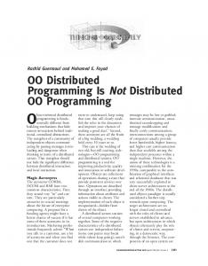
Fig. 1. Event System Overview.
The relationship between event system, event service and event model are summarised from the event system’s perspective in Fig. 1. Apart from depicting how an event system uses an event service that implements a particular event model, Fig. 1 also outlines how event system and service map onto a transport mechanism and how applications use entities as hooks into the event service. Entities are the components of an application that produce and consume events, excluding components of the event service. An entity may play the role of either a producer or a consumer of events, or may act as both a producer and a consumer of events. III. EVENT MODEL DIMENSION The event model defines the application view of an event service. As shown in Fig. 4, we have identified three distinct categories of event model, which are peer to peer, mediator, and implicit. A peer to peer event model allows consuming entities to subscribe at specific named producing entities directly and producing entities to deliver events to specific named subscribed entities directly. The Java distributed event model [26] serves as an example of a peer to peer event model. Event models utilising a mediator allow consuming entities to subscribe at a designated mediator and producing entities to deliver events to the mediator, which then forwards them to the subscribed entities. The mediator sub-hierarchy explores the number and functionality of mediators in the event model. We differentiate between models utilising a single mediator and models exploiting multiple mediators. The CORBA event model1 [27] may use a single mediator, called event channel. Multiple mediators are further divided into functionally equivalent and 1 The CORBA specification allows its event model to utilise a single or multiple mediators. For the purpose of this example, we refer to a CORBA event model utilising a single mediator.
non-functionally equivalent mediators. In the former, all mediators are functionally equivalent. Thus, entities may subscribe or deliver events to any one of them. In SIENA [28], [29], the equivalent to a mediator is called event server. SIENA may utilise a set of different event server topologies. All but the centralised topology exploit multiple, functionally equivalent event servers. When mediators are not functionally equivalent, entities have to subscribe or deliver events to the correct mediator. The CORBA event model2 may utilise multiple event channels each propagating a different type of event. An implicit event model lets consuming entities subscribe to particular event types rather than at another entity or a mediator. Producing entities generate events of some type, which are then delivered to the subscribed entities. The Cambridge event model (CEM) [30] is based on an implicit event model. Generally, the event model defines the manner in which an event service is made visible to the application programmer. It specifies the components of an event service to which the application programmer is explicitly exposed and which are used to subscribe to events and to propagate them. Specifically, the event model classifies the means by which the consuming entities of an application subscribe to the events in which they are interested and the means by which an application raises and delivers events, as well as the number and location of the components involved. In the remainder of this section, we present an example of each of the identified event model categories outlining the manner in which an application programmer uses their respective components. We then conclude the section by discussing the identified categories of event model. The Java distributed event model allows a consumer, called RemoteEventListener, to subscribe to events by invoking a register method on a producer, called EventGenerator. The simplified consumer application below shows how a RemoteEventListener invokes the register method on an explicitly named EventGenerator, passing a reference to itself as a parameter. It is the RemoteEventListener’s responsibility to retrieve the reference to the specific EventGenerator to which it intends to register. The means to retrieve the reference is not specified by the event model. The RemoteEventListener also implements a notify method, the handler that will be invoked by the EventGenerator when delivering a particular instance of an event. TheConsumerApplication {//the RemoteEventListener //subscribe to an explicit producer AnExplicitEventGeneratorRef = retrieveEventGeneratorRef(); AnExplicitEventGeneratorRef.register(this); //handler to deliver an event notify(TheRemoteEventInstance) { processAnEvent(TheRemoteEventInstance); } }
The producer application below shows a simplified version 2 The CORBA specification allows its event model to utilise a single or multiple mediators. For the purpose of this example, we refer to a CORBA event model utilising multiple mediators.
4 of an EventGenerator. The EventGenerator implements the register method through which a RemoteEventListener passes its reference when subscribing. The EventGenerator invokes the notify method on a subscribed RemoteEventListener using the RemoteEventListener’s reference to deliver a particular instance of an event. TheProducerApplication {//the EventGenerator //register a consumer register(RemoteEventListenerRef) { SubscribedRemoteEventListenerRef=RemoteEventListenerRef; } //raising an event AnEventInstance = new Event(someParameters); SubscribedRemoteEventListenerRef.notify(AnEventInstance); } }
Producers, called suppliers, and consumers exploiting the CORBA event model register with the mediator, called event channel, by obtaining interfaces to proxy objects, through which instances of events are exchanged with the channel. In order to do so, both consuming and supplying entities must retrieve the reference to the explicitly named event channel through which they intend to exchange events. Like the Java distributed event model, the CORBA event model does not specify the means to retrieve references to specific event channels. The event channel uses administration objects to maintain the connections to its entities and uses those connections to propagate instances of events. The example below shows a simplified version of an application creating a specific event channel using a library called EventChannelFactory. TheEventChannel = EventChannelFactory.createEventChannel();
The following example outlines a simplified supplier and consumer application. Both are assumed to have retrieved the reference to the specific event channel to which they intend to connect. In a similar fashion, both supplier and consumer application obtain their respective proxy objects in order to connect their supplier and consumer entity to the channel. TheSupplierApplication { //connect a producer to an explicit event channel SupplierAdmin = TheEventChannel.forSuppliers(); ProxyPushConsumer = SupplierAdmin.obtainPushConsumer(); ProxyPushConsumer.connectPushSupplier(TheSupplier); } TheConumerApplication { //connect a consumer to an explicit event channel ConsumerAdmin = TheEventChannel.forConsumers(); ProxyPushSupplier = ConsumerAdmin.obtainPushSupplier(); ProxyPushSupplier.connectPushConsumer(TheConsumer); }
The supplier entity raises events and pushes them to the event channel by invoking the push method on the event channel’s consumer proxy. The event channel then forwards the events to all subscribed consumer entities by invoking the push method on the explicit consumers in turn. Each consumer must implement the push method, the handler that delivers specific instances of events. TheSupplier { //raising an event AnEventInstance = new Event(someParameters); ProxyPushConsumer.push(AnEventInstance); }
TheConsumer { //handler to deliver an event push(TheRemoteEventInstance) { processAnEvent(TheRemoteEventInstance); } }
CEM includes an Interface Definition Language (IDL3) that enables producers to specify (declare) the type of event they can notify and allows consumers to register with the types in which they are interested. A pre-processor is used to translate the IDL code, generating consumer and producer stubs for marshalling and un-marshalling of method invocations. In order to subscribe, a consumer creates an event template representing the event type in which it is interested and then invokes a local register method passing a consumer specific parameter list that includes the template and a handler method to be invoked on event delivery. The example below shows a simplified version of the consumer side of an active badge system. The event type of interest is specified as template, which is then passed to the event service by invoking the register method provided by a local library called EventClient, along with the reference to the handler that delivers events is also passed. TheConsumer { //specify the type of event to which to subscribe template = Badge_Seen(B,S); EventClient.Register(EventHandler, template); //handler to deliver an event EventHandler(TheRemoteEventInstance); processAnEvent(TheRemoteEventInstance); } }
Before generating events, a producer specifies the types of event it produces using IDL declarations. In order to propagate an event of a specific type, a producer instantiates the corresponding event and calls a local signal method to send it to the subscribed consumers. The example below shows a simplified version of the producer side of an active badge system. The producer declares the type of event it produces and raised a specific instance of that event type by invoking the Signal method provided by a local library, called EventServer. Note, invoking the signal method causes the event service to deliver the event to the consumer by invoking its event handler. TheProducer { //specify the type of event that will be produced EventTypeName : INTERFACE = Seen : EVENTCLASS [badge : BadgeId; sensor: SensorId]; END. //raising an event e = Badge_Seen(17, 29); EventServer.Signal(e); }
In summary, an event system exploiting either a peer to peer or a mediator-based event model allows its entities to interact by invoking remote methods directly on each other or on one or more mediators respectively, whereas entities of an event system with an implicit event model interact by subscribing and delivering events locally using event types. Significantly, these approaches differ in the way identifiers
5 to the components exposed to the application programmer are obtained and maintained. Peer to peer and mediator-based event models require the application programmer to obtain identifiers to explicitly named producers and mediators respectively, usually by means of exploiting a lookup table or a naming service, and to maintain them. Every consumer of an event system utilising a peer to peer based event model is required to obtain the identifier of each producer in which it is interested, i.e., the application programmer must ensure a consumer subscribes to the correct set of producers, and to maintain these identifiers during their lifetime. Similarly, entities of an event system utilising a mediator-based event model need to acquire the identifiers of the mediators involved, i.e., the application programmer must track the identifiers to the mediators to which a specific entity needs to connect. However, mediator-based event models are likely to obtain and maintain a smaller number of different identifiers compared to peer to peer based event models. There are likely to be significantly fewer mediators in an event system than producers and their quantity is unlikely to change over time4, certainly compared to the number of producers as they may be created frequently providing services for a limited period of time. Therefore, the number of the components explicitly exposed to the application programmer is expected to be significantly smaller in a mediator-based event model compared to a peer to peer based event model. In contrast, the application programmer in an event system utilising an implicit event model is not required to acquire any identifiers to entities or mediators at all. The application programmer does not need to explicitly identify the producers with which a consumer needs to communicate as consumers subscribe to producers transparently using event types. This requires a more sophisticated event service as it is its responsibility to located peers, to maintain the corresponding identifiers, and to map event types to identifiers. Most significantly, the event model exploited by an event system affects one of the main concepts of event-based communications, namely the anonymity among the entities in the system. The means by which consuming entities subscribe to the events in which they are interested and by which events are propagated and delivered influences the degree of anonymity among them. The peer to peer approach permits specific named entities to interact directly with each other. Consequently, entities are not anonymous to each other. Mediator-based event models, where entities register with one or more mediators, provide a degree of anonymity where entities are anonymous to each other but known to the mediator(s). The implicit approach allows entities to interact transparently exploiting event types. Hence, entities are anonymous to each other but known by the event service that implements the mapping of event types to entities. 3 The IDL of the Cambridge event model is different from the IDL specified by the OMG, but has similar functionality. 4 In the absence of failure, an event system may exploit a single mediator whose reference does not change during the lifetime of the system.
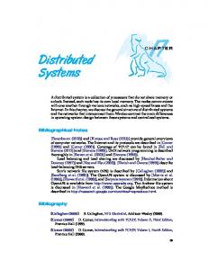
IV. EVENT SERVICE DIMENSION The event service dimension deals with the classification of the properties of an event service. As Fig. 5 shows, we divide the properties of an event service into three distinct categories. The organisation sub tree focuses on the distribution of the entities and the middleware of an event system and on the fashion in which the components that comprise an event service cooperate. The interaction model defines the communication path over which producing and consuming entities communicate with each other. The feature sub hierarchy addresses the other functional and non-functional features proposed by an event service. A. Organisation The organisation sub tree classifies an event service as either centralised or distributed according to the location of the event system’s entities. These two sub categories are further divided exploring the location of the event service middleware. The possible organisation of an event service is summarised in Fig. 6. The entities of an event system can be either centralised or distributed according to their location. The entities of an event system are centralised if they only reside in the same address space on the same physical machine. In contrast, if the entities of an event system are distributed they may be located in different address spaces possibly on different physical machines. Whether the entities of an event system are centralised or distributed, the middleware can be either collocated or separated. Collocated Middleware. The event service is collocated with the entities, it resides only in the same address space(s) on the same physical machine(s). As illustrated in Fig. 7, the organisation of a centralised event service with collocated middleware results in both the entities and the middleware being located exclusively in the same address space. No part of the event system resides outside the implicit single address space. This organisation may be used for small-scale applications consisting of a relatively small number of entities such as graphical user interfaces. For example, the Java AWT delegation event model is implemented by the Java Virtual Machine (JVM) to connect the graphical components of an application sharing their address space with the middleware. Another event service that may be used in a similar fashion is provided by the C# programming language [21]. In contrast, the organisation of a distributed event service with collocated middleware results in the middleware being distributed with the entities, each entity using the part of the middleware that is local to it. Fig. 8 shows the organisation of a distributed event service with collocated middleware, which may include an arbitrary number of address spaces. This organisation has been adopted by CEM and by mSECO [7], an event service implementing the ECO event model [31]. mSECO is implemented as a library that is collocated with each entity. Notably, mSECO is exclusively located in the same address
6 spaces as the entities. However, the address spaces in which the entities reside may or may not be located on different physical machines. Separated Middleware. The event service is at least partially located in one or more separate address spaces possibly on different physical machines. We divide separated middleware into two categories depending on the partitioning of the middleware. Fig. 9 depicts an event service with separated single middleware, whose entities are centralised and whose middleware is located on a single machine. This organisation results in exactly two separate address spaces, one including the entities and the other containing the middleware. Notably, the two address spaces may reside on the same or on two different physical machines. Fig. 10 illustrates an event service with separated single middleware, whose entities are distributed and whose middleware is located on a single machine. This organisation may involve a large number of address spaces and possibly physical machines, depending on the location of the entities’ and the middleware’s address spaces. However, all address spaces may reside on a single physical machine. The CORBA event service utilising a single event channel5 serves as an example of such an organisation. Its entities typically reside in different address spaces distributed over multiple physical machines using an event channel located on another machine. However, the address space in which the event channel resides may be located on the same physical machine as some of the entities’ address spaces. Fig. 11 and Fig. 12 show an event service with separated multiple middleware, whose middleware is distributed over a set of cooperating address spaces possibly on different physical machines, for a centralised and a distributed organisation respectively. Fig. 12 also illustrates that some of the middleware’s address spaces may be located on the same machine as some of the entities. This also applies for centralised entities with separated multiple middleware. We admit the possibility of an organisation of centralised entities with separated multiple middleware although we cannot provide an example for such an organisation. However, SIENA uses an organisation as shown in Fig. 12. SIENA proposes a set of middleware topologies, called server topologies, of which all but the centralised topology use middleware that is distributed over a set of cooperating machines. The organisation adopted by an event service has a major impact on issues related to the scalability of a system, its behaviour in the presence of failed components, and on the mechanism for communication between entities and the middleware. Traditionally, approaches containing centralised middleware components are more likely to experience performance bottlenecks with increasing scale and tend to suffer more in the presence of failures than distributed 5 The CORBA event service may utilise one or more event channels. For the purpose of this example, we refer to a CORBA event service utilising a single event channel.
approaches. The use of middleware located in multiple address spaces allows the distribution of the communication load reducing the risk of performance bottlenecks. Instead of having middleware located in a single address space handling all the communication between the entities in an event system, middleware distributed over multiple address spaces may divide the load. Exploiting middleware distributed over multiple address spaces also avoids potential single points of failure in the system. For example, if the middleware in the organisations illustrated in Fig. 7, Fig. 9, and Fig. 10 fails none of the entities in the corresponding systems will be able to communicate. In contrast, a middleware component failing in one of the organisations depicted in Fig. 8, Fig. 11, and Fig. 12 has a less devastating effect on an event system allowing the entities to communicate even in the presence of failure. Significantly, this depends on the middleware being located in multiple address spaces and not on the distribution of the entities in a system. The organisation of an event service also affects the mechanism through which entities communicate with the middleware. Approaches where entities and middleware reside in different address spaces distributed over different physical machines require a mechanism that supports communication across the boundaries of address spaces and network connections. A much simpler inter-process communication mechanism may be sufficient for organisation where entities and middleware reside in different address spaces on the same physical machine. Entities and middleware sharing an address space may communicate using a programming language specific mechanism such as procedure call and method invocation. B. Interaction Model The interaction sub tree classifies an event service according to the interaction model used by the event system. Generally, the interaction model defines the communication path over which event communication between producing and consuming entities takes place. It defines the number of intermediate middleware components involved and the manner in which intermediates cooperate to route events from producers to consumers. Compared to the organisation model, which focuses on the distribution of the entities and the middleware of an event system describing the static view of an event service, the interaction model describes the information flow in a event system. Hence, it describes the dynamic aspect of an event service. As Fig. 13 depicts, we divide the interaction model into two main categories, namely intermediate and no intermediate, exploring whether and how many intermediate middleware components an event passes through. No Intermediate. The communication path over which event communication between producing and consuming entities takes place does not include intermediate middleware components. Producer and consumer entities communicate with each other through the middleware collocated with each entity. As Fig. 14 illustrates, events that are routed from
7 producers to consumers pass through the respective collocated middleware, but not through any intermediate middleware component. Intermediate. The communication path over which event communication between producing and consuming entities takes place includes at least one intermediate middleware component. Events that are routed from producers to consumers pass through one or more intermediate middleware components. The intermediate interaction model is divided into two sub categories according to the number of intermediate middleware components in the communication path over which event communication between producing and consuming entities takes place. In the centralised intermediate model, the communication path between producing and consuming entities includes a single intermediate middleware component. In contrast, the distributed intermediate involves two or more intermediates through which events are routed from producers to consumers. Fig. 15 depicts the distributed intermediate interaction model outlining a communication path that includes two distributed intermediates. Both centralised and distributed intermediates can be divided further. We classify centralised intermediates according to their number as an event service may exploit a single or multiple centralised intermediates. All communication paths between producing and consuming entities may include the same single centralised intermediate. An event system using this interaction model includes exactly one centralised intermediate. In contrast, an event system may exploit multiple centralised intermediates. Producers and consumers may be divided into groups and all communication paths between the producing and the consuming entities of each group may include a centralised intermediate that is exclusive to the group. This results in an event system using several centralised intermediates, the number of which corresponds to the number of entity groups. The use of multiple centralised intermediates may be motivated by groups of entities, each of which sharing a common interest. The common interest of an individual group may be expressed by a specific type of event that is exclusively handled by a particular centralised intermediate. For example, the CORBA event service may utilise multiple centralised intermediates implemented as event channels. Each channel may handle a specific type of event exclusively. Producing and consuming entities intending to communicate using a specific event type connect to the corresponding event channel, therefore defining the communication path over which event communication takes place. Alternatively, the CORBA event service may utilise a single centralised intermediate implemented as a single event channel through which all events are routed. Fig. 16 and Fig. 17 illustrate the single centralised intermediate and the multiple centralised intermediate interaction model respectively. Fig. 17 shows two groups of entities, each comprising of a producer and a consumer exclusively using a
single centralised intermediate through which events are routed. The communication path associated with one group is outlined as solid arrows and the communication path associated with the other is depicted as dashed arrows. We classify distributed intermediates as partitioned or cooperative according to the fashion in which intermediates cooperate to route events from producing to consuming entities. Generally, the distributed intermediate interaction model includes two or more intermediate middleware components in the communication path between consumers and producers. An event service implementing the partitioned distributed intermediate interaction model consists of one or more independent groups of intermediates, each group handling a specific type of event exclusively. Entities sharing a common interest need to connect to the correct group of intermediates, they need to connect to the group that handles the type of event that corresponds to their common interest. The CORBA event model specification proposes to chain different implementations of event channels, acting as a group of partitioned distributed intermediates, in order to combine nonfunctional features supported by individual event channels. In contrast, cooperative distributed intermediates do not form independent groups; all intermediates cooperate to route events from consumers to producers. Entities connect to the most convenient, i.e., physically closest, intermediate. Each intermediate manages the events of the entities physically connected to it and cooperates with other intermediates to route them to remote entities. Cooperative distributed intermediates cooperate with each other either in a hierarchical or in a non-hierarchical manner. JEDI [32] proposes a hierarchical structure of cooperative distributed intermediates, called dispatching servers. Dispatching servers are interconnected in a tree topology through which events are routed. Entities may connect to any dispatching server, each of them forwards the events it receives from the producing entities connected to it to its parent and to its descendants to route them to all interested consumers. SIENA describes four different topologies of cooperative distributed intermediates. One of them serves as an additional example of hierarchical cooperative distributed intermediates, another two, namely the acyclic and the generic peer to peer topology, illustrate an example of non-hierarchical cooperative distributed intermediates. We sub divide the interaction model that does not include intermediate middleware components into three categories according to the means by which entities address each other. These interaction models are called point to point, named, and implicit. Producer and consumer entities may communicate directly with each other in a point to point fashion, using explicit entity addresses, which are provided by the application. The middleware uses explicit entity addresses and a unicast communication pattern when routing events from producing to consuming entities. The Java distributed event model allows
8 producers to route events to the subscribed consumers using the explicit consumer address provided by the application. Producer and consumer entities may communicate directly with each other using a name service to map event descriptions, such as event types, to entity addresses provided by the application. The middleware uses either a unicast or a multicast communication pattern to route events from a producer to the interested consumers. uSECO [7] uses an name service, called Application Instance Repository (AIR), to resolve the addresses of the entities that are interested in a specific event type and a unicast communication pattern to route events. Producer and consumer entities may communicate directly with each other using an implicit means to map event descriptions to entity addresses provided by the application. The middleware uses a multicast communication pattern when routing events from producers to consumers. mSECO, a multicast version of the uSECO event service, does not rely on an AIR since it uses an implicit means to map events to the multicast addresses representing the interested consumers.
[8]
[9]
[10] [11]
[12] [13] [14]
[15]
C. Features As illustrated in Fig. 18, the feature sub hierarchy addresses the other functional and non-functional features provided by an event service. We omit the discussion of this part of our taxonomy due to the limited space. ACKNOWLEDGMENT The work described in this paper was partly supported by the Irish Higher Education Authority's Programme for Research in Third Level Institutions cycle 0 (1998-2001) and by the Future and Emerging Technologies programme of the Commission of the European Union under research contract IST-2000-26031 (CORTEX - CO-operating Real-time senTient objects: architecture and EXperimental evaluation).
[16]
[17]
[18]
[19]
REFERENCES [1]
[2]
[3]
[4] [5] [6]
[7]
D. Chambers, G. Lyons, and J. Duggan, “Design of Virtual Store using Distributed Object Technology,” in Proceedings of the 5th International Symposium on Software Engineering for Parallel and Distributed Systems (PDSE/ICSE2000). Limerick, Ireland: IEEE Computer Society, 2000, pp. 66-75. M. Addlesee, R. Curwen, S. Hodges, J. Newman, P. Steggles, A. Ward, and A. Hopper, “Implementing a Sentient Computing System,” IEEE Computer, vol. 34, pp. 50-56, 2001. H. Muller and C. Randell, “An Event-Driven Sensor Architecture for Low Power Wearables,” in Proceedings of the Workshop on Software Engineering for Wearable and Pervasive Computing (SEWPC/ICSE2000). Limerick, Ireland: IEEE Computer Society, 2000, pp. 39-41. M. Weiser, “Ubiquitous Computing,” IEEE Hot Topics, vol. 26, pp. 7172, 1993. A. Dearle, “Towards Ubiquitous Environments for Mobile Users,” IEEE Internet Computing, vol. 2, pp. 22-32, 1998. J. Orvalho, L. Figueiredo, and F. Boavida, “Evaluating Light-weight Reliable Multicast Protocol Extensions to the CORBA Event Service,” in Proceedings of the 3rd International Enterprise Distributed Object Computing Conference (EDOC'99). University of Mannheim, Germany, 1999. M. Haahr, R. Meier, P. Nixon, V. Cahill, and E. Jul, “Filtering and Scalability in the ECO Distributed Event Model,” in Proceedings of the
[20] [21] [22]
[23]
[24]
[25] [26] [27]
[28]
5th International Symposium on Software Engineering for Parallel and Distributed Systems (PDSE/ICSE2000). Limerick, Ireland: IEEE Computer Society, 2000, pp. 83-95. G. Banavar, T. Chandra, B. Mukherjee, J. Nagarajarao, R. Strom, and D. Sturman, “An Efficient Multicast Protocol for Content-Based Publish-Subscribe Systems,” in Proceedings of the 19th International Conference on Distributed Computing Systems (ICDCS'99). Austin, TX, USA, 1999. L. Opyrchal, M. Astley, J. Auerbach, G. Banavar, R. Strom, and D. Sturman, “Exploiting IP Multicast in Content-Based Publish-Subscribe Systems,” in Proceedings of IFIP/ACM International Conference on Distributed Processing (Middleware 2000). New York, USA: SpringerVerlag, 2000, pp. 185-207. G. Coulouris, J. Dollimore, and T. Kindberg, Distributed Systems, Concepts and Design, Third ed: Pearson Education Limited, 2001. J. Bacon, K. Moody, J. Bates, R. Hayton, C. Ma, A. McNeil, O. Seidel, and M. Spiteri, “Generic Support for Distributed Applications,” IEEE Computer, vol. 33, pp. 68-76, 2000. M. Erzberger and M. Altherr, “Every Dad Needs a Mom - MessageOriented Middleware,” SoftWired AG, White Paper 1999. S. Maffeis, “Developing Publish/Subscribe Applications with iBus,” SoftWired AG, White Paper 1999. C. Ma and J. Bacon, “COBEA: A CORBA-Based Event Architecture,” in Proceedings of the 4th USENIX Conference on Object-Oriented Technologies and Systems (COOTS). Santa Fe, New Mexico, USA, 1998, pp. 117-131. A. Hopper, A. Harter, and T. Blackie, “The Active Badge System,” in Proceedings of the Conference on Human Factors in Computing Systems (INTERCHI'93). Amsterdam, The Netherlands, 1993. S. J. Kang, S. H. Park, and J. H. Park, “ROOM-BRIDGE: A Vertically Configurable Network Architecture and Real-Time Middleware for Interoperability between Ubiquitous Consumer Devices in Home,” in Proceedings of the IFIP/ACM International Conference on Distributed Systems Platforms (Middleware2001). Heidelberg, Germany: SpringerVerlag, 2001, pp. 232-251. T. Harrison, D. Levine, and D. Schmidt, “The Design and Performance of a Real-Time CORBA Event Service,” in Proceedings of the 1997 Conference on Object- Oriented Programming Systems, Languages and Applications (OOPSLA). Atlanta, Georgia, USA: ACM Press, 1997, pp. 184-200. J. Bacon, K. Moody, and W. Yao, “Access Control and Trust in the use of Widely Distributed Services,” in Proceedings of the IFIP/ACM International Conference on Distributed Systems Platforms (Middleware2001). Heidelberg, Germany: Springer-Verlag, 2001, pp. 295-310. K. O'Connell, V. Cahill, A. Condon, S. McGerty, G. Starovic, and B. Tangney, “The VOID Shell: A Toolkit for The Development of Distributed Video Games and Virtual Worlds,” in Proceedings of the Workshop on Simulation and Interaction in Virtual Environments. University of Iowa, Iowa City, USA, 1995, pp. 172-177. Sun Microsystems Inc., Java AWT: Delegation Event Model: Sun Microsystems Inc., 1997. Microsoft Corporation, C# Language Specification, Version 0.28: Microsoft Corporation, 2001. B. Martin, C. Pedersen, and J. Bedford-Roberts, “An Object-Based Taxonomy for Distributed Computing Systems,” IEEE Computer, vol. 24, pp. 17-27, 1991. Object Management Group, CORBAservices: Common Object Services Specification - Notification Service Specification, Version 1.0: Object Management Group, 2000. Object Management Group, The Common Object Request Broker: Architecture and Specification, Revision 2.2: Object Management Group, 1995. Iona Technologies, “Orbix 3 Product Family,” Iona Technologies, White Paper April 1999. Sun Microsystems Inc., Java Distributed Event Specification: Sun Microsystems Inc., 1998. Object Management Group, CORBAservices: Common Object Services Specification - Event Service Specification: Object Management Group, 1995. A. Carzaniga, “Architectures for an Event Notification Service Scalable to Wide-area Networks,” : Politecnico di Milano, Italy, 1998.
9 [29] A. Carzaniga, D. Rosenblum, and A. Wolf, “Design of a Scalable Event Notification Service: Interface and Architecture,” Dept. of Computer Science, University of Colorado, USA, Technical Report CU-CS-86398, August 1998. [30] J. Bacon, J. Bates, R. Hayton, and K. Moody, “Using Events to Build Distributed Applications,” in Proceedings of the Second International Workshop on Services in Distributed and Networked Environments (SDNE'95). Whistler, British Columbia, Canada, 1995, pp. 148-155. [31] G. Starovic, V. Cahill, and B. Tangney, “An Event Based Object Model for Distributed Programming,” in Proceedings of the International Conference on Object Oriented Information System. London, UK: Springer-Verlag, 1995, pp. 72-86. [32] G. Cugola, E. Di Nitto, and A. Fuggetta, “Exploiting an Event-Based Infrastructure to Develop Complex Distributed Systems,” in Proceedings of the 20th International Conference on Software Engineering (ICSE'98). Kyoto, Japan, 1998.
10
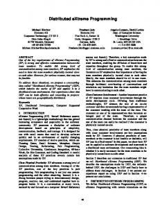
APPENDIX The figures that allow a taxonomy user to easily trace paths through the hierarchy to discover relevant properties are depicted in this section. As summarised in Fig. 2, the figures consist of nodes, one of which is the root node and some of which are leaves. Nodes are connected by directed paths. The directed paths are represented by a set of arrows describing the nature of the paths leaving a specific node. A set of dashed arrows leaving a specific node indicates that exactly one path has to be chosen when tracing through that node. Solid arrows indicate that at least one path has to be chosen, whereas double lined arrows indicate that all possible paths need to be selected. In order to apply the taxonomy to an event system, starting from the root node, a taxonomy user traces paths through the hierarchy selecting the connections that most accurately describe the event system until each selected path reaches a leave. The terms associated with the nodes along a path describe a property of the event system.
Event System
Event Model
Event Service
Fig. 3. Taxonomy Root Dimension.
Event Model
Peer to Peer
Implicit
Mediator
Single
Multiple
1 Node
Select all
Leave
Select at least one
Functionally Equivalent
Non Functionally Equivalent
Select exactly one
Fig. 4. Event Model Dimension. Fig. 2. Taxonomy Legend.
For example, Fig. 18 shows that the features of an event service include both functional and non-functional features by using double lined arrows to describe the paths between the nodes. Hence, when tracing trough the features node all paths, i.e., both of them, must be selected to describe the corresponding properties of the event system. Fig. 4 depicts that an event model can be characterised as either peer to peer, mediator or implicit. The dashed arrows connecting the nodes, which imply that exactly one path has to be chosen, illustrate this.
Event Service
Organisation
Interaction Model
Fig. 5. Event Service Dimension.
Organisation
Centralised
Collocated Middleware
Separated Middleware
Single
Multiple
Fig. 6. Event Service Organisation.
Distributed
Collocated Middleware
Separated Middleware
Single
Multiple
Features
11
Machine
Addr. Space
P
P
P
Producer Entity
C
Consumer Entity
M M C
Machine
Addr. Space
P
Machine
Legend:
Address Space Address Space P
Machine
Middleware
Addr. Space
Addr. Space
C
C
Communication
Machine
Machine
Addr. Space
Addr. Space
P
C
M
M
Machine
Addr. Space
C
Fig. 7. Centralised Event Service with Collocated Middleware.
M
Machine
Fig. 10. Distributed Event Service with Separated Single Middleware.
Machine Addr. Space Address Space M
Machine Addr. Space Address P Space C
Machine
Machine
Addr. Space
Addr. Space
P
C
M
M
Machine
C
P
Addr. Space Address Space M
Fig. 8. Distributed Event Service with Collocated Middleware.
Fig. 11. Centralised Event Service with Separated Multiple Middleware.
Machine
Machine
Addr. Space
Addr. Space
Addr. Space
P
M
P
Machine Address Space Address Space P
Address Space Address Space
Machine Machine
C M P
Addr. Space C
Addr. Space M
Machine Addr. Space C
C
Fig. 9. Centralised Event Service with Separated Single Middleware.
Fig. 12. Distributed Event Service with Separated Multiple Middleware.
12
Application
Application
P
C
Event Service
Event Service
Application
Application
P
C
Event Service
Event Service
Event Service
Transport Mechanism
Transport Mechanism
Fig. 16. Single Centralised Intermediate.
Fig. 14. No Intermediate.
Application
Application
P
C
Event Service
Event Service
Event Service
Application Application P P
Application Application C C
Event Service Event Service
Event Service Event Service
Event Service
Event Service
Event Service
Transport Mechanism
Transport Mechanism
Fig. 17. Multiple Centralised Intermediate.
Fig. 15. Distributed Intermediate.
Interaction Model
Intermediate
Centralised Intermediate
Single
No Intermediate
Distributed Intermediate
Multiple
Point to Point
Cooperative
Hierarchical
Named
Implicit
Partitioned
Non Hierarchical
Fig. 13. Event Service Interaction Model.
Features
Functional
Event Propagation Model
Event Type
Event Filter
Fig. 18. Event Service Features.
Non Functional
Mobility
Composite Events
QoS
Ordering
Fault Tolerance