122
IEEE TRANSACTIONS ON EDUCATION, VOL. 49, NO. 1, FEBRUARY 2006
Teaching DSP Software Development: From Design to Fixed-Point Implementations Woon-Seng Gan, Senior Member, IEEE, and Sen M. Kuo, Senior Member, IEEE
Abstract—In this paper, a digital signal processing (DSP) software development process is described. It starts from the conceptual algorithm design and computer simulation using MATLAB, Simulink, or floating-point C programs. The finite-word-length analysis using MATLAB fixed-point functions or Simulink follows with fixed-point blockset. After verification of the algorithm, a fixed-point C program is developed for a specific fixed-point DSP processor. Software efficiency can be further improved by using mixed C-and-assembly programs, intrinsic functions, and optimized assembly routines in DSP libraries. This integrated software-development process enables students and engineers to understand and appreciate the important differences between floating-point simulations and fixed-point implementation considerations and applications. Index Terms—Digital signal processing (DSP) software development, floating-point and fixed-point C programming, real-time digital signal processing.
I. INTRODUCTION
D
IGITAL signal processing is pervasive in many modern technologies from multimedia and digital communications to consumer electronics, such as digital cameras, digital video disk (DVD) players, and Moving Picture Experts Group Layer-3 Audio (MP3) players. DSP enables the user to enhance signals, increase communication rate, and store more data. Industry requires engineers to have both design and programming skills for DSP applications. For these reasons, teaching and learning DSP is becoming an important component in a college education, especially teaching DSP-based systems with programmable fixed-point DSP processors that are used for real-world applications. An integrated approach in teaching the concepts of DSP, design and development of DSP systems, and programming in C or assembly on fixed-point DSP processors is beneficial and insightful to the understanding of real-time DSP issues. This integrated approach in teaching real-time DSP is seldom employed because of lack of time and resources. However, with the advancement of integrated software development tools, teaching this integrated DSP software development from design to implementation can be done very effectively. A detailed introduction of design tools, finite-word-length analysis and simulation, effective process to develop fixed-point DSP programs, and a complete list of useful hands-on examples and exercises are available in the latest real-time DSP textbooks Manuscript received March 16, 2004; revised September 12, 2005. W.-S. Gan is with the School of Electrical and Electronic Engineering, Nanyang Technological University, Singapore 639798 (e-mail:
[email protected]). Sen M. Kuo is with the Department of Electrical Engineering, Northern Illinois University, DeKalb, IL 60115 USA. Digital Object Identifier 10.1109/TE.2005.863425
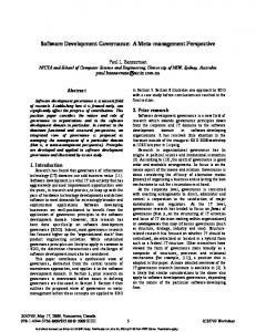
Fig. 1.
Flowchart of DSP software development process.
[1], [2]. There are many DSP educational activities that emphasize DSP applications, include real-time applications [3], CD-ROM-based demonstration and multimedia computer software [4], [5], rapid development of DSP code on floating-point DSP processors [6], teaching of real-time DSP programming using the fixed-point processors [1] [2], [7], [18]–[20] and floating-point processors [8]–[10]. In this paper, a complete DSP software development process that utilizes MATLAB, Simulink, and the Code Composer Studio (CCS) for the TMS320C5000 processors [11]–[17] is introduced. Algorithm design and verification by floating-point simulations is first carried out. The finite-word-length effects of the fixed-point implementation are also analyzed. Different levels of fixed-point programming, such as fixed-point C, fixed-point C with intrinsics, fixed-point C with assembly routines, and fixed-point C using optimized routines from DSP libraries are benchmarked. Finite-impulse-response (FIR) filtering is used as an example to describe the software development process from the algorithm design and floating-point simulation to the fixed-point implementation using CCS. The overall flowchart of DSP software development is illustrated in Fig. 1. The rest of the paper is organized as follows. Section II introduces the concepts of floating-point DSP design and simulation. Section III presents the concepts of fixed-point programming and methods needed to overcome finite-word-length problems. Section IV demonstrates a step-by-step approach in implementing an FIR filter on a fixed-point DSP and shows how to conduct this process in a one-semester DSP design course.
0018-9359/$20.00 © 2006 IEEE
GAN AND KUO: TEACHING DSP SOFTWARE DEVELOPMENT: FROM DESIGN TO FIXED-POINT IMPLEMENTATIONS
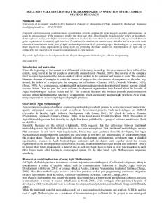
Fig. 2.
123
Filter Design and Analysis Tool (FDATool).
In addition, several problem sets and applications are presented for students to explore the design, simulation, and programming techniques. II. ALGORITHM DESIGN AND FLOATING-POINT SIMULATION An important step in DSP applications is to develop working algorithms. This step includes algorithm design and an in-depth study of the numerical properties for different inputs, conditions, and parameters. Floating-point simulations to evaluate the developed algorithms can be carried out using MATLAB functions or Simulink models. Results obtained from MATLAB/Simulink simulations are used as the reference for benchmarking the subsequent C code developments. The Signal Processing Toolbox provides two graphic user interface (GUI) tools: the Signal Processing Tool (SPTool) [11] and Filter Design and Analysis Tool (FDATool) [12]. SPTool performs general DSP functions, such as filter design, filtering, spectral analysis, input capture, system characteristics analysis, and simulation in different floating- and fixed-point formats. This tool will be discussed in Section IV-A. The FDATool shown in Fig. 2 performs advanced filter design, transformation, realization, and coefficient quantization. This GUI tool allows students to design a filter using double-precision, floating-point format; quantize the designed filter with given word length and formats; and analyze its quantization effects. Another useful feature is that the FDATool can export the designed filter coefficients to a C header file for a C implementation. This feature is shown in Fig. 3, which provides the option to specify the data type as double-precision (64-bit) or single-precision (32-bit) floating-point numbers or 8-, 16-, and 32-bit signed/unsigned integers. Floating-point C programs specify data types as float (32-bit single precision) or double (64-bit double precision). Details
on C programming are examined in a later section using FIR filtering as an example. Visual C++ running on a personal computer (PC) is used as the platform to develop and test the floating-point C programs. Results from the C programs are saved in data files for comparison with respective results obtained by MATLAB or Simulink. Floating-point programs avoid arithmetic overflow, saturation, truncation/rounding, and dynamic range problems. However, the drawbacks are increased memory requirements and a slower execution speed. This drawback is not serious in implementing DSP algorithms on a PC with a main objective of verifying the algorithms’ functionalities. The introduction of floating-point C programs provides an important link to fixed-point programs that can be executed on DSP processors. Floating-point C statements can easily be translated to fixed-point C programs. In this way, the transition from PC to DSP platforms becomes easier since most students are familiar with C programming on a PC. III. FIXED-POINT SIMULATION AND PROGRAMMING Fixed-point simulations using Simulink can be conducted by replacing floating-point block set with the respective fixed-point equivalent from the fixed-point block set, which allows the user to mimic the DSP processor’s arithmetic. For example, the blocks are configured to work on the 16-bit fixed-point (Q.15) format, which is commonly used in most 16-bit fixed-point DSP processors, such as the TMS320C5000 [13], [14]. Q.15 to using format represents numbers in the range of a sign bit and 15 fractional bits with 2’s complement format. In some instances, mixed- formats are required in different modules in the same algorithm, and the fixed-point block set can test the arithmetic correctness of this mixed- algorithm. A FixPt GUI block identifies overflow problems, data types,
124
IEEE TRANSACTIONS ON EDUCATION, VOL. 49, NO. 1, FEBRUARY 2006
Fig. 3. Window for exporting filter’s coefficients to C-header file.
and scaling used at each block in the system. Fig. 4(a) shows an example of performing multiplication and addition using Q.15 arithmetic, and Fig. 4(b) shows the fixed-point settings and the statistics of the fixed-point arithmetic. Signal range is reported, and the scaling factors of each block can be fine tuned. If the fixed-point blockset is not available, an M-file can be written to recast the floating-point variables into Q.15 numbers, as shown in the following MATLAB instruction:
Note that the floating-point number must be scaled within and before conversion. The Q.15 format eliminates multiplicative overflow since multiplying two Q.15 numbers results in a number bounded within the same range, with the ex. A major challenge for fixed-point impleception of mentation is to solve the overflow problem in fixed-point arithmetic. Scaling of the input signals and shifting of the respective intermediate and final results are critical to the implementation of DSP algorithms on fixed-point processors. Scaling has to be done explicitly by the programmer, which is generally a tedious and error-prone process. In some applications, the worst-case constraint on scaling can be partially lifted based on prior knowledge of the signal’s dynamic range. This reduced scaling preserves more bits, thus improving the signal-to-quantization-noise ratio. Scaling technique, such as using - and -norm [1], can be used in FIR and infinite-impulse-response (IIR) filtering. However, it may be difficult to implement in time-varying cases, such as adaptive filtering. In addition to scaling, saturation arithmetic and guard bits can be applied to prevent overflow. Saturation mode limits the arithmetic results to the most positive or most negative number, thus maintaining the polarity of the original signal. In Q.15 arithmetic, exceeding positive and negative numbers are clipped to and , respectively. Guard bits in the DSP processors’ accumulators allow a sequence of additions without overflow. The saturation mode of the accumulator must be switched
off before using the guard bits, which allows the carry bit into the guard bits. C language is a valuable programming tool for computationally intensive tasks. One can often more easily write a program in C so that the algorithm can be tested offline using the simulated (or digitized) data. The efficiency of a C compiler has been improved significantly in recent years, but C programs may never completely replace hand-optimized assembly programs for DSP processors. Therefore, most manufacturers of DSP processors provide assembly-optimized, C-callable functions in DSP libraries to increase the efficiency of C code. Because the majority of code is written in C, the software can be ported to other processors easier than code that is completely written in assembly language. As DSP processors became faster and more complicated, the justification of using full assembly programming decreased. A fixed-point C program that can be run on a PC is suggested. This program allows programmers to evaluate the fixedpoint arithmetic and confirm its numerical properties. Fixedpoint programming requires careful shifting of signals to prevent overflows, while maintaining the numerical accuracy at the same time. Comparison of the fixed-point C results with the results obtained from MATLAB (or floating-point C) can assure that the quantization error is within an acceptable level. An important notation is that no fixed-point data type exists in traditional C compilers on a PC; instead, the integer type is used to represent the fixed-point data in Q.15 format. Therefore, fixedpoint data must be converted to integer, thus making number interpretation more difficult. An example is given in Section IV on the conversion of data from floating- to fixed-point format. The fixed-point C program is then modified from the PC platform to the CCS environment. Several methods are introduced for handling signal and coefficient quantization, arithmetic shifting, manipulating bit precision, rounding/truncation, using guard bits of the accumulator, and scaling of results to prevent overflow. The overflow control mechanism of fixed-point C programming must be explicitly handled by the programmer.
GAN AND KUO: TEACHING DSP SOFTWARE DEVELOPMENT: FROM DESIGN TO FIXED-POINT IMPLEMENTATIONS
125
Fig. 4. Fixed-point simulation of multiplying and adding two sine waves. (a) Fixed-point block set. (b) GUI window that displays the statistics of the arithmetic.
For example, a routine must be written to track the overflow condition (sign changes when adding two numbers with same sign), and proper scaling (shifting of data to reduce its values) must be carried out during the arithmetic operations. Low-level programming methods (such as using intrinsics and assembly
code) are often preferred since they provide programmers with the knowledge of the overflow flag and ability to set the saturation mode in the code. Section IV-C will explain how these methods can be applied to prevent overflow. Numerical properties and quantization errors against the MATLAB reference
126
IEEE TRANSACTIONS ON EDUCATION, VOL. 49, NO. 1, FEBRUARY 2006
are also carried out. In addition, one must shift left 1 bit of the product to remove the extra sign bit introduced by binary multiplications. This operation must be performed explicitly for every multiplication in C programs using different fixed-point formats. The primary goal of software development is to write code that is easy to develop, debug, understand, maintain, and port on different processors. In addition, a program that requires less memory and makes the most efficient use of the unique computational resources of a given processor is desired. These two goals are sometimes contradictory. A high-level C language is easier to write for the given algorithm and to port from one processor to another. It follows the underlying algorithm directly, thus making understanding and maintenance easy. The handcrafted assembly code by the experienced programmer is generally smaller and faster, but it takes longer to develop. Intrinsic functions can be used in the fixed-point C programs for a specific DSP processor. These intrinsics included in the C5000 C compilers can be called as C functions. They produce a set of optimized assembly-language instructions to execute low-level operations, such as multiply two 16-bit integers to form a 16-bit result. However, these intrinsics have fixed shifting, rounding, and settings; thus, the user has no flexibility in adjusting their operations. In general, execution bottlenecks usually occur in the loops (especially inner loops) of a program. These loops may occupy only 20% of the code but may take 80% of the time to execute. The best strategy is to code the entire algorithm in C first; identify the time-critical bottlenecks; and then rewrite only that small section of code in assembly language. Because C compilers of DSP processors generate assembly code for further optimization by the programmer, time-critical sections of code can be identified by using the profiler and optimized by replacing it with the handcrafted assembly code. Another effective method is to use the hand-optimized functions coded in assembly language by engineers or in the libraries provided by the manufacturers. These assembly routines may be called as C functions or inline coded into the C program. Because of the continuous improvement in C-compiler efficiency and the availability of user-friendly integrated software development tools, a mix of C-and-assembly program is the most effective way of developing software for DSP systems. The initial, steep, learning-curve associate with assembly language programming can be relaxed with the introduction of mixed C-and-assembly programming. Only a subset of instructions (such as store, load, multiply, and add) is required for introducing the general concept of writing assembly programs. In addition, understanding the DSP architecture is important for learning assembly programming. This knowledge guides the students in implementing assembly code with efficient usage of addressing modes, registers, memory, peripherals, etc., thus increasing the execution speed. These low-level processor, control operations performed only by the assembly-language code are crucial to some real-time implementations. IV. CASE STUDY OF DSP SOFTWARE DEVELOPMENT The time schedule to conduct a one-semester (16-week) DSP design course is listed in Table I. The objective of this course
TABLE I TIME SCHEDULE FOR CONDUCTING A REAL-TIME DSP DESIGN CLASS
is for students to understand and apply the design flow of the DSP software development. Emphasis is placed on the fixedpoint implementation issues. Students who take this class may not have the knowledge of theoretical digital signal processing; thus, some DSP fundamentals and related issues are introduced in the class. Some topics can be modified to suit different needs with different emphases. For example, adaptive FIR filters can be used for solving some important applications, such as adaptive channel equalization and echo cancellation. The examples of implementing these modules are described in the following sections. A. DSP Fundamentals and Floating-Point Simulations Some DSP fundamentals, such as how digital filters attenuate noise using MATLAB or Simulink, are first introduced. Simulink models are used to illustrate the usage of filters in real-world applications, such as attenuating power-line hum in electrocardiogram signals or enhancing the bass of musical signals using a graphic equalizer. In addition, Simulink spectral display blocks are used to demonstrate the effects of filtering in frequency domain and highlight the important filter specifications and parameters. These introductory demonstrations inspire students’ thinking of how digital filters can be used in their daily life and encourage further studies on their implementation. Necessary signal processing topics, such as -transform and frequency analysis, are also introduced to allow students to understand the theory of digital filtering without using rigorous
GAN AND KUO: TEACHING DSP SOFTWARE DEVELOPMENT: FROM DESIGN TO FIXED-POINT IMPLEMENTATIONS
TABLE II FLOATING-POINT C PROGRAM FOR IMPLEMENTATION FILTERING ON A PC
127
OF
FIR
Fig. 5. Signal Processing Tool (SPTool).
mathematics. An important issue of the filter design is the filter specifications, such as passband and stopband ripples, passband and stopband cutoff frequencies, order of filter, and the conversion between linear and decibel scales. In addition, the conversion of frequencies in hertz, normalized unit, and radian must be clearly understood before moving to the practical filter design. MATLAB provides many useful functions and GUI tools (SPTool and FDATool) for students to design and implement digital filters for the given specifications. As shown in Fig. 5, the SPTool imports different input signals to its environment, and applies the designed filter to produce the filtered output. Important filter characteristics include magnitude and phase responses, group delay, impulse response, step response, and pole/zero plot, which can be examined using this GUI tool. B. Floating-Point C Programming FIR filtering can be implemented in a floating-point C program, listed in Table II, where the filter coefficients, input, and output signals are all represented in 32-bit floating-point format. The filter coefficients are converted from the double-precision into single-precision floating-point format using the quantization option available in the FDATool. The quantized FIR filter is also tested for possible overflow by summing all the absolute value of the filter’s coefficients. If the summation is less than one, no overflow will occur in the fixed-point implementation. Subsequently, these coefficients are exported to a C-header file, coeff_c_sp.h, which also declares coefficient array B[i] and filter length BL. The input data file, in.dat, is opened and read by the filter sample by sample, and the output signal is written to the data file, out.dat, in the same fashion. This output file can be compared with the output obtained by MATLAB in order to evaluate the difference between double-precision and singleprecision floating-point formants. C. Fixed-Point C Programming Before embarking on fixed-point C programs, students have to understand the numerical issues in programming for
fixed-point processors. Several commonly used techniques [2] to prevent overflow in fixed-point implementations, which include methods of scaling, saturation mode, and guard bits, are introduced. The fixed-point C program can be simplified by using software simulation tools, such as the FDATool. The FDATool is a useful teaching tool for demonstrating quantization effects using different precisions. This tool allows users to quantize filter coefficients, input, output, multiplicands, products, and sums for specific word-length and data formats. These quantization parameters can be set individually in terms of the number mode, round mode, overflow mode, and format. For example, students can examine differences in filter coefficients and frequency responses by using Q.15 format versus the 64-bit double-precision reference. This powerful feature facilitates the evaluation of finite-word-length effects caused by fixed-point implementation of digital filters. Therefore, any potential overflow problems in the algorithm can be detected and corrected by simulation. This fixed-point simulation helps to eliminate the needs of C code to check for overflow. At this stage, the introduction of DSP architectures and programming techniques are crucial. The special DSP architecture topics include multiply–add computational (MAC) unit, arithmetic and logic unit (ALU), Harvard and pipelining architectures, and addressing modes that include special addressing techniques to perform circular buffering and nonoverhead looping. In addition, programming techniques for fractional
128
IEEE TRANSACTIONS ON EDUCATION, VOL. 49, NO. 1, FEBRUARY 2006
TABLE III PARTIAL LISTING OF THE FIXED-POINT FIR FILTERING
Digital filtering routines available in the DSP libraries (DSPLIB) for the TMS320C5000 are listed in [13] and [14]. In this experiment, a C program that calls the FIR-filtering routine fir in the C5000 DSPLIB is used. The function fir.asm is written in optimized C5000 assembly code. This function can be called in C as follows:
multiplication and addition, scaling, and overflow prevention in C and assembly programs are also discussed. The floating-point C program introduced in the previous section can serve as a blueprint for developing a fixed-point C program. As discussed in Section III, floating-point coefficients must be converted to a 16-bit integer, using the Q.15 conversion formula, which multiplies a floating-point number by 32768 and then rounds the result to an integer. In addition, the input signal samples are normalized and rounded to 16-bit integers and saved in the file in_int.dat. These operations can be done using the following MATLAB commands:
The argument x is the pointer to the input-signal vector of nx elements; h is the pointer to the coefficient vector of size nh; r is the output-signal vector of nx elements; dbuffer is the signal (or delay) buffer that must be initialized before running this function; and oflag is the overflow flag. The oflag allows the programmer to take action in handling an overflow problem. For example, a programmer can saturate the output to its maximum . or minimum value when The final fixed-point implementation of FIR filtering uses a 100% hand-optimized assembly program. Only the required instructions and addressing modes are explained. The assembly programming allows the instructor to relate the coding to the DSP processor’s architecture (such as using the accumulator, accessing memory, addressing registers) and the important features (such as pipelining, hardware looping, and addressing modes). CCS supports the benchmarking of cycle counts for the FIR filter implemented in a fixed-point C program, C program with intrinsics, C program calling optimized assembly DSP library functions, and hand-optimized assembly program. In addition, students are also asked to observe the memory usage of the above programs and determine the tradeoffs for each programming method.
% The multiply–add operations of FIR filtering are realized in fixed-point C using a long integer (32 bits). The output (16-bit integer) is computed by scaling the accumulated value (32-bit) with a variable scale (32768) for using Q.15 format. The partial listing of the fixed-point C program is given in Table III. A complete listing of the code is found in [1]. The fixed-point C program for the C5000 processors can be modified from the above fixed-point C program by recasting the variables to integer (16-bit), performing the data type conversion, and shifting the multiply–add results. The FDATool can export designed filter coefficients directly to the CCS as shown in Fig. 6. This feature converts the filter coefficients to signed 16-bit integers and saves them in a C-header file that can be included in the C program. A partial program is listed in Table IV, and a complete listing can be found in [1]. The multiplication results must be shifted right by 15 bits and save the least significant 16 bits to remove the redundant sign bit generated by fractional multiplication. Rounding of the final result can also be carried out by adding 32768 to the final 32-bit result before truncating to 16 bits. The performance of a fixed-point C program can be further improved by using intrinsics that are available for the C5000 processors. However, the disadvantage of using processor-specific intrinsics is the lack of flexibility in porting software to different DSP processors. In this experiment, the multiplication (_lsmpy) and addition (_lsadd) intrinsics are used to implement the MAC operations for the FIR filtering. The kernel code of the C program using these two intrinsics is listed in Table V. These intrinsics ease the C programming by performing the necessary left-shifting of one bit and provide the saturated 32-bit result. In this way, the programmer will not need to be concerned with the overflow problem.
D. Additional Design Problems The experience learned from the design and implementation of FIR filters can be extended by students to explore more in-depth issues for practical DSP applications. These additional exercises are conducted in an exploratory manner, with little intervention from the instructor. Students use the acquired skills of algorithm design, simulation, and programming to explore new topics and solve the associated problems. Students are given two weeks to complete these design problems at their own pace. Continual assessment is also being carried out by the instructor to evaluate the students’ ability to understand and solve the design problems. Some additional design problems are listed below. 1) Sample Processing Versus Block Processing: The preceding FIR filtering is carried out in a sample-by-sample manner, that is, processing the data when a new sample is received. An alternate mode is to capture a block of samples, process the whole block of data, and acquire a new block of data at the same time. In this way, the overhead of setting up direct-memory access (DMA) and input–output interrupts incurred in the sample-by-sample processing is greatly minimized. The block processing has the advantage of achieving higher throughput compared with the sample-by-sample approach. However, the disadvantages are processing delay,
GAN AND KUO: TEACHING DSP SOFTWARE DEVELOPMENT: FROM DESIGN TO FIXED-POINT IMPLEMENTATIONS
Fig. 6.
129
Export filter coefficients (in Q.15) as a C-header file for the CCS.
TABLE IV PARTIAL LISTING OF THE FIXED-POINT C PROGRAM FOR THE CCS
3) IIR Filtering: IIR filters are often used to replace FIR filters to design lower order filters that satisfy a given specification. A high-order IIR filter is first designed, and the polynomial factorization is used to factor the filter into several second-order sections (and one first-order section if the filter is odd order). Usually, the poles of the second-order filters are grouped with the nearest pair of zeros to form a biquad (second-order IIR filter), and these biquads are arranged in either a gain-increasing or a gain-decreasing manner. The gain-increasing grouping (with the highest gain at the output) is often used to prevent excessive amplification at the earlier stages of filtering. E. FIR Filter-Based Applications
TABLE V USING INTRINSICS FOR MULTIPLICATION AND ADDITION
increased memory requirement for implementing multiple buffers, and more complicated programming to switch between different data buffers. 2) Symmetric FIR Filters: A symmetric FIR filter with coefficients that are either even- or odd-symmetric guarantees that the filter has linear phase. The symmetric FIR filter is often stated in textbooks as a structure that can reduce 50% multiplication and memory requirements. However, in actual DSP implementation, the computational saving may not be achieved in low-order filters because of the architecture of processor and memory configuration.
The final section (last three weeks) of the course asks students to design and implement fixed-point DSP applications. Many important applications related to digital filtering are suggested and highlighted in the textbook [1]. Some examples are as follows: 1) low-pass filters used in sample-rate conversion; 2) analysis and synthesis filters used for signal compression; 3) parallel filter bank employed in equalizers for enhancing the perception of the music signals; 4) parallel filter bank commonly used in audio coding for analyzing the signals; 5) a pair of filters (commonly known as the head-related transfer functions) used to filter a monosound source so that it is being perceived as coming from a specific position; 6) filters used to synthesize the transfer function of a room or concert hall for special sound effects; 7) narrow-band notch filters used to remove power-line hum; 8) adaptive filters deployed in applications, such as active noise control, channel equalization, adaptive predictor, echo cancellation.
130
Fig. 7.
IEEE TRANSACTIONS ON EDUCATION, VOL. 49, NO. 1, FEBRUARY 2006
Results of the end-of-semester survey for program outcomes achieved by this class.
Students can choose one of the above applications as their miniproject, or propose their own projects, within the scope of this class. The wide ranges of DSP applications provide useful examples for students to embark in the final hands-on project that combine all their previous experience in DSP algorithm design, simulation, analysis, and programming to produce a workable application. They can even port the working code onto a DSP Starter Kit (DSK) [15], [16] for real-time processing. The DSK hardware (connects to the PC) contains the DSP processor, analog–digital converter, digital–analog converter, external memories, and other supporting peripherals. This hardware enables students to plug in real-world analog signals and listen to the processed signals using loudspeakers or observe the signals using an external scope or spectrum analyzer. V. OUTCOME ASSESSMENT To prepare the students for the educational objectives to be achieved, a set of program outcomes (which describes what students are expected to know and are able to do by the time of graduation) has been adopted for this class. This course has adopted nine (out of 11) of the Accreditation Board for Engineering and Technology (ABET) learning outcomes for assessment. These nine ABET outcomes are briefly listed as follows: a) ability to apply knowledge of mathematics, science, and engineering; b) ability to design and conduct experiments, as well as to analyze and interpret data; c) ability to design a system, component, or process to meet desired needs; d) ability to function on multidisciplinary teams; e) ability to identify, formulate, and solve engineering problems; f) ability to communicate effectively; g) recognition of the need for, and an ability to engage in, lifelong learning; h) knowledge of contemporary issues; i) ability to use the techniques, skills, and modern engineering tools necessary for engineering practice. Multiple measures, both direct and indirect, are employed to evaluate the effectiveness of the department in meeting its goals.
To judge the course’s success at helping students develop those nine outcomes, students in the class are surveyed at the end of semester, and the results are summarized in Fig. 7 to reflect what the students reported learning. For each outcome, students have to choose from the following categories; a numeric value from 5 to 1 shown inside the parenthesis is assigned accordingly: Strongly Agree (5), Agree (4), Neither Agree Nor Disagree (3), Disagree (2), or Strongly Agree (1). The average of values for each outcome is used to derive the chart given in Fig. 7, which shows how all nine outcomes are achieved. In particular, high assessment result of outcomes k) on the students’ ability to use the techniques, skills, and modern engineering tools necessary for engineering practice was obtained. This outcome strongly supports the course objective of teaching students to understand and apply the design flow of the DSP software development. From the indirect teaching assessment over the past few semesters, more than 90% of the students are able to understand the concepts of fixed-point signal processing design and able to program fixed-point signal processing code. Almost 80% of the students have successfully completed their FIR filter-based project. Some students (about 20%) even ported their code successfully to the DSK hardware. Overall, the learning objectives stated in Section IV of this paper have been met, and the step-by-step approach in guiding the students from design to fixed-point implementation has been well received by the students. VI. CONCLUSION This paper has presented a methodology that progressively supports DSP design from floating-point simulations to fixed-point implementations. To illustrate effectively fixed-point DSP applications, MATLAB and Simulink are used for design, analysis, and implementation of DSP algorithms. This fixed-point simulation is a crucial step in writing an efficient and numerically stable fixed-point C code. CCS for the TMS320C5000 processors is used for laboratory experiments, projects, and applications. These useful tools illustrate the concepts of real-time DSP and bridge the gap between theoretical signal processing and real-time applications. To utilize advanced DSP architecture for software development
GAN AND KUO: TEACHING DSP SOFTWARE DEVELOPMENT: FROM DESIGN TO FIXED-POINT IMPLEMENTATIONS
and maintenance, the mixing of C-and-assembly programs is emphasized. This paper also presents a two-level approach for conducting hands-on exercises. Necessary software tools must first be introduced and follow step-by-step guidelines on designing, simulating, verifying, and developing programs. More exercises and problems follow to reinforce the understanding of these topics. This approach emphasizes the “see” and “do” of digital signal processing, which makes the learning of this subject fun and enjoyable. This class contributes to nine ABET outcomes, and assessment results show those outcomes are achieved. REFERENCES [1] S. M. Kuo and W. S. Gan, Digital Signal Processors. Upper Saddle River, NJ: Prentice-Hall, 2005. [2] S. M. Kuo and B. H. Lee, Real-Time Digital Signal Processing. New York: Wiley, 2001. [3] S. M. Kuo and G. D. Miller, “An innovative course emphasizing realtime digital signal processing applications,” IEEE Trans. Educ., vol. 39, no. 2, pp. 109–113, May 1996. [4] J. B. Schodorf, M. Yoder, J. H. McClellan, and R. W. Schafer, “Using multimedia to teach the theory of digital multimedia signals,” IEEE Trans. Educ., vol. 39, no. 3, pp. 336–341, Aug. 1996. [5] A. Spanias and E. W. Painter, “A software tool for introducing speech coding fundamentals in a DSP course,” IEEE Trans. Educ., vol. 39, no. 2, pp. 143–152, May 1996. [6] W. S. Gan et al., “Rapid prototyping system for teaching real-time digital signal processing,” IEEE Trans. Educ., vol. 43, no. 1, pp. 19–24, Feb. 2000. [7] W. S. Gan, “Teaching and learning the hows and whys of real-time digital signal processing,” IEEE Trans. Educ., vol. 45, no. 4, pp. 336–343, Nov. 2002. [8] I. M. Abdel-Qader, B. J. Bazuin, H. S. Mousavinezhad, and J. K. Patrick, “Real-Time digital signal processing in the undergraduate curriculum,” IEEE Trans. Educ., vol. 46, no. 1, pp. 95–101, Feb. 2003. [9] N. Kehtarnavaz and M. Keramat, DSP System Design Using the TMS320C6000. Upper Saddle River, NJ: Prentice-Hall, 2001. [10] R. Chassaing, DSP Applications Using C and the TMS320C6x DSK. New York: Wiley, 2002. [11] Signal Processing Toolbox User’s Guide, The MathWorks, Inc., Natick, MA, 2002. Version 6. [12] Filter Design Toolbox User’s Guide, The MathWorks, Inc., Natick, MA, 2002. Version 2. [13] TMS320C54x DSP Library Programmer’s Reference, Texas Instruments, Dallas, TX, 2001. SPRU422b. [14] TMS320C55x DSP Library Programmer’s Reference, Texas Instruments, Dallas, TX, 2002. SPRU422F.
131
[15] 5402 DSK One-Day Workshop: Student Guide, Texas Instruments, Dallas, TX, May 2000. [16] 5510 DSK One-Day Workshop: Student Guide, Texas Instruments, Dallas, TX, May 2000. [17] TMS320C54x Code Composer Studio: Tutorial, Texas Instruments, Dallas, TX, Feb. 2000. [18] R. Chassaing and D. W. Horning, Digital Signal Processing with the TMS320C25. New York: Wiley, 1990. [19] Digital Signal Processing Applications Using the ADSP-2100 Family, A. Mar, Ed., Analog Devices, Inc., Norwood, MA, 1992. [20] M. El-Sharkawy, Digital Signal Processing Applications with Motorola’s DSP56002 Processor. Englewood Cliffs, NJ: Prentice-Hall, 1996.
Woon-Seng Gan (S’89–M’90–SM’00) received the B.Eng. (first-class hons.) and Ph.D. degrees, both in electrical and electronic engineering, from the University of Strathclyde, U.K., in 1989 and 1993, respectively. In 1993, he joined the School of Electrical and Electronic Engineering, Nanyang Technological University (NTU), Singapore, as a Lecturer and became Senior Lecturer in 1998. Currently, he is an Associate Professor at NTU. He teaches several undergraduate, postgraduate, and industry courses on digital signal processing and real-time signal processing implementation. He has published more than 120 technical papers in peer-reviewed journals and international conferences, and he recently coauthored a book titled Digital Signal Processors: Architectures, Implementations, and Applications (Englewood Cliffs, NJ: Prentice-Hall, 2005). His research interests include adaptive signal processing, psycho-acoustical signal processing, and real-time digital signal processing. Dr. Gan is a Member of the Audio Engineering Society. He is a Professional Engineer of Singapore.
Sen M. Kuo (SM’00) received the B.S. degree from National Taiwan Normal University, Taipei, Taiwan, R.O.C., in 1976 and the M.S. and Ph.D. degrees from the University of New Mexico, Albuquerque, in 1983 and 1985, respectively. In 1993, he was with Texas Instruments, Houston, TX. He is currently a Professor and Chair in the Department of Electrical Engineering, Northern Illinois University, DeKalb. He is the leading author of three books: Active Noise Control Systems (New York: Wiley, 1996), Real-Time Digital Signal Processing (New York: Wiley, 2001), and Digital Signal Processors (Englewood Cliffs, NJ: Prentice-Hall, 2005). He served as a consultant to several companies on developments of real-time digital signal processing (DSP) applications. He holds seven U.S. patents and has published over 150 technical papers. His research focuses on active noise and vibration control, real-time DSP applications, adaptive echo and noise cancellation, digital audio applications, and digital communications. Prof. Kuo received the IEEE first-place transactions (Consumer Electronics) paper award in 1993 and the Faculty-Of-Year Award in 2001 for accomplishments in research and in the scholarly area.