The series SR and SRM safety cable pull switching devices developed and
manufactured by BERNSTEIN AG are designed and approved in accordance
with ...
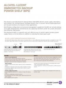
Safety Cable Pull Switches SRM, SR
SRM
SR
General information on safety cable pull switches The series SR and SRM safety cable pull switching devices developed and manufactured by BERNSTEIN AG are designed and approved in accordance with the standards IEC 947-5-5, DIN EN 60947-5-5 and ISO 13850, i.e. on actuation or in the event of cable breakage, the emergency stop switching device locks automatically and can only be reset to its initial setting by means of the resetting device on the switch. In order for the overall system to conform to the standards EN 60947-5-5 and EN 13850 governing the emergency stop function of cable pull switches it is necessary to integrate a spring in the system. The reasoning behind this requirement is that a person who triggers the emergency stop functions does not need to consider the activation direction. With the spring it is possible to pull the cable in the direction of the cable pull switch, thus activating the emergency stop function.
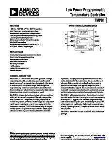
The maximum possible span length of a pull cable switch is always dependent on the temperature fluctuations to which the system is exposed. It is possible that the pull cable switch may trip due to the fact that, owing to its temperature coefficient, the length of the steel cable can change in response to changes in temperature. Ultimately, this change in length is dependent on the length of the cable, the difference in the temperature change and the type of springs used in the pull cable switch. Overview 1 shows which cable lengths are possible as a function of change in temperature. Pull cable counterspringr With overstretch safeguard based on compression spring principle
Safety cable pull switches may only be used in control power circuits. Safety cable pull switches are used on accessible sides of conveyor systems or machines. In contrast to Emergency Stop switching devices (e.g. mushroom pushbuttons) installed at intervals, with which the emergency stop signal can only be generated at the device itself, with the safety cable pull switch it is possible to generate the signal at any point in a section. Depending on the type of switching device, a span of up to 75 m can be achieved with a pull cable connected to the pulling element.
L0 min.
L0 max.
Application
112
Type
SR...100/SR...175/SRM...175 SR...300/SRM... 300
Spring Art. No.
3911042153
3911042154
L0 min. Lmax.
383 487
483 653
Advantages of SRM/SR safety cable pull switches:
l The SR (plastic enclosure) and SRM (metal enclosure) safety cable pull switches are available with the Quickfix quick-connect system, which renders unnecessary cable eye stiffeners, cable grips and turnbuckles that are other wise required for mounting the cable. Added to this, the time required to install the cable is drastically reduced. Ver sions with a conventional eye are, of course, also available.
cable pull switch is imminent. This electronic output signals in good time that maintenance/adjustment is required otherwise the machine will shut down. This output can also be used for event signalling purposes or optionally available indicator lamps can be connected. This connection configuration con forms to "preventative maintenance" requirements.
l During installation/adjustment of the cable span, the correct tension of the cable can be checked through the integrated inspection window. To ensure optimum cable tension as part of the adjustment procedure, the tips of the indicator arrows should be aligned with the marking.
l All variants of the SRM and especially of the SR are equipped with an integrated emergency stop impact button that can be actuated by pressing in hazardous situations. In the same way as pulling the pull cable, the safety contacts are opened and the switch is locked.
l A second inspection window integrated in the SRM version makes it possible to check the status of the locking function and of the contacts. Yellow in the inspection window indicates that the safety cable pull switch is locked. Green in the inspec tion window indicates that the cable pull switch is ready for operation and the cable assembly is monitored.
l The type SRM...E-... safety cable pull switches are optionally available with a remote indicator for monitoring the cable tension. This option has an integrated sensor unit that mo- nitors situations in which the cable tension may overshoot or undershoot the permissible value or triggering of the safety
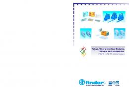
Overview 1 Span L max. in metres [m] 1
Max. temperature variation in Kelvin (K)
2
3
4
5
6
7
8
9 10 11 12 13 14 15 16 17 18 19 20 22 24 26 28 30 32 34 36 38 40 42 44 46 48 50 55 60 65 70 75
+/- 40 K +/- 35 K +/- 30 K +/- 25 K +/- 20 K +/- 15 K +/- 10 K +/- 5 K +/- 3.5 K
SR...100 SR...175/ SRM...175
Max. span 25 metres Max. span 37.5 metres
SR...300 / SRM...300
Max. span 75 metres
The parameter 100, 175 and 300 in the product designation indicates the force of the springs used in the cable pull switch. It should be noted that a grater actuating force is required for higher spring forces.
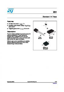
Installation example Rope length Lg = 200 mm
2-5m
La = 150 mm
113
Safety Cable Pull Switches
Max. span length
37,5 metres (Dimensioned drawing 2)
2 Ö/2 S
3 Ö/1 S
2 Ö/2 S
3 Ö/1 S
Quickfix (Dimensioned drawing 1)
6012929087 SRM-U1Z/U1Z-QF-300
6012999096 SRM-A2Z/U1Z-QF-300
6012929085 SRM-U1Z/U1Z-QF-175
6012999094 SRM-A2Z/U1Z-QF-175
Öse (Dimensioned drawing 2)
6012921091 SRM-U1Z/U1Z-LU-300
6012991100 SRM-A2Z/U1Z-LU-300
6012921089 SRM-U1Z/U1Z-LU-175
6012991098 SRM-A2Z/U1Z-LU-175
Quickfix with remote monitoring (Dimensioned drawing 1)
6012929088 SRM-U1Z/U1Z-QF-300-E
6012999097 SRM-A2Z/U1Z-QF-300-E
6012929086 SRM-U1Z/U1Z-QF-175-E
6012999095 SRM-A2Z/U1Z-QF-175-E
Eye with remote monitoring (Dimensioned drawing 2)
6012921092 SRM-U1Z/U1Z-LU-300-E
6012991101 SRM-A2Z/U1Z-LU-300-E
6012921090 SRM-U1Z/U1Z-LU-175-E
6012991099 SRM-A2Z/U1Z-LU-175-E
Approvals
114
75 metres (Dimensioned drawing 1)
Technical data Electrical data Rated insulation voltage Rated operating voltage Conventional thermal current Utilization category Short-circuit protection Protection class
Ui max. Ue max. Ithe Ue /Ie
250 V AC 240 V 10 A AC-15, Ue /Ie 240 V / 3 A; 120 V/6 A DC-13 Ue /Ie 250 V/0.27 A; 125 V/0.55 A 6 A gL/gG I
Mechanical data Enclosure Ambient temperature Mechanical service life Switching frequency max. Mounting B10d Type of connection Conductor cross sections Cable entry Protection class
Aluminium pressure die-casting -30°C to +80°C 1 x 10⁵ ≤ 20 / min. 4 x M6 or 4 x M5 0.2 mill. Screw connections Single-wire 0.5 - 1.5 mm2 3 x M20 x 1.5 IP67 conforming to IEC/EN 60529
Standards VDE 0660 T100, DIN EN 60947-1, IEC 60947-1 VDE 0660 T200, DIN EN 60947-5-1, IEC 60947-5-1 VDE 0660 T210, DIN EN 60947-5-5, IEC 60947-5-5 ISO 13850
Contact type
1 Ö/1 S (Zb)
2 Ö (Zb)
Action contacts
U1Z
A2Z
Circuit symbol
Slow-action contacts
Slow-action contacts
Schaltdiagramm On OFF Rastung / Latch / Verrouillage
Rastung / Latch / Verrouillage
Rastung / Latch / Verrouillage
Rastung / Latch / Verrouillage
The pulling force data depend on the type of switch used. (SRM...175/SRM...300) Tolerances: Switching point +/- 0.5 mm, actuating force +/- 15 %
115
Safety Cable Pull Switches
Max. span length
75 metres (Dimensioned drawing 1)
2 Ö/2 S
4Ö
2 Ö/2 S
4Ö
Quickfix (Dimensioned drawing 1)
6011629028 SR-U2Z-QF 300
6011691051 SR-A4Z-QF 300
6011629024 SR-U2Z-QF 175
6011691050 SR-A4Z-QF 175
Quickfix N.A. (Dimensioned drawing 2)
6011629019 SR-U2Z-NA-QF 300
6011691054 SR-A4Z-NA-QF 300
6011629027 SR-U2Z-NA-QF 175
6011691053 SR-A4Z-NA-QF 175
Öse (Dimensioned drawing 3)
6011620020 SR-U2Z 300
6011691048 SR-A4Z 300
6011621026 SR-U2Z 175
6011691047 SR-A4Z 175
Approvals
Technical data Electrical data Rated insulation voltage Rated operating voltage Conventional thermal current Utilization category Short-circuit protection Protection class
Ui max. Ue max. Ithe Ue /Ie
250 V AC 240 V 10 A AC-15, Ue /Ie 240 V / 3 A 6 A gL/gG II, Insulated
Mechanical data Enclosure Ambient temperature Mechanical service life Switching frequency max. Mounting B10d Type of connection Conductor cross sections Cable entry Protection class Standards VDE 0660 T100, DIN EN 60947-1, IEC 60947-1 VDE 0660 T200, DIN EN 60947-5-1, IEC 60947-5-1 VDE 0660 T210, DIN EN 60947-5-5, IEC 60947-5-5 ISO 13850 116
37.5 metres (Dimensioned drawing 2)
PA 6 GV (UL94-V0) -25°C to +70°C as per EN 60947-5-5 ≤ 20 / min. 4 x M5 0.02 mill. Cage clamp terminal ≤ 1.5 - 2 mm2 3 x M20 x 1.5 IP67 conforming to IEC/EN 60529
25 metres (Dimensioned drawing 3)
2 Ö/2 S
4Ö
6011629032 SR-U2Z-QF 100
6011691049 SR-A4Z-QF 100
6011629031 SR-U2Z-NA-QF 100
6011691052 SR-A4Z-NA-QF 100
6011621030 SR-U2Z 100
6011691033 SR-A4Z 100
Contact type
2 Ö/2 S (Zb)
4Ö
Action contacts
U2Z
A4Z
Circuit symbol
Slow-action contacts
Slow-action contacts
Schaltdiagramm On Off Latch
Latch
Latch
Latch
The pulling force data depend on the type of switch used. (SR...100/SR...175/SR...300) Tolerances: Switching point +/- 0.5 mm, actuating force +/- 15 %
117