Sep 20, 2016 - and express the labeling problem as a set of time intervals ... core component of professional geographic information systems. ... We further provided optimal integer linear programming approaches and ... systems, we adapt the models to make them more broadly ..... The orange dashed line illustrates the.
Temporal Map Labeling: A New Unified Framework with Experiments Lukas Barth∗
Benjamin Niedermann∗
Martin N¨ollenburg†
Darren Strash∗
arXiv:1609.06327v1 [cs.CG] 20 Sep 2016
Abstract The increased availability of interactive maps on the Internet and on personal mobile devices has created new challenges in computational cartography and, in particular, for label placement in maps. Operations like rotation, zoom, and translation dynamically change the map over time and make a consistent adaptation of the map labeling necessary. In this paper, we consider map labeling for the case that a map undergoes a sequence of operations over a specified time span. We unify and generalize several preceding models for dynamic map labeling into one versatile and flexible model. In contrast to previous research, we completely abstract from the particular operations (e.g., zoom, rotation, etc.) and express the labeling problem as a set of time intervals representing the labels’ presences, activities, and conflicts. The model’s strength is manifested in its simplicity and broad range of applications. In particular, it supports label selection both for map features with fixed position as well as for moving entities (e.g., for tracking vehicles in logistics or air traffic control). Through extensive experiments on OpenStreetMap data, we evaluate our model using algorithms of varying complexity as a case study for navigation systems. Our experiments show that even simple (and thus, fast) algorithms achieve near-optimal solutions in our model with respect to an intuitive objective function.
1
Introduction
Dynamic digital maps are becoming more and more ubiquitous, especially with the rising numbers of location-based services and smartphone users worldwide. Consumer applications that include personalized and interactive map views range from classic navigation systems to mapbased search engines and social networking services. Likewise, interactive digital maps are a core component of professional geographic information systems. All these map services have in common that the content of the map view is changing over time based on interaction with the system (i.e., zooming, panning, rotating, content filtering, etc.) or the physical movement of the user or a set of tracked entities. A key ingredient of every (paper or digital) map are features like geographic places, points of interest, or search results that all need to be labeled by a name or a graphical symbol in order to become meaningful for the map user. While we focus on point features in our experiments, our results can be generalized to other map features, such as line or area features. For static maps, labeling—the selection and placement of labels—is a well-studied research area in cartography and computational geometry. One of the primary quality constraints for labeling, is that no two labels may overlap each other [5, 11]. Most formalizations of the static map labeling problem are NP-hard and, therefore, a variety of approximation algorithms and heuristics have been proposed in the literature. See [13] for an overview. More recently, dynamic map labeling has captured the interest of researchers, leading to the study of labeling problems in maps that support certain subsets of operations like zooming, ∗ †
Karlsruhe Institute of Technology, Karlsruhe, Germany Algorithms and Complexity Group, TU Wien, Vienna, Austria
1
panning, and rotations. The main difficulty in dynamic maps is that the selection and placement of labels must be temporally coherent (or consistent) during all map animations resulting from interactions, rather than being optimized individually for each map view as in static map labeling. A map with temporally coherent labeling avoids visually distracting effects like jumping or flickering labels [1]. Again, consistent dynamic map labeling problems are typically NP-hard and approximation results as well as heuristics are known [1, 2, 8, 9, 14]. However, most of the existing algorithmic results in dynamic map labeling take a global view on the map, which optimizes over the whole interaction space, regardless of which portion of that space is actually explored by the user. In this paper we take a more local view on dynamic map labeling. Our aim is to develop algorithms that optimize the labeling for a specific map animation given offline as an input. Any feature or label that is not relevant for that particular animation—for example, because it never enters the map view—can be ignored by our algorithms. This approach not only allows us to compute better labelings by removing unnecessary dependencies and non-local effects, but it also reduces the problem size, since fewer features and labels must be taken into account. We first formulate an abstract, generic framework for offline, temporal labeling problems, in which labels and potential conflicts between labels are represented as intervals over time. To represent label’s presence, we use a presence interval, which corresponds to the time that a label is present (but not necessarily displayed) in the map view. That is, whenever a label enters the map view, a corresponding presence interval starts, and whenever a label leaves the view, its current presence interval ends. Next, a conflict interval (or simply conflict) between two present labels starts and ends at the points in time at which the two labels start and stop intersecting. A temporal labeling is then simply represented as a set of subintervals—the labels’ activity intervals, during which the labels are displayed, where no two conflicting labels are displayed simultaneously. Depending on the objective and consistency constraints of the labeling model, different sets of subintervals may be chosen by the algorithm. This is a very versatile framework, which includes, for instance, map labeling for car navigation systems, in which the map view changes position, angle, and scale according to the car’s position, heading, and speed following a particular route. To give another, seemingly different example, it also includes the problem of labeling a set of moving entities in a map view (e.g., for tracking vehicles in logistics or planes in air traffic control). Also non-map related applications such as labeling 3D scenes as they occur in medical information systems are covered by our model. Put differently, the model comprises any application in which start and end times of label presences and conflicts can be determined in advance. Further, the conflicts are not restricted to label-label conflicts but may also include label-object conflicts. Our Results In a companion paper [6] we investigated the underlying models from a theoretical point of view, showing NP-hardness and W[1]-hardness for optimization problems in these models. We further provided optimal integer linear programming approaches and approximation algorithms, but without any experimental results. In this paper, we build upon our previous work, present more sophisticated heuristic algorithms, and provide an extensive experimental evaluation of our proposed temporal labeling models and algorithms in a case study for navigation systems. Our experiments illustrate the usefulness of our models for this application, and further show the strength of each algorithm under each model. Ultimately, our experiments show that that simple but fast algorithms achieve near-optimal solutions for the optimization problems—which is very encouraging, given the hardness results. Lastly, while the models in [6] were developed specifically for navigation systems, we adapt the models to make them more broadly applicable to temporal map labeling scenarios.
2
1.1
Related Work
We now systematically review prior research on label placement in maps focusing on dynamic map labeling. In 2003, Petzold et al. [20] presented a framework for automatically placing labels on dynamic maps. They split the label placement procedure into two phases, namely a (possibly timeconsuming) pre-processing phase and a query phase which computes the labeling of customscale maps. However, this approach does not guarantee that labels do not jump or flicker while transforming the map. In 2006, Been et al. [1] introduced the first formal model for dynamic maps and dynamic labels, formulating a general optimization problem. They described the change of a map by the operations zooming, panning, and rotation. In order to avoid flickering and jumping labels while transforming the map with zooming and panning, they required four desiderata for consistent dynamic map labeling. These comprise monotonicity, that labels should not vanish when zooming in or appear when zooming out (or any of the two when panning), invariant point placement, where label positions and size remain invariant during movement, and history independence—placement and selection of labels should be a function of the current map state only. Monotonicity was modeled as selecting for each label at most one scale interval, the so-called active range, during which the label is displayed. They introduced the active range optimization problem (ARO) maximizing the sum of active ranges over all labels such that no two labels overlap and all desiderata are fulfilled. They proved that ARO is NP-hard for star-shaped labels and presented an optimal greedy algorithm for a simplified variant. That model was the point of departure for several subsequent papers considering the operations zooming, panning and rotation, mostly independently. Been et al. [2] took a closer look at different variants of ARO for zooming. They showed NP-hardness and gave approximation algorithms. In the same manner further variants were investigated by Liao et al. [14]. Gemsa et al. [7] presented a fully polynomial-time approximation scheme (FPTAS) for a special case of ARO, where the given map is one-dimensional and only zooming is allowed. However, they combined the selection problem with a placement problem in a slider model. Zhang et al. [24] also considered the model of Been et al. [1] for zooming, however, instead of maximizing the total sum of active ranges, they maximized the minimum active range among all labels. They discussed similar variants as Liao et al. [14] and Been et al. [2], also proving NP-hardness and giving approximation algorithms. Gemsa et al. [8, 9] extended the ARO model to rotation operations. They first showed that the ARO problem is NP-hard in that setting and introduced an efficient polynomialtime-approximation scheme (EPTAS) for unit-height rectangles [8]. In a second step they experimentally evaluated heuristics, algorithms with approximation guarantees, and optimal approaches based on integer linear programming [9]. A similar setting for rotating maps was considered by Yokosuka and Imai [23]. Instead of ARO, they aimed at finding the maximum font size for which all labels can always be displayed without overlapping. Apart from the results based on the consistency model of Been et al. [1], other approaches have been considered, too. Maass et al. [16] described a view management system for interactive three-dimensional maps of cities also considering label placement. Mote [18] presented a fast label placement strategy without a pre-processing phase. Luboschik [15] described a fast particle-based strategy that locally optimizes the label placement. All these approaches have in common that they do not take the consistency criteria for dynamic map labeling into account. A different generalization of static point labeling is dynamic point labeling. In this case not the map is being transformed, but the point set changes by adding or removing points as well as by moving points continuously. Inspired by air-traffic control, De Berg and Gerrits [4] considered moving points on a static map that all must be labeled. They presented a sophisticated heuristic for finding a reasonable trade-off between label speed and label overlap. Finally, Buchin and Gerrits [3] showed that dynamic point labeling is strongly PSPACE-complete. 3
(a)
(b)
Translation Rotation
Restaurant
Zoom
Gas Station Museum Wildlife Park
Figure 1: Model. (a) Overall view of the scene. Depending on the rotation, translation, and zoom, the camera shoots a restricted part of the scene. The objects to be labeled are represented by black dots. (b) The corresponding viewport of the camera. The labels are placed near their objects.
2
Model
We now formally describe the temporal labeling model that we use in the remainder of the paper. It unifies and generalizes the models presented by Been et al. [1], De Berg and Gerrits [4] as well as the model that we introduced in [6]. The notation is mainly adopted from [6].
2.1
Basic Model
We are given a set O = {o1 , . . . , on } of objects in a scene over a given time span T = [0, T ]. Further, for each object o we are given a label `, e.g., text describing o. We denote the set of labels by L = {`1 , . . . , `n }, where `i is the label of oi . To quantify the importance of a label, we define for each label ` ∈ L a positive weight w` ∈ R+ . We have a restricted view on the scene through a camera, i.e., the objects are projected onto an infinite plane P such that we can only see a restricted section V of P , where V models the viewport of the camera; see Fig. 1 for an example. During the time interval T , the objects are moving and the camera changes its perspective by changing its position, direction and zoom. We denote the plane P and the viewport V at time t by P (t) and V (t), respectively. Depending on the position of the object oi ∈ O, each label `i has a certain shape and position on P (t) at time t; we denote the geometric shape of ` at time t by `(t). Following typical map labeling models we may assume that `(t) is a (closed) rectangle enclosing the text; one may also assume other shapes. In the following we introduce some further notations to describe the setting precisely. According to the perspective and position of the camera, not every label `(t) is contained in the viewport at time t. We say that a label ` is present at time t if `(t) is (partly) contained in V (t); that is, `(t) ∩ V (t) 6= ∅. We assume that the time intervals, during which a label ` is present, are given by a set Ψ` of disjoint, closed sub-intervals of T ; see Fig. 2 and Fig. 3. For such an interval [a, b] ∈ Ψ` we also write [a, b]` indicating that it belongs to `. We denote the union of all those sets Ψ` by Ψ and assume that Ψ is a multi-set, as it may contain the same interval [a, b] multiple times, where each occurrence of [a, b] belongs to a different label. Two labels ` and `0 are in conflict at time t ∈ T , if the geometric shapes of both labels intersect, i.e., `(t) ∩ `0 (t) 6= ∅. Following [6] we describe the occurrences of conflicts between two labels `, `0 ∈ L by a set of closed intervals: C`,`0 = {[a, b] ⊆ T | [a, b] is maximal and ` and `0 are in conflict at all t ∈ [a, b]}. For such an interval [a, b] ∈ C`,`0 we also write [a, b]`,`0 indicating that it is a conflict interval between ` and `0 . We denote the set of all conflict intervals over all pairs of labels by the multi-set C. To avoid overlaps between labels, we display a label ` only at certain times when no other displayed label overlaps `; the label ` is said to be active at those times. We describe the activity of `, by a set Φ` of disjoint intervals1 . For such an interval [a, b] ∈ Φ` we also write [a, b]` to 1
Technically, one needs to distinguish between open and closed intervals, i.e., for closed rectangular labels, the presence and conflict intervals are closed but the activity intervals are open. However, including or excluding the interval boundaries makes no difference in our algorithms and hence we decided to simply use the notation
4
(a)
N
`
N
`
`0
(b)
`0
N
N
`
` `0
`0
`
`0
` `0 Present
Conflict
Active
Present
Conflict
Active
Figure 2: Label activity. The maps rotate clockwise, while the labels keep aligned horizontally. Black labels are active, while gray labels are inactive. The intervals illustrate presence, conflict and activity intervals. The witness label `0 justifies (a) the start (b) the end of `’s activity interval.
indicate that the activity interval belongs to `. The union of all activity intervals over all labels is denoted by the multi-set Φ. We say that two activity intervals [a, b]` and [c, d]`0 of two labels ` and `0 are in conflict if there is a time t in the intersection of the open intervals (a, b) ∩ (c, d) such that the labels ` and `0 are in conflict at t. An instance of temporal labeling is then defined by the set L of labels, the set Ψ of presence intervals and the set C of conflict intervals. We thus completely abstract away the geometry of the problem, while all essential information of the temporal labeling instance is captured combinatorially in Ψ and C. In this paper, we primarily focus on conflict-free label selection, and therefore assume that Ψ and C are given as input. However, in Section 3 we describe how to construct Ψ and C for the specific application of navigation systems. Similarly to Been et al. [1] for a temporal labeling we require the following temporal consistency criteria: (C1) A label should not be set active and inactive repeatedly to avoid flickering. (C2) The position and size of a label should be changed continuously, it should not jump. (C3) Labels should not overlap. We formalize those consistency criteria and say the the activity set Φ is valid (see Fig. 3) if (R1) for each activity interval I` ∈ Φ there is a presence interval I`0 ∈ Ψ with I` ⊆ I`0 , (R2) for each presence interval I` ∈ Ψ there is at most one activity interval I`0 ∈ Φ with I`0 ⊆ I` , and (R3) no two activity intervals of Φ are in conflict. Requirement (R1) enforces that a label is only displayed if it is present in the viewport. Requirement (R2) prevents a label from flickering during a presence interval (C1), while (R3) enforces that no two displayed labels overlap (C3). In fact, (R2) is only a minimum requirement for avoiding flickering labels, which we later extend to stronger variants. By assuming that labels’ positions are fixed relative to their anchors, labels may not jump (C2) as long as labeled objects are either fixed or move continuously. From now on we assume that an activity set is valid, unless we state otherwise.
2.2
Optimization Problem
Based on the introduced model we investigate two optimization problems for temporal labeling that aim to maximize the overall active time of labels. The first problem allows for any number of labels to be active at the same time, and the second allows at most k labels to be active at the same time, which reduces the amount of presented information. We define the weight of an activity interval [a, b]` ∈ Φ to be w([a, b]` ) = (b − a) · w` . Problem 1 (GeneralMaxTotal). Given: Instance (L, Ψ, C). P Find: Activity set Φ maximizing [a,b]` ∈Φ w([a, b]` ). [a, b] for all respective intervals unless stated otherwise.
5
(a)
Valid Activity
(b)
`3
`3
`2
`2
`1
`1
T
Present
(c)
Conflict
T
Active
Present
(d)
AM2
`3
`3
`2
`2
`1
`1
T
Present
Conflict
T
Active
Present
AM1
Conflict
Active
AM3
Conflict
Active
Figure 3: Valid activities and the activity models AM1, AM2 and AM3. Figure 9a shows an example of a single frame of a temporal labeling that is optimal with respect to GeneralMaxTotal. While such a labeling is acceptable for general applications such as spatial data exploration, for small-screen devices, such as car navigation systems, the same labeling may overwhelm or distract the user with too much additional information. In fact, psychological studies have shown that untrained users are strongly limited in receiving, processing, and remembering information (e.g., see [17]). For applications that do not receive a user’s full attention it is therefore desirable to restrict the number of simultaneously displayed labels, which we formalize as an alternative optimization problem as follows. Problem 2 (k-RestrictedMaxTotal). Given: Instance (L, Ψ, C), k ∈ N. P Find: Activity set Φ maximizing [a,b]` ∈Φ w([a, b]` ), s.t. at any time t at most k labels are active. In [6] we showed that GeneralMaxTotal is NP-hard and W[1]-hard. By W[1]-hardness, we cannot expect algorithms for k-RestrictedMaxTotal that are fixed-parameter tractable on k. This even applies for the example of navigation systems that we consider in Sect. 3.1. We therefore focus on heuristics for the two problems.
2.3
Activity Models
So far labels may become active or inactive within the viewport without any external influence, see, e.g., the second activity interval of `3 in Fig. 3(a). Hence, the activity behavior of labels, even in an optimal solution Φ, is not necessarily explainable to a user by simple and direct observations such as “the label becomes inactive at time t, because at that moment an overlap starts with another active label”. The absence of those simple logical explanations may lead to unnecessary irritations of the user. To account for that we introduce the concept of justified activity intervals. Consider a label ` with activity interval [a, b]` ∈ Φ. We say that the start of [a, b]` is justified if ` enters the viewport at time a or if there is a witness label `0 such that a conflict of ` and `0 ends at a and `0 is active at a; see Fig. 2(a). Analogously, we say that the end of [a, b]` is justified if ` leaves the viewport at time b or if there is a witness label `0 such that a conflict of ` and `0 begins at b and `0 is active at b; see Fig. 2(b). If both the start and end of [a, b]` are justified, then [a, b]` is justified. Following our preceding paper [6], we distinguish the three activity models AM1, AM2, and AM3 that consider justified activity intervals; see Fig. 3. While for AM1, a label may only become active and inactive when it enters and leaves the viewport, for AM2 it may also become 6
(b)
(a)
Zoom
LVL 3 LVL 2 LVL 1
Time
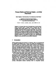
Figure 4: Trajectory. (a) The corners of the selected route (black polyline) are smoothed by circular arcs obtaining a continuous and differentiable trajectory (orange curve). (b) The black rectilinear curve shows the zoom levels assigned to the underlying roads over time. The orange dashed line illustrates the interpolated actual zooming of the viewport.
inactive before leaving the viewport if a witness label justifies this event. AM3 further allows a label to become active after entering the viewport if a witness label justifies that event. AM1. An activity Φ satisfies AM1 if any activity interval [a, b]` ∈ Φ is justified and there is a presence interval [c, d]` ∈ Ψ of the same label ` with [a, b]` = [c, d]` . AM2. An activity Φ satisfies AM2 if any activity interval [a, b]` ∈ Φ is justified and there is a presence interval [c, d]` ∈ Ψ of the same label ` with a = c. AM3. An activity Φ satisfies AM3 if any activity interval [a, b]` ∈ Φ is justified. We have described only the core of the model. Depending on the application it can be easily extended to more complex variants, e.g., requiring minimum activity times.
3
Workflow
In this section we describe a simple but flexible workflow for temporal labeling problems. This workflow consists of two phases. In the first phase a concrete geometric labeling problem is transformed into an abstract temporal labeling instance I = (L, Ψ, C). This step critically depends on the concrete geometric model of the given temporal labeling problem. Here, we consider the application of a car navigation system; other labeling problems, such as labeling moving entities, can be handled similarly. In the second phase, either GeneralMaxTotal or k-RestrictedMaxTotal is solved for the output instance I from the first phase. We now describe these two phases in greater detail.
3.1
Phase 1 – Transformation into Intervals
This phase depends on the specific labeling problem given. It transforms the input for a particular geometric setting into a temporal labeling instance that can then be handled independently from the geometry. Example: Navigation Systems For our experiments we consider the use case of car navigation systems. In this use case the viewport of the map moves along a selected route to the journey’s destination such that the camera is perpendicular to the map; that is, the user of the navigation system observes the map in aerial perspective such that at any time the viewport has a certain position, rotation, and scale. See Fig. 5. As in [6], we model the viewport as an arbitrarily oriented rectangle R that defines the currently visible part of the map on the screen. The viewport follows a trajectory that we model as a continuous differentiable function τ : T → R2 . In our setting, we obtain τ from a polyline describing the selected route by smoothing the polyline’s corners by circular arcs; see Fig. 4(a). Thus, τ is described by a sequence of line segments and circular arcs. The viewport is described by a function V : T → R2 × [0, 2π] × [0, 1]. The interpretation of V (t) = (c(t), α(t), z(t)) is that at time t the center of R is located at c(t), R is rotated clockwise by the angle α(t) relatively to a north base line of the map, and R is scaled by the factor z(t). 7
N
Sch ool
l ote ce iH Pol
tion
Ban
k
Bank
Theater
Hospital
rar Lib y
seu
Mu
Cafe Park Supermarket
m
er eat Th
e
Caf
et ark erm
n dio
Sta
Sup
h stle urcCa Ch
ta sS
al
k Par
α
N
(b)
Ga
spit Ho
(a)
Figure 5: Trajectory-based labeling. (a) Viewport moves and aligns along a given trajectory (fat orange line). Labels align to the viewport. (b) The user’s view on the scene.
We call z(t) the zoom of V at time t. Since R moves along τ we define c(t) = τ (t). To avoid distracting changes of the map, we assume that the viewport does not both rotate and zoom at the same time. More precisely, we are given a finite set Z of zoom levels at which the viewport is allowed to rotate. Hence, when the camera zooms, the trajectory must form a straight line for that particular period of time. The objects in O describe points of interests and are fixed on the map. We model a label ` of an object o ∈ O as a rectangle on the plane P that is anchored at the projection of o onto P with the midpoint of its bottom side. It does not change its size on the screen over time. To ensure good readability, the labels are always aligned with the viewport axes as the viewport changes its orientation (i.e., they rotate around their anchors by the same angle α(t)); see Fig. 5. For each label we compute the time events when it enters or leaves the viewport, and when it starts and stops overlapping another label. Since rotation and zooming are temporally separated, those operations can be considered independently. Computing the time events for rotations requires an intricate geometric analysis, which is described in [19]. For changing from one zoom level to another, we do not allow instantaneous changing of zoom levels, but instead we linearly interpolate the scale of the map between both zoom levels, as in Fig. 4(b). (In our experiments we further enforce a minimum duration between two changes of zoom levels to avoid oscillation effects; see Sect. 4.) Under these conditions, time events for zooming can be computed by detecting collisions among linearly moving objects. The computed time events directly translate into presence and conflict intervals of the labels. Hence, we obtain the temporal labeling instance I = (L, Ψ, C). Other Scenarios Our model is not restricted to labels of point features, but it also can be applied to labels of other features such as line and area features. For example, one could pre-compute a label placement for roads and combine the road labels with labels for point features by computing all temporal conflict events. Thus, we again obtain a temporal labeling instance I = (L, Ψ, C) describing the setting. By pre-selecting active intervals for certain labels, we can further enforce that they are definitely active at the selected times. In the same manner we can ensure that labels do not overlap certain important map features. Finally, we do not require the labeled objects to be fixed, but they may also move. As long as the start and end times of label presence- and conflict intervals can be determined in advance, they can be represented in our model. Depending on the setting, this may involve non-trivial geometrical computations, but once the transformation is done, the different scenarios are treated equally.
3.2
Phase 2 – Resolving Conflicts
In the second phase we compute the activity intervals for all labels. We present optimal approaches as well as efficient heuristics for solving GeneralMaxTotal and k-RestrictedMaxTotal on I = (L, Ψ, C).
8
3.2.1
Integer Linear Programming
In order to provide upper bounds for the evaluation of our labeling algorithms, we implement an integer linear programming (ILP) model that solves GeneralMaxTotal and k-RestrictedMaxTotal optimally. We introduced this ILP formulation in [6] and refrain from repeating it here. The key idea is to split the given intervals into disjoint elementary intervals. Those intervals are then optimally combined for the solution such that the specific constraints of GeneralMaxTotal and k-RestrictedMaxTotal are satisfied with respect to the chosen activity model. Finding an optimal solution for an ILP model is NP-hard in general. However, it turns out that in practice we can apply specialized solvers to find optimal solutions for reasonably sized instances in acceptable time; see Sect. 4 for details. Hence, this ILP-based method provides a simple and generic way to produce optimal solutions. We call this approach Ilp. 3.2.2
Approaches Based on Conflict Graphs
We reduce GeneralMaxTotal to an independent set problem on a weighted conflict graph G = (V, E) such that the maximum weight independent set in G induces the optimal solution of I. Since AM3 is the most general model we first describe the reduction for this variant and the sketch adaptations for AM1 and AM2. Let [a, b]` ∈ Ψ be a presence interval of the label ` ∈ L. If ` becomes active within [a, b]` , then this happens either at time a or at the end of one of the conflict intervals of [a, b]` . Let s1 , . . . , sh denote those times. Analogously, if ` becomes inactive in [a, b]` , then this happens either at time b or at the beginning of one of the conflict intervals of [a, b]` . Let t1 , . . . , th denote those times. Hence, if ` is active for an interval [s, t]` ⊆ [a, b]` , then there are si and tj with si ≤ tj such that [s, t]` = [si , tj ]` . We call [si , tj ]` a candidate. We construct the graph GAM3 = (V, E) as follows. For any presence interval [a, b]` of any label ` we introduce a vertex for any candidate [si , tj ]` of [a, b]` ; we identify the vertices with their candidates and assign to each vertex the weight of the candidate. For two candidates u and v of the same presence interval we introduce the edge {u, v}. Thus, the candidates of the same presence interval form a clique C in G, which we call a cluster. For two candidates of different presence intervals [a, b]` and [c, d]`0 we introduce an edge if and only if [a, b]` and [c, d]`0 are in conflict during the intersection of both candidates; we say that the corresponding candidates are in conflict. Conceptually, to construct GAM2 , we remove each candidate from GAM3 that does not start at the beginning of its presence interval. Further removing each candidate that does not end at the end of its presence interval gives use graph GAM1 . Note, however, that in our implementation we constructed GAM1 and GAM2 directly without GAM3 . Then an independent set I of GAM3 is precisely a set of candidates that are not in conflict. We interpret I as an activity set of the given instance. We call I saturated, if there are no two candidates v ∈ I and v 0 ∈ V \ I such that I 0 = I ∪ {v 0 } \ {v}Pis an independent set, v 0 and v belong to the same cluster and w(I) < w(I 0 ), where w(I) = u∈I w(u). Note that any maximum weight independent set of G is also saturated. Lemma 1. Let I be a saturated independent set of GAMX , then I is a valid activity set of the instance I with respect to AMX where X ∈ {1, 2, 3}. Proof. We prove the lemma only for AM3; similar arguments apply for the other two models. Consider the labeling that we obtain by setting the labels’ activities according to I. By construction of the candidates, each activity interval in I is contained in a corresponding presence interval (R1). By construction of the clusters each label is set active at most once for each presence interval (R2). Further, no two labels overlap, because candidates in conflict mutually exclude each other in any independent set of GAM3 (R3). 9
(a) Valid Activity for k = 1
(b) Invalid Activity for k = 1 `1
`1 `2 Present
`2 `3 Conflict
Active
Present
`3 Conflict
Active
Figure 6: Activity of labels for k-RestrictedMaxTotal in AM2 and AM3 for k = 1. (a) The optimal solution. (b) A solution wrongly produced on GAM2 , GAM3 , respectively. For example, Greedy first adds the presence interval of `3 to the solution I. Then it adds the prefix of `2 ’s presence interval P that ends at the beginning of the conflict with `1 . It cannot add the whole presence of `2 , because otherwise more than one label is active at the same time. For the same reason it cannot add any part of `1 ’s presence interval to the solution I. Hence, the end of P is not justified (only `1 could justify that end). Hence, I is not valid.
We now prove that I satisfies AM3 by contradiction. We consider two cases. In the first case there is a label ` that is active during a presence interval [a, b]` such that ` becomes active at time s with a < s and there is no witness label `0 such that a common conflict ends at s. By construction there is an interval [s, t]` in I for some t. Since a < s there is a further candidate [s0 , t]` with s0 < s. Further, we can choose s0 such that [s0 , t]` is not in conflict with any candidate of I \ {[s, t]` }. Hence, I 0 = I ∪ {[s0 , t]` } \ {[s, t]` } is an independent set of GAM3 such that w(I 0 ) > w(I). Consequently, I is not a saturated independent set, which contradicts the assumption. In the second case there is a label ` that is active during a presence interval [a, b]` such that ` becomes inactive at time t < b and there is no witness label `0 such that a common conflict begins at t. Analogous to the first case, we can show that this implies that I is not saturated. We use different general heuristics for computing independent sets on GAMX for X ∈ {1, 2, 3}. However, those independent sets are not necessarily saturated so that they do not necessarily satisfy the according activity model. Thus, in a post-processing step, we check whether the activity I satisfies AMX. If this is not the case, then there is a cluster with two vertices v ∈ I and v 0 6∈ I such that I 0 = I ∪ {v 0 } \ {v} is an independent set, and w(I) < w(I 0 ). We exchange v with v 0 and repeat the procedure until I is saturated. We use the following heuristics for computing an independent set I on GAMX . Greedy. We first consider GeneralMaxTotal. Starting with an empty solution I, the algorithm removes the candidate c with largest weight from GAMX and adds it to I. Then, it removes all candidates from GAMX that are in conflict with c. We repeat this procedure until all candidates are removed from GAMX . Since we always take the candidate with largest weight, I is saturated. In order to solve k-RestrictedMaxTotal for AM1, we create the graph GAM1 and apply the procedure as described above. However, this time we remove not only all candidates that are in conflict with the candidate c, but also any candidate that cannot be added to I without violating the requirement that at most k labels are active at the same time. The resulting activity set I is then valid with respect to AM1. For AM2 and AM3 we cannot apply the same procedure on GAM2 and GAM3 , respectively, without potentially violating the requirement of label witnesses; see also Fig. 6. In our evaluation we therefore use the solutions of AM1 instead, which trivially satisfy AM2 and AM3. PhasedLocalSearch. As a further method to find high-quality solutions for GeneralMaxTotal, we investigated local search algorithms for finding a large-weight independent set in the conflict graph GAMX . As far as we are aware, the Phased Local Search algorithm (PLS) by Pullan [21], originally developed for the maximum (unweighted) clique problem, is the only local search algorithm that has been shown to find maximum or near-maximum independent sets on weighted versions of standard benchmark graphs [22]. Other local search algorithms [12] 10
may give higher quality solutions for the unweighted case, but they apply operations that serve only to expand the cardinality of the independent set, which may decrease its weight during the process. An iteration of PLS consists of repeated improvements, which add a vertex to a current independent set I until it is maximal, followed by a plateau search, which swaps a vertex in I for one that has one neighbor in I. When no improvement or swap can be made, I is perturbed to include a random vertex. To ensure sufficient diversity of solutions, vertices which are in I at the end of an iteration are penalized, making them less likely to be considered in future iterations. Vertices recover from penalties by a penalty decrease mechanism, where penalties are reduced according to a dynamically updated penalty delay parameter. See [21] for further details. PLS proceeds in three phases, each of which performs iterations using one of three specified vertex selection criteria for choosing an improvement/swap among available candidates, uniformly at random: (1) a random selection phase, which selects from all available candidates; (2) a penalty selection phase, which selects from candidates with the lowest penalty; and (3) a greedy selection phase, which selects from candidates with the lowest degree. The standard PLS algorithm performs 50 iterations of greedy selection, followed by 100 iterations of penalty selection, and 50 iterations of greedy selection, until a stopping criteria is met. 3.2.3
Approach Based on Interval Graphs
The set of presence intervals Ψ induces an interval graph H. In this graph the presence intervals form the vertex set and two vertices are connected by an edge if and only if the corresponding intervals intersect. We identify the vertices with the intervals. In particular each vertex has the weight of its presence interval. The next approach makes use of H to compute the activity set Φ. IntGraph. We first consider GeneralMaxTotal and repeatedly apply the following procedure on H until all vertices are removed from H. We compute a maximum-weight independent set I on H, which can be done in linear time for interval graphs [10]. We remove those vertices from H and add the intervals to the solution Φ. In case of AM1, we remove also any neighbor of those vertices from H. For AM2, we do not remove those neighbors, but rather shorten the according presence intervals to the longest prefixes that are not in conflict with any presence interval of I. For AM3, we shorten any presence interval of the neighbors to the longest prefix, infix or suffix that is not in conflict with any presence interval of I. Vertices with empty intervals are removed. By design, the activity set Φ is valid according to the applied activity model. When solving k-RestrictedMaxTotal, we abort the procedure after the k-th iteration. Since each iteration computes a set of pairwise disjoint intervals, in the computed activity set Φ at most k labels are active at any time.
4
Experiments
In this section we present the experimental evaluation of the different models and algorithms for temporal map labeling considering the application of navigation systems2 . To that end we computed a set of 204 trajectories on the city map of Berlin, which are between 1km and 49km long, with an average length of 20km. We measure the complexity of the instances by their input size |Ψ| + |Φ|, which varies between 5 and 10756 and has an average of 1870. We focused on a city map, because the density of the recorded points of interest (POIs) in cities is significantly higher (and thus more challenging) than in the countryside. We obtained the POIs from OpenStreetMap3 (OSM) data. In order to assess on the usefulness of our approach 2 3
All source code and data instances are freely available at http://i11www.iti.kit.edu/temporallabeling/. http://www.openstreetmap.org
11
1.30 1.25 1.20 1.15 1.10 1.05 1.00
5
308
1144
2660
10756
Complexity Median AM3 Avg. AM3 Median AM2 Avg. AM2
1
52
103
154
204
Trajectories
Figure 7: GeneralMaxTotal, Comparison of Activity Models. Each data point represents an instance solved by Ilp. X-Axis: Instances are sorted by their complexity (|Ψ| + |C|) in increasing order. Y-Axis: Ratio between the optimal solution of AM2 (blue disks) or AM3 (red squares) and the optimal solution for AM1.
we modeled the choice of parameters as realistically as possible. However, the setting is an example and can also be specified differently.
4.1
Data and Experimental Setup
The trajectories for our experiments were generated from random shortest path queries on the OSM road network of Berlin. Each trajectory is composed of a set of circular arcs and line segments as described in Sect. 3.1. The viewport of the camera is 800 pixels wide and 600 pixels high. Its speed and zoom when moving along the trajectory is determined by the specified speed limit of the underlying road. For each speed limit we introduce a zoom level such that it takes at least 60 seconds for a point to leave at the bottom side of the viewport after entering the viewport on the top side. This improves the legibility of labels moving through the viewport. The change between two zoom levels is done by continuously applying linear interpolation changing the zooming in reasonable time. We took all POIs which are tagged in OSM as fuel stations, parking lots, ATMs, restaurants, caf´es, hotels, motels and tourist information as well as labels for countries, cities and villages — a set we deemed suitable for car navigation systems. We further assigned a weight of 1 to every label and used the font Helvetica in point size 14 for rendering. It is enforced that any active range of a label lasts at least one seconds to avoid flickering labels. More sophisticated approaches comprising minimum visible area of labels and minimum time between two active phases could be incorporated easily. In this evaluation, however, we focus on the core of our model. All algorithms were implemented in C++ and compiled with GCC 4.8.3. ILPs were solved by Gurobi 6.0. All experiments were performed on an AMD Opteron 6172 processor clocked at 2.1 GHz, with 256 GB of RAM. Gurobi was allowed to use up to four cores in parallel, while all other experiments were run on a single core. Since we focus on Phase 2 in this paper, we used an easy-to-implement approach for Phase 1 by sampling the trajectory with high resolution. Much faster, but more laborious approaches can be applied in practice as described in Sect. 3.1. The evaluation of those approaches is beyond the scope of this paper.
4.2
Evaluation
For each trajectory we ran the different algorithms of Sect. 3.2 for GeneralMaxTotal and k-RestrictedMaxTotal (with k = 5 and k = 10) in the activity models AM1, AM2, and AM3. Any run exceeding the time limit of 600 seconds was aborted. Similarly when the graph GAMX exceeded 107 edges or vertices the run was aborted to avoid memory overflow. While for IntGraph all runs were processed, the other approaches did not complete all runs. Both Greedy and PhasedLocalSearch completed about 92% of the runs for GeneralMaxTotal with AM3; for the remaining 8%, the graph exceeded the aforementioned size limits. For all other model variants, all runs were completed. Further, Ilp sometimes exceeded its time 12
limit for k-RestrictedMaxTotal with AM2 and AM3: for AM2, Ilp completed about 99% and for AM3 about 66% of the runs. For all other model variants, Ilp completed all its runs. On each instance, we ran PhasedLocalSearch 10 times and report the average solution size. Each run was made with a different random seed and a time limit of 0.1 seconds. We chose 0.1 seconds, since we observed that PhasedLocalSearch plateaus on nearly all instances after this time. Even with a 100-fold increase to a time limit of 10 seconds, we did not see significant improvement over the solution quality given after 0.1 seconds (see Fig. 11 in the appendix). We now present extensive comparisons between the activity models, optimization problems GeneralMaxTotal and k-RestrictedMaxTotal, and the applied algorithms. Activity Models We compare the activity models AM1, AM2, and AM3 with each other by opposing the optimal solutions obtained by Ilp. Figure 7 shows the ratio between the solution for AM2 (AM3) and the solution for AM1 for GeneralMaxTotal. By definition, a solution for AM1 is a lower bound for AM2, which again is a lower bound for AM3. The activity is increased by a factor of 1.06 (1.12) on average for AM2 (AM3). Further, for GeneralMaxTotal the ratio increases with increasing complexity of the instances. Hence, for GeneralMaxTotal the activity models AM2 and AM3 increase the amount of displayed information moderately. For general applications such as map exploration this improvement is potentially helpful for the user. In contrast, for 5-RestrictedMaxTotal the activity is only increased by a factor of 1.02 (1.04) on average for AM2 (AM3); see Fig. 12 in the appendix. For 10-RestrictedMaxTotal we obtain a factor of 1.03 (1.06) on average for AM2 (AM3). For both optimization problems this ratio decreases with the increasing complexity of the instances. Hence, for k-RestrictedMaxTotal the activity models AM2 and AM3 increase the displayed amount of information only slightly, while producing more potentially distracting visual effects by changing the labels’ activities during their visibility in the viewport. Keeping in mind that k-RestrictedMaxTotal is targeted for small screen devices such as smartphones and navigation systems, the measured gain of additional information does not necessarily justify the additional visual distractions. Hence, AM2 and AM3 are less relevant in the context of k-RestrictedMaxTotal. Algorithms for GeneralMaxTotal Next, we compare the proposed algorithms with respect to GeneralMaxTotal and AM1. Figure 8a shows the activity obtained by single runs in relation to the optimal solution obtained by Ilp. In case that Ilp exceeded the time limit, we used the upper bound that has been found so far by Ilp as reference. If such an upper-bound has not been found by Ilp, the run is omitted in the plot. Figure 8b shows the running times, again with aborted runs omitted. Concerning quality, PhasedLocalSearch outperforms the two other algorithms. No run achieved less than 95% of the optimal solution, while for Greedy 23% and for IntGraph 45% of the runs achieved less than 95% of the optimal solution. On average PhasedLocalSearch achieved 99% of the optimal solution, while Greedy achieved 97% and IntGraph achieved 96% of the optimal solution. Concerning average running times, PhasedLocalSearch (0.03 sec.) is slower by about one order of magnitude compared to Greedy (0.001 sec.) and IntGraph (0.003 sec.). The running times of Ilp (average 51 sec.) stayed far behind. For AM2 and AM3 PhasedLocalSearch is no longer the leader4 and IntGraph outperforms the other algorithms; see Fig. 13 in the appendix. For AM2 both the average and median (about 89%) stay behind the average and median of Greedy (about 93%) and IntGraph (about 95%). For AM3 this gap is even more pronounced (85% vs. 90% and 94%, respectively). Further, the quality of PhasedLocalSearch is strongly dispersed (minimum 67%). For both 4
The time for PhasedLocalSearch to perform a single iteration depends upon the degree of vertices in the current independent set. Graphs for AM2 and AM3 have much higher vertex degrees than for AM1, which explains why PhasedLocalSearch performs so poorly on these instances.
13
5 100 98 96 94 92 90 88 86
308
1144
2660
10756
Complexity Median PLS Avg. PLS Median Greedy Avg. Greedy Avg. IntGraph Median IntGraph
1
52
103
154
204
Trajectories
(a) Quality
103 102 101 100 10-1 10-2 10-3 10-4
5
1
308
52
1144
103
2660
154
10756 Complexity
204
Avg. ILP Median ILP Median PLS Avg. PLS Avg. IntGraph Median IntGraph Avg. Greedy Median Greedy Trajectories
(b) Running Time
Figure 8: GeneralMaxTotal, AM1. Each data point represents an instance solved by IntGraph (red square), Greedy (blue disk) or PhasedLocalSearch (PLS) (yellow diamond). X-Axis: Instances are sorted by their complexity in increasing order. Y-Axis: (a) Achieved percentage of the optimal ILP solution. (b) Running time in seconds (logarithmic scale).
activity models AM2 and AM3 Greedy and IntGraph yield similar results concerning quality. However, concerning running time IntGraph clearly beats the other approaches and, unlike the other two approaches, completed every run. Optimization Models We now compare GeneralMaxTotal with k-RestrictedMaxTotal. For each trajectory and each integer n < |L| we determined the proportion of the trajectory for which at least n labels are active. For GeneralMaxTotal and AM1 we obtained the following results (similar results hold for AM2 and AM3). On average for over 50% of the trajectory’s length more than 3 labels are active at the same time. However, for over 25% (12.5%) of the trajectory’s length more than 8 (12) labels are active at the same time, which already may overwhelm untrained observers [17]. Further, for 67% (42%) of the instances there are times when more than 20 (40) labels are active. In some extreme cases over 60 labels are active at the same time. Figure 9a shows a frame of a dynamic map labeling with 54 active labels. We observe that in such cases the labels occupy a significant part of the viewport and thus may occlude many other important map features. For the application of navigation systems and maps on smartphones it therefore lends itself to limit the number of simultaneously active labels, which motivates the relevance of k-RestrictedMaxTotal. Figure 9b shows the same frame with a labeling produced by Ilp for 10-RestrictedMaxTotal. Algorithms for k-RestrictedMaxTotal Finally, we discuss the performance of the algorithms for k-RestrictedMaxTotal with k = 5. Similar results hold for the case k = 10; see Fig. 15 in the appendix. Recall that PhasedLocalSearch does not support this optimization problem. Figure 10 shows the quality ratios and running times for 5-RestrictedMaxTotal in AM1; see Fig. 14 in the appendix for AM2 and AM3. IntGraph outperforms Greedy both concerning quality and running time. It achieves more than 99% of the optimal solution on average. Further, every run achieves at least 95% of the optimal solution. In contrast, Greedy achieves 96% of the optimal solution on average. Further, 27% of the runs reach less than 95% of the optimal solution, but at least 89%. While IntGraph does not exceed a running time 14
Luardi
Grace
Meineke X
NuovoMario
Inizio Via Condotti
Wiener Beisl
Lansk
Budzinske
Esswein
Zen
Café Lila
Crème caramel
Lansk
Esswein
Mazzini Petite Claudine
Sachiko Sushi Vietnamese
Dressler 1900
Manzini
Trattoria Café Mani
Tianfu
Gusto
einhorn
Dwin Cancún
Stella di Mare 2
Weyers Capone
JPS Park
Handoyo's
Bellas Artes
Honça Berliner Café Bäckerei Espressobar
Mey
Zuka
Zuka
AnnaLee
Dudu31
Ristorante Romero
Cyclo NU
La Sera
Marjellchen
Grosz
Casa Rodizio
Casa Rodizio
Ovest
(a) GeneralMaxTotal
(b) 10-RestrictedMaxTotal
Figure 9: Frame of a dynamic map labeling. While in (a) 54 labels are displayed at the same time, in (b) 10 labels are displayed in order to limit the informational content.
of 0.01 seconds, Greedy needs up to 0.1 seconds. On average, IntGraph took 0.002 seconds and Greedy took 0.01 seconds. Again, the running times of Ilp with an average of 54 seconds stayed far behind.
4.3
Discussion
In our evaluation we considered both the temporal labeling models and several labeling algorithms. From our comparison of the three activity models we conclude that AM1, the most restricted model that does not modify a label’s activity during its presence interval and thus fully avoids flickering, is not much worse in terms of the total activity. In fact, the quality difference depends on the optimization problem: In GeneralMaxTotal the average improvement of AM2 is 6% and of AM3 it is 12%. For k-RestrictedMaxTotal and k = 10 the average improvement of AM2 and AM3 is only 3% and 6%, respectively. Whether the gain in displayed content of AM2 and AM3 outweighs the additional flickering effects would need to be examined in a formal user study. Our evaluation of the models further shows that, without placing any restrictions on the number of simultaneously active labels in GeneralMaxTotal, we frequently observe instances with relatively high numbers of labels, which is not acceptable in certain applications—thus justifying the k-RestrictedMaxTotal model. Our comparison of the algorithms showed that different algorithms are preferable in different situations. For GeneralMaxTotal and AM1 PhasedLocalSearch outperformed all other algorithms in terms of solution quality while being an order of magnitude slower than Greedy and IntGraph. However, for AM2 or AM3 or k-RestrictedMaxTotal, IntGraph is a clear winner in both performance measures. Greedy also performs generally well and can be used as an easy-to-implement approach. Ilp provides a simple way to compute optimal solutions and was mainly used to evaluate the other algorithms in terms of solution quality. It could be used directly as a solution approach, but its running time is not reliable and external libraries are needed; thus, we think that the other approaches are preferable in practice.
5
Conclusion
We presented a versatile and flexible temporal map labeling model that unifies and generalizes several preceding models for dynamic map labeling. Its strength lies in its purely combinatorial nature, which abstracts away the problem’s geometry. Thus, it can be used in any scenario
15
5 100 98 96 94 92 90 88
308
1144
2660
10756
Complexity Median IntGraph Avg. IntGraph Avg. Greedy Median Greedy
1
52
103
154
204
Trajectories
(a) Quality
103 102 101 100 10-1 10-2 10-3 10-4
5
308
1144
2660
10756 Complexity Avg. ILP Median ILP Avg. Greedy Median Greedy Avg. IntGraph Median IntGraph
1
52
103
154
204
Trajectories
(b) Running Time
Figure 10: 5-RestrictedMaxTotal, AM1. Each data point represents an instance solved by IntGraph (red square) or Greedy (blue disk). X-Axis: Instances are sorted by their complexity (|Ψ|+|C|) in increasing order. Y-Axis: (a) Achieved percentage of the optimal ILP solution. (b) Running time in seconds (logarithmic scale).
where the start and end times of label presences and conflicts can be determined in advance. In a detailed experimental evaluation, we discussed the advantages of different model variants and showed that simple and fast algorithms yield near-optimal solutions for the application of navigation systems. To apply our approach to maps exceeding the size of city maps, we suggest decomposing the conflict graph into smaller components. It seems likely that, when taking countrysides into account, the conflict graph either already consists of several independent components or it contains small cuts that allow for an appropriate decomposition. Further, since our approach relies on algorithms for computing large weighted independent sets in graphs, this is another research direction that promises improvements to our approach. We focused on the core of our model in order to discuss its application in general. However, with some engineering it can easily be extended to other scenarios or enhanced by further features such as a minimum visible area of labels, different types of map features or labels avoiding obstacles.
References [1] K. Been, E. Daiches, and C. Yap. Dynamic map labeling. IEEE Trans. Visual. Comput. Graphics, 12(5):773–780, 2006. [2] K. Been, M. N¨ ollenburg, S.-H. Poon, and A. Wolff. Optimizing active ranges for consistent dynamic map labeling. Comput. Geom. Theory Appl., 43(3):312–328, 2010. [3] K. Buchin and D. Gerrits. Dynamic point labeling is strongly PSPACE-complete. Int. J. Comput. Geom. Appl., 24(4):373–395, 2014. [4] M. de Berg and D. H. P. Gerrits. Labeling moving points with a trade-off between label speed and label overlap. In Algorithms (ESA’13), volume 8125 of LNCS, pages 373–384. Springer, 2013. 16
[5] M. Formann and F. Wagner. A packing problem with applications to lettering of maps. In Computational Geometry (SoCG’91), pages 281–288. ACM, 1991. [6] A. Gemsa, B. Niedermann, and M. N¨ollenburg. Trajectory-based dynamic map labeling. In Algorithms and Computation (ISAAC’13), volume 8283 of LNCS, pages 413–423. Springer, 2013. [7] A. Gemsa, M. N¨ ollenburg, and I. Rutter. Sliding labels for dynamic point labeling. In Canadian Conf. Comput. Geom. (CCCG’11), pages 205–210, 2011. [8] A. Gemsa, M. N¨ ollenburg, and I. Rutter. Consistent labeling of rotating maps. J. Computational Geometry, 7(1):308–331, 2016. [9] A. Gemsa, M. N¨ ollenburg, and I. Rutter. Evaluation of labeling strategies for rotating maps. ACM J. Experimental Algorithmics, 21(1):1.4:1–1.4:21, 2016. [10] J. Y. Hsiao, C. Y. Tang, and R. S. Chang. An efficient algorithm for finding a maximum weight 2-independent set on interval graphs. Inform. Process. Lett., 43(5):229–235, 1992. [11] E. Imhof. Positioning names on maps. The American Cartographer, 2(2):128–144, 1975. [12] Y. Jin and J.-K. Hao. General swap-based multiple neighborhood tabu search for the maximum independent set problem. Eng. Appl. Artif. Intel., 37:20–33, 2015. [13] J. Kern and C. Brewer. Automation and the map label placement problem: A comparison of two GIS implementations of label placement. Cartographic Perspectives, 60:22–45, 2008. [14] C.-S. Liao, C.-W. Liang, and S.-H. Poon. Approximation algorithms on consistent dynamic map labeling. In Frontiers in Algorithmics (FAW’14), volume 8497 of LNCS, pages 170– 181. Springer, 2014. [15] M. Luboschik, H. Schumann, and H. Cords. Particle-based labeling: Fast point-feature labeling without obscuring other visual features. IEEE Trans. Visual. Comput. Graphics, 14(6):1237–1244, 2008. [16] S. Maass and J. D¨ ollner. Efficient view management for dynamic annotation placement in virtual landscapes. In Smart Graphics (SG’06), volume 4073 of LNCS, pages 1–12. Springer, 2006. [17] G. A. Miller. The magical number seven, plus or minus two: Some limits on our capacity for processing information. Psychological Review, 63(2):81–97, 1956. [18] K. Mote. Fast point-feature label placement for dynamic visualizations. Information Visualization, 6(4):249–260, 2007. [19] B. Niedermann. Consistent labeling of dynamic maps using smooth trajectories. Master’s thesis, Karlsruhe Institute of Technology, June 2012. [20] I. Petzold, G. Gr¨ oger, and L. Pl¨ umer. Fast screen map labeling - Data structures and algorithms. In International Cartographic Conference (ICC’03), pages 288–298, 2003. [21] W. Pullan. Phased local search for the maximum clique problem. J. Comb. Optim., 12(3):303–323, 2006. [22] W. Pullan. Optimisation of unweighted/weighted maximum independent sets and minimum vertex covers. Discrete Optim., 6(2):214–219, 2009.
17
[23] Y. Yokosuka and K. Imai. Polynomial time algorithms for label size maximization on rotating maps. In Canadian Conf. Comput. Geom. (CCCG’13), pages 187–192, 2013. [24] X. Zhang, S.-H. Poon, M. Li, and V. Lee. On maxmin active range problem for weighted consistent dynamic map labeling. In GEOProcessing 2015, pages 32–37. IARIA, 2015.
18
A
Additional Diagrams 100
5
308
1144
2660
10756
Complexity
99
Median PLS 10.0
98
Avg. PLS 10.0
97
Median PLS 0.1
96
Avg. PLS 0.1
95
1
52
103
154
204
Trajectories
10756
Complexity
(a) AM1
100
5
308
1144
2660
95
Avg. PLS 10.0
90
Median PLS 10.0
85
Avg. PLS 0.1
80
Median PLS 0.1
75
1
52
103
154
204
Trajectories
(b) AM2
100 95 90 85 80 75 70 65
5
286
1083
2362
7472 Complexity Avg. PLS 10.0 Median PLS 10.0 Avg. PLS 0.1 Median PLS 0.1
1
48
95
144
199 Trajectories
(c) AM3
Figure 11: GeneralMaxTotal, Quality. Each data point represents an instance solved by PhasedLocalSearch. The local search phase was aborted after 0.1 (red) and 10 (yellow) seconds. X-Axis: Instances are sorted by their complexity (|Ψ| + |C|) in increasing order. Y-Axis: Achieved percentage of the optimal ILP solution.
19
1.30 1.25 1.20 1.15 1.10 1.05 1.00
5
308
1144
2660
10756
Complexity Median AM3 Avg. AM3 Median AM2 Avg. AM2
1
52
103
154
204
Trajectories
(a) GeneralMaxTotal
1.20
5
301
1137
2558
10619
Avg. AM3
1.15
Median AM3
1.10
Avg. AM2
1.05 1.00
Complexity
Median AM2 1
51
101
151
203
Trajectories
(b) 10-RestrictedMaxTotal
1.20
5
301
1141
2577
10756
Avg. AM3
1.15
Median AM3
1.10
Avg. AM2
1.05 1.00
Complexity
Median AM2 1
51
102
152
204
Trajectories
(c) 5-RestrictedMaxTotal
Figure 12: Comparison of Activity Models. Each data point represents an instance solved by Ilp. X-Axis: Instances are sorted by their complexity (|Ψ| + |C|) in increasing order. Y-Axis: Ratio between the optimal solution of AM2 (AM3) and the optimal solution for AM1.
20
5 100 98 96 94 92 90 88 86
308
1144
2660
10756
Complexity Median PLS Avg. PLS Median Greedy Avg. Greedy Avg. IntGraph Median IntGraph
1
52
103
154
204
Trajectories
103 102 101 100 10-1 10-2 10-3 10-4
5
1
308
52
(a) Quality, AM1
100
5
308
1144
2660
10756
90 85
21
80 75
1
52
103
154
204
Complexity
Trajectories
103 102 101 100 10-1 10-2 10-3 10-4
5
1
308
52
(c) Quality, AM2
100 95 90 85 80 75 70 65
5
308
1144
2660
10756
52
103
154
204
(e) Quality, AM3
154
10756 Complexity
204
Avg. ILP Median ILP Median PLS Avg. PLS Avg. IntGraph Median IntGraph Avg. Greedy Median Greedy Trajectories
1144
103
2660
154
10756 Complexity
204
Avg. ILP Median ILP Median PLS Avg. PLS Avg. Greedy Median Greedy Avg. IntGraph Median IntGraph Trajectories
(d) Running Time, AM2
Complexity Median IntGraph Avg. IntGraph Avg. Greedy Median Greedy Avg. PLS Median PLS
1
103
2660
(b) Running Time, AM1
Median IntGraph Avg. IntGraph Avg. Greedy Median Greedy Avg. PLS Median PLS
95
1144
Trajectories
103 102 101 100 10-1 10-2 10-3 10-4
5
1
308
52
1144
103
2660
154
10756 Complexity
204
Avg. ILP Median ILP Avg. Greedy Median PLS Avg. PLS Median Greedy Avg. IntGraph Median IntGraph Trajectories
(f) Running Time, AM3
Figure 13: GeneralMaxTotal. Each data point represents an instance solved by IntGraph (red square), Greedy (blue disk) or PhasedLocalSearch (yellow diamond). X-Axis: Instances are sorted by their complexity (|Ψ| + |C|) in increasing order. Y-Axis: (a),(c),(e): Achieved percentage of the optimal ILP solution. (b),(d),(f): Running time in seconds.
5 100 98 96 94 92 90 88
308
1144
2660
10756
Complexity Median IntGraph Avg. IntGraph Avg. Greedy Median Greedy
1
52
103
154
204
Trajectories
103 102 101 100 10-1 10-2 10-3 10-4
5
308
22
100 98 96 94 92 90 88
308
1144
2660
10756
Complexity
Avg. IntGraph Avg. Greedy Median Greedy 52
103
154
1
52
204
Trajectories
103 102 101 100 10-1 10-2 10-3 10-4
5
308
5
300
1118
2470
Median IntGraph Avg. IntGraph
90
Avg. Greedy
85
Median Greedy 1
50
99
148
(e) Quality, AM3
154
204
Trajectories
1144
2660
10756 Complexity
1
52
103
154
204
Trajectories
(d) Running Time, AM2
10756 Complexity
95
103
Avg. ILP Median ILP Avg. Greedy Median Greedy Avg. IntGraph Median IntGraph
(c) Quality, AM2
100
10756 Complexity
(b) Running Time, AM1
Median IntGraph
1
2660
Avg. ILP Median ILP Avg. Greedy Median Greedy Avg. IntGraph Median IntGraph
(a) Quality, AM1
5
1144
197 Trajectories
103 102 101 100 10-1 10-2 10-3 10-4
5
308
1144
2660
10756 Complexity Avg. ILP Median ILP Avg. Greedy Median Greedy Avg. IntGraph Median IntGraph
1
52
103
154
204
Trajectories
(f) Running Time, AM3
Figure 14: 5-RestrictedMaxTotal, Quality. Each data point represents an instance solved by IntGraph (red square) or Greedy (blue disk). X-Axis: Instances are sorted by their complexity (|Ψ|+|C|) in increasing order. Y-Axis: (a),(c),(e): Achieved percentage of the optimal ILP solution. (b),(d),(f): Running time in seconds.
5 100 98 96 94 92 90 88
308
1144
2660
10756
Complexity Median IntGraph Avg. IntGraph Median Greedy Avg. Greedy
1
52
103
154
204
Trajectories
103 102 101 100 10-1 10-2 10-3 10-4
5
308
1144
5
308
1144
2660
1
52
103
10756
Complexity
23
Median IntGraph
90
Avg. IntGraph
85
Avg. Greedy
80
Median Greedy 1
52
103
154
204
Trajectories
103 102 101 100 10-1 10-2 10-3 10-4
5
308
1144
5
301
1137
2558
10756 Complexity Avg. IntGraph
90
Median IntGraph
85
Avg. Greedy
80
Median Greedy 1
51
101
151 (e) AM3
Trajectories
2660
10756 Complexity
1
52
103
154
204
Trajectories
(d) AM2
95
75
204
Avg. ILP Median ILP Avg. Greedy Median Greedy Avg. IntGraph Median IntGraph
(c) AM2
100
154 (b) AM1
95
75
10756 Complexity Avg. ILP Median ILP Avg. Greedy Median Greedy Avg. IntGraph Median IntGraph
(a) AM1
100
2660
200 Trajectories
103 102 101 100 10-1 10-2 10-3 10-4
5
308
1144
2660
10756 Complexity Avg. ILP Median ILP Avg. Greedy Median Greedy Avg. IntGraph Median IntGraph
1
52
103
154
204
Trajectories
(f) AM3
Figure 15: 10-RestrictedMaxTotal, Quality. Each data point represents an instance solved by IntGraph (red square) or Greedy (blue disk). X-Axis: Instances are sorted by their complexity (|Ψ|+|C|) in increasing order. Y-Axis: (a),(c),(e): Achieved percentage of the optimal ILP solution. (b),(d),(f): Running time in seconds.