Available online at www.sciencedirect.com
Procedia Engineering 41 (2012) 846 – 853
International Symposium on Robotics and Intelligent Sensors 2012 (IRIS 2012)
Terrain Feature Extraction and Classification for Mobile Robots Utilizing Contact Sensors on Rough Terrain Byounggon Parka, Jayoung Kimb, and Jihong Leec,* a,b,c
Department of Mechatronics Engineering, Chungnam National University, Daejeon, 305-764, Korea
Abstract To run safely and carry out the mission, a mobile robot should identify types, physical and/or geometric characteristics of terrains on which the robot runs. In this paper, we designed and implemented a mobile robot for collecting contact sensor data that come from the reaction between ground and tires, and then collect sensor data from four experimental terrains. After analyzing the collected data and the physical reaction, we suggested a new method for terrain feature extraction and terrain identification. Also we compared a conventional method for terrain feature extraction using Fast Fourier Transform(FFT) with the proposed method and then we concluded the conclusion that our method is more efficient than the other existing method.
© 2012 The Authors. Published by Elsevier Ltd. Selection and/or peer-review under responsibility of the Centre of Humanoid Robots and Bio-Sensor (HuRoBs), Faculty of Mechanical Engineering, Universiti Teknologi MARA. Open access under CC BY-NC-ND license.
Keywords: Terrain Classification, Mobile Robot, Contact Sensor, Vibration, Terrain Feature Extraction
Nomenclature
E e n p t Xk
efficiency of terrain classification error rate of terrain classification (%) number of samples possibility of terrain classification computational time of terrain feature extraction (sec)
X pp
positive peaks of sensor data
X np
negative peaks of sensor data
o np
average of positive peaks
raw data of sensors
o pp
u pp u np
average of negative peaks x
x
variance of positive peaks variance of negative peaks
* Corresponding author. Tel.: +82-42-821-6873; fax: +82-42-823-4919. E-mail address:
[email protected]
1877-7058 © 2012 Published by Elsevier Ltd. Open access under CC BY-NC-ND license. doi:10.1016/j.proeng.2012.07.253
Byounggon Park et al. / Procedia Engineering 41 (2012) 846 – 853
1. Introduction In case that a mobile robot moves on flat and hard terrains like asphalt, the robot is able to run at a high speed and it is easy for the robot to maintain low slip between a tire and ground. In other cases of rough and soft terrains such as sandy terrains, it is terribly hard to run with the maximum speed of the robot as well as to keep low slip while moving. Therefore, in order to efficiently perform specific tasks of a mobile robot such as exploration or reconnaissance on rough terrains, operation strategies for a mobile robot should be determined in terms of changing geometry or physical property of surface on rough terrains. For such a reason, it is crucial for a mobile robot to identify terrain types on rough terrains in real time. Research related to classifying terrain types are divided into two groups. One is a method for terrain classification utilizing non-contact sensors such as vision sensors, laser scanners and so on [1]. Sensor data of laser scanner collected from a terrain are converted into frequency information and then it is used in learning algorithms to classify terrains. This method establishes high performance for classification, however the data to be processed is numerous. Thereby, it is difficult for the robot to classify terrains in real time. And also it is very tough to gather sensor data due to the diffusing reflection of lasers in areas like puddles. For this reason, classification accuracy using a laser scanner is very low. A research for terrain identification based on a vision sensor such as a CCD camera uses methods that extract colors and textures from sensor data and then classifies it into variable terrains for example, sky, forests and so on [2]. From this method, mobile robots can identify whether a terrain is motorable or not. But the vision sensor information is easy to be distorted by environmental factors such as lighting or climate effects. As another group, there are methods for terrain classification using contact sensors. These methods classify terrain information from contact sensors like vibration frequency or slope ratio of robot body into a specific terrain type [3,4,5,6]. These studies have progressed for mobile robots to select a driving mode depending on terrain types. So, mobile robots can choose an appropriate driving mode and prevent wheels from sinking into the ground, physical damages and so on. In addition to reducing extra energy consumption caused by wheel slip, it is possible to efficiently use energy for driving. A method for terrain classification has followed the normal procedure. At first, we extract terrain features from collected data on off-line system. And then, a mobile robot learns the terrain features from a learning algorithm in order to set up terrain information base. And after completion of learning, the robot collects data using contact sensors while driving on rough terrains. At last, the robot classifies a terrain into a specific terrain type through comparison between collected data and learning data in real time. In this progress, the method for extracting terrain features is a main technique having an effect on performance of terrain classification [7,8,9]. Conventional methods for terrain feature extraction use data in frequency domain from FFT method. It has a high performance relatively, but it needs a lot of data to be extracted in frequency domain. As a result, it is hard to be a real-time system. In this paper, we suggest a method for terrain feature extraction through analysis of contact phenomena between the grounds and the wheels and analysis of physical characteristics on rough terrains. This method has a similar performance of terrain classification in comparison with existing method using FFT method. Also, processing speed of suggested method is faster than existing method because of reducing data for terrain classification. 2. Analysis of contact sensor data and terrain feature extraction 2.1. Design of robot system to collect data of contact sensors
(a)
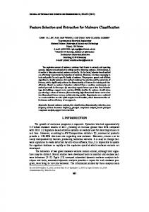
(b) Fig. 1. (a) The mobile robot and (b) controller architecture for experimental purpose
847
848
Byounggon Park et al. / Procedia Engineering 41 (2012) 846 – 853
As shown in Fig. 1, we made a robot system to collect contact sensor data caused by the reaction between the wheels and the ground. The robot’s body consists of aluminum and four air wheels. The size of its width is 24cm and vertical 37cm. Inside system consists of one embedded board for main controller, IMU(Inertial measurement unit), two motor controllers, four motors with encoder and so on. We used serial communication between sensors and the main controller. And Communication between a PC for control and robot is possible by using a WLAN system. The sensors used for terrain feature extraction are 3-axis acceleration, angular velocity and slopes of robot body from IMU. In addition, Motor currents are parameters related to a thrust of mobile robot. So, motor currents in a uniform driving speed are differently printed out depending on terrain types. Thereby, we included motor currents as a sensor data for terrain feature extraction in our study. 2.2. Selection of experimental terrains As shown in Fig. 2, asphalt, soil, gravel and sand terrain are selected as experimental terrains. Asphalt and soil belong to the hard terrain group. In that terrain group, terrain deformation is small and contact ranges between wheel and ground are also regionally small. But that group has a high friction due to hard terrains. Gravel and sand belong to the soft terrain group. This terrain can easily be deformed through various contact phenomena. In a gravel terrain, contact points of wheel are less. Also in case of sand, the number of contact points is constant, however, contact range is broader than other terrains. Because both are easily deformed, and the friction is low. The following section 2.3 deals with analysis results for contact sensor data considering the above mentioned kinds of physical characteristics.
(a)
(b)
(c)
(d)
Fig. 2. Experimental terrains for (a) asphalt, (b) soil, (c) gravel and (d) sand
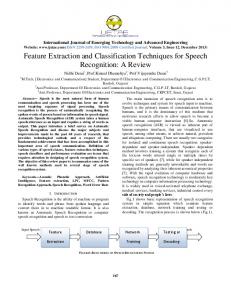
2.3. Analysis of sensor data from each experimental terrain Contact sensor data are collected by the mobile robot while moving, which we designed for experiment on each four terrain types. Fig. 3 is measured data of motor current in two-dimensional plane. X axis is the number of samples and y axis is raw data of sensor outputs. We can easily know that motor current data have different characteristics depending on each terrain. So we analyzed sensor data with these characteristics to extract terrain features. It shows different patterns on periods and amplitudes of positive peaks and negative peaks. These results are caused by physical characteristics of each terrain.
(a))
(b))
(c))
(d) Fig. 3. Motor current data from (a) asphalt, (b) soil, (c) gravel and (d) sand terrain ( X axis : Number of samples, Y axis : Sensor raw data )
849
Byounggon Park et al. / Procedia Engineering 41 (2012) 846 – 853
In the Fig. 3, motor current data of asphalt has regular period and amplitude of peaks. Data from gravel terrain show high peaks by irregular contact between the wheels and the ground. Sand terrain is the most flexible terrain and it has a broad contact area. For this reason, sand terrain has less peak points in comparison with the other terrains. Also, state with no peaks can be seen in a section caused by the slip of the wheels. Data from soil terrain showed characteristics as if medium levels of gravel and sand because soil terrain is mixed with small gravel and sand terrains. We confirmed that other sensor data have also different characteristics depending on each experimental terrain. The following chapter 3 deals with a method of terrain feature extraction from contact sensor data. And we introduce results of verification that terrain features extracted can be used for terrain classification. 3. Terrain feature extraction 3.1. Terrain feature extraction using peak variances As shown in Fig. 4, we developed a method for terrain feature extraction from sensor data based on the results of section 2.3. Contact sensor data have different characteristics on periods and amplitudes of positive and negative peaks dependant on each experimental terrain.
Fig. 4. Algorithm concept of terrain feature extraction using peak variances
To take advantages of these characteristics, positive and negative peaks are extracted from sensor data obtained over a window of time.
X k / X k /1 @0 , dt
X k -1 / X k >0 dt
X k / X k /1 >0 , dt
X k -1 / X k @0 dt
(1)
(2)
X k is a sensor data. Data to satisfy simultaneous Equation (1) is used for positive peak data. Data to satisfy Equation (2) is used for negative peak data.
μ pp ?
u xpp ?
1 n  X pp(k) , n k ?1
1 n (X pp(k) / μ pp )2 , Â n k ?1
μnp ? x u np ?
1 n  X np(k) n k ?1
1 n (X np(k) / μnp )2 Â n k ?1
(3)
(4)
850
Byounggon Park et al. / Procedia Engineering 41 (2012) 846 – 853
o pp
is an average of positive peaks, And is
calculated by Equation (3).
u xpp
X pp , And o np is an average of negative peaks X np . Those values can be
is a variance of positive peaks and
x u np
is a variance of negative peaks. Those values can
be calculated by Equation (4). Two variance data are matched at each x and y axis of a two-dimensional plane. And then terrain groups are formed at a two-dimensional plane as shown in the bottom right corner of Fig. 4. This process is repeated after addition of the next sample data. Positive and negative peak variances obtained in this way are named as a feature of peak variance. In this paper, section n for calculation of peak variances selected 50 samples. As a result of experiments for various sections n , we confirmed that the more section n is broad, the clearer terrain groups are classified. 3.2. Results of terrain feature extraction for each contact sensor Through experiments of several times, we have known that terrain feature data obtained from peak variances have repeated similar characteristics in that terrain groups appear repeatedly in a fixed location in a two-dimensional plane.
Fig. 5. The result of terrain feature extraction from motor current data on each experimental terrains (Dotted rectangle is before enlarged portion, solid rectangle is after enlarged portion)
From these results, we represented a result of terrain feature extraction using motor current data as shown in Fig. 5. Asphalt and soil terrain groups have a small distribution of features of peak variance. On the other hand, gravel and sand terrain groups have a large distribution of features of peak variance in comparison to other groups. As the results of these repeated characteristics, asphalt and soil terrain groups can be classified by features of peak variance obtained from the motor current data. Fig. 6 is a result of terrain feature extraction using acceleration data of z axis of the robot. When we analyze acceleration data in the same way as before, soil and sand terrain groups have a small distribution of features of peak variance. But the distribution of soil terrain group is overlapped with asphalt terrain group. We can expect that features of peak variance extracted from acceleration data of z axis can classify soil and asphalt terrain for similar group because overlapped portion means that those have the same characteristics.
Fig. 6. The result of terrain feature extraction from acceleration data of z axis on each experimental terrains (Dotted rectangle is before enlarged portion, solid rectangle is after enlarged portion)
Byounggon Park et al. / Procedia Engineering 41 (2012) 846 – 853
Fig. 7 is a result of terrain feature extraction using yaw-rate data of the robot. Gravel terrain group has a large distribution of features of peak variance, and the other groups have a small. For this result of analysis, we can know that yaw-rate data contain a lot of information by comparison with the other sensor data.
Fig. 7. The result of terrain feature extraction from yaw-rate data on each experimental terrains (Dotted rectangle is before enlarged portion, solid rectangle is after enlarged portion)
4. Performance comparison of terrain classification according to terrain feature extraction 4.1. Performance comparison of terrain classification using terrain feature of FFT and peak variance Terrain feature of FFT and peak variance are learned by back-propagation algorithm of neural networks. Fig. 8 is experiment results of terrain classification through the back-propagation algorithm. At first, terrain feature data is learned by back-propagation algorithm. Yaw-rate data presented as the best performance among the other sensors were used as terrain feature data. And then, data that is not used for training were classified by back-propagation algorithm as experimental terrain groups. As shown in Fig. 8, both of these methods appeared similar classification rates of terrains. For this result, we can confirm the feasibility of the proposed method.
(a)
(b) Fig. 8. The result of terrain classification using terrain features of (A) FFT and (B) peak variance
4.2. Efficiency comparison of terrain classification considering real-time property To apply a terrain classification system into mobile robots, real-time property is also an important criterion of classification performance, so we compared processing time of terrain classification using FFT feature data with peak variance feature data as shown in Table 1. Due to differences of the number of data that were used as terrain feature data, Computation time of the method that extracts terrain features using peak variances was faster than the method using FFT feature data. For comparison of two methods of terrain feature extraction considering real-time property, we made an index as shown in Equation (5).
851
852
Byounggon Park et al. / Procedia Engineering 41 (2012) 846 – 853 Table 1. The comparison of computational time according to method for terrain feature extraction ( Method 1 : terrain feature extraction using FFT feature data, Method 2 : terrain feature extraction using peak variance data ) Methods for terrain feature extraction
Input No.
Output No.
Computational time (sec)
Method 1
50
10
0.1292
Method 2
50
2
0.0676
E? In the equation (5),
p t-e
(5)
Eefficiency is efficiency of terrain classification, p possibility is possibility of terrain classification, tComputational time
is computational time of terrain feature extraction,
eerror is error rate of terrain classification.
Fig. 9. The Comparison of classification efficiency
In the Fig. 9, we present a result as we applied the Equation (5) to experimental result of terrain classification in the Fig. 8. The gravel terrain group has a similar efficiency of terrain classification in both methods. However, results of the other experimental terrain groups showed that efficiency of the proposed method using peak variances is better than of the exiting method. As a result, efficiency of terrain classification using yaw-rate data was similar in two methods. But we confirmed that the proposed method has more efficiency of terrain classification than existing method considering real-time property. 5. Conclusion In this paper, we suggested a new method of terrain feature extraction from contact sensors. And we verified the proposed method with a feasibility of terrain classification in comparison with the method of terrain feature extraction using FFT feature data. Also, we confirmed that our method is better than the existing method when considering computational time. A future research direction is that we are planning to apply the terrain feature extraction method we suggested into terrain classification research considering conditions of the speed variant. And we will study methods for terrain classification in mixed terrain types.
Acknowledgements The Authors gratefully acknowledge the support from UTRC (Unmanned technology Research Center) at KAIST (Korea Advanced Institute of Science and Technology), originally funded by DAPA, ADD.
Byounggon Park et al. / Procedia Engineering 41 (2012) 846 – 853
References [1] Liang Lu, Camilo Ordonez, Emmanuel G. Collins, Jr. and Edmond M. DuPont, "Terrain Surface Classification for Autonomous Ground Vehicles Using a 2D Laser StripeBased Structured Light Sensor" IEEE/RSJ International Conference on Intelligent Robots and Systems, October, 2009 [2] Seung-Youn Lee, Dong-Min Kwak, “A Terrain Classification Method for UGV Autonomous Navigation Based on SURF” International Conference on Ubiquitous Robots and Ambient Intelligence(URAI), November, 2011 [3] Lauro Ojeda, Johann Borenstein, Gary Witus, Robert Karlsen, “Terrain Characterization and Classification with a Mobile Robot” Jounal of Field Robotics, 2006 [4] Christian Weiss, Holger Frojlich and Andeas Zell, "Vibration-based Terrain Classification Using Support Vector Machines" IEEE/RSJ International Conference on Intelligent Robots and Systems, October, 2006 [5] Christian Weiss, Nikolas Fechner, Matthias Stark, Andreas Zell, "Comparison of Different Approaches to Vibration-based Terrain Classification" Conference on Mobile Robots, September, 2007 [6] Christopher Brooks, Karl Iagnemma, and Steven Dubowsky, "Vibration-based Terrain Analysis for Mobile Robots" IEEE International Conference on Robotics and Automation, April, 2005 [7] D. Sadhukhan. “Autonomous ground vehicle terrain classification using internal sensors” Master’s thesis, Dept. Mech. Eng., Florida State University, 2004 [8] C. A. Brooks and K. Iagnemma, “Vibration-based terrain classification for planetary exploration rovers” IEEE Transactions on Robotics, December 2005 [9] Eric Coyle, Emmanuel G. Collins Jr, Rodney G. Roberts, “Speed Independent Terrain Classification Using Singular Value Decomposition Interpolation” IEEE ICRA, May, 2011
853