data on the distribution of radiance over the sky dome while investigating light interception ...... Series Cameras, Secaucus, New Jersey, 13pp. P a s c o e , D . J .
THE
ANGULAR
DIFFUSE OVER
DISTRIBUTION
SOLAR
T H E SKY
OF
RADIATION HEMISPHERE
By
KATHLEEN B.A.,
THESIS THE
ELIZABETH
STEWART
McMaster U n i v e r s i t y ,
SUBMITTED IN PARTIAL REQUIREMENTS MASTER
FOR OF
1982
FULFILMENT
THE DEGREE
OF
SCIENCE
in THE
FACULTY
OF
(Department
We
accept to
THE
this
the required
UNIVERSITY
OF
Kathleen
STUDIES
of Geography)
thesis
July
©
GRADUATE
as
conforming
standard
BRITISH
COLUMBIA
1984
Elizabeth
Stewart,
1984
In p r e s e n t i n g
t h i s t h e s i s i n p a r t i a l f u l f i l m e n t of
requirements f o r an advanced degree at the
the
University
o f B r i t i s h Columbia, I agree t h a t the L i b r a r y s h a l l make it
f r e e l y a v a i l a b l e f o r reference
and
study.
I
further
agree t h a t p e r m i s s i o n f o r e x t e n s i v e copying of t h i s t h e s i s f o r s c h o l a r l y purposes may
be
department o r by h i s o r her
granted by
the head o f
representatives.
my
It i s
understood t h a t copying or p u b l i c a t i o n of t h i s t h e s i s f o r f i n a n c i a l gain
s h a l l not be
allowed without my
permission..
Department o f
Geofetft-ftfH^f
The
U n i v e r s i t y of B r i t i s h
1956
Main
Mall
Vancouver, Canada V6T 1Y3
D
a
t
e
iSri
Columbia
written
i i
Abstract
The with
use of a video-based
measurements
actinometer
of sky radiance
provide
t h e means
distribution
of d i f f u s e
hemisphere.
Development
measurement radiative not
procedure
regimes
pattern, the
dispelling
sky hemisphere Measurements brightness
the
sky.
radiance been
statistical underlying This techniques type
radiative
the sky high
t o b e made
the
confirm that
radiance
derived
resolution
under
complex
procedures
were
directional
the anisotropy
of the
the d i s t r i b u t i o n
over
a c t as a c a l i b r a t i o n f o r
from
once
useful
discusses
can y i e l d
characteristics measurement
from
imagery of
brightness to
the c a l i b r a t i o n
Functional analysis
most
the video
transformation
procedure
i s presented
f o r determining
the
has
as the
relationship
curves. the advantages
in a climatological
conventional
over
the angular
is isotropic.
the calibration
of system
Linke-Feussner
experimental
any assumption
be d e t e r m i n e d
study
earlier
information
tool
analyses
of d i f f u s e
accomplished.
in conjunction
fast-response,
radiance
The a p p r o p r i a t e may
by a
Investigations into
of diffuse
the
made
radiation
of t h i s
allows
system
f o r determining
solar
i n which
satisfactory.
distribution
imaging
application
valuable
of using
a n d shows
information
otherwise techniques.
video how
concerning
unavailable
with
imaging this
iii
Table
of
Contents
Page
Abstract Table
i i
of Contents
i i i
List
of T a b l e s
viii
List
of F i g u r e s
xi
List
of Symbols
xv
Acknowledgements Chapter 1.1
One
-
xviii
Introduction
1
Objectives
1
1 .2 Background Chapter 2.1
Two
1
- Instrumentation
Measurement
10
of D i f f u s e
Solar
10
R a d i a t i on 2.1.1
2.1.2
Recording
the D i f f u s e
Radiation
Signal
Analysis
of
Associated Measurement Solar 2.1.2.1
11
the Error with of
12
the Diffuse
Radiation Analysis
of
Associated 2.1.2.2 A n a l y s i s
Recording
with
of
Associated
the Error the
Sensor
the Error with
the
Instrument
12
13
i v
2.1.2.3
Error
Associated with
Measurement Solar 2.2
Determination from 2.2.1
of
the
Diffuse
Radiation
of
Brightness
Video
Imagery
Video
Camera
and
Values
Monitoring
System 2.2.1.1
Video Lens
Camera, and
2.2.1.2 V i d e o Chapter 3.1
Three
-
Field 3.1.1
View
Measurement
3.3
E s t i m a t i o n of Video
3.3.1
the
4.1
of
the
of with
Error
Determination
the
Error
Brightness
Procedure
of
the
Relationship
Radiance
and
Brightness
Values 4.1.1
of
Determination
Calibration
between
in
in Registration
Calculation
-
Error
Coordinates
Level Four
Analysis
System
Associated
Chapter
Site
Procedure
Inherent Sky
Procedures
Factor
Assessment
3.3.2
Framestore
Measurement
3.2
the
Filter
Experimental
Sky
Fisheye
Regression
Analysis
V
Page 4.1.2 4.2
Functional
Verification
Analysis
50
the
54
of
Calibration
Procedure 4.3
Validity Scan
Chapter
Five
of
Approach
5.2
-
The
Angular
63
the
Radiance
i n the
Point
the
on
for
Value Sky
over
73
of
to
of
the
Distribution Different
a
a
Diffuse Sky
of
Solar
Radiance
Sky
Values
76
Conditions 82
5.3.1
Clear
5.3.2
Overcast
5.3.3
Partly
Previous
76
Hemisphere
Application
Comparison
73
Image
Distribution
for
of
Radiation
Translating
5.2.1
5.4
Solar
a Method
Radiation
5.3
Distribution
Determining
The
Partial
Data
Diffuse 5.1
using
Sky
Conditions Sky
Cloudy of
82
Conditions Sky
Conditions
Results with
86 95 104
Studies
5.4.1
Clear
Sky
5.4.2
Overcast
5.4.3
Partly
Radiance Sky
Cloudy
Distributions
Radiance Sky
Distributions
Radiance
104 111 115
Distributions Chapter 6.1
Six
- C o n c l u s i o n s and
Assessment
of
the
Recommendations
Experimental
120 120
vi
Procedures 6.1.1
Critical
Assessment
Measurement in
6.2
this
Used
Study
Site
6.1.1.2
Assessment
Considerations of
Instrumentation
of R e s u l t s
6.2.1
Clear
6.2.2
Overcast
6.2.3
Partly
6.2.4
Radiance
6.3
Techniques
6.1.1.1
Summary
of
Sky
Cases Sky
Cases
Cloudy
Sky
Cases
Maps
C o n c l u s i o n s and
Recommendations
References Appendix
I - Assessment of
Lens
Imaging Test
and
Video
System
for Axial
Camera AI.1.2
Characteristics
the Fisheye
Camera
Al.1
of the
Symmetry
of Fisheye
Lens
Test
to Confirm
Projection
Equi-Angular
of F i s h e y e
Camera
Lens AI.2
Determination a
AI.3
Video
of t h e Shape of
Image
Determination
of t h e Shape of
the A c t i n o m e t r i c Field-of-View
a s Seen
on a
Video
V
11 Page
Image Appendix
II
- Regression Versus for
Corrected
Clear,
Cloudy
Results
Radiance
Brightness
Overcast
Skies
of
and
Partly
140
vi i i
List
Of
Tables
Page Table
2.1
Recorder
Error
Diffuse Table
2.2
Table
2.3
Radiation
Probable with
Radiances
Outside
3
Composition
(Wm~ sr~ ) 2
i n the Solar
From
2
3.1
Record
Table
3.2
Sequence
of O b s e r v a t i o n s
Sampling
Grid
of F i e l d
Regression
2
Table
4.2
_ 1
Table
4.3
4.4
and
Results
2
and Radiance
f o r Overcast
Brightness
Using
47
Values
Sky
and
Data
48
Radiance
1
Results
Using
Results Show
Skies
(Wm" sr~ )
Radiance Table
37
)
Regression Skies
33
i n Second
for Clear
Brightness
Corrected
Values
(1969)
Observations
Results
Regression Using
22
Kondratyev
Table
Corrected
1
of D i f f u s e R a d i a t i o n
(10~ cal/cm min). 6
1 6
and the S p e c t r a l
2
(Wm" sr
1 5
the Atmosphere
(10~ cal/cm min)
4.1
a
Signal
Distribution
Spectrum
Table
with
Relative Errors Associated
Sample
Energy
Associated
for Partly
Corrected
Values
Cloudy
B r i g h t n e s s and
(Wm~ sr 2
_ 1
)
of Functional A n a l y s i s to
Variation Measured
between
Radiance
49
Predicted (Wm~ sr~ ) 2
1
53
IX
Page for
Clear, Overcast
Cloudy Table
4.5
Results
Sky
Table
Table
4.6
4.7
of
Transformation to
of
4.8
Brightness
to
Cloudy
Conditions
Results
4.9
Sky of
Table
Table
4.10
5.1
Radiance
to
Radiance
Results
Cloudy
Regression
Data
Clear
from
for
56
Partly
Transformation
Regression
Sky
55
from
for
57
Overcast
Conditions
Partly Table
for
Transformation
Brightness
Table
Radiance
from
Conditions
Results
Sky
Partly
Conditions
Brightness Sky
and
Sky
showing
Obtained
and
66
Conditions
Analysis Results
Conditions as
for Clear
with
Measurements
(S),
Measurements
(NS).
for
Clear
Variation
in
Simultaneous
Asynchronous
Regression
Analysis Results
for a
Cloudy
(JD339)
Obtained
Sky
f o r Data
Simultaneous
Measurements
Asynchronous
(NS)
Values
of
(Using
Eqn.
for
Measured
Certain
Skies, (Zenith
5.11)
Observed Angle
(S),
on 74°)
Partly
71
with
and
Measurements. and
11 3
Predicted
Radiances
Zenith
71
Angles January
(Wm~ sr~ ) 2
for 20,
1
Overcast 1984
Page Table
Al.1 a
Pixel of
Table Al.1b
Coordinate
t h e 10° T a r g e t s
Video
Image
Pixel
Coordinate
of
Positions
Positions
t h e 10° T a r g e t s
Image W i t h
Visible
Visible
f o r Each
1 38
on t h e
f o r Each on
t h e Camera R o t a t e d
the
Video
by 9 0 °
1 38
xi
List
of
Figures
Page Figure
Figure
Figure
2.1
2.2
2.3
Spectral
Sensitivity Characteristics
of
the
to
the V i d i c o n
Video
ER
Newvicon
Camera
3.1
and
Filter
Curve
Spectral
Distribution
View
for Clear
of V i d e o
Relative
Camera
Response
Radiation Figure
Camera
18
Spectral
21
Diffuse
24
of
Skies
Camera
in
Monitoring
29
Position Figure
3.2
View
of
Figure
3.3
Design
Figure
4.1
Contour
Field of
for Figure
4.2
a
4.3
an
Figure
4.4
a
4.5
and
Cloudy
of
Sky,
40
Differences
Between
58
Radiances
Differences
Predicted
of
Between
61
Radiances
Sky Differences
Predicted
Results
December
Regression
30
Roof
Grid
P a r t l y Cloudy
Regression Scan,
Figure
and
Plot
Measured
the
Predicted
Overcast
Contour
for
of
on
Sky
Plot
Measured
Figure
and
Clear
Contour
for
Sampling
Plot
Measured
Site
62
Radiances
Sky for a
20,
Results
Between
Clear
Sky
65
1983 for a
December
5,
Partly 1983
68
1
XI
Figure
5.1
Geometry
Figure
5.2
Frequency Radiance
of Sky
Histograms for Clear
a) December
Figure
5.3
5.4
20,
Histograms f o r Overcast
Figure
Figure
Figure
Figure
5.8
5.9
5.10
5.11
Predicted
Skies
20,
1984
b) l 3 4 0
LAT
January
20,
1984
Frequency
b)
Histograms for Partly
of
Predicted
Cloudy
Skies
1983 12,
13,
1984
and
1983
Sky R a d i a n c e
1320
Clear
5,
January
September
Clear
for 5.7
of
January
for
Figure
1983
LAT
c)
5.6
and
a ) 1320
and
Figure
1983
Frequency
a) December
5.5
Predicted
Skies
21,
Radiance
Figure
of
b) A u g u s t
Radiance
Figure
Hemisphere
Distribution
LAT August
Sky R a d i a n c e
21,
1983
Distribution
1356
LAT December
20,
Overcast
Sky R a d i a n c e
Distribution
for
LAT
1013
January
Overcast
Sky R a d i a n c e
for
LAT
1033
January
Overcast
Sky R a d i a n c e
for
LAT J a n u a r y
1126
Overcast
Sky R a d i a n c e
for
LAT J a n u a r y
1320
Overcast
Sky R a d i a n c e
20,
1983
1984
Distribution 20,
1984
Distribution 20,
1984
Distribution 20,
1984
Distribution
xi i i Page for Figure
5.12
Partly for
Figure
5.13
5.14
for Figure
5.15
for Figure
5.16
for Figure
5.17
for b) Figure
Figure
5.18
5.19
a)
LAT
Cloudy
1417
Clear
LAT
Cloudy
1246
Partly
LAT
Cloudy
1148
Partly
LAT
Cloudy
1116
Partly
LAT
Cloudy
1449
Partly for
Figure
1340
LAT
Sky
Sky
Zenith
20,
January Sky
12,
Distribution
Sky
3,
Distribution
Sky
3,
Distribution
Sky
5,
Distribution
Distribution
13,
70°
103
1983
Distributions
Angle
101
1983
Radiance
September
99
1984
Radiance
December
98
1984
Radiance
February
96
1984
Radiance
February
Angle
1984
Radiance
Luminance
Zenith
Standard
January
105
and
50°
Distributions
Clear
Sky
Radiance
Angle
35°
and
Clear
Sky
Normalized
b)
of
f o r a)
Zenith
Normalized
107
Zenith
Angle
55°
Radiance
109
Distributions Figure
5.20
Overcast for
Sky
Zenith
Radiance
Angle
5.21
Overcast
Sky
Figure
5.22
Radiance
Distributions
Figure
5.23
Cloud
Partly
Cloudy
Distribution Figure
AlI. 1
Regression
114
Distributions
116
63°
Figure
Cirrus
Distribution
Radiance
During
117
Cover Sky
Radiance
for Zenith
Line
of
119
Angle
Radiance
64.5°
and
141
xi v
Brightness 0916 Figure
All.2
All.3
Brightness
for a Clear
All.4
All.5
Figure
All.6
All.7
29,
Brightness
for a Clear
LST J u l y
Sky
of Radiance
30,
Line
Brightness
for a Partly
Sky
of Radiance
1125 L S T A u g u s t
29,
Regression
Line
Brightness
for a Partly
and
Cloudy 1983
of Radiance
1416 L S T A u g u s t
27,
1983
Line
of Radiance
Brightness
f o r an O v e r c a s t
1250 L S T A u g u s t
27,
Regression
Line
of Radiance
Brightness
f o r an O v e r c a s t 27,
and
Cloudy
Regression
LST August
and
1983
Regression
0921
and
1983
Line
Sky Figure
of Radiance
Regression
Sky Figure
LST J u l y
Sky
29,1983
Line
1118 Figure
LST J u l y
Regression
1631 Figure
for a Clear
and Sky
1983
1983
and Sky
XV
List
of
Upper
Symbols
Case
Roman
A
projected area
A'
area
CS
asynchronous
D(z)
horizon-darkening
E_-^
total
probable
under
clear
total
probable
under
partly
total
probable
error
under
overcast
skies
E
error
variance
of b r i g h t n e s s
Ey
error
variance
of d i f f u s e
LAT
local
apparent
time
NPIX
number
Ep_
E
Q
v
on a h e m i s p h e r e
on t h e d i g i t i z e d
planar
radiance
skies
image
(metres ) 2
measurements
f o r an e q u i a n g u l a r
of a
lens
brightness
value
measured
brightness
value
measured
value
measured
(counts)
error
cloudy
of p i x e l s
2
and b r i g h t n e s s
factor
error
(metres )
of a skies
(counts)
of a brightness (counts) values
radiance
(counts) values
(WirT sr~ ) 2
1
(hours)
corresponding
to actinometric
field-of-view R R
distance 0
radius
from
point
of d i g i t i z e d
R * 0
semi
major
axis
RMS
root
mean
S
actual brightness
S
synchronous
SOC
Standard
to centre planar
of planar
square
error
image image
(Wm" sr 2
of an e l e m e n t
radiance
Overcast
on p l a n a r
Sky
(metres)
(metres) (pixels)
_ 1
) of a
and b r i g h t n e s s formula
image
scene
(counts)
measurements
xvi
T
temperature
(°C)
X
measured
X'
corrected brightness
X^
mean
X^_j
j t h of m
X
mean
Y
measured
diffuse
radiance
(Wm
Y'
corrected diffuse
radiance
(Wm~ sr
Y
mean
Y
predicted diffuse
brightness
value
value
of a
value
brightness
diffuse
value
observations
value
radiance
of b r i g h t n e s s
2
- 1
_ 1
)
- 1
)
)
(Wm~ sr 2
Roman
of f u n c t i o n a l
line
(Wm
a
intercept
value
of r e g r e s s i o n
line
(Wm
b
empirical constant
b^
slope
of f u n c t i o n a l
line
(Wm~ sr~ )~
1
b
slope
of r e g r e s s i o n
line
(Wm~ sr~ )~
1
i n Standard
c
empirical
r
correlation
coefficient
coefficient
of
2
x x
0
y y v
0
variable
1
value
r
(counts)
sr~ ) 2
(Wm~ sr
Case
_ 2
intercept
r
point
(counts)
a^ r
(counts)
(counts)
radiance
Lower
point
of a sampling
of i t hbrightness
replicate
sampling
Overcast 2
2
1
1
_ 2
sr~ ) 1
_ 2
sr
_ 1
Sky
) formula
constant
determination
abscissa
pixel
coordinate
abscissa
value
of centre
ordinate
pixel
coordinate
ordinate
value
of centre
electrical
output
on d i g i t i z e d coordinate
on d i g i t i z e d
on d i g i t i z e d coordinate
of video
camera
image image
image
on d i g i t i z e d
(Volts)
image
xvi i
z
zenith
angle
(degrees)
Lower
angular
a'
temperature
calibration
coefficient
7
gamma
value
of
camera
X
ratio
of
(j>
azimuth
p
6
R
sky
of
Greek
a-
0__
width
Case
Newvicon
error angle
view
i t h annulus
(radians)
(7 = 1 . 0 0 )
tube
variances (degrees)
factor
d i s t a n c e from
the
centre
projected
vertically
elevation
angle
above
of
through the
the
area
the
horizon
sky
A
to
a
normal
hemisphere
(degrees)
xvi i i
Acknowledgements
I
would
support this
like
given
study.
Steyn
for
special
to
advice
and
and
Loudon,
a
Natural
contract
the
helpful
C.
Portions the
be
my
and
the
Sciences with
the
s u p e r v i s o r , Dr.
the
J.E.
goes
to
M.
Roseberry
programming others
suggestions, R.
Roberts,
research and
guidance Hay, to
c o n s t r u c t i v e comments.
study,
Raphael, of
acknowledge
s i n c e r e a p p r e c i a t i o n goes
computer
Throughout
S.
my
gratefully
acknowledgement
assistance
comments
me
Also
his
to
were
were
Dr.
D.G.
Another
whose
technical
invaluable to
me.
me
with
namely:
S.
Grimmond,
C.
funded
Engineering
Canadian
during
provided
and
critical
Souch. by
Research
Atmospheric
and
a
grant
from
Council
and
Environment
by
Service.
1
Chapter
One
Introduction
1.1
Object ives The
aim
procedure solar
of
radiation
patterns
i s to
A derived
to
examine
of
sky
compares
partly attempt
under
method
more
these
i s to
cloudy to
the
extend
maps
are
results
this
work
Background
produced clearly.
the
analyzing
a with
a
diffuse
objective and
of
this
suggest
characteristics
relatively results
with
c o n d i t i o n s and the
knowledge
radiance
any
those
under
under of
of
the clear
earlier the
overcast
diffuse
solar
regimes. from
i s presented
i n an
of
stationary,
observations
radiative
imagery
of
system
producing
Another
record
sky
complex
video
imaging
sky
necessary.
under
for predicting
coordinate
1.2
aim
diffuse
varying
observational technique
radiance
of
development
of
of
dome.
attempts
i n an
of
means
be
further
from
aim
to
complex
radiation
the
appear
c o n d i t i o n s and
skies,
video
that
distribution
more
sky
a
this
study
A
resolution the
under
i n v o l v e s the
with
an.experimental
distribution
hemisphere
combining
over
develop
angular
assess
improvements
studies.
sky
procedure
high
i s to
the
observations
fast-response,
This
the
programme
actinometric
radiance
over
This
measurement
study
research
for determining
conditions.
sky
this
attempt
the
brightness
and to
polar
display
the
data
2
Increasing
research
on
the
effective
radiation
incident
on
sloping
surfaces
fact
the
of
diffuse
radiation,
of
that
the
total
role
incident
shortwave
load,
understood.
Designers
of
solar
researchers
interested
in
catchment
studies
have
paid
intensity
across
Currently
the
an
assumed
(Morris the from
beam
radiation
solar
results. the
into
radiation
the have
Several
assumptions
distribution.
Kondratyev
assumption
of
and
(1970).
Ohmura
an
isotropic
empirical
analysis
realistic
pattern
Morse
and
radiation
is
and
may
type
Sun
hence of
the
from
and
the
and
those
snowmelt
sky
of
Brunger,
component
contrasts which
fully
or
and
the fraction
distribution
(Hooper
component
the
yet
systems
diffuse
This
determined
substantial
not
the
over
solar
its 1980).
rests
on
hemisphere with
may
be
analyses
of
calculated
geometrical inclined
surface
(Hay
and
1980).
Investigations diffuse
1971).
between
to
the
distribution
equations
relationships
of
a
is
of
acknowledged
evaporation
hemisphere
determination
has
collector
attention
sky
Lawrence,
precise
Davies,
the
radiance
and
direct
little
modelling
was
not
be
been
al.
of
varying
to
approximate
adopted
pattern
convenient this
with
invoked
(1955)
radiance
support
(1958)
as
the did
Gamier
mathematically, model
suggested
concentrated
approximated
Sun-centred
undertaken
have et
distribution
and
a
more
sought.
Czarnecki
largely
been
sky
Although did
directional
or
as
in
the
that
diffuse
region
around
directional
heliocentric
model
can
radiation. greatly
the
Sun
This
3
overestimate
the d i f f u s e
and
1980).
Brunger,
assumption values
heliocentric values
much
highest Morris
Later
of Morse
of energy
by N o r r i s
were
those
noted
surface
that
day o r i g i n a t e d
(1966)
against
measured
f o r monthly
mean
values cover
only
(Hooper
tested the
that
the cloud
found
slopes
and found
for daily
when
(1971)
on a c l e a r
(1958)
yields errors
than
and Lawrence
component
studies
inclined
assumption
errors
f o r Sun-facing
and Czarnecki
on a n
larger
radiance
the radiance
and t h a t was
the
greatest.
57% o f t h e d i f f u s e
within
60° o f t h e s o l a r
disk. A
fixed
radiation
combinational
as
isotropic,
was d e v e l o p e d a
by Hay
variable
ratio
radiation.
This
transmissivity index
a n d was
error
(RMS)
(1978).
of the d i r e c t
and Brunger
describing
both
This
was
factors: component; to
an
based
(1980)
that
sufficiently
normalized
stable
developed
component;
clear
to allow
the sky
as h e l i o c e n t r i c
improved
by
assuming
the atmospheric as an
and root
a three
which
was
anisotropy mean
square
three
results
(eg. Steven,1977)
for consistent
of
brightening
Their
sky radiance
of
distributions.
superposition a horizon
component
capable
sky radiance
component.
findings
half
1980).
on t h e l i n e a r
other
bias
(TCCD) m o d e l
and a c i r c u m s o l a r
later
used
both
and overcast
isotropic
substantiate
suggested
clear
half
beam c o m p o n e n t
and Brunger,
distribution
treated
and h e l i o c e n t r i c d i f f u s e
model
t o improve
continuous
model
I t was
isotropic
anisotropic
found
which
and the remaining
between
(Hooper
Hooper
model
seemed
which
distributions are mathematical
4
modelling
(Hooper
and
empirically-based data by
base
not
with
being
As
radiance
skies
and
clear
measurements
technique
sky
the
described
obtained
points
in the
system
of
of
over
Valko sky
various
provided
the
and
directional
radiance.
Hooper
developing
an
automatic
radiometer
to
measure
capable
creating
aquisition was
system
designed
radiance
and
a
was
primarily
under
partly
Two
radiance
sky
scanning
radiance.
substantial entirely to
study
cloudy
other One was
form
and
This
was
the
that
scanned
at
121
using
a
radiometers, The
the
using
and
as
data sky by
sensitive system
the
of
of
an
problem
a
scanning
well
a
measurement
distribution
c o n d i t i o n s as
of
variations
base,
a
to
azimuths
system
of
utilized
computer-controlled. the
in several
devices.
and
diffuse
radiance
study
approached
data
as
standard
silicon-diode
(1982)
of
characteristics
Sun-tracking
Brunger
of
angle
This
distributions
sky
define
e l e v a t i o n s and
other
the
state,
out
the
series
procedure.
pyranometers,
radiometer
carried
zenith
dome.
of
well
distribution
A to
as
steady
determine
spatial
similar
accuracy
skies.
been
to
solar
sky
the
approximately
pattern.
the
any
calibrated
cloudy
turbidity.
the
a
at
absolute
been
in order
of
with
by
angular
(1980) where
rotating
of
the
the
preserved
attempted by
an
attempted
effects
intensity
had
partly
radiance
i n terms
which
programmes
model
of
As
limited
c o n d i t i o n s have
(1977)
were
distributions investigate
the
represent
such
1980).
i t was
analyses
Steven
standard
radiant
which
under
studies.
model,
a p p l i c a b l e to
clear
measurement
Brunger,
was
data This
work
diffuse under
the
5
better-documented presented
the
of the angular
overcast
Kimball
s k i e s have
and Hand
brightest
(1922)
area
a quarter
an
e m p i r i c a l formula
or less
Standard
data
pattern
range,
light
recent
to test
spectral
radiance
function
similar
significant
high
distribution atmospheric solar
energy
determining
to
Sky
have
been
spectrum t h e human
measured
frequently.
taken
by S t e v e n
by
a n d i s known a s (1971)
required while
found
that the
a narrow
spectral
He
under
noted
rapid
overcast conditions. and Unsworth
t h e SOC
well
decreased
represented
He
over
formula.
worked
clouded sky,
t h e s k y dome
by p l a n t s .
a broad
between
formula
(1980), and
waveband,
found
that
but there
might
be
radiance
and
a
luminance
skies. set describing the angular
solar
conditions i s a applications. the intensity i s that
over
between
over
t o t h e SOC
of d i f f u s e
was
Grace
the agreement
data
This
(SOC) f o r m u l a .
distribution
radiance
and the r a d i a n c e
(1942)
investigation
quality
out less
and Spencer
t h e SOC
of overcast
of d i f f u s e
f o r a densely
of radiance
with
differences
distributions A
that
of h i s observations,
designed
the
by Moon
i n the radiance
A more
carried
interception
corresponded
changes
been
at the horizon.
Overcast
investigating
distribution
found
on t h e d i s t r i b u t i o n
mean
b u t few r e s u l t s
was a t t h e z e n i t h
to
the
sky cases
thus f a r .
Studies below
clear
this
radiation
frequent The
eye f o r a greater
immediate
provides part
varying
requirement
distribution part
under
in evaluating
practical
use of
i n the v i s i b l e the visual
of t h e day
part of
environment
(Sastri
and
6
Manamohanan, attempts Earlier
to
1975). use
that
fluxes. the be
i n the
sky
first
between
et
the
energetical
and
luminous
compared,
observed
due
the
applicability
of
(1977)
d e t e r m i n a t i o n of
clear
the
skies,
previously
(1977) over
used
34
a
requiring
on
a
be
found
that
adequately atmospheric
minutes
units,
to
diffuse from
were
a
taken
a
luminance
conditions.
He
to
general by
of
distributions patterns
developed
radiation
independent standard,
of
clear
sky
measurements
McArthur
c o u l d be
a
These
angles.
by
spatially
radiance
diffuse
radiance
further
with
Steven
scan.
be
zenith
Steven
hemisphere,
enabled
radiation
both
the
to measure
respect to
solar
of
these
each
found
may
correspondence
study
sky
of
intensities
radiance
the
series
step
shortwave
the
They
radiation
distributions.
This
long
for different was
with
of
compare
across
levels.
on
lack
to complete
s u r f a c e and
methods.
distribution
responses
actinometer
normalized
based
work
involve
linear
luminous
radiation
standard
attempt
is a
angular
supposed
transect
turbidity
produced This
40
were
distributions to
in a
horizontal
atmospheric
the
Linke-Feussner
about
measurements
the
p u b l i s h e d luminance
points
far
intensity.
quantitative
photometric
d i d not
there
different
Because
of
of
a
radiant
and
diffuse
instruments.
the
of
although to
the
and
energetical
properties
on
so
a l . (1955) d e s c r i b e d a
approximation
the
not
presented
luminance
Hence,
directly
was
Kondratyev
between
relationship
techniques
c o n v e n t i o n a l r a d i o m e t r i c measurement
r e s e a r c h by
relationship noted
The
and
(1978)
estimated
for varying
sensitive,
who
7
fast-response, accommodate changing
photographic
the
spatial
cloud
took
fisheye
during
measurements. form
measured the
radiance
addressed from
the
f o r haze
the
of
Even are
the
need
accurate
for
Hay,
being
dome a n d
are
Dave
radiative
a
into
approach
able
to
the
in
and
had
provide
most
an
complex results
agreement
Dave
a
with
This
i n good
transfer
to
(1978)
correlated
(1981).
dominant
with
quantitative
point-of-view
luminance,
measurements
radiance
even
The
(1980) by
highly
of
of
negatives
1978).
represented.
some the
techniques
with
(1981)
the
atmosphere
focussed
wavelength
diffuse
photographs. actinometer
have
the
very
to
The
radiance These used
limitations
i s attempting stage
described
inadequacies.
the
reduction
be
to
rapidly
McArthur
actinometric
to
of
camera
photographic
sky
Hay
SLR
attempt
time
1978).
mm
methods
models
measurement
the
of
and
the
as
technique data
the
response
Hay,
35
density
and
of
an
and
on spectral
radiation.
without
calibrate
hence,
of
sky
the
not
problem
a
the
visual-air-quality
computations purity
be
in McArthur
computations
of
of
was
complexities
long
and
sequence
previous
mapping
which
previously restricted
(McArthur
over
the
using
film
conditions could
presented
by
a
showed
instantaneous
temporal
(McArthur
Reduction
advantage
sky
had
photographs
lens
digital
which
conditions
all-sky
and
c o n d i t i o n s and
instrumentation cloudless
technique
avoid
i s hampered
by
approach
obtain
that
the
(McArthur. by
is
measurements
calibrations to
McArthur
the
the
are
(1978)
restricted
i n order only
to
as
measurements
and
photographic and
length
Hay, of
1981). time
The
required
8
to
digitize
analysis
photographs
to
The
(1
h.,
40
s m a l l e r - s i z e d data
most
recent
mins.)
to
be
used
radiometric
( a c t i n o m e t r i c ) measurement
video-based
system
equipped
with
type
of
from
the
video of
a
single
their The
video
processing
and
field
framestore, displayed
video
storing
of
a
video
(intensity)
contours
Cannon
and
Dwyer
entire
sky
hemisphere
immediately. stored
on
but
also,
light
has
to
techniques
the used
for
to
limitations
of
data
the on
the levels,
the
video
after
this
the
analyze be
data
image
map
the
the
data
conveniently
and
archiving.
only
purposes,
were
system,
effectively
not
a
iso-luminance
With
might
assess
Dwyer,
from
the
future analysis
research
and
gather
images
digitized
intensity
could
and
passed
which
shortly
1981).
they
video
ability
(Cannon
to
obtained
This
digitizing,
data
so
camera
density
and
of
is a
(derived
(Cannon
Digitizing
processing
found
for daylighting
in space Due
tape
the
The
different
Dwyer,
same
and
i n s t a n t a n e o u s l y and
Digitized
magnetic
"fluxmapper"
and
(1981)
information
be
luminance
capable
time.
video
fisheye lens.
scene
with
radiation
vidicon
monitored
monitor.
might
a
the
the
was
solar
equal
with
unit
into
computer
(Cannon
a
real
television
of
within
video in
using
imaged
signal
processed
rapid
digitized
be
location
facilitated
is
to
limits
in conjunction
of
projection
objects
framestore,
now
on
allows
image)
1981).
through
'fluxmapper'
orthographic
projection
regardless Dwyer,
an
this
sets.
technique
or
and
the
the
The
quantity,
quality
of
1981). radiometric the
measurement
directional
distribution
9
of
diffuse
solar
paragraphs, making
these
sky cases
have
(1969),
Grace
(1971),
of
study
Even
the
mapped The
camera
(1981).
photographic since
there
video
images
Because
of
radiation possible luminance video
the as
to
to
and
system, This
the
taken
and
distribution changing
or
more of
great
rapidly
characteristics of
of
all-sky
Rondratyev McArthur's response
time
photographs.
distributions
could
sky
that
study
utilizes
described
improvement
over
by
now
the
d i s c u s s e d i n McArthur i n time
(1978),
between
when
results
are
obtained.
between
visible
and
total
the
(1978),
i t is
a
Cannon
measured
procedure
diffuse
present
reduction
actinometric
precise
complex
with
to
d i s c u s s e d i n McArthur
i n f o r m a t i o n from
for a
for
the c o n v e n t i o n a l
i n the
technique
significant
The
under
(1980).
problem
radiation
similar
is a
relationship
flux.
work
efficient
1978).
developed
combine
or
radiance
Unsworth
overcome
preceding
very
skies
i n the
the
shortwave
indeed
radiance observations with
video
information i s representative
radiation allow
are
cloudy
technniques
digitizing is a
i n the
proved
complex
diffuse
(McArthur,
Dwyer
to
not
supplementing
complex
technique
The
alluded
measurement
video-based and
attempted
most
have
Steven
i n s t r u m e n t a t i o n by
radiometric
be
been
described
partly
conditions.
such
(1978)
as
procedures
o b s e r v a t i o n s under
changing of
radiation
images of
the
and total
followed in this
representation
of
the
radiance p a r t i c u l a r i l y conditions.
assume
that
shortwave study
will
angular under
rapidly
the
10
Chapter
Two
Instrumentat ion
2.1
Measurement A
Kipp
76-0319) These
and
was
of
Zonen,
used
and
Solar
Radiation
Linke-Feussner actinometer
t o make m e a s u r e m e n t s
measurements
calibration
Diffuse
were
carried
verification
of
of
(Model
diffuse
out
solely
the
distributions
No.
radiance.
for purposes of
of
sky
radiance. The radiant
actinometer energy
conditions. six
accurately
Built
massive
become
and
act
body
which
rings
affect
Moll
be
occurring readings
acts
subject
near of
compartments,
the
the
as
a
one
of
compensating
to guasi-adiabatic
thermopile surface
instrument are
known
the
to
This which
i s screened
from
However, i t
pressure
be
the
thermopile
device.
(IGY,
These
inside
1958).
which
of
thermopile
a i r currents
compensated
two
may
towards
specially
into
consists
diaphragms.
(IGY,
is
so
smaller
as
measure
turbulent
body
thermopile
a
and
the
function
turbulent
to
relatively
the
uses
radiation
even
stability,
which
to eliminate
instrument
still
under
progressively
could
divided
instrument designed
to ensure
copper
openings thus
i s an
changes
1958).
The
independent
of
wavelength. The
body
accurately the 0°
body to
of
the
sighting
to monitor
40°C
(IGY,
actinometer the
Sun
and
temperature
1958).
The
i s equipped with
a
a
thermometer
fluctuations
instrument
with
within
i s mounted
device set a on
for
inside range a
of
stand
11
fitted
with
increments
of
0.1°.
filter
instrument Coulson
for zenithal actinometer
positions
over
shows
were
in
movements,
1° scaled
i s weatherproofed
in
with
and
with
one
taken
a
built-in
metal
using
a
filter
shutter.
quartz
ring
For
filter
this
made
i t s transmission properties allow
the 99%
range
0.20/iin-3 . Ojum
response
actinometer
Environment
Service
experiment.
i n 8-10
was
to
calibration
resulted
(IGY,
1958).
seconds,
2.1.1.1 The
sr
and
at
of
92% This
according
to
an
diffuse
1
m
Atmospheric
Ont.,
before
constant with
2
of
an
the
resulting
start
from
angular
0.417MV(Wm~ sr~ )~ . 2
determination
equivalent
the
Diffuse
radiation
solid
voltmeter
sensitivity
a
this
(Hewlett-Packard
1/2
Radiation
signal
4
for
_
radiance
Hewlett-Packard
accuracy
Downsview,
16.9AiVW
i n the
the
of
an
half
1
This
1
equivalent
angle
of
5.08°
respectively.
Recording
has
by
calibration
isotropic
aperture
0.0247
calibrated
The
investigation
uniform
was (AES)
sensitivity
and
is divided
(1975).
The
that
which
i s equipped
ultrasil;
transmission
the
The
measurements
homogenized
of
control
actinometer
four
study,
a
circle
plating.
The with
azimuth
and
intervals chromium
an
digit
was
voltmeter of
1 M V on
range
i s quoted
Manual,
1979).
as
Signal
monitored (Model a
20
3466A).
mV
±0.05%
with
range +
3
a This and
digits
the
12
2.1.2
A n a l y s i s of of
2.1.2.1
to
there
been
has
Robinson
i s more
temperature
the
a
( i n degrees
s t u d i e s by
calibration
not
readings
by
0.2%
per
calibration of
the
acceptance
aperture
normalized
however,
Measurement
the
in this
Sensor
study
1958).
this
is
However
accuracy
conservative
on
the
the
as
estimate,
estimate
C e l s i u s ) and of
Forgan
the
of
by
study, will
the
approached
c o n d i t i o n s of
much
the
be
and
zero
AES,
for
(Coulson, suggest
smaller the
in
the
where
solar 1975).
that and
the
so
data.
manufacturer's
used
an
under
The
10.16°
vertical
20°C
for
a'(T-20))
a'=0.002
(1980)
be
+
factor
i t As
value
error
temperatures
can
affect
°C.
out.
of
(1
temperature-correct
actinometer
carried
calibration
factor
c o r r e c t i o n s for other
was
instrument
the
with
(IGY,
of
more
by
dependence
conditions
the
±1%
actually
to
tested during
Hence
sensitivity
a
and
may
necessary
temperature
During
used
temperature
Pascoe
coefficient
deemed
analysis.
that
i s expressed
Empirical
the
of
dependence
at
of
accuracy
temperature
was
Associated
empirical testing
radiation
this
with
reasonable.
radiation
not
Error
actinometer
suggests
i s temperature
was
the
an
no
(1966)
The
T
have
Associated
Radiation
Linke-Feussner
estimated
direct
Error
Diffuse Solar
A n a l y s i s of
The
±2%
the
isotropic
analysis
total
outside
the
of
In
response angular
anisotropy
the
angular
radiation
resulted
angle.
horizontal
radiative
analysis
in
other of
words,
the
limit.
should
an
If
exist,
there
1 3
could
be a n e r r o r
associated with
actinometer
could
total
of aperture
angle
During
this
undertake it
be
study,
sensitive
would
were
respond
error
than
sources
to these
n o t t h e means
of such
n o t be g r e a t e r
measurement; the
to radiative
and c o u l d
there
an a n a l y s i s
each
sources.
available
and i t w i l l
the quoted
beyond t h e
to
be a s s u m e d
overall
accuracy
that
of the
act inometer. Another in
alignment
radiation
true
also
source
an e r r o r
t o any change
for anisotropic
assumed
of e r r o r
of the actinometer.
conditions,
contribute be
possible
Once
again,
i n alignment
in voltage radiance
t o b e no g r e a t e r
could arise
output
offsets
for isotropic
would not but t h i s
distributions.
than
from
the overall
would not
This
error
accuracy
was
of the
sensor. The implies error
error that
analysis
the t o t a l
of the sensor
per°C)
as
probable
((2)
T
= Therefore
error
and Rabinowicz
consists
(±2%) and t h e temperature
2
+
(2) ) 2
of the
(1967), relative
correction
(±2%
1
/
(2.1)
2
2.8%. the t o t a l
probable
i s approximately
2.1.2.2
by Cook
follows:
E =
sensor
outlined
3%
A n a l y s i s of E r r o r
error
( E ) a s s o c i a t e d with T
the
.
Associated with
the
Recording
Instrument The digits
accuracy
of the voltmeter
(Hewlett-Packard
Manual).
i s quoted From
this,
as ±0.05%
+ 3
i t i s necessary
to
1 4
establish the
what
3 digits
r e p r e s e n t s a s an
actinometric calibration
absolute
error
o f ±4.91 Wm~ sr~ . 2
variation
i n the r e l a t i v e
a
radiation
diffuse
determine relative scan
rather
o f t h e HP
than
radiance
voltmeter
utilizing
a
2.1
i t is a
shows
single
Given t o an
the
associated
simple
value
c a n be
error.
corresponds
of the recorder
Since
diffuse
this
Table
1
error
signal.
the average error
constant,
absolute
matter
per scan,
calculated
representative
with
to
the
f o r every percentage
error.
2.1.2.3
Error
Associated with
the Measurement
of D i f f u s e
Solar
Radiat ion The diffuse
E
probable radiation
= Y
E = T
Y +
where
E^
component
error
associated with
c a n be
x
( I ( E . ) ) i =1
x
((0.02)
2
(.0005) ) 2
2
+
calculated
1
(Wm~ sr~ )
a
Table
2.2
2.2
error
t h e measurement
value
error
1
shows
associated with
Determination
2
+
(4.91/Y
)
2
(2.2)
radiance scan.
as:
1 / 2
2
of
2
(0.002)
i s the r e l a t i v e of
/
t h e measurement
associated with
system
based
on
and n
Y
the i t h
i s the average
observations
taken
examples of the probable
various
radiance
sky during
relative
values.
of B r i g h t n e s s Values
from
Video
Imagery
1 5
Table
2.1
Signal
Recorder Signal
(Wm
2
)
Error
Associated
Input(MV)
with
Absolute
a
Diffuse
Error
Radiation
Relative Error
25
10.44
50
2 0 . 8 7
±3
MV
19.64
9 . 8 2
or ± 4 . 9 1
(%)
Wm
-2
100
41.74
4.91
150
62.61
3 . 2 7
200
8 3 . 4 9
2 . 4 6
250
1 0 4 . 3 6
1.96
300
1 2 5 . 2 3
1.64
1 6
Table
2.2
Probable Relative Errors Radiances (Wm~ sr~ ) 2
Average Radiance (Wm sr ) _ 2
_ 1
Associated
with
1
Probable (%)
Error
10
49.14
20
24.63
50
10.02
100
5.31
150
3.81
200
3.17
Sample
17
2.2.1
Video A
video-based
luminance system
2.2.1
will
be
and
Camera,
The
video
camera
ER
of
Fisheye
The
(Panasonic
clear,
and
Newvicon
high
quality
studies
sensitivity
of
response
short-wave
the
spectrum
to a
The actual
region
transfer
V,
from
cuts
that
an
the
the
element
ER
point
on
the
used
TV
Newvicon
Manual
in
This
i s often
increases
tube
by
from
the
the
0.940/.m.
are
such
a
scene,
of
high
tube.
involving
maximum
off at
characteristics
b r i g h t n e s s of
output,
and
the
and
(Operating Instructions spectral
near-infrared
of
for
Filter
image
The
of
study
component
pick-up
Panasonic,1981). end
in this
WV-1850) u s e s
Red)
spectral
i n F i g . 2.1
used
Each
Lens
research, including
microscopy. shown
a
was
individually.
(Extended
produces
system
System
analysis.
discussed
Video
areas
Monitoring
imaging
.1
camera
is
and
aquisition
resolution,
in
Camera
that
i f S
the
is
the
electrical
photoconductor
can
be
shown
by: V For
this
=
kS
(2.3)
7
project,
y
the
value
(Pacific
Communications
transfer
characteristics.
accuracy
of
Section and
4.1.1
j
during
brightness,
this
the
camera
was
equal
L t d . , p e r s . comm.) p r o d u c i n g
this
indicate
of
a
There
was
not
study,
but
since
linear
indicates
the
the
relationship that
the
means
linear
results
was
1.0
t o check
between
camera
to
the
given
radiance
indeed
in
1 8
0.4
0.6 Wavelength
Figure
2.1
'0.8
1.0.
(jum)
S p e c t r a l S e n s i t i v i t y C h a r a c t e r i s t i c s of the ER N e w v i c o n C a m e r a R e l a t i v e t o t h e V i d i c o n Camera ( P a n a s o n i c O p e r a t i n g M a n u a l , 1981)
19
performing The
as
standard
target
area
target
may
possible
of
for
resolution ER
of
of
of
camera
about
45
properties are
This
(with
a
view
In
cm.
than to
tube
as
less
is
camera
figure
limits
the
centre
on
useful of
the
and
it
is
horizontal
for
a
horizontal
distortion either
has
the
a
corners
from
2%
has
The
rated
than
The
end
tube
Geometric
axis.
low
at
vary
centre.
Kodak
of
this
of
a
for
the
signal-to-noise
useful
signal-to-noise
dynamic
ratio
of
range 1:1)
to
the
and
so
lens
It
system
equi-angular
Description
and
I.
a
to
of
the
the
tests
carried
was
found
that
and
lens
in
projection, projection
out
the
of
the
to
confirm
properties
combination
170°-174°
filter
fisheye in
It
was
transmission
reduction
visible
order
density
purpose.
0.1%
these
the
neutral
this
sufficient for
lens.
an
of
resulted
sky
in
a
hemisphere
I).
Wratten
with
with
approximately
density
for
fitted
fisheye
addition
neutral
was
imaging
(Appendix
3.0
at
i s given
dB.
1.25
resolution
lines
i n Appendix
video
total
used
x
particular
800
camera
custom-built
the
cm.
camera
150:1. The
them
Newvicon
resolution
horizontal
rating the
0.93
vertical This
or
inch
poorer
Newvicon
vertical
one
about
have
resolution.
this
expected.
part
filters
light
of
the not
to
i t was
avoid
(gelatin) found factor
of
are
lens,
image
only
recommended
No.
96.,
neutral
necessary
intensity.
spectrum
a
use
to
(0.400MITI use
in
a
A was
density
No.
achieve
Neutrality
for
to
saturation.
filter,
that was
necessary
is
to
valid
0.700Mm)
the
20
ultraviolet
or
infrared
regions.
sensitivity
characteristics
of
Fig.
the
video
combination,
as
determined
properties.
It
can
be
seen
portion
of
the
spectrum
The
peak
the
visible
near-infrared wavelengths From
region. which
the
latter
investigate
the
combination
to
to
that
results,
spectral
This
their the
clear
would
analyze
a
i s much
and
provide
video
of
the
system
than
to to
necessary
video sky
useful
image
in
to
the those
filter.
the
cloudy
filter
spectral
less
deemed
of
and
spectral
corresponds
the
i t was
the
respective response
by
response
shows camera
response
transmitted
typical
distributions. attempting
are
from
2.2
with
to
camera/filter
energy
knowledge respect
when
to
luminance
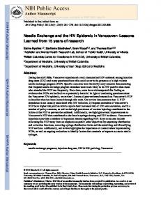
information. Kondratyev distribution radiation Table
by
must
cloudy
et day
be
is
the
spectral
example The
of
spectral
originates
less
very
from
work
in
this
direct sky
the
in
than
composition of
Kondratyev
the of a
in
a
2.3. Sun
energy
and
in
difference solar
case
cloudy
of
that
of
For will
is
a
reason,
used
cloudy
clear
of
the
this be
a
periods
composition
typical
typical
(1969)
the
for
to
the
diffuse
spectral
Table
for
the
presented
that
and
distribution
given
is
irradiance
that
distribution by
of
giving
extra-terrestrial
indicate
cloudy
distribution
spectral
energy
a
showed
spectra
table
for
2.3
spectral
similar
a
radiation;
Table
for
of
energy
the
spectrum
distribution
(1982)
extra-terrestrial
published
solar
from
Analysis al.
has
solar
diffuse
energy
sky.
Bird
the
Results
the
radiation clear
and
2.3.
between
in
(1969)
sky
as day.
also
depicted
in
an
21
3.0
—
2.0
>
co
1.0
CO CD
0.4
0.5
Wavelength
Figure
2.2
Video Curve
Camera
0.6
0.7
0.8
0.9
(.um)
and
Filter
Spectral
Response
22
Table
2.3
Energy D i s t r i b u t i o n i n the Solar Spectrum Outside the Atmosphere ( 1 0 " c a l / c m m i n ) a n d the S p e c t r a l C o m p o s i t i o n o f D i f f u s e R a d i a t i o n (10 c a 1 / c m m i n ) From K o n d r a t y e v (1969). 3
2
6
DX,M
0.28-0.30 0.30-0.32 0.32-0.34 0.34-0.36 0.36-0.38 0.38-0.40 0.42-0.44 0.46-0.48 0.50-0.52 0.56-0.58 0.64-0.66 0.70-0.72 0.78-0.80 0.86-0.88 0.98-1.0
Sun
2.6 1 1 .5 21.8 31.3 35.2 36.0 54.3 62.6 59.7 54.6 48 . 4 42.9 35.3 27. 1 21.0
1 cm of clean a i r 3
4.4 14.4 21.9 23.5 20.8 16.9 17.2 13.7 9.3 4.4 2.8 1 .8 0.8 0.5 0.2
100 d r o p s r = 0 . 1M
0.05 0.27 0.44 0.54 0.51 0.45 0. 52 0.46 0.36 0.25 0.14 0.09 0.05 0.03 0.02
25 d r o p s r= 0 . 5M
0.14 0.78 1 .62 1 .78 3.52 3.78 6.41 7.65 7.35 6.67 5.48 4.29 3.04 2.11 1 .36
2
5
drops r=1/_
1.0 4.6 9.2 12.8 14.6 15.1 23.2 25.6 20.6 14.4 18.6 20.0 18.0 15.8 12.4
23
Fig.
2.3. The
procedure
together and
respond
cloudy
t o determine
spectrally
day i s as
how
(for a certain
between
2) n o r m a l i z e 3) m u l t i p l y
of
each
of
The
final
adjustment
to clear
system
expect
t h e camera
compared
to a clear
Fig. decrease for
O.lOMm
sky and c l o u d y
normalized
value
interval
and determine
between
sky c o n d i t i o n s
of the c l e a r
clear
to respond (between
sky.
the magnitude
the camera's
and cloudy
to a typical
composition
clear
of the c a m e r a / f i l t e r
and cloudy
response
15.7% d i f f e r e n c e
spectral
considered
(clear
curves,
after
i s 1 1 5 0 5 a n d 9941
f o r the overcast and c l e a r
represents a
camera can
t h e two c u r v e s
integration
units)
to a
OMITI
f o r the camera/filter
(relative This
f o r every
the differences
response
filter
area
by t h e c o r r e s p o n d i n g
0 . 40jum- 1 .
4) i n t e g r a t e
waveband)
curves
t o t h e same
the s e n s i t i v i t y
curve
between
and
0 . 38/im- 1 . Oum
the curves
combination
camera
follows:
1) I n t e g r a t e t h e t w o s p e c t r a l sky)
the video
between
sky, r e s p e c t i v e l y . the response
and cloudy
sky.
1.157 t i m e s
0.4(xm-1 . Oum)
The i m p l i c a t i o n s
more
of the
Given
this,
to the typical
o f an o v e r c a s t of t h i s
one
sky as
finding
will
be
i n S e c t i o n 4.2. 2.3 s u g g e s t s
i n t h e amount
locations
away
from
that
forclear
of energy
skies
present
the zenith.
there
i s a
marked
in a particular
However,
waveband
although the
24
210
in
Figure
2.3
S p e c t r a l D i s t r i b u t i o n of D i f f u s e Solar Radiation f o r Clear S k i e s at the (1) Z e n i t h and (2) a t a P o i n t Where t h e Sky Luminance i s M i n i m a l . From Kondratyev (1969)
26
value
of that
corresponding controls
In was
the
this
The
study,
beside
transferred
easily
latter image
the video
and f l o p p y In a
the disks
Any b r i g h t n e s s
abstracted
(on/off
i s derived
i n the sky. button)
saturation
similar
and s t o r e d
on
be
panel
level
monitor
used
fashion,
(Model
images
23AG)
hosted
images
could
f o r viewing
disks.
EVM
convenient
to store
t h e image
the floppy
and
adjusted
II microcomputer
were
from
may
voltage
blackness.
to the framestore
information
the
Front
and p r o v i d e d
An A p p l e disks
or
video
framestore
from
and v i d e o
two c o n t r o l s
an E l e c t r o h o m e
memory.
from
value
point
and viewing.
framestore
framestore
date.
power
so as t o a v o i d
processing
digital
AC
controls.
located
image
The c o u n t
to the r e l a t e d
include
blackness manually
pixel.
could
from
be
at a
also
the
be
later
25
magnitude angle, the
of t h e energy
the d i s t r i b u t i o n
spectrum
wavelengths sensitive spectral and in
that
resides
1.0/im t o d e t e r m i n e
clear
response
The
capable video
'pixels'
can then
front
continuously
Model fast
i s not p a r t i c u l a r i l y was a p p l i e d
changes
tothe
values
at the zenith Thus,
t o changes
between
system
in zenith
in relative
0.4Mm
t o changes
angle.
An
o f 31.22 a n d 30.74
a n d where s k y no v a r i a t i o n i n
i n the spectral
angle
could
be d e t e c t e d .
274D
video
framestore
composition
picture
be a c c e s s e d
i fdesired. panel
in real
'freeze'.
time
A series
levels
(256 g r e y
levels
study,
the count
value
and d i s p l a y i n g
may
be v i e w e d
elements
allows
of 8 switches
of a p i x e l
will
frame o f video
known a s
2 5 6 x 256 t h e image button
facilitates
bits).
unit i s
processed and
and r e l e a s e of t h i s
in total-8
a single
i n t h e image
contains
switch
This
on a s t a n d a r d
by a c o m p u t e r ,
An i m a g e
pushbutton
has a
A / i ) a n d D/A c o n v e r t e r s .
storing,
and the r e s u l t s
Individual
re-displayed,
frame
with
of d i g i t i z i n g ,
monitor.
A
system
Video
memory
memory
which a r e
o f t h e camera
respectively.
azimuth
Framestore
Colorado
solid-state
with
i n the zenith
Video
system
and
The peak of
i n F i g . 2.3 f o r w a v e l e n g t h s
radiance
was m i n i m a l ,
zenith
t h e same.
methodology
resulted
sky d i f f u s e
with
0.45-0.48Mm
the response
of the video
2.2.1.2
between
composition
analysis
t o changes
remains
the camera/filter
depicted
the spectral
may c h a n g e
of energy
The p r e c e d i n g
curves
luminance
due
still
to.
alternative for
spectrum
pixels.
t o be
viewed
results
ina
display
For the purposes
be t e r m e d
of grey of
this
the 'brightness'
27
Chapter
Three
Experimental
3.1
Field
Measurement
Field the
Geography
campus
at
latitude of
work
85
the
surface and
of
of
metres
and
do
primarily required
are
even
built
frame
had
the
out
an of
the
to
although
the
the
considerably
to
surface
an
camera
for
the
easy
3/4
levelled and
and
to
of
It
computer
however.
cloud
regimes
with
access
was
chosen
facilities
i n p o s i t i o n by
galvanized aligned
correct
due
steel
a
plate
tubing.
North-South,
p o s i t i o n i n g of
the
the
1000
system.
held
inch
instruments.
link
imaging was
gravel
(Hay
northwest.
horizon
and
in
local
north
and
local
a
is
approximately
was
tar
area
variability
1979).
a
Columbia
Vancouver's
the
north
local
of
elevation
study
(Hertzman,
video
support
and
west
to
roof
l o c a t i o n i s at
immediately
rise
further
the
British
directional
mountains
affect
on
uplifting
space
of
km.
westerlies
Vancouver
higher
provide
been
for
9
Climatically,
contribute
site
video
frame
West
This
122.96°W
i s roughly
coastal
out
U n i v e r s i t y of
longitude
significantly
storage
by
The
allowed
The and
to
and
carried
Columbia.
mid-latitude
North
roof
and
the
British
site
orographic
The
at
was
exhibit considerable
mountains
through
power
the
not
study
district.
1976).
cities
These
The
winds
Oke,
They
49.74°N
business
zone
this
Vancouver, of
Site
Department
metres.
central
for
Procedures
on
a
This and
occulting
to
28
disk.
When
spirit
level
Fig.
3.1
normal
the
of
table,
the
instrument
be
had
reference
located
and
of
fisheye
frame
was
sequence details
3.1.1
of
Sky
by
on
to
at
a
a
the and
then
focus
on
and
f o r the same
sky
with
in Fig.
camera
a
3.1.
in i t s
the a
was
the
lens.
i n the
1.5
table
camera
sky
was
siting
a
located
on
compass
and
This
metres
actinometer
a
the
plane
the
roof
vent
deemed
to
that The
video
as i t
a was
plane of
the
field-of-view
camera
and
support
actinometric field-of-view
due
to
measurements.
the
a
on
northeast i n the
ensured
served
ensured
measurement.
Likewise,
on
mechanism
and
the
would
placed
system.
and
and
This
a b s t r a c t e d from
target
f o r each
the
i n the
actinometer
way
plane
hemisphere.
point
lens
approximately time
F i g . 3.2
illustrates
the other
set-up.
Factor Analysis
view was
the
the
both
actinometer
experimental
View
levelled
levelled
ensure
local
camera
camera
the
sky
and
brightness value
radiance
(1980),
received
no
never
of
The Steyn
at
as
same
to
the
i n the
camera the
way
When
location
was
frame
was
depicted
previously sighted with
with
positioned table
mean
used
been
in line
a
levelled
was
camera
manner
placed
measured
sky.
i t was
metal
was
the
radiance a
i n the
this
i n such
to
the
position.
viewed
correspond
which
shows
actinometer
radiometer
image
vertically,
aligned
operating
aligned
that
and
also
The was
placed
factor,
as
used
describe
video
to
camera
determined
lens
the
by
the
amount
emanating
methodology of
from
of
radiation a l l sources
29
Figure
3.1
V i e w o f V i d e o Came r a P o s i t i on
Mon i t o r i n g
30
gure
3.2
View Roof
o f F i e l d M e a s u r e m e n t S i t e on of the Geography D e p a r t m e n t ,
the U.B.C.
31
above
the In
local
this
analysis,
photographed clearly. a
so
This
horizontal
be
of
be
radius
video
horizon
as
of
polar a
of
features
was
9.4
image
a
cloudless
could
enlarged to
cm.
This
graph
finite
over
n
x
the
The
25.4
cm.
print
view
annuli
was
identified
20.3
allows
paper.
sum
be
sky
with
areas
factor
(due
to
to
(0 _ ) s
the
n=41 i n t h i s case) as f o l l o w s : n = 1 n E s i n ( - ( i - 1 / 2 ) ) c o s (ir( i - 1 /2 ) ) a • 2 i =1 2n 2n i s the angular width of the i t h annulus (Steyn,
r
size
image,
4> 5
where
a-
Since
the
horizon
image
d i d not
boundaries
preserve
areas
i n each
multiplied view
onto
expressed
the
sky
that
a
photograph
transferred
can
horizon.
the
annulus by
factor
(Steyn,
on
were
an
per
1980).
onto
traced
step-wise
fashion
so
The
angular
extent
of
the
in a
paper.
then
The
as
coordinate lines,
total
determined.
a d j u s t e d view annulus
1980).
f i t exactly
graph
was
(3.1)
factor,
contributed
summation
of
a l l n
If this
the
as
to
was
0./a^,
i t would
give
to
total
by
the
sky
the
sky
view
the
entries
was
factor. Calculations below
the
2.3%.
Thus,
emanated result did
3.2
local
not
horizon
assuming
from
of
this
the
sky
significantly
at
that this
the
97.7%
hemisphere i t was
affect
view
factor
for
experimental site
isotropy,
finding,
Measurement A
indicated
above
of
the
concluded
this
the
total
local
that
was
elements 0.023
radiation
horizon.
the
or
local
As
horizon
study.
Procedure
preliminary
phase
of
field
o b s e r v a t i o n s was
a
carried
out
32
from
July
usually not
to
exceed
affected
such the
29
that
a
September 3 ms~ ,
by
variety
(0/10
data
overcast
sky
provides
a
number
of
during
the
time
on
abstracted
the
sighted and
The
a
of
taken
note
8/10
were were
examined
using
categories: cloud
the
clear
cover);
conditions.
of
and
Table
along
3.1
with
predominate
by
solar
obtain
the
of
this
of
the
the
azimuthal
noon
in order
between
diffuse
video
the
sky
cover
best via
sampling to
those
be
(given
the
of
time
allocated
less
samples
to
areas
the
This
pattern
of
sampling
at
lens
the
of
near
the
the
the
corresponding grid on
of
an
the
sky
video
monitor.
spatial
coverage
where
and
radiance
brightness
based
high
sky
year
was
on
any
pre-determined
sampling
chosen
period
procedures;
points
set
afforded
parts
two
and
r e p r e s e n t a t i o n of
fisheye grid
A
was
angular
the
at
same
establish
synchronous
image
coordinates
to
radiance
and
the
brightness
included
actinometer.
z e n i t h and present
for approximately
hemisphere,
from
The
Sun.
be
observation
measurements
sky
viewed
likely
not
characteristics
broad
to
cloud)
relationship
as
the
three
(1/10
day
and
after
hemisphere
at
each
measurement
values
design
to
10/10
were
i n the
across
to
of
and
points
attempt
sky
did
measurements
conditions could
cloudy
taken,
zenith angle.
zenithal
the
speeds
day.
before
those
sky
and
listing
actinometric
to
actinometric
assigned
(9/10
scans
dependence
of
partly
Measurements of
the and
Wind
technique.
were
cloud);
1983.
turbulence
experimental The
so
1
13,
the
day)
horizon
necessary
and
Sun
would
and opposite
in order
to
33
Table
Date
3.1
Record
of O b s e r v a t i o n
of F i e l d
Observations
Sky
Condition
Number o f Scans
83-08-29
Clear
Sky
1 1
83-08-30
Clear
Sky
9
83-08-31
Partly
83-09-01
Cloudy
Overcast
11 11
83-09-03
Partly
83-09-20
Clear
Sky
9
83-09-21
Clear
Sky
9
83-09-22
Partly
Cloudy
4
83-09-24
Partly
Cloudy
8
83-09-25 83-09-26 83-09-27 83-09-29 83-10-02 83-10-13
Cloudy
.
Overcast Partly
Cloudy
Overcast Partly
Cloudy
Overcast Partly
Cloudy
10
8 1 11 5 4 3
34
represent low
the
values)
full
present
measurements, the
sequence
zenithal with set
a
or
made
each
completed,
zenith
with
levelled of
the
at
the the
zenith
scan so
angle
intensities
sky.
Between
zenith
was
60°
to
30°
angle
changed
intervals
routinely
beginning
and
an
end
and
with
to
the
pattern
zenith at
as to
had
video
70°
and
a
the
30°
was
(to
was
the
azimuthal
actinometer
sky
60°)
carried
monitor,
final
The
was
been
increments
the
one
started
angle
30°,
i n c r e a s e d by
each
to
minimum
observation
sweep
30°
high
confined
on
during
the
a
grid
An
completed.
and
to
constant
again
10°
of
then
entire
clipping
was
before
usually
increments.
was
by
was
angle
azimuth
avoid
kept
The
(from
individual
was
only.
zenith
When
in the
as
movement
direction
position.
the
Then,
radiant the
that
i n c r e a s e d by
another
sweep
such
Keeping
was
at
across
azimuthal
azimuth
out.
was
30°.
of
a c t i n o m e t r i c movement
measurement
at
and
range
scan
and
observation period
was
the
time
was
recorded. A
single
seconds
during
instrument point
actinometric observation which
and
(about
the
20
to
equilibrate.
to
complete.
for
a
sample
present,
the
z e n i t h a l - and
s h u t t e r was
actinometer
seconds) An
Figure grid.
(at both
and
entire 3.3 For
i t s position
actinometer
metal
azimuthal
15
set
seconds took
illustrates
i n the the
was
scan
times
took
when sky
beginning
location
was
to
used a
to
zero
given allow
a
typical
the 18
scan
minutes sequence
was
sighted with
the
end
noted.
of If
a
the
instrument
disk
and
solar
35
sampling
approximately
the
was
at
approximately
scan) the
Sun
and was
its not
35
visible,
a record
theoretical
of observation
determination
times
of i t s
allowed
zenithal
for a
and
azimuthal
position. At being sky
t h e same
taken,
was
camera
obtained
levelled
and t h e p o s i t i o n
sure
there
would
direct order
solar
beam.
to ensure In
order
digitized
image.
the
and s t o r e d
video
of t h i s image.
calculation
The b r i g h t n e s s
point
explanation
i s given
and a z i m u t h a l
combined
with
the in
correct pixel
t h e knowledge field-of-view,
shape
I.
This
corresponding
first
shape
was
could step
on t h e to the
then
to locate the
taken
of the
in this of sky
coordinates
size
of the
f o r the determination field-of-view
appeared
be
in locating
the shape
pixel
of the angular allowed
i t was
transformation
to screen
in
point,
viewed
A
of the actinometric
coordinates.
sampling
plane
the
as p o s s i b l e .
as p o s s i b l e ,
The
t o make
to occult
values
values
each
checked
instantaneous
of the steps
points
of
t o an
to determine
i n Appendix
The
checked
was
were
of the
a l s o monitored
as clean
t h e image
and then
was
disk
was
the actinometer
on
image
points.
as necessary
i n the computer.
image An
disk
This
lens
as close
a video
at the start
the sky hemisphere
zenithal
actinometric
flare.
i t remained
of the sky that
sky sampling
centre
level
of the b r i g h t n e s s
to locate
summed
lens
The f i s h e y e
necessary
portion
spirit
measurements
sampling
of the o c c u l t i n g
to obtain
representation
a
moved a s o f t e n
that
from
f o r t h e same
be no
a n d was
the actinometric
information
with
scan
continually
that
brightness
being was
time
roughly
of
expressed elliptical.
36
Since time,
the
same
i t relatively
program
which
out
the
p o r t i o n of
The
sum
of
computed, region. each
the as
of
the
the
In
order
synchronous
time
was
brightness time
helped
more
enter
the by
the
button
the
pixels
number This
pixels
allowed
representing
to
function
switch-box and
video
was
to
in
image the
to
of
problems
the
real
the
objects
were
and
scanning
clouds)
necessary,
to
to the
computer. was
brightness
image
the
on
recorded sky
c o n d i t i o n s at
This
procedure
the
of
increased
zenith.
azimuthal
coordinates
into
sequence.
at
point.
to
measurement
kept
computer
the
opportunity
was
spot.
necessary
the
the
the
program
the
to
(i.e.
be
of
for
at
time
effects at
the
sampling
the
was
determination
end
allowed
zenithal
(eg.
area
within
could
actual
the
that
sampling
record
words,
'seeing'.
i t was
video
draw
corresponding
button,
and
as
to
that
particular
other
corresponded
was
connected
the
and
for a
which
was
pressed, In
grid
contained
of
every
computer
actinometer
a c t i n o m e t r i c measurements.
program
another
on
followed
a
corresponding
pressing
'refreshed'.
the
of
roof
corresponding
observations
the
values
value
e l i m i n a t e such
Otherwise, start
on
velocity
sampling
the
points.
hand-held
the
that
the
program
values
of
to
angular
gives
freeze
the
point
was
design
a c t i n o m e t r i c measurements)
site
to
information
the
this
measurements
each
number
observation,
triggered
monitor
3.2
with
measurement
Each
the
small,
each
sky
brightness
for
a
the
sampling
mean
design
locate
brightness
was
of
s t r a i g h t f o r w a r d to
would
Table
of
For
sequence
a
scan,
If the
manually the
automatically set
computer. to
37
Table
3.2
Sequence of O b s e r v a t i o n s i n Second Sampling G r i d w i t h C o r r e s p o n d i n g Number o f P i x e l s Zenith Angle (Degrees)
0 30 30 30 30 30 30 60 60 60 60 60 60 60 60 60 60 60 60 70 70 70 70 70 70 70 70 70 70 70 70
Azimuth Angle (Degrees )
0 0 60 1 20 180 240 300 0 30 60 90 120 1 50 180 210 240 270 300 330 0 30 60 90 1 20 1 50 180 210 240 270 300 330
No.
of
195 201 205 205 201 205 205 231 235 237 237 237 235 231 235 237 237 237 235 259 251 253 255 253 251 259 251 253 255 253 251
Pixels
38
Before the
s k y image
level
one would
present
black and
video
of
was
ended,
adjusted
At the completion
a
had changed
loss
then
that
was
could
relationship
between
sky had been phase
be m o d i f i e d
radiance
determined was
launched
areas
scan
t h e most
noted.
the scan,
or blackest
If and
portion study.
of o b s e r v a t i o n had
within the
or improved.
Once t h e
and b r i g h t n e s s a t any p o i n t i n
(see Section with
data
sky c o n d i t i o n s and c a r e f u l
images
t o be s t o r e d
for further
latter
measurements
were
1983; J a n u a r y
were
during
the. p r e l i m i n a r y , e x p l o r a t o r y p h a s e
that
each
v i athe
not included i n the
indicated
and
t h e measurement
digitized
i n the whitest
scan
methodology
December,
out before
was
i n an
(white)
of a sky scan,
substantially
of d e t a i l
This
levels
saturated
once
sky cover
range.
and blackness
carried
was
range) t o
a n d s o i t was
level
procedure
analysis
particular
the grey
both
never
necessary.
(the f u l l
possible
(or minimize)
data
observing
levels
t o view
video
due t o t h e a c t u a l
not always
some
the
were
and i t s b r i g h t n e s s c h a r a c t e r i s t i c s
t h e image, When
However,
necessary
any a p e r t u r e , that
f o r 256 g r e y
s k y r e p r e s e n t a t i o n was
sky cover
there
a n d make
maximize
were
had begun.
i t was
adjustments
was
This
the c o n t r o l s
framestore the
this
to eliminate
sequence
sky scan,
by a d j u s t i n g t h e v i d e o
regions.
recent
wish
t o manually
accomplished attempt
level
i n t h e image.
characteristics necessary
of a
on t h e m o n i t o r
or blackness
Ideally, be
the start
over
and February,
secondary
collection selection
display
obtained
4.1) a
f o c u s s i n g on
of useful
and a n a l y s i s . a a three
1984.
month
Since
sky
These period:
t h e Sun
was
39
much
lower
sampling
The
sampling
grid
and
actual
earlier. were
the
levels.
Figure
any
image
was
not
for
future
of
for a
representation
level
at
a
with
the
the
setting.
radiance the
from
a
scan
time
did
not
seem
to
view
be
archived
provided
transformation
not
sky
be
in a
radiance
a
the to
A
appropriate
spectral
blackness pose
that
scan ( i . e .
would
between
aperture,
video
( i . e . images).
i f the
relationship
the
could
measurements)
maps
or
images
images
dramatically, resulting
current
This
of
sky
of
sequence.
blackness
appropriate
design
s e v e r a l sky
for analysis one
provide
described
condition with
method,
later
changed of
sky
as
scan,
the
the
scanning
variety
brightness
produced
taken
characteristics
and
the
aperture, a
to
indicates
sky
a
year,
continue
of
utilized
of
3.2
provide
determine
number
to
the
obtained
the
this
of
were
particular
With
curve
image
brightness
a
to
end
to
currently
necessary
an
done
as
illustrates
the
brightness
calibration for
3.3
so
time
Table
changing
study.
synchronous
altered
at
wihout
representative
that
observations
However,
This
radiance
was
at
strategy.
field
stored
data
horizon
sequence
optimal this
on
and
problem
poor and video during
this
study.
3.3
Estimation A
simple
probable The
video
where
error
of
experiment
Error was
i n the
Video
System
carried
out
in order
associated with
camera
lighting
the
was
placed
the
use
of
horizontally
conditions could
be
kept
the on
a
to
assess
video
system.
table
in a
constant
and
no
the
room
gure
3.3
Design of Sampling G r i d . the C e n t r e of a S a m p l i n g
Each + Point
Represents
41
external The
disturbances
neutral density
lens
filter
and the r e s u l t i n g
aperture, to
blackness
produce
an
image
representation Twelve
images
This pixel
intensity
scale)
with
a
0.276%. centre
standard operating
± 0.309%.
error
in the video
mean
values
of temporal
area,
(about
These
span of constant.
change i n
error
i n the
the twelve
images
level
was
92.13 for a
( f o r an 8 b i t single
that
201
points
pixel.
pixels),
i n a mean
d e v i a t i o n of
1.9.
standard
deviation expressed
the
brightness
brightness
level
This
was
that the 1.0%.
an
analysis
image of the
o f 93.5 w i t h
a
of v a r i a t i o n (the
as a percentage 2.04%.
±
the
than
within
However,
The c o e f f i c i e n t
was
nearer
of l e s s
about
23308
indicated
brightness
images.
was
the brightness
deviations
t h e mean
includes
taken
i s on t h e o r d e r
f o r a l l twelve
then,
image
the brightness
standard
system
resulted
between
of a d i g i t i z e d
standard
mean
a time
as the probable
f o r sampling
expected
be e q u a l
0 t o 255.
conditions, the actinometric
and f o r t h i s
18518
would
from
over
d e v i a t i o n o f 4.04
a t t h e edge
o f t h e image
was
as well
i n order
complete
conditions held
the extent
camera
( i . e . the
adjusted)
levels
with
brightness
Similarily,
It
were
sequentially
of the changes
t h e mean
pixels,
intensity
minutes,
the fisheye
system.
that
field-of-view
high
of the camera.
was m a n i p u l a t e d
contrast; a
taken
showed
normal
image
from
with
indicated
Investigation
Under
removed
levels
values
video-framestore
was
operation
and v i d e o
fifteen
information
affect
video
of v a r y i n g were
approximately
254
would
o f t h e mean) o f
shows
that
over
the
42
15
minutes
typically the
during only
twelve
3.3.1
which
a
2%
of
slight,
a
sky
but
to
'registration'
magnitude
of
an
of
sum
of
brightness
was
k n o w n ) was
the
misregistration)
of
was
the
it's
with
showed
x
15
square the
4.73%,
as
(8
at
RMS
the
there
was
brightness
levels
This
of
of
of
the
from
about sky,
error
the
and
of
will
referred
1 at
77
sky
4.57%
or
overcast
that
the
the
edge
there
was
a
3.17%
for
the
2.5
of
This
on a
the root
pixel
s i m i l a r RMS overcast
of
The
actinometric
centre)
showed
region
magnitude
square
positions
(the
window
image.
the
the
the
sky
window.
clipping.
with
what
'window'
the
the
at
case
be
images,
video to
windows
darkening
clear
the
apparent
around
Sky
between
central
(the
of
indicated
determine
approximated
approximately
for
A
image
pixels within
edge of
to
and
corresponding
the
the
three
test.
8 positions
computed
Registration
existed
be,
pixels
2.5
exclusion
error
a
would
by
at
p a r t l y cloudy with
on
order
of
in
evidence
(RMS)
In
values
values
the
results
for
in
positions.
p i x e l s which
size
c a r r i e d out The
for
spot
offset
9 positions
which was
15
chosen
brightness
computed
the
c l e a r , p a r t l y cloudy
were
the
point
offset
error.
error
conditions
sampling
stored,
Inherent
sampling
calculated
such
representative
window
between
Error
consistent
true
a
and
the
point's as
were
images.
Location a
images
difference
Assessment of Coordinates
that
the
The in
each
of
was the
image
procedure sky
image.
mean offset;
error sky
sum
of
case.
43
3.3.2
C a l c u l a t i o n of the E r r o r Level Determination The
total
measurement
E E E
c
where
(3.2)
=
0.0473
x X
(3.3)
v
=
0.0317
x X
(3.4)
X
i s the average
overcast
represent
cl,pc
the data
sky c o n d i t i o n s ,
and
overcast
ov
to proceed between
brightness.
This
with
for a
represent
system
had
been
analysis
variables,
will
be
sky
partly
associated i t is
t h e most
radiance
described
cloudy
for clear,
calculated, of
scan
coefficients
the errors
the determination
t h e two
The
as determined Once
manner:
single
clear,
respectively.
skies.
acquisition
relationship
chapter.
and
value
the r e g i s t r a t i o n error
cloudy
possible
brightness
i n the following
value
x X
and
with
brightness
0.0457
the s u b s c r i p t s
calculated
with
=
l
be
associated
Brightness
now
and
partly
error
with
may
pc q
probable
Associated
probable
and
in the
following
44
Chapter
Four
Calibration
4.1
Determination Radiance
4.1.1
diffuse was
a
linear
first
from
recorded
initial were
step,
the
the
be
most
brightness
video the
between
two
the
thorough
data
available
British
defined
as
Columbia's
indicated as
which a
decided
to
the
be
of
carried
out,
relationship
then
during
a
measurement
the
suggested
was
library
Computing
points
normalized
undertake
variables;
actinometric
analyzed a
two
image
v a r i a b l e s and
were
distribution
could
of
so
scan)
sequence.
variable since
linear with
step-wise
brightness,
sky
sky
dependent a
a
radiance
For
the
of
they
radiance were
radiance;
the
variable.
relationship
this
(as
and
observations
r e p r e s e n t a t i o n of
investigation
The
nature
independent
were
analyses
angular
hemisphere
the
same the
the
Preliminary
the
the
i t was
valid
values
of
brightness.
computations, to
Values
sky
define
and
during
chosen
deemed
(TRP)
the
r e g r e s s i o n between
abstracted
between
Analysis
to
radiance a
Relationship
Brightness
over
necessary
As
the
determination
radiance
between
as
and
Regression Before
it
of
Procedure
i n mind,
existed a
more
undertaken. using
a
linear
programme Centre.
e x i s t e d as residual
i n The The
outliers less
regression
than
routine
U n i v e r s i t y of
initial (an -1.96
results
outlier or
is
greater
45
than
1.96
matter
for a
to
probability
exclude
them
from
were
excluded
on
were
found
correspond
to
measurement. the
camera
(eg.
tower)
which
be
than
240
have
been
of
from
from
also
the
The
a
the
values
how Y'
Y
=
was
(Y
195)/Npix
x
the
with
spurious
data
points
than the
a
brightness camera
an
(eg.
radiance or
anemometer It
values
since
that
radiation
recorded.
brightness
the
should
greater
camera
projection
to
or
points
resulting
object
being
simple
saturation,
shortwave latter,
analysis
may
properties
compensate
the
z e n i t h a l - b r i g h t e n i n g and
present
across
an
image.
Eqn.
4.1
accomplished. (4.1) radiance
radiance
of
of
that
of
pixels
representing Y
number
of
pixels
corresponding
a
sampling
same p o i n t ,
(Npix>l95) to
a
Npix
and
sampling
point
195
and
is is
point
Y'
the the
located
at
zenith. In
order
constant
to
slope,
derive in
this
a
strictly
case
1.0,
necessary
to
adjust
the
brightness
aperture,
blackness
and
video
to
These
from
value
number
the
set.
equi-angular
the
diffuse
'compensated'
data
i t necessary
effects
this
represents
the
for
i t was
sighting
the
The
so
invalid
and
i n the
f i s h e y e l e n s made
horizon-darkening shows
an
other
points
included
5%)
working
resulting
affect no
of
being
with
actinometer
saturating.
actinometric
of
smokestack),
that
were
the
something
could
noted
basis
former,
sensing
smoke
perhaps
the
level
note
that
in this
study,
linear and
the
intercept
value
level lens
relationship,
so
as
effects. aperture
of to
It was
0.0)
(i.e. a i t
was
remove is
important
not
46
graduated be
or
calibrated
ascertained
video
level
(b );
the
r
X'= where the
X
together
value
affected level
(a ).
an
adjustment
(X
-
r
i s the
as
to
the
relationship
between
measurements
was
may
be
found
overcast linear
relation
constant
was
acquisition
phase
digital
values
linear
the
relationship predict
of
II.
these a
regression
influenced
line
the
brightness
by
was
of
between from
the
Eqn.
4.2
undertaken.
the
two
In
more.
should
between
(recall there
words, the
was
to
brightness
42
and a
(i.e.
two
in the from
data
the to
camera
the has
non-linearities.
determine in order
value,
of
curves
confirmed
the
no
brightness
the
Indeed
camera,
that
were
been
cloudy
the
the
brightness
4.3.
a l l 'links'
reaching
to
regression
and
is
curve.
results
for partly 4.2
X'
Due
if
and
the
and
have
zero
actual
other
exercise
given
once
v a r i a b l e s was
since
and
point
regression
line
in Tables
energy
radiance
the
presents
Results
linear.
this
sampling
measurements
of
framestore
a
a of
4.1
characteristics)
radiance
and
c o r r e c t the
relationship
expected
radiant
aim
hand,
could
aperture
the
approximately
Table
given
were
i n the
transfer
Since
be
system
initial
are
Such
to
of
examples
between
slope).
parameters
slope
actinometric
while
scans
the
of
regressed
intercept
i n Appendix
sky
for
value
were
linear.
scans
other to
value
data
close
sky
slope
described
brightness
m o d i f i c a t i o n s , the
clear
that
a l l that
(4.2)
above
and
the
Hence,
r
transformed
1.0
was
the
order
brightness
'compensated' The
on
In
r
a )/b
manner.
observations
blackness
intercept values,
from
i n any
the to
radiance
should
47
Table
4.1
Regression Results f o r Clear Skies using C o r r e c t e d B r i g h t n e s s and Radiance V a l u e s (Wm" sr" ) 2
Scan
JD210.1 JD210.2 JD210.3 JD210.4 JD210.5 JD210.6 JD210.7 JD210.8 JD210.9 JD210.10 JD211.1 JD211.2 JD211.3 JD211.4 JD211.5 JD211.6 JD211.7 JD211.8 JD211.9 JD212.1 JD212.2 JD212.3 JD212.4 JD212.5 JD212.6 JD212.7 JD212.8 JD212.9 JD232.1 JD232.2 JD232.3 JD232.4 JD232.5 JD232.6 JD232.7 JD232.8 JD233.1 JD233.2 JD233.3 JD233.4 JD233.5 JD233.6
N
27 27 28 28 29 30 31 31 27 26 28 30 26 30 30 29 30 28 26 28 29 25 25 30 29 27 31 28 29 28 27 31 28 29 30 26 27 31 28 29 28 28
1
a
b
r
0.66x10" -0.73x10" -0.35x10" -0.58x10" -0.11x10" -0.85x10" -0.25x10" -0.31x10" 1 .054 2.731 -1.186 0.24x10" -0.302 0.47x10" -0.84x10" -0.55x10" 0.24x10" 1 .006 1 .004 -0.967 -1.952 3.476 0.551 -0.42x10" -11.37 -4.938 -0.33x10" 1 .091 0.243 0.360 2.479 -0.95x10" 0.853 -1 .455 -0.26x10" 1 .671 -0.616 0.35x10 -0.112 -0.990 -0.976 0.835
5 4 4 5 4 5 4 5
4
5 5 4 4
4
4
5
4
4
r
r
1 .00 1 .00 1 .00 1 .00 1 .00 1 .00 1 .00 1 .00 0.93 0.97 1 .03 1 .00 0.98 1 .00 1 .00 1 .00 1 .00 0.99 0.98 1.01 1 .02 0.89 0.98 1 .00 1 .40 1.16 1 .00 0.99 1 .01 1 .01 0.98 1 .00 0.99 1 .09 1 .00 0.98 1 .01 1 .00 0.97 1 .06 1 .06 0.99
St. E r r of b r
r
2
0.057 0.925 0.065 0.895 0.084 0.845 0.072 0.881 0. 108 0.760 0.727 0.116 0.097 0.787 0.111 0.736 0.063 0.899 0.053 0.932 0.078 0.869 0.071 0.878 0.072 0.884 0.647 0. 139 0. 126 0.694 0.099 0.791 0.077 0.858 0.056 0.923 0.977 0.031 0.032 0.976 0.085 0.843 0.088 0.813 0.119 0.747 0. 108 0.756 0. 128 0.817 0.887 0.083 0.085 0.826 0.049 0.940 0.044 0.951 0.917 0.059 0.060 0.915 0. 100 0.774 0.085 0.838 0.074 0.889 0.071 0.877 0.045 0.951 0.047 0.949 0.043 0.950 0.680 0.886 0.921 0.060 0.053 0.940 0.064 0.901
St. E r r of Y 5.65 1 0.95 1 1 .66 9.53 1 4.57 1 4.20 16.41 16.87 8.82 9.84 7.12 8.14 6.81 1 6.99 1 2.60 14.95 8.97 7.51 4.75 4.90 17.98 10.71 1 0.85 1 3.45 1 3.29 9.57 1 3.76 9.55 8.14 6.92 8.58 1 6.80 6.49 7.24 11.31 5.20 4.96 5.97 9.25 5.25 4.86 7.31
48
Table
4.2
R e g r e s s i o n R e s u l t s f o r O v e r c a s t Sky Data C o r r e c t e d B r i g h t n e s s and Radiance V a l u e s (Wm" sr ) 2
Scan
JD245.3 JD239.1 JD239b.1 JD239d.1 JD239f.1 JD239f.2 JD237.1 JD237.2 JD237.3 JD213.3 JD213.4 JD213.5 JD213.6 JD213.7
N
29 28 29 25 31 26 30 27 26 29 30 29 29 31
Using
_ 1
a
b
r
2. 898 - 0 . 401 - 3 . 278 1 .407 0. 4 2 x 1 0 " ' 2. 480 -0. 11x10" 0. 890 - o . 926 - 4 . 996 - o . 40x1O " 4. 091 3. 427 0. 1 5 x 1 0 ~ * 5
-
r
0 .955 0 .979 0 .971 0 .968 1 .00 0 .975 1 .00 0 .975 1 .009 1 .030 1 .00 0 .962 0 .977 1 .00
Stand. of
Err b
r 2
r
0. 0805 0. 461 0. 1 20 0. 056 0. 108 0. 041 0. 042 0. 034 0. 045 0. 1 22 0. 098 0. 068 0. 1 34 0. 084
0 0 0 0 0 0 0 0 0 0 0 0 0 0
.839 .946 .709 .929 . 746 .959 .954 .971 .955 .727 .789 .880 .663 .829
S t a n d . E: of Y
2 3 . 84 6. 46 7 0 . 06 9. 54 3 9 . 71 9. 72 1 .88 3. 45 9. 1 4 28. 1 6 15. 1 4 1 1 .43 19. 21 2 0 . 23
49
Table
4.3
Regression Results f o r P a r t l y Cloudy Skies C o r r e c t e d B r i g h t n e s s and Radiance Values (Wm" sr" ) 2
Scan
JD2 41.2 JD241.3 JD241.4 JD239.7 JD238.2 JD238.3 JD238.4 JD237.4 JD237.5 JD237.6 JD237.7 J D 2 3 7 .8 JD236.4 JD236.5 JD236.6 JD236.7 JD234.2 JD234.3 JD234.4 JD215.1 JD215.4 JD215.5 JD21 5.6 JD21 5.7
N
28 31 27 27 29 28 29 27 29 29 29 29 31 27 26 29 28 27 27 30 27 30 29 28
using
1
r
1 .708 -0.55x10" 5 -3.393 -0.224 0.52x10" 4 -0.835 0.32x10" a -4.018 0.46x10" 4 -0.28x10" 4 -0.70x10" 4 -3.183 -0.70x10" 4 1 .401 1 .609 0.970 -0.901 1 .302 -5.831 0.20x10 4 1 .547 0.46x10" 5 1 . 452 1 .405
b
r
0 .935 1 .00 1 .083 1 .005 1 .00 1 .010 1 .00 1 . 1 46 1 .00 1 .00 1 .00 1 .02 1 .00 0 .975 0 .970 0 .920 0 .994 0 .985 1 .062 1 .00 0 .980 1 .00 0 .982 0 .984
St. E r r of b
r
0. 103 0.101 0.046 0.052 0.086 0.047 0.061 0.097 0.063 0.046 0.059 0.087 0.079 0.040 0.042 0.098 0.067 0.044 0.062 0.084 0.096 0.112 0.072 0.059
0.761 0.770 0.956 0.937 0.834 0.946 0.908 0.848 0.902 0.945 0.915 0.833 0.846 0.960 0.957 0.767 0.896 0.953 0.921 0.834 0.808 0.739 0.875 0.914
2
r
St. of
E Y
27.23 36.53 1 1 .64 11.22 28.91 6.37 1 1 . 63 14.13 13.53 7.97 1 1 . 58 24.04 21 .22 1 2.37 5.58 1 4.59 1 5.23 7.42 1 3.68 11.91 10.55 1 7.78 1 1 .60 1 0.02
50
be
analyzed
however,
as
may
parameters
not
of
universally a
related
employed
dependent
close that
achieve
technique and
1.0
such
for
line an
i t has and
reason
been
used
data
that
should the
be
estimated.
coefficent
of
determination
between
the
becomes
Mark
and
any
less
Church
functional
insignificant;
In
be
latter
most
may
cases
Instead,
in both
the
the
almost
analysis,
incorporate errors so
of
1977).
for choosing
variable
analysis
estimate
Church,
functional
these
analysis
unbiased
(Mark
The
independent
and
best
Regression
the
probable most
(r ) 2
of was
(1977)
suggest
relationship
this
however,
the
and
does
the
not
useful.
Functional Analysis Once
existed
i t had
been
between
analysis
to
error
defined,
ascertained that
radiance
determine
straightforward. the
this
i s to
difference
regression
the
tool,
the
variable.
although
i t s place.
analyses,
to
4.1.2
curve
u n d e r l y i n g the
the
make
provide
statistical
analytical
present
dependent
the
to
in
relation
the
In
the
N
type
curve
of
and
was
analysis,
variables
t o Mark
linear
b r i g h t n e s s , the
actual
this
v a r i a n c e s of according
and
a
relationship
use
of
relatively information
is required.
Church
functional
(1977),
These
about may
be
as
m E
2
=
x
where
X^
replicate
L j=1
(x..
i s the
1
D
-X.) /m
i=1,...,N
2
(4.3)
1
mean
value
observations
of
of x.
x^ and
and
x^
i s the
similarily
j t h of
for E
2
.
m
51
When
the
that
E
apply
and and
2 x
equally
variance
X
In
(X)
= E
this
with
E^
2 y
to
/E
From Y
=
f
i t may
normally and
the
be
assumed
distributed
ratio
of
and
the
error
as
(4.4)
2 x
of
E
2 x
calculated
were
2
the
for
parameter
coefficient
b^
of
relative
brightness each
was
and
point
r e g r e s s i o n a n a l y s i s had
slope
i n the
the
values
scan.
performed,
calculated
determination
analysis) values
radiance in
been
errors associated
as
a
functional
using
b_. a n d
r
derived
from
the
f o l l o w i n g manner,
(the
2
(Mark
and
(1977))
=
((b
this a^
written
determination
regression
b
be
E^
and
distributed
independently
and
Since
Church,
normally
a l l observations
may
respectively,
analysis
are
2
study,
the
slope
are
+
2 r
/r -X)+(((b_ /r -X) +4Xb 2
slope b^X
brightness Therefore
2
value,
where
values to
brightness,
X
a
linear
2
intercept
represents
and
predict
an
2
Y
i s the
radiance
the
2 r
a^
))/2b )
was
known
predicted at
any
transformation
.
2
r
(4.5)
determined.
Thus
(uncorrected) radiance
point using
in a^
(Wm~ sr~ ). 2
the and
sky b^
1
from was
applied. To clear,
verify overcast
Regression
this and
procedure, partly
analysis using
sample
cloudy every
sets
of
data
sky
conditions
fourth
sampling
representing
were point
chosen. of
the
52
entire
sequence
values
were
set
of
the
radiances
were
allowing
the
In
4.4
shows
data.
The
condition.
sky
Wm~ sr 2
have
_ 1
RMS
clear,
in
indicate a 95%
the
values
of The
22%
associated
Section
2.1.3.2,
they
These
include
(i.e. larger
with
a l l regions
errors
than
regression
had
the
the
may or
and
be of
in
Sun) A
follows.
each
and
large
errors
somewhat sky
more
each
that
in 9
conditions Wm" sr 2
which, for
as
misleading,
indicates
_ 1
),
largely
measured
however,
Some
as
portions
correspond
that
to
discussed
small
to
the
detailed verification
This
r
sky
i s due
likely
of
performing
hemisphere.
more
Table
cloudy
value
(13
errors
voltmeter
are
(RMS).
was
31%
data
was
partly
for
of
predicted
(r)
notice
and
the
same
approximately
these
HP
the
the
p a r t l y cloudy
1
of
in
of
advantage
error
analysis
2
predicted
assuming
square
One
2
the
others.
procedure
the
variables
Wm~ sr" )
results
near
in and
r
a
rest
limit)
the
overcast (20
for
the
overcast
i s 40%
f i g u r e s may
locations
calibration
RMS
magnitude
error
fluxes.
that
and
For
c o n s i s t e n t l y high
covers.
mean
Similarily,
mean
confidence
suggests
a l l sky
case
allowing
correlation coefficient
for
the
two
and
c o r r e l a t i o n between
results
respectively. the
the
root
for
.
the
the
at
method
c a r r i e d out
between
a
results,
applied
as
This
similarily
be
determine
results
(significant
clear
to
performed
included
This
well
the
not
calculated. to
was
parameters.
was
values,
as
scan
transformation
order
calculated
b^
a
these
points
existed
measured
in
from
and
analysis
relationship
and
a^
( i . e . those
analysis)
set.
points
abstracted
determination data
of
the
of
to the
53
Table
4.4
R e s u l t s o f F u n c t i o n a l A n a l y s i s t o Show V a r i a t i o n Between P r e d i c t e d and Measured R a d i a n c e s f o r Clear, O v e r c a s t and P a r t l y C l o u d y Sky Conditions
Scan
N
r
2
RMS (Wm" sr~ 2
Clear
)
RMS (%)
Sky 211.1 211.2 211.3 211.4 211.5 211.6 211.7 211.8 211.9
Overcast
28 30 26 30 30 29 30 28 26
0.918 0.937 0.921 0.805 0.833 0.926 0.953 0.978 0.978
6.769 8.107 9.026 13.805 13.459 8.031 8.851 6.328 6.328
31.10 33.00 38.90 54.98 54.53 59.03 31.07 34.32 23.60
25 31 26 29 30 29 29 31
0.923 0.862 0.954 0.805 0.901 0.931 0.761 0.909
13.150 38.340 15.090 29.530 13.190 12.310 17.320 19.210
14.57 39.96 17.01 30.30 17.12 15.16 21.71 18.99
0.944 0.897 0.951 0.974 0.952
11.430 15.710 13.650 8.800 13.800
26.76 38.39 28.96 25.07 36.54
Sky 239.1 239.2 239.3 213.3 213.4 213.5 213.6 213.7
Partly
1
Cloudy 237.4 237.5 237.6 237.7 237.8
Sky 27 29 29 29 29
54
magnitude varies
4.2.
of
across
error
the
sky
Verification This
curve
for
typical
validity the
in
the
using
the
point
in
the
the
results
prediction
Calibration
included
the
b
and
and
were
cloudy
overcast
manner
detailed
of
set
data
so
and
above
separate
be
and
to
radiances.
for
clear,
The
observed
partly and
corresponding case,
a
were
latter
set
group
data
In
order
to
cloudy
of
each
high
this
were
and
pair
of
between
and
used
on
the
4.7
values
show
conditions, with are
the
b^
to values
respectively.
the
residuals
presented.
(r>0.90)
p r e d i c t e d and
data
regression
a^
and
coefficient
remaining
of
4.6
observations
the
the
brightness
along
second
developmental
the
overcast
accomplish
every
from
then
included
( i . e . the
values
correlation
relationship
data
From
predicted radiances
to
on
calculation
4.5,
sky
those
i n the
Tables
calibration
from
abstracted
transform
a
assessing i t s
performed
assembled.
utilized
data
was
this
values
2
These
independent predicted
r
radiance
Procedure of
partly
could
of
derivation
clear,
set
data
parameters.
strong
the
regression analysis
observations)
each
i n the
regression/functionalanalysis.
this,
set,
a
inherent
hemisphere.
of
analysis
conditions
in
the
In
suggests
a
measured
radiances. Variations predicted
and
illustrated of
by
contouring,
i n the
magnitude
of
measured
radiances
across
the
maps o f
these
are
Figs.
produced
the
4.1, from
differences the
4.2 a
sampling
and grid
4.3. of
between grid For
64x64
are purposes
pixels.
55
Table
4.5
R e s u l t s of Transformation from Brightness to Radiance ( W m ^ s r ) f o r a C l e a r Sky, 1356 L A T D e c e m b e r 2 0 , 1 9 8 3 . - 1
z
X
r') 0.0 30.00 30.00 30.00 60.00 60.00 60.00 60.00
6 0 . OO 60.00 70.00 70.00 70.00 70.00 30.OO 30.00 30.00
6o!oo 60.00 60.00 60.OO 60.00 60.00 70.00 70. 00 7 0 . OO 70.00
0 .0 .CO 180 .CO 3C0 .00 30 .00 90 .00 150 . 0 0 2 10 . 0 0 270 .00 330 .00 30 .00 150 . 0 0 2 10 . 0 0 330 .00 0 .0 120 .00 240 .00 0 .0 60 .00 120 . 0 0 180 . 0 0 2 4 0 .oo 3C0 .00 60 .00 120 . 0 0 160 .CO 300 .00
60
13 17 12 15 92 15 13 13 15 30 15 1 15 14 37 20 13 15 79 32 13 15 13 15 43 13
. 80 .JO .92 .85 . 16 .00 .78 .89 . 43 .27 .42 . 28 . 93 .46 .53 .74 . 17 . 83 .84 . 78 . 84 . 34 . 79 . 15 . 43 . 13 1IG . 9 G
4
Y
Y
(Win" ! s r - ' ; )
( W m " :: s r " • )
7 .04 13 . 5 - ! 4 .39 9 .03 79 . 8 0 1 1. 6 3 9 .73 1 1. 6 8 9 . 69 29 . 2 0 130 . 58 12 . 8 7 14 . 7 1 3G . 7 8 17 . 5 5 9 .03 6 .77 8 0 . 14 28 . 6 0 13 . 3 5 9 .77 9 . 53 13 . 3 5 36 .07 12 . 6 3 . 10 . 43 1
10. 75 14 . 0 2 9 . 95 12 . 6 1 8 1 . 86 1 1 .8 4 10. 73 10. 83 12 . 2 7 25. 70 135 . 64 12 . 0 9 1 1 .8 2 32 . 22 16 . 8 6 10. 69 99 1 7 0 . 67 28 . 03 10. 73 12 . 6 0 10. 33 12 . 5 5 3 7-. 3 3 10 . 4 7 1 1 .0 5 13 . 6 2
14 4
1.
Y-Y 'sr
3 .71 0 . 48 5 . 55 3 . 53 2 . 05 0. 1 . 02 0 - 0 . 85 2 . 53 - 3 . SO S . OS - o . 78 - 2 . 89 -4 . 55 - 0 . 69 65 5 .22 - 9 . 47 - o . 57 -2 . 62 2 . 83 0. 80 - 0 . 80 1 . 3 - 2 16 -3 . 05 - 0 . G 1.
1
1.
1
56
Table
4.6
R e s u l t s of T r a n s f o r m a t i o n f r o m B r i g h t n e s s to Radiance (Wm" sr"') f o r a P a r t l y C l o u d y S k y , 1246 LAT D e c e m b e r 5, 1983. 2
Z
0
°)
(°)
0 30, 30, 30, 60, 60 60 60 60 60, 70. 70, 70. 70. 70, 30. 30. 30. GO, 60. 60. GO. 60. 70. 70. 70. 70.
.0 .00 .00 .00 .00 .00 .OO .OO .00 .00 .00 .00 .00 .00 .00 .00 .00 .00 .00 .00 ,00 ,00 OO ,00 00 00 GO
0 .0 60 .00 t o o .00 300 .00 30 .00 90 .00 150 . 0 0 2 10 . 0 0 270 .00 330, .00 30, .00 150, .00 2 1 0 ., 0 0 270, ,00 330, .00 0, .0 120, .00 240, .00 60, .00 120, .00 180, .00 240. .00 300, .00 120. .00 180. 00 2-10. . 0 0 300. 00
X
Y >m"*sr " ' )
6 5 . SO 64 . 7 8 45 . 55 9 1 .02 109 . 4 7 49 . 0 3 4 1 .7 1 48 . 57 7G . 22 118 . 5 0 1 10 . 6 7 45 . 53 5 5 ,. 5 1 7 8 ,. 3 0 12 1 . 7 4 101 . 7 2 58 . 74 6 5 , . 19 76 .02 40, .09 3 9 ,. 8 4 5 5 ,. 6 5 73 .9 1 3 5 , . 76 4 1 .,5 6 5 4 ,, 2 9 7 5 ,, 2 9
3 1 . 14 3 1 . 90 16 . 27 45 . 58 6 9 . 57 23 . 65 15 . 9 0 13 . 9 1 29 . 57 73 . 55 76 . 3 1 16 . 7 5 18 . 6 1 25 . 65 76 . 3 1 67 . 4 0 27 . 35 22 . 79 49 . 28 13 . 8 0 14 . 16 2 1 . 68 27 . 6 0 12 . 9 2 18 . 0 4 20. 3 1 2 9 . 54
Y -Y
Y (Wm~ 3 1 30 12 55 73 15 8 15 4 1 8 1 74 12 2 1 43 84 65 24 30 4 1 6 6 2 1 39 2 8 20 40
:
sr' )
. G4 .49 . 11 . 58 .22 . 44 .44 .OO .43 .85 .37 .09 . 63 .90 . 95 . 8 1 .72 . 89 . 24 . 89 .65 .77 . 22 .75 .30 .47 . 54
1
(Wn" 0 . 50
- 1 . 4 1
- 4 . 16 10. 00 3 . 65 -8 . 2 1 -7 . 46 1 . 09 1 1 . 86 8 . 30 - 1 . 94 - 4 . 66 3 . 02 18 . 2 5 8 . 64 - 1 . 59 -2 . 63 8 . 10 -8 . 04 -6 . 9 1 -7 . 5 1 0 . 09 1 1 . 62 - 1 0 . 17 - 9 . 74 0 . 16 1 1 .00
57
Table
4.7
R e s u l t s of T r a n s f o r m a t i o n from Brightness t o R a d i a n c e ( W m " s r ) f o r an O v e r c a s t Sky, 1033 L A T J a n u a r y 2 0 , 1 9 8 4 . 2
z (°) 0.0 3O.00 30.00 30.00 60.00 60.00 60.00 60.00 60.00 60.00 70.00 70.00 70.00
Y
Y
X
sr"')
D 0 .0 60 180 300 30 90 150 2 10 270 330 30 2 10 330
- 1
.00 .00 .00 .00 .00 .00 .00 .00 .00 .00 .00 .00
204 . 180. 176. 179. 123 . 15 1 . 144 .
19 86 77
82 99 66 37 12 1 . 9 3 108 . 23 125 . 40 111. 77 1 15. 27 103 . 98
2 8 . 17 24 . 82 19 . 7 4 24 . 8 2 15. 57 2 1 . 32 17 . 5 2 17 . 5 2 17 . 4 5 17 . 5 2 14 . 7 1 14 . 7 1 12 . 8 7
(Wm ' s r " ' ) _
25 23 22 23 16 19 18 16 14 16 15 15 14
. 93 .20 .72 .08 . 54 . 78 . 93 .3 1 .70 . 71 . 1 1 . 52 . 20
Y-Y 1
(WnT s r -2 .24 - 1 .62 2 . 98 -1.74 0.97 - 1 .54 1.41 -1.21 -2.75 -0.8 1 0.40 0.8 1 1 .33
58
Figure
4.1
C o n t o u r P l o t of D i f f e r e n c e s Between M e a s u r e d and P r e d i c t e d R a d i a n c e s ( W m ~ s r ~ ) f o r a C l e a r S k y , 1356 LAT December 20, 1 9 8 3 2
1
59
For one
the clear
can see that
sky case,
there
of p r e d i c t e d
solar
This
Wm
_ 2
sr"
likely the
or about
1
region.
would
the
camera
region
o f minimum
about
as
a darker,
respond
2
more
to this
spectral
radiance
there
Portions
1
values
differences
between
with
accuracy
of 8
a n d i s most
energy
results.
intensity,
T h e human
in this
extreme,
approximately
This
eye senses
this
region
but as i t represents the would not
t o t h e same
since
extent
the isolines
correspond
10 w m ~ s r " , 2
often
1
i s due m a i n l y
do n o t e x t e n d
to
radiances
observed
ranging
to the absolute
t o measure
and video
o f 1-2
have
such
c a n b e a s l o w a s 3% w h i c h
of the actinometer
as the
At z e n i t h
t o be an u n d e r p r e d i c t i o n
t h e HP v o l t m e t e r
t h e RMS
9 0 ° away
of overprediction
an o v e r p r e d i c t i o n r e s u l t s .
than
but
spectral
The o t h e r
t o an a r e a
composition
edge
near t h e
of the actinometer,
to radiation
of
i n that
wavelengths
p r e d i c t e d and measured
using
Otherwise
value)
1971) t h e a c t i n o m e t e r
appears
of l e s s
of the
i s on t h e o r d e r
to radiant
of t h e sky which
30% and 50%.
associated fluxes.
area,
of 70° ( t h e outer
Wm~ sr~ .
between
(or 4%).
(Ghazi,
i n the region
at shorter
corresponds
blue
region of
i n response
radiant
and hence,
the horizon) 2
1
minimum
camera
angles
disk,
5 Wm~ sr~
scattering
the
scattering
a n d s o an u n d e r p r e d i c t i o n
the solar
video
camera
an i n c r e a s e
on December 20, 1983,
of the d i f f e r e n c e s i n response
i s not as s e n s i t i v e
of
to
and video
cause
region
from
underprediction
12% ( o f t h e m e a s u r e d
The i n t e n s e
Sun
the
radiances
t o be a m a n i f e s t a t i o n
actinometer
taken
i s a noticeable
underestimation aureole.
a scan
system.
error
small
i s within
60
The
partly
interpret; high the
image.
portions;
certain upper
half
lower
half,
variations
The
angle
isolines
i n the lower ranging
f o rthe highly
i s an e q u a l l y
atmospheric
phenomena
that
this
instrumentation Fig.
4.3
condition. low
contrast
differences this low
plot
i s a very
image; between
this
small
the
those i n of the
and 300°.
indicate 1
A
possible
estimation
arrangement of clouds
of observation. of values
i s related to
representing range
or
I ti s
shows a s i m i l a r
i s manifested
with
in
at a
o f 240°
2
pattern.
an overcast
of radiances
sky
in this
i n the smaller
and measured
to the previous
of contours
half)
by t h e v a l u e
t o -9 W m ~ s r ~ .
case
map
predicted
as compared
gradation
no o t h e r
than
d i s t r i b u t i o n of
a t the time
of a
I t i s not
radiances
angles
systematic
i s the contour
There
-1
configuration
since
gradient
o f t h e image
systematic
differences
unlikely
from
scan,
two m a j o r
The c o n t o u r s
and measured
half
t o have
half).
strongly
o f 30° and a z i m u t h a l
underpredictions reason
predicted
to this
( t h e upper
( t h e lower
and a r e i n f l u e n c e d
between
appears
a steeper
a t t h e t o pof
i t i s a function
phenomenon.
have
as
overprediction.
to overprediction
this
o f t h e image
that
plot
to underprediction underlies
value)
forthis
suggest
easy t o
of o v e r p r e d i c t i o n ,
corresponding
reason
The c o n t o u r
one c o r r e s p o n d s
what
zenithal
contours
point.
the other
region
o f t h e image
an o b v i o u s
the steep
data
( F i g . 4.2) i s l e s s
(71% of t h e measured
1
Analysis
not provide
single
sky r e s u l t
i s a prominant
2
However,
the
there
a s 18 W m ~ s r ~
does
and
cloudy
radiances
two p l o t s .
no d i f f e r e n c e
found
There
between
on
i sa
predicted
61
Figure
4.2
C o n t o u r P l o t of D i f f e r e n c e s Between Measured and P r e d i c t e d Radiances (Wm" sr" ) f o r a P a r t l y Cloudy S k y , 1246 L A T , D e c e m b e r 5, 1983 2
1
62
E
W
Figure
4.3
C o n t o u r P l o t of D i f f e r e n c e s Between Measured and P r e d i c t e d Radiances ( W m " s r " ' ) f o r an O v e r c a s t S k y , 1320 L A T J a n u a r y 2 0 , 1984 2
63
and of
measured
underprediction
the of Wm
radiances
_ 2
sr~
2
associated cloud the
which
those
scatter
actinometer
(greater
a shift
This
contour
variations
plots
over
spectrum
a s k y image. radiance
low
a s s o c i a t e d with
radiances
camera
4.3
Validity A
typical
described judge
utilized
of Approach measurement
i n Section
i fa grid at least
a manner
that
t o t h e camera result
how
2.2.1.1. the value
of the
radiances are methodology i s
5% a t b e s t ,
o f 50% o r g r e a t e r
the d i g i t a l
thick
voltmeter
varying
response
b u t may
also
due t o t h e f o r measuring of the
to the actinometer.
3.2.
the appropriateness
ascertain
skies.
using
or
wavelengths).
The c a l i b r a t i o n
and the s p e c t r a l l y ,
as compared
dense
t o longer
Most
be
droplets could
within
value) at
of about 1
relative
to illustrate
area
of the sky.
the findings of Section serve
An
1
i n such
response
of water
result, in over/underpredictions error
radiation
p r e d i c t e d and measured
of predicting
sr~ .
( 8 % of t h e measured
1
of e s p e c i a l l y
less
effects
with
between
distributed capable
show
i n the energy
i s i n keeping The
patches
would
- 2
of o v e r p r e d i c t i o n could
or r e f l e c t
scattering
3 Wm
t o an u n d e r p r e d i c t i o n
The r e g i o n s
with
than
to the brightest part
corresponds
(5%).
1
greater
by 2 W m ~ s r ~
zenith corresponds t h e image
in
being
using scan
Partial included
Various of t h i s
containing
i n the steady
tests
Scan
31 s a m p l i n g were
sampling
fewer
Data
performed t o
grid
sampling
points as
and t o
points
could
state c o n d i t i o n s of c l e a r
be
64
On
December
points
on
end
the
of
the
20,1983,
sky
scan,
was an
image
the
regression line
gives
the
pertinent
is
the
significant
to
error
a
the
of
Y,
of
the
measure
Table
error
4.8,
of
the
evidence
curve.
These
points. using
only
previous 99%
every
results
level)
only
13
was
data
correlation
so
error
the
standard
errors
in
order
have
results
points (r )
very
2
level),
about
which
2%,
r
f i t of
been
so
when
favourable i t i s not
still
results
as
can
b
the
data
and
are
r
set. 2
of
Y
of
by
has a
r
the
and
b
case.
These
nearly
steady
number
valid
of
r
are
still
results state
seem
predictive
predicted
sampling out,
this
time
the at
the
that incorporating positive and
brightness
in Table
slightly
to
minimal;
r
to
radiative
sampling
low,
Because
results
increased only
very
(significant
strong
JD354b
the from
the
62
from
noted
both
carried
surprising in a
only
standard
be
to
using
r
Not (and
the
a c t i n o m e t r i c measurements
minimal
retain
in the
the
is within
and
obtained
4.8
predicted values
Also, a
the
4.4
Table
of
62
At
Fig.
high
but
at
31.
(JD354a).
of
of
usual
while
departure
close
evidenced
in this
to
the
errors
high,
between
a
data
actinometer.
the
were
standard
only
the
data
The
exist,
on
set
fourth point
points
sky,
data
the
radiance
analysis.
was
as
clear
62
for
regression analysis
measurements
increased
this
i s only
results
Another
for
confidence of
the
of
stored
the
standard
further
was
determination
99%
regression line,
relative
a
for
the
i n s t e a d of
information
analysis
coefficient
c l o u d l e s s day,
measured
shows
regression
a
points
2
suggest
4.8.
2.5%
and
has that
for
conditions need
capabilities.
be
taken
I t must
be
65
Br i g h t n e s s
*Note
Figure
- 4-, 2 r e p r e s e n t po i n t s
4.4
t h e number
and
location
R e s u l t s of R e g r e s s i n g Brightness Radiance (Wm~ sr ) f o r a Clear Sky, 1356 L A T D e c e m b e r 2 0 , 1983 2
_ 1
of
and
data
66
Table
Scan
4 .8
a
Regression
r
b_.
Results
St .
Error
o f a_.
for
Clear
St.
Error
of
b
r
and
P a r t l y Cloudy
St. of
Error
r
2
Sky
N
Y
JD354a
-1 .77
0.907
0.592
0 .014
3.324
0.989
62
JD354b
-2 .62
0.912
0.371
0 .022
3.866
0.994
1 3
JD339
-26 .87
0.891
2.374
0 .031
7. 198
0.941
62
JD339a
-27 .33
0.904
2.866
0 .036
6. 1 93
0.963
31
JD339b
-30 .18
0.961
3.756
0 .042
7.351
0.977
1 3
67
noted
however
sampling
that
point
regions
brightest
region
of
the
curve
of
from
i n the
more
when
only
partial
that
those The
example
data
same
are
on
the are
In
and
value,
this
namely
Part
response
of
of
the
actinometer, cloud
of
case,
parameter
case.
of
as
not
been
full
resulted.
set
cloudy
i s used,
carried
area
the
set
This
for a
based
62
data
points
one
can
99%
see
the in
f o r JD339.
increased
the
The
slightly
greater
scatter
former
viewed
as
sky.
cloudy
F i g . 4.5
sky
shows
Table
of
4.8 r
2
scatter
standard error
than
was
partly
ensure
level).
larger
larger
to
i n the
amount
standard
the
especially
(Note-all
confidence
of
Therefore
while
regression analysis
slope
different
be
a l l zones
(JD339).
the
a
the
i t is necessary
1983
to
least
that
cases.
5,
this
of
to
and
December on
the
case,
would
sky
out
c a m e r a / f i l t e r system the
the
different
data
r e p r e s e n t a t i v e of
is also this
very
fourth
( i . e . from
had be
every
r e p r e s e n t a t i o n of
to
the
was
of
Sun
i s manifested 5%
uniform
partly
data
use
the
could
have
significant
this
present
slope
result
a
the
hemisphere,
this
procedure
obtained
sky
complex
regression line
values
Y
a
use
would
true
gives
If
regression curve
transformation
the
the
surrounding
intensity).
derived
case,
c o i n c i d e d with
different
radiant
in this
due
b ,
of
the
r
for
the
clear
to
the
varying
compared
alternating
of
error
to
blue
sky
the sky
and
regions. Partly
cloudy
sky
radiance
map
due
to
sky
conditions represent
distributions
spatial
and
and
temporal
are
the
most
i n h e r e n t l y more
variablility.
complex
difficult
Because
of
to
this,
68
Figure
4.5
R e s u l t s of R e g r e s s i n g B r i g h t n e s s and Radiance (Wm~ sr ) f o r a P a r t l y C l o u d y S k y , 1246 L A T D e c e m b e r 5,1983 2
_ 1
69
two
different
every
second
(JD339a)
was
fourth
point
Table
4.8. In
due
to
both the
certain (now
point
(JD339b)
was
cases,
r
of
parameter
For
discern could
that
slope
the r
Y.
the
range
two
change
the
data
collection
the
depending
on
which
the
partial
obtained. sampling
camera
data
This
seem
to
decrease
grid
as
long
to
the
the
that 62
the
the
intensities
p o i n t s are present
sampling
so
the
F i g . 4.5 present
energy
with
i n the
use
of
may
smaller
r e p r e s e n t a t i v e of
i n the
sky,
can
(there energy
and
i t appears
the
so
included have
choice
results a
slope one
of
been
results
the
the
different
had
for careful of
in
data
distribution)
different
points
closely,
i n two
points
standard
i n the
composition
resulted
have
and
present
change
Y
changed
slope
the
spectral
accuracy
not
again,
intensities
of
b
larger
are
need
and
has
sampling
significantly the
and
error
have
different
of
and
studying
set, quite
Since
of
which
emphasizes
points.
as
of
in
standard
in
value
removal
values
a
case
Once
trends
a
by
energy
and
been
responses
shows
observations
least
the
intercept
original
By
both
every
presented
predicted radiances)
however,
minimized. at
of and
have
during
in
JD339a,
range
r
was
are
the
the
of
Results
only
from
for a ,b
time
included.
then
resulting
r e p r e s e n t a t i v e of the
r e g r e s s i o n , and
points
scatter
from
at
sampling
its original
intercept
sky
original
Firstly,
from
JD339b
were
examined.
increased
the
value
62
were
has
2
points.
while
values
the
i n the
significantly.
error
of
included
45%
decreased
approaches
out
reduced
data
only
sampling
been
of
does
not
sampling range
that
the
of grid
70
used
in this
points
study
could
One
have
very
examples
was
reasonable
been
equally
important
i s that
the
both
be
scan how
were the
were
instantaneous Since
the
s t o r e d on
results
based
floppy
would
recorded
to
both
of
be
fewer
taken
disks,
data
during,
by
the
or
at
above
the
simultaneously
i t was
affected
the
and
r e p r e s e n t a t i o n s of
images
on
satisfactory.
a c t i n o m e t r i c measurements
observations
conditions.
one
f e a t u r e common
brightness would
and
so
same the
sky
end
p o s s i b l e to
being
that
of
a
determine
recorded
asynchronously. Table under were
4.9
clear
gives
skies,
collected
on
regression results
December
simultaneously
observations
were
been
i t was
stored,
the
obtained a
programme
abstracted
from
stored
previously
obtained
(NS)
It
can
be
(at
line.
The
the
95%
noted
i n the
and
the
so
that and
Once
procedure
brightness could
measurements
results
observations
change
simple
image
radiance
of
observations,
difference
primary
be
scan
brightness
an
image
to
run
data
had
the
could
compared
(i.e. this
data
be
with
the
results
in
observations).
Comparisons simultaneous
The
obtained
( i . e . a c t i n o m e t r i c and
relatively
sampling
asynchronous
1983.
simultaneously).
brightness
the
20,
for data
standard
standard
indicate
with
a
r
(t> ) r
error
error
of
and
results
level)
decreased
2
with
intercept
of
Y
a
and
there (a_.)
increased b
of
asynchronous
significant
between
and
use
for
statistically
confidence
that
slope
(S)
obtained
the
two
data
sets.
was
a
significant
of
the
regression
from
2%
approximately
to
almost
doubled.
5%
71
Table
4.9
R e g r e s s i o n A n a l y s i s R e s u l t s f o r C l e a r Sky C o n d i t i o n s (JD354) Showing V a r i a t i o n i n Data as Obtained with Simultaneous Measurements ( S ) , a n d A s y n c h r o n o u s (NS) M e a s u r e m e n t s .
S (N=56) a
-1.769
r
r Standard
Error
of
Standard
Error
of
Standard
Error
of
b
r
2
Table
4.10
a
r
r Y b
NS (N=56) 0.8842
0.9073
0.8312
0.592
1 .252
0.0135
0.0278
3.324
7.347
0.9885
0.9429
Regression Analysis Results for a Partly Sky (JD339) f o r D a t a O b t a i n e d U s i n g S i m u l t a n e o u s Measurements (S) and A s y n c h r o n o u s (NS) M e a s u r e m e n t s .
S (N=56) -26.870
NS (N=54) •24.740
0.8914
0.7467
Standard
Error
of
2.374
3.362
Standard
Error
of
0.0307
0.0397
Standard
Error
of
7.1980
0.8722
0.9410
0.8722
Cloudy
72
There and
was
not
such
brightness
a
strong
correlation
observations
when
the
between
readings
actinometric
were
recorded
asynchronously. For could
be
the
affected
brightness In 4.10
clear
sky most
the
case
of
the a
standard
error values
compared
to
those
the
at
Y
from
increases in
that
for
collect order
to
the
r
the
more
seem
that
asynchronous
the
results
actinometric
complex
2
the
case
occurs
asynchronous
about
of
best of
when
in
simultaneous the
and
regression
results
4.6%
7%
in
case,
to
0.89.
partial
measurements sky
this
cloudiness, of
are
are
standard along
error with
These
findings
it is
important
brightness
c o n d i t i o n s and
radiance.
the
measurements.
The
0.94
Table
observations
level.
to
sky,
i n a l l of
confidence
from
represent diffuse
cloudy
increase
95%
value
partly
substantial
obtained
simultaneous
prediction
using
d i f f e r e n c e s between
significant
drop
by
i t would
observations.
indicates that
Indeed,
case,
for
and
a
suggest to
radiance
accurate
of
in
73
Chapter The
Angular
Once radiance was
the and
Distribution
linear
nature
brightness
possible
to
undertake
distribution
of
diffuse
hemisphere.
As
mentioned
observations
was
carried
February,
1984.
additional the
Radiance
the
in of
transformation from
compensate the were
not
which
slope
the
lens
of
i s what
been
applied
must
be
form
for to
a
the
verified,
actual
set
sky
of
field
and
January
including
basis
for
i t
angular
the
1983
work,
the
Point
the
on
used
in
values, (see of
the a
the
and
some analyses
in
being
the
performed
determine
would
in order
to
diffuse
a
and
f
This
properties
implicitly radiance
any
the
to of
values
assume and
this
radiances,
to
was
(brightness
Since
b^,.
radiance
applied
4.1.1).
transform
a
linear
equi-angular
determined).
measured
the
values
of
Image
p r e d i c t i o n of
Section the
this
Value
c o r r e c t i o n was
brightness
because
the
the
to
r e l a t i o n s h i p between
was to
a
results
effects
on
Translating
r e s p e c t i v e l y , of
measurements
adjusted
knowledge
the
3.2,
this
methodology
which
for
fisheye
and
radiation across
of
will
Sky
brightness
actinometric
of
i n December,
results
Method
the
i n t e r c e p t and
values
determined
Section
out
Radiation
r e l a t i o n s h i p between
analysis
in
Solar
sections.
a
part
an
Diffuse
the
been
solar
data,
Determining
As the
summer
following
5.1
The
of
of
had
Five
brightness,
correction an
had
adjustment
brightness
value
on
74
the
s k y image
analysis to
discover
what
dA
be
an e l e m e n t dA
radiance,
methodology.
Let of
to a
An
form
estimated
analytical
this
= R dz
the
approach
transformation
the p r o j e c t i o n onto i n the sky
using
h a s been
should
a hemisphere
( F i g . 5.1).
functional utilized
have. of radius
0
Since
p 6\