Sep 4, 2003 - ical solutions for theories, like QCD, one of the most interesting approximation .... been custom-developed for APEmille. Program exe- cution is ...
CHEP03, La Jolla, California, March 24th -28th , 2003 ,
The apeNEXT project F. Bodin IRISA/INRIA, Campus Universite´ de Beaulieu, Rennes, France
Ph. Boucaud, J. Micheli, O. Pene LPT, University of Paris Sud, Orsay, France
N. Cabibbo, F. Di Carlo, A. Lonardo, S. de Luca, F. Rapuano, D. Rossetti, P. Vicini INFN, Sezione di Roma, Italy
R. De Pietri, F. Di Renzo Physics Department, University of Parma and INFN, Gruppo Collegato di Parma, Italy
H. Kaldass, N. Paschedag, H. Simma DESY Zeuthen, Germany
arXiv:hep-lat/0306018v2 4 Sep 2003
V. Morenas LPC, Universite´ Blaise Pascal and IN2P3, Clermont, France
D. Pleiter NIC/DESY Zeuthen, Germany
L. Sartori, F. Schifano, R. Tripiccione Physics Department, University of Ferrara and INFN, Sezione di Ferrara, Italy
We present the current status of the apeNEXT project. Aim of this project is the development of the next generation of APE machines which will provide multi-teraflop computing power. Like previous machines, apeNEXT is based on a custom designed processor, which is specifically optimized for simulating QCD. We discuss the machine design, report on benchmarks, and give an overview on the status of the software development.
1. INTRODUCTION APE is one of several projects (for a review see [1]) in the theoretical physics community that have developed massively parallel, high-performance computer architectures. The driving force why physicists develop and build computers by themselves is the success of numerical simulations in understanding the interactions of elementary particles, in particular their strong interactions described by quantum chromodynamics (QCD). In the absence of closed-form analytical solutions for theories, like QCD, one of the most interesting approximation schemes is a reformulation of the theory on a discrete lattice (see [2] for a short introduction, or [3]). The original theory is recovered as the lattice spacing a goes to zero. This approach, pioneered by K. Wilson more than 25 years ago [4], is the starting point for Lattice Gauge Theory (LGT). This discrete and computer-friendly formulation of quantum field theory has triggered an immense activity. The phenomena investigated with such simulations range from the permanent confinement of quarks inside hadrons to the cosmological phase transition that occurred in the early phases of the universe or in matter under extreme conditions as produced in heavy-ion collision experiments. Within the framework of LGT, fundamental parameters of QCD, like the masses of quarks or the strength of the running strong coupling constants, have been computed from first principles. Also, theoretical concepts such as spontaneous chiral symmetry breaking and even the mathematical structure of the theory itself can be tested with THIT005
modern simulation techniques. One of the big challenges is the determination of weak matrix elements of hadronic states to understand the interplay between weak and strong interactions. Problems like the ∆I = 1/2 rule or the violation of CP symmetry are still open. The study of the heavy quark semileptonic decays is crucial for the determination of the Cabibbo-Kobayashi-Maskawa angles which are basic parameters of the Standard Model. A further example is the non-leptonic decay K → ππ, relevant to understand CP violation [6]. Many of the current LGT projects focus on the simulation of QCD with dynamical fermions. Because of the limits in available computing power one is forced in many cases to apply the so-called quenched approximation, where the effects of vacuum fermion loops are neglected. Although the currently available computing resources allow to relieve this approximation, it will be extremely hard to lower the masses of the dynamical quarks towards their physical values. It will be even more difficult to reduce the lattice spacing and to do simulations closer to the continuum limit. A tremendous amount of computer power is required to overcome these limitations. A panel of the European Committee for Future Accelerator (ECFA), which proposed an ambitious research program for the coming years, estimates that European research groups would need well over 10 TFlops of compute power [7]. In order to make these computing resources available at a reasonable price, various research groups have engaged in the development of supercomputers
1
CHEP03, La Jolla, California, March 24th -28th , 2003
2
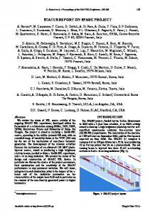
Figure 1: One of the original 1988 APE boards.
which are specifically optimized for their applications. In this paper we describe the Array Processor Experiment (APE) project, which was started in the mid eighties by the Istituto Nazionale di Fisica Nucleare (INFN) and is now carried out within the framework of a European collaboration with DESY and the University of Paris Sud. The structure of this paper is as follows: in the next section we briefly cover the older members of the APE family. We then describe in some detail APEmille, the APE generation currently used in physics production simulations. Subsequently, we discuss the architecture of apeNEXT, the new generation of APE systems. This is the most important part of our paper, followed by a short discussion of the apeNEXT software environment. The paper ends with some concluding remarks.
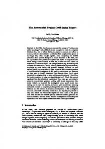
2. THE FAMILY OF APE MACHINE The evolution over more than one decade of APE systems is briefly recollected in Table I. The first generation of APE computers dates to the mid eighties. In Fig. 1, a picture of the original APE processor, made out of off-the-shelf electronic components is shown as a historical remark. APE100, the second generation of APE supercomputers, had been the leading workhorse of the European lattice community since the middle of the 1990s. Several parts of the APE100 machine are shown in Fig. 2. Commissioning of APEmille, the third generation of APE systems, started in the year 2000. These machines make a further 2 TFlops of computing power available to the LGT community. A description of the APEmille architecture is given in a later section. In order to keep up with future and growing requirements, the development of a new generation of THIT005
Figure 2: A APE100 board and a 6.4 GFlops APE100 crate operating at Parma University.
a multi-TFlops computer for LGT, apeNEXT, is in progress. The main goal [9] is the development and commissioning of a supercomputer with a peak performance of more than 5 TFlops and a sustained efficiency of O(50%) for key lattice gauge theory kernels. Aiming for both large scale simulations with dynamical fermions and quenched calculations on very large lattices the architecture should allow for large on-line data storage (of the order of 1 TByte) as well as input/output channels which sustain at least O(0.5) MByte per second per GFlops. Finally, the programming environment should allow smooth migration from older APE systems, i.e. support the TAO language, and introduce for the first time a C language compiler.
3. APEmille SYSTEMS APEmille is a massively parallel computer optimized for simulating QCD. The architecture is single instruction multiple data (SIMD) and all nodes run strictly synchronously at a moderate clock frequency of 66 MHz. The communication network has a three-dimensional topology and offers a bandwidth of
CHEP03, La Jolla, California, March 24th -28th , 2003
3
Table I Key parameter comparison of the APEfamily of supercomputer.
Architecture # nodes Topology Memory # registers (width) clock speed Total Computing Power of all
APE (1988)
APE100(1993)
APEmille (1999)
apeNEXT (2003-)
SIMD 16 flexible 1D 256 MB 64 (32 bit) 8 MHz 1.5 GFlops
SIMD 2048 rigid 3D 8 GB 128 (32 bit) 25 MHz 250 GFlops
SIMD 2048 flexible 3D 64 GB 512 (32 bit) 66 MHz 2 TFlops
SPMD 4096 flexible 3D 1 TB 512 (64 bit) 200 MHz 8-20 TFlops
Figure 3: The APEmille processing board, with its 8 nodes, is the smallest possible building block of an APEmille system.
66 MBytes/s/node. The smallest APEmille unit (see Fig. 3) is a processing board with 2 × 2 × 2 nodes. The largest stand-alone systems built until now consist of 4 × 8 × 8 nodes (see Fig. 4). Three different integrated circuits (ASICs) have been custom-developed for APEmille. Program execution is controlled by a control processor, which also performs the subset of integer arithmetics common to the whole SIMD partition. Computations using local integers and all floating-point operations are done in parallel by all computing nodes. At each clock cycle, the arithmetic processors are able to complete the “normal” operation a×b+c, where a, b and c are single precision (32 bit) complex operands. This gives a peak performance of 528 MFlops per node. Each node has 32 MBytes of local memory and a very large register file, holding up to 512 data words. Remote communications between the nodes are implemented as direct memory access which is controlled and routed by the communication processors. The processors are conTHIT005
Figure 4: Three APEmille racks at DESY Zeuthen. Each rack contains 2 × 2 × 2 computing nodes and has a peak performance of 130 GFlops.
trolled by very long instruction words (VLIW). This allows efficient scheduling of the microcode at compile time. Much effort has therefore been put into the development of software tools for generating efficient code (see later for more details). Loading of the executables and all other operating system services are handled via PCs running Linux. One host PC per four boards is directly attached to the APEmille backplane. It uses a PCI bus to communicate with the processing boards. The user interfaces with the system by logging onto an front-end PC, which is also running Linux and allows to spawn the program on
CHEP03, La Jolla, California, March 24th -28th , 2003
4
Table II The APEmille installations. Bielefeld 130 GFlops Zeuthen 520 GFlops Milan 130 GFlops Bari 65 GFlops Trento 65 GFlops Pisa 325 GFlops Rome 1 520 GFlops Rome 2 130 GFlops Orsay 16 GFlops Swansea 65 GFlops
Table III Key apeNEXT parameters. (2 crates) (8 crates) (2 crates) (1 Crates) (1 Crates) (5 Crates) (8 Crates) (2 Crates) (1/4 crates) (1 crates)
APEmille and to monitor its execution. Altogether, a large APEmille installation may be controlled by more than 20 PC’s. These are connected via an Ethernet network. APEmille machines are installed at several sites all over Europe, as detailed in table II. They provide a very stable and reliable computing environment, with typical up-times of the order of 85 %.
4. apeNEXT PROCESSOR AND GLOBAL DESIGN apeNEXT has been designed with the main goal of having an architecture as close as possible to its previous generation, as perceived at the user level, while improving on performance as much as possible through the use of more advanced technology. As a consequence, there are many similarities with previous generation systems, while a number of new design challenges had to be solved. For apeNEXT all processor functionalities, including the network devices, are integrated into one single custom chip running at a clock frequency of 200 MHz. Unlike former machines, the nodes will run asynchronously, which means that apeNEXT follows the single program multiple data (SPMD) programming model. Our performance goal is based on a peak performance of 1.6 GFlops per processor in 64-bit double precision, while the communication bandwidth between neighboring nodes is 200 MByte/s. We envisage large apeNEXT systems with 2000 processing nodes, delivering a peak performance of 3.2 TFlops. The key design parameters are listed in table III. Two new key features have been introduced in apeNEXT. First, apeNEXT is a SPMD (as opposed to SIMD) system. Each processing node is a fully independent processor, with a full-fledged flow-control unit and, of course, a number-crunching unit. The node has access to its own memory bank, where both program and data are stored. It executes its own copy of the program at its own pace. Nodes THIT005
clock frequency peak performance memory memory bandwidth network bandwidth register file instruction buffer
200 MHz 1.6 GFlops 256-1024 MByte/node 3.2 GByte/sec 0.2 GByte/sec/link 512 registers 4096 words
need to be synchronized only when a data-exchange operation is performed. This architecture may be labeled as a distributed-memory parallel computer, in which nodes exchange data through some sort of “message-passing” scheme. Internode communications are started by the program on the sending node that initiates a data communication step. This operation is matched by a corresponding instruction on the destination node, that explicitly receives the data packet. The latency associated to a “message” is extremely short, of the order of 2 to 3 times the latency associated to an access to local memory. For this reason, the actual data rate between nodes is bandwidthlimited (as opposed to latency-limited) even for short packets, so sequences of short accesses can be freely programmed without significant performance losses. This is an important feature in LGT, where the natural size of data packet transferred to remote processors is not larger than about 200 bytes. A second important architectural enhancement lays on the possibility of routing all read memory accesses (to local or remote nodes) through a receiving queue, which can be later accessed by the processor with zero latency. This feature is mainly used to perform data pre-fetch in critical kernel loops, taking into account that the address patterns are regular and easily predictable. The basic idea here is that all data items needed to perform iteration (i + k) (k = 1, 2, ...) of the loop are pre-fetched during iteration i and stored into the queue. When iteration (i + k) starts, data will be immediately available to the processor, effectively hiding almost all latency effects. Note that some of the memory accesses will be local, and some will be remote. They are started in sequence, but they may complete in a different order (a remote access may take longer than a local one). However, the queue mechanism automatically ensures that data are delivered to the processor in the same order in which they were requested from (remote or local) memory. The complete processing element is contained in just one custom-designed integrated circuit, called J&T, connected to a memory bank of 256–1024 MBytes with Double Data Rate (DDR) Dynamic RAM chips. In turn, the processor and its memory is housed on a small piggy-back printed circuit board shown in Fig. 6. This assembly is basically a com-
CHEP03, La Jolla, California, March 24th -28th , 2003
5
Program and Data Memory (DDR−SDRAM 256 M ... 1 G)
PMA
PC
MC
128
DMA
TX 128
128
LVDS
Instr. Buffer
local 64
7th link I2C interface interface
7th link interface
I2C
Queues
64 4
Register File 512 x 64 bit 5
Linux PC
128
Switch
Linux PC
Decompr.
1
3 2
128 128 128
AGU
128
64
Ethernet
LU INT LUT FPU Microcode
Figure 5: A possible apeNEXT configuration with 4 boards, 2 external LVDS-links for I/O, and a chained I2C-link for slow-control.
0
RX
host +x −x +y −y +z −z host +x −x +y −y +z −z
Disp.
Figure 7: Schematics of the apeNEXT J&T processor.
the “normal” floating-point operation a × b + c. At each clock cycle one normal operation can be started to provide a maximal throughput of eight floating-point operations per clock cycle. The operands are either complex values or pairs of real values. All floating-point data is represented in the 64-bit double-precision format of the IEEE standard. The integer unit (INT) operates on pairs of 64-bit integers. The arithmetic box also contains the logical unit (LU). Finally, a “special function” block (LUT) provides initial approximations for iterative or series-expansion evaluation of inverses, square-roots, logarithmic and exponential functions. Figure 6: The apeNEXT J&T module contains one custom designed VLSI J&T chip and nine 8x256 MBytes local DDR-SDRAM chips.
plete processor, that delivers more than 1.5 GFlops of processing power in double precision with a power consumption of approximately 7 Watt, that is about 10 times less than current generation high-end PCs. The compactness and the low power consumption of this basic building block are key ingredients to build the very compact multi-node system described later on. The block diagram of the J&T chip is shown in Fig. 7. It is a 64-bit architecture, optimized for floating point performance. We would like to highlight some selected details of the processor shown in Fig. 7: • A large register file of 256 registers each containing a pair of 64 bit words. All operands for the arithmetic unit arrive from the register file and all results are written back here. • An arithmetic box which performs floating point as well as integer operations. The basic operation executed by the floating point unit (FPU) is THIT005
• An address-generation unit (AGU) which computes addresses for memory access independently and concurrently with the main arithmetic box. This is an important feature to boost sustained performance. • A memory controller (MC) supporting a memory bank of 256–1024 MBytes based on standard DDR-SDRAM. The memory is used to store both data and program instructions. A consequence of this organization is that conflicts between data and instruction load-operations are present. Two strategies have been employed to avoid these conflicts. First, the hardware supports compression of the microcode. The compression rate depends on the level of optimization, typically values are in the range of 40–70%. Instruction de-compression is performed on-thefly by dedicated hardware. Second, an instruction buffer allows pre-fetching of (compressed) instructions. Under complete software control, a section of the instruction buffer can be used to store performance critical kernels for repeated execution. • A flow-control unit that executes programs specified as a sequence of compiler prepared mi-
CHEP03, La Jolla, California, March 24th -28th , 2003
6
crocode words, using the VLIW control style. • A network interface which contains seven LVDS link interfaces. Each link is bi-directional allowing send and receive operations to run concurrently. Once a communication request is queued it is executed independently of the rest of the processor, which is a prerequisite for overlapping network and floating point operations. Each transmitter (TX) is able to send one byte per clock cycle, i.e. the gross bandwidth is 200 MByte per second per link. Due to protocol overhead the effective network bandwidth is ≤ 180 MByte per second. The network latency is O(0.1 µs) and therefore at least one order of magnitude smaller than for today’s commercial high performance network technologies. While six links are used to connect the processing node to its neighbors, the seventh link is used for input/output operations.
X+(cables) 12 13
14
15 8
9
10 11
4 5
6 7
0 1
Z+(bp)
2
Y+(bp)
3 DDR−MEM X+
J&T Z−
• A set of fifos that implements the queue mechanism described earlier in the text: – A first set of fifos (the TX ones) hold the data words received from the main memory (or the register file) until the network is able to send them to another node. The main role of this system is to decouple the (fast) memory system from the (slower) network links. – A second set of fifos receives data items from the network and stores them until the processor wants to load them into the register file. – Finally, a third set of fifos is used to keep control information. These fifos are needed to guarantee the correct order of the data bursts. • A slow serial interface based on the I2C standard, used for system initialization, debugging and exception handling. The overall structure of an apeNEXT system is similar to APEmille. We have a three-dimensional array of processors (see Fig. 5). Periodic boundary conditions are applied. Although all nodes are connected to their nearest neighbors only, the hardware allows routing across up to three orthogonal links to all nodes on a cube, i.e. connecting nodes at distance (∆x , ∆y , ∆z ) with |∆i | ≤ 1. Clusters of 16 apeNEXT processors will be assembled onto just one printed-circuit board. The processors are arranged in the configuration of a threedimensional structure of 4 × 2 × 2 processors (see fig. 8). A set of 16 boards is housed within one system crate. All communication links between these nodes are established through the crate backplane. THIT005
Figure 8: The connection layout of the sixteen J&T nodes in each apeNEXT processing board. Note that the connection between nodes in different processing boards is realized through the back plane for communication along the Y and Z directions and using front-plugged cables for communication in the X directions.
Larger systems are assembled connecting together several crates using external cables. The system is completed by a number of host PCs that can be tailored to match user-specific input/output requirements (see fig. 5). The main input/output channel is based on one of the seven data links available on each processor. One such link from each processing board can be connected to a host interface board that follows the PCI specifications and can be plugged into a standard PC (see Fig. 9). The actual number of input/output channels can be tailored to match user-specific input/output requirements. From the apeNEXT point of view, an input/output operation is simply a remote communication with a special remote node. This structure has the main advantage of requiring a minimum of programming and operating system overhead.
5. SOFTWARE AND BENCHMARKS We will provide both a TAO and a C compiler for apeNEXT. The latter is based on the freely available lcc compiler [10] and supports most of the ANSI 89 standard with a few language extensions required for a parallel machine. Both compilers generate a high-
CHEP03, La Jolla, California, March 24th -28th , 2003
*.zzt
rtc
7
*.c Zz parser kernel (vraps) asm generator
*.sasm
mpp
nlcc
frontend (trees, symb.) backend
*.sasm macro expansion label analysis cache utilities
*.masm muladd fusion removal sofan move dead code removal AGU−optimisation
*.no
sf
functional simulation
*.masm scheduling allocation shaker register label resolution compression *.nex
linker *.nex
Figure 10: An overview on the compilation procedure.
Figure 9: The apeNEXT custom made PCI interface. It provide the interface between the host Linux PC and the apeNEXT system. On board there are two 0.2 GByte/sec fast 7th -link communication channels and a slow I2C controller.
level assembly. A assembler pre-processor (mpp) is used to translated this into a low-level assembly. For machine specific optimizations at this assembly level, e.g. address arithmetics and register move operations, the software package sofan is under development. Finally, the microcode generator (shaker ) optimizes instruction scheduling, which for APE machines is completely done in software. We finally plan to develop a linker which allows to combine several microcode files into one executable. An overview on the compilation chain is shown in Fig. 10. For most parts of the compiler software stable prototype versions are available and were already used to benchmark the apeNEXT design. For this purpose we considered various typical linear algebra operations, like the product of two complex vectors. To execute this operation iteratively needs reading two complex numbers per iteration, which on apeNEXT takes at least two clock cycles. The arithmetic instructions executed per iteration, however, have a throughput per clock cycle of up to one. Therefore, this operation is on apeNEXT restricted by the memory bandwidth THIT005
and the theoretical sustained performance therefore limited to 50%. From VHDL simulations that include all machine details the efficiency was found to be 41%. Even higher performance rates can be achieved for operations where the data after being loaded to the register file is re-used several times. This is, e.g., the case when multiplying arrays of SU(3) matrices. For this operation we measured an efficiency of 65%. In QCD simulations most of the time is spent applying the Dirac operator, e.g. the Wilson-Dirac operator M = 1 − κH. Therefore, we investigated the multiplication with the so-called hopping term, i.e. Hψ. This operation involves remote communications and therefore depends on the number of processors involved. The maximum number of processors is limited by the size of the problem, i.e. the lattice volume. In case of dynamical fermion simulations a multiplication with the hopping term has to be done much more often than updating the gauge fields. We therefore kept a local copy of the gauge fields to save network bandwidth. Considering the worst case where the problem is distributed over the maximum number of processors, we found the sustained performance to be 56%. This figure is made possible by extensive use of the pre-fetch features of the processor, which allowed to completely overlap floating point operations and network communications, such that the time when the processor waits for data becomes almost zero. This eventually indicates an excellent scaling behavior of the apeNEXT architecture.
CHEP03, La Jolla, California, March 24th -28th , 2003
8
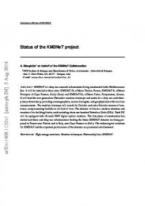
6. OUTLOOK AND CONCLUSIONS The hardware design of the next generation of APE custom built computers has been completed. Prototype boards and the communication backplane are already available. A prototype apeNEXT processor is expected out of the foundry in late August 2003. A larger prototype installation is planned to be running by end of 2003. There exists a stable prototype version for all parts of the compiler software. Based on this software we expect that key lattice gauge theory operations will be able to run at a sustained performance of O(50%) or more. We hope that apeNEXT will be a key element of LGT simulations in the next few years.
Acknowledgments We would like to thank W. Errico for his important work in the early phases of the project, and A. Agarwal, T. Giorgino and M. Lukyanov for their contributions.
References [1] N.H. Christ, Computers for lattice QCD, Nucl. Phys. (Proc. Suppl.) 83–84 (2000) 111.
THIT005
[2] R. Gupta, General physics motivations for numerical simula-tions of quantum field theory, Parallel Comput. 25 (1999) 1199. [3] I. Montvay, G. M¨ unster, Quantum Fields on a Lattice, Cambridge University Press, 1994. [4] K.G. Wilson, Confinement of quarks, Phys. Rev. D 10 (1974) 2445. [5] A. Bode et al. [ALPHA Collaboration], Phys. Lett. B 515, 49 (2001) [arXiv:hep-lat/0105003]. [6] P. Boucaud et al. [The SPQ(CD)R Collaboration], Nucl. Phys. Proc. Suppl. 106, 329 (2002) [7] F. Jegerlehner et al., Requirements for high performance com-puting for lattice QCD: Report of the ECFA working penal, Preprint ECFA/99/200. [8] M. L¨ uscher, Nucl. Phys. Proc. Suppl. 106, 21 (2002) [arXiv:hep-lat/0110007]. [9] R. Alfieri et al. (apeNEXT-collaboration), “apeNEXT: A Multi-Tflops LQCD Computing Project”, 2001 [arXiv:hep-lat/0102011]. [10] C.W. Fraser, D.R. Hanson, D. Hansen, “A Retargetable C Compiler: Design and Implementation”, 1995.