Fibonacci and Lucas numbers come out from the analysis of the power distribution .... ence is in the fact that the last cell of the Figure 5 network has a "load" ...
THE APPEARANCE OF FIBONACCI AND LUCAS NUMBERS IN THE SIMULATION OF ELECTRICAL POWER LINES SUPPLIED BY TWO SIDES Giuseppe Ferri Dipartimento di Ihgegneria Elettrica-FacoM di Ingegneria, Universita di L'Aquila Localita Monteluco di Roio, 67040 Poggio di Roio, L'Aquila, Italia (Submitted October 1995)
INTRODUCTION In the analysis of some physical structures, the possibility of modeling them with an electrical circuit is particularly important because it allows the determination of the characteristic behavior by means of a simple circuital analysis. Moreover, it is also interesting to have a different method of measurement evaluation, comparable with the "direct" one, which sometimes either is not simple or requires the use of computer programs which on some occasions do not go into convergence. Finally, it can make a contribution to the mathematical interest in testing of network software algorithms for solving linear equation systems. In this article, a symmetrical ladder network is used as a model for the simulation of electrical power lines. Fibonacci and Lucas numbers come out from the analysis of the power distribution among the users. The electrical characteristics of the ladder network have also been determined in a closed form using a theory previously developed by the author [1]. 1. MODELING OF A POWER ELECTRIC LINE Let us consider a high voltage electric line, supplied by the two sides, which gives power to users distributed along the line, as in Figure 1.
V.
0
0 user 1
Vr
user n
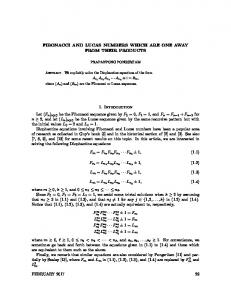
FIGURE 1. The Electrical Power Line Supplied by Two Sides A ladder structure (Fig. 2) can be used as a discrete electrical model of the power line. For the sake of simplicity, we consider n users who have equal consumption, represented by n equal vertical impedances Z2, placed at equidistant points characterized by equal horizontal impedances 1997]
149
THE APPEARANCE OF FIBONACCI AND LUCAS NUMBERS IN THE SIMULATION OF ELECTRICAL POWER LINES
Z1 0
V.
I1
t\
21
Z1 X
1 k
i
1 Z2
.
.
Z1 n
n -1
n+
f
c Z2
h2[
Z2
h
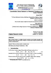
FIGURE 2, Ladder Network as a Model of the Power Line 2. ANALYSIS OF THE LADDER NETWORK In order to analyze the network of Figure 2, we can use the superimpositlon of the effects in the networks of Figures 3 and 4. The analysis of these networks can be done starting from the study of the network of Figure 5, by adding a "load11 impedance. Z1
Z1
u
V
X
1
A^ )
—
* •
Z1
n-1
n = oul
Z2
72
72
n
FIGURE 3, Ladder Network Supplied by VA Z1
Z1
72
n l
Z1
1 n+1
O
12
FIGURE 4. Ladder Network Supplied by VB 0
VC)
I
Z1
Z1
1 1
72
n-1
Z2
I
Z1
I
n
72
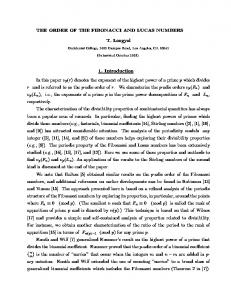
FIGURE 5. Ladder Network with n Identical Cells 150
[MAY
THE APPEARANCE OF FIBONACCI AND LUCAS NUMBERS IN THE SIMULATION OF ELECTRICAL POWER LINES
In [1] a new fast method for the ladder network characterization in Figure 5 was presented; by using this method, all the electrical parameters of a ladder network formed by n identical cells can be written directly by means of both a parameter that characterizes the single cell [the "cell factor11 K(s) = Zx(s) / Z2(s)} and the polynomials in K whose coefficients are the entries of two numerical triangles, named DFF [3] and DFFz [4], here reported: n
K°
0
1
1
1
1
2
1
3
1
3
1
6
5
K1
K2
K3
1
n
K°
0
1
1
2
1
2
3
4
1
3
4
10
6
Kl
K2
K3
1
DFF Triangle
DFFz Triangle
Entry = n + K n-K
Entry = n + K + l n-K
The mathematical properties of triangles and polynomials have been presented in [2]. Let us call b„ and B„ the polynomials whose coefficients are the entries of DFF and DFFz triangles, respectively. These polynomials coincide with the polynomials defined by Morgan-Voyce and then investigated by Swamy [7] and Lahr [5] and [6]. All the electrical characteristics of the network represented in Figure 5 can be expressed directly in a closed form by means of these polynomials if all the cells are equal. The networks drawn in Figures 3 and 4 are very similar to that of Figure 5. The only difference is in the fact that the last cell of the Figure 5 network has a "load" impedance of infinite value. It is possible to write the electrical expressions for the Figure 3 and Figure 4 networks as simply as for the Figure 5 ones and also in closed form. For the Figure 3 network, we have (see [5], p. 275) that the transfer function is given by V
VA
1
(1)
Bn(K)>
while the voltage at the generical Xth node is given by (2) •D«(A)
with B_r(K) = 0. The voltage behavior for the network of Figure 4 is symmetrical. For that reason, we can write W ^ B T l i
(3)
( 0 < X < ^ + 1).
By the application of the superimposition of the effects, we can write, for the network represented in Figure 2, the following expression for the node voltages: VX(K) = V>(K) + V>'(K) = VA Bn(K) 1997]
B
Bn{K)
(0