Cisco. AGS+ Router. 300 area APS networks. Cisco 7000 Router with 5 FDDI ... network and software-controlled interfaces to hardware. .... monitor board(Fiber).
The APS Control System Network Kenneth V. Sidorowicz and William P. McDowell Argonne National Laboratory Abstract The APS accelerator control system is a distributed system consisting of operator interfaces, a network and computer-controlled interfaces to hardware. This implementation of a control system has come to be called the “Standard Model.” The operator interface is a UNIX-based workstation with an X-windows graphical user interface. The workstation may be located at any point on the facility network and maintain full functionality. The function of the network is to provide a generalized communication path between the host computers, operator workstations, input/output crates and other hardware that comprise the control system. The crate or input/output controller (IOC) provides direct control and input/output interfaces for each accelerator subsystem. The network is an integral part of all modern control systems and network performance will determine many characteristics of a control system. This paper describes the overall APS network and examines the APS control system network in detail. Metrics are provided on the performance of the system under various conditions.
The World Argonne FDDI
Cisco AGS+ Router
APS Firewall Router 300 area APS networks
User Residence Facility FDDI
Cisco AGS+ Router
APS FDDI
CLO 3,4,5 & URF 2
MMAC+ Hub
Controls Cisco 7010 Router
CLO 1,2, & 400 2
2
2
2
2
MMAC+ Hub LOM Controls
out of band network managment
To IOCs & Servers
File Servers & Storage
Cisco 7000 Router with 5 FDDI
2
To file servers
Hub 1
Hub 1 2
2
Hub 1
2
LOM FDDI 2
2
Cisco 70X0 Router 431 - Loco
Hub 2
2
Redundant FDDI
2
2
2
2
431 LOM Routers 432 433 434 435 438
Local LOM FDDI
Local LOM FDDI
Hub 10
LOM LOM 8LOM 8LOM 8 8 HubHub 1 Hub 1 Hub 1 1
LOM 1 Hub 1 Controls FDDI includes Front Ends and Insertion Devices
Cisco 70X0 Router
To file servers
2
Hub 2
Hub 2
2
Hub 11
User Residence Facility Hubs
Central Lab-Office Hubs
HUB FDDI
LOM 1 Hub 2
To Desktop and Beamlines
LOM 1 Hub n
To Desktop and Beamlines
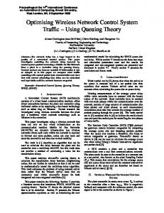
Figure 1 The APS Network
INTRODUCTION Figure 1 gives an overview of the complete APS computer network including that portion of the network which is used to control the accelerators. All of the APS networks, including the accelerator control network, use optical fiber to connect satellite network hubs to a collapsed-backbone FDDI concentrator system. All the hubs are dual attached to the concentrator using a star connection configuration. The APS FDDI connects to the Argonne central FDDI network and then to the internet through a firewall router. The APS FDDI ring is presently configured to serve two locations 1.5km apart. In a few months the APS staff members will
be located at one point and this FDDI ring will function only to implement the firewall and provide a defined point where network responsibilities shift from the APS network staff to the Laboratory network staff. The APS network must serve several diverse functions including accelerator control, beamline control, experimental data acquisition and normal day-to-day computerized office functions such as word processing. A router is used to isolate the APS network functions. The network lis divided into the control system, the beamlines in the Laboratory Office Modules (LOMs), the Central Laboratory Office Building (CLO), and the User Residence Facility (URF). Each LOM is provided with a secure network closet in which all data network wiring is terminated and which houses the interface equipment needed to connect the collaborative access team (CAT) offices, beamlines, and CAT-provided local computers to the APS-provided network equipment. As shown on Figure 1, each LOM includes a router and a hub system which provides slots for Ethernet and Category 5 interfaces to the labs, offices, and beamlines. As they are needed, additional and higher-performance cards can be added to provide FDDI/CDDI (100 Mb/s) or ATM (up to 600 Mb/s) service to the CATs. Routes directly over planned national ATM networks will allow CATs to route data or “virtual presence” control between their home institution and the APS. The network hub equipment and cabling plant allows an upgrade path to ATM technology (600 Mb/s) when this is needed. In addition, all connections and equipment will allow fail-over to redundant paths and equipment. The same equipment and strategy has been followed in the CLO and the URF buildings. Thus, as with the LOMs, the computers installed in offices, labs, and residence rooms will use Category 5 wiring at 10 Mb/s Ethernet rates and be able to upgrade to 100 Mb/s CDDI rates on an incremental basis.
THE ACCELERATOR CONTROL STSTEM The APS accelerator control system has been implemented using the Experimental Physics and Industrial Control System (EPICS) software tool kit. EPICS supports the “standard model” distributed control system which consists of operator interfaces, a network and software-controlled interfaces to hardware. At the APS, the operator interface is a UNIX workstation with an X-windows graphical user interface which may be located at any point on the accelerator control network and maintain full functionality. An operator has the ability to generate and alter control displays and to access applications such as the alarm handler, the archiver, interactive control programs, custom code and other tools. There are 16 operator interfaces directly connected to the APS control system.The crate or input/output controller (IOC) provides direct control and input/output interfaces for each accelerator subsystem. The standard crate uses either the VME or VXI standard, a Motorola 68040 processor, network communications and a variety of signal and sub-network interfaces. The 68040 processor provides the crate with the intelligence to allow it to run its software autonomously with respect to all other devices in the system. The software running in the crate hides hardware dependencies from the high-level software running on the workstation. There are approximately 130 crates used in the accelerator control system. A real-time operating system, VxWorks, is run in the crate CPU to provide the basis for the real-time control. EPICS uses the TCP/IP networking protocol, a commercial standard supported by all network hardware vendors. The TCP/IP implementation is independent of the particular network medium selected to implement the network. The function of the APS controls network is to provide a generalized communication path between the host computers, operator workstations, input/output crates, and other hardware that comprise the control system. The network design has taken into account the networking requirements of the EPICS networking interface, Channel Access (CA). Channel Access is a ‘software bus’ which allows various EPICS entities to communicate over the network. Channel connections are made when a CA client starts up and sends a network broadcast containing the unique name or list of unique names of the process variables that it wishes to find. Each channel access server on the subnet searches it's list of process variables and establishes a TCP connection with the client if any desired process variables are found. This behavior dictates the overall design of the control system network. It must be internally bridged in order to support the CA broadcasts and it must be separated from the other APS networks by a router to provide security for the accelerator controls.
Router Router
out of band network managment to IOC and Hub Serial Ports
To IOCs & Servers
Hub Collapsed Backbone FDDI
Hub 1
Hub 2
Dual Attached FDDI
Hub 9
Hub 10
Figure 2 APS Control System Network A block diagram of the APS control system hub network is shown in Figure 2. The APS router, a Cisco 7513, is used to provide subnet separation for the control system and to provide the controls network with a subnet address. The router has a 100MHz MIPS 4600 processor and a 2-Gb/s backplane. An FDDI output card in the router is attached to one of the collapsed backbone FDDI buses on the Cabletron MMAC Plus enterprise hub. This hub was selected to provide high availability network services to the APS
control system. The MMAC Plus hub accommodates 14 interface modules and has fault tolerant features built into it. It has two dual FDDI networks which provide up to 400 Mb/s of network bandwidth and it will support both packet and ATM cell transport. There are ten satellite Cabletron MMAC hubs in the controls network which are dual attached to the central MMAC Plus hub using FDDI. The MMAC hubs are distributed throughout the accelerator facility to provide local Ethernet connections to all network devices. The aggregate throughput of the device is 26,180 packets per second. There are four hubs serving the storage ring, two serving the rf system, two serving the injector system and two serving the systems in the main control room. All the hubs are connected to the MMAC Plus hub using a star configuration. This allows us to reconfigure the network if future technology, such as ATM, should be installed. All of the control system IOCs are connected to the hubs using fiber Ethernet and thus they can be reconfigured if required. To provide redundant service, every IOC is connected to two hubs using a redundant fiber Ethernet transceiver: a primary hub with fibers running clockwise from the IOC to the hub and a secondary hub with fibers running counterclockwise from the IOC to the hub. This allows a hub to be serviced or to fail without causing the IOC to lose communication with the network.
/1 To Event Generator
To System Monitor Board (Fiber)
\1
IOC xcvr
/1 To Event Generator
IOC
\1 SMB \2
\2 \2
xcvr
/1 To Event Generator
\1 SMB \2
\2 \2
\2 \2
IOC
\1
IOC xcvr
/1 To Event Generator
SMB \2
xcvr
\2
\1 SMB \2
\2
/1 To Event Generator
IOC xcvr
\1 From adjacent system monitor board(Fiber) \2 \10
Serial fiber to Terminal server
\10
Redundent fibers to adjacent hub Network Connection.
\2 \2
HUB Redundent fibers to adjacent hub Network Connection.
\10
\4
To front end IOCs (10) ID IOCs (5) BPM & Diagnostic IOCs (5) Global Orbit Correction IOCs (5) FDDI Star to MCR
Storage Ring Network
Figure 3 IOC Fiber Plant Figure 3 shows a typical connection of the vacuum/power supply IOCs in five sectors of the storage ring. The IOCs are grouped in 20 locations around the storage ring. There are additional IOCs not shown in this area which are used to control the diagnostic devices, the front-end equipment and the insertion devices and to run the global orbit correction system. These IOCs are connected in the same way to the vacuum/power supply IOCs but are omitted here to simplify the diagram.
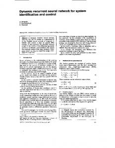
NETWORK TESTING Normal network traffic on the control system FDDI is shown in Figure 4. With all accelerator systems running, the average network utilization is close to 4%. On October 13th the storage ring was not operating. Beginning at approximately 0800 on October 14th, the accelerator systems was brought on-line. At 1803 the linac e-gun was turned on. During this time network utilization increased from approximately 2% of capacity to 4% of capacity and remained at 4% until the shutdown at midnight October 15th. The accelerator was not running from October 16th through October 18th. Since this was a scheduled shutdown, the subsystem groups, including controls, were testing systems during the day shift. Network maintenance and reconfiguration was performed during this time. In order to stress test the network, an EPICS server IOC and an EPICS display manager client (MEDM) were connected. The number of events per second was recorded; these are a measure of network and IOC capacity. We have noticed differences in the maximum rate attainable when the IOC and workstation are on the same Ethernet segment compared with when the IOC and workstation are connected to different Ethernet segments which are connected by the controls FDDI and the hubs. There seems to be a degradation in performance when connecting through the hub. The cause of this performance degradation will be investigated further and reported at the next opportunity.
October 14, 1995 Saturday
October 13, 1995 Friday Utilization
Utilization
26.00
26.00
24.00
24.00
No Accelerator Operations Baseline network utilization of 2%
22.00
20.00
18.00
Accelerator Operations Start at 0830
22.00
20.00
18.00
16.00
16.00
14.00
14.00
12.00
12.00
10.00
10.00
8.00
8.00
6.00
6.00
4.00
4.00
2.00
2.00
IOC Reboot
0.00
0.00
Time
Time 12.00
14.00
16.00
18.00
20.00
22.00
0.00
24.00
5.00
10.00
15.00
20.00
24.00
October 16, 1995 Monday
October 15, 1995 Utilization
Utilization
26.00
26.00
24.00
24.00
22.00
22.00
20.00
20.00
18.00
18.00
16.00
16.00
14.00
Workstation Rebooted
14.00
Beam Dumped
12.00
10.00
beam to ring
8.00
12.00
40 ma stored
10.00
Shift Ends
8.00
6.00
6.00
4.00
4.00
2.00
2.00
0.00
0.00 Time 0.00
5.00
10.00
15.00
20.00
Time 0.00
24.00
5.00
October 17, 1995 Tuesday
10.00
15.00
20.00
24.00
October 18, 1995 Wedmesday
Utilization
Utilization
26.00
26.00
24.00
24.00
22.00
22.00
20.00
20.00
18.00
18.00
16.00
network maintainance starts
server maintainance
16.00
14.00
14.00
network maintainance starts
12.00
10.00
8.00
12.00
10.00
Ends
Ends
8.00
6.00
6.00
4.00
4.00
2.00
2.00
0.00
0.00 Time 0.00
5.00
10.00
15.00
20.00
24.00
Time 0.00
5.00
10.00
15.00
20.00
24.00
Figure 4. FDDI Performance
CONCLUSION The APS controls network has met all requirements for a high availability, minimum latency system and has been a significant help in supporting the commissioning activities. There are a few areas where improvements in performance are still being investigated and these will be reported at a later date.
ACKNOWLEDGEMENT This work was supported by the U. S. Department of Energy, Office of Basic Energy Sciences, under contract No. W-31-109ENG-38.