1
The ARISE Approach for Extending Embedded parts that loosely interact with the remaining parts of the application, which are executed by the processor. In most of Processors with Arbitrary Hardware the cases, due to the loose interaction between them, both the Accelerators* Nikolaos Vassiliadis, George Theodoridis, and Spiridon Nikolaidis email:
[email protected] Abstract—ARISE introduces a systematic approach for extending once an embedded processor to support thereafter the coupling of an arbitrary number of Custom Computing Units (CCUs). A CCU can be a hardwired or a reconfigurable unit, which can be utilized following a tight and/or loose model of computation. By selecting the appropriate model of computation for each part of the application, the complete application space is considered for acceleration, resulting in significant performance improvements. Also, ARISE offers modularity and scalability and is not restricted by the opcode space and operands limitation problems that exist in such type of machines. To support these features we introduce a machine organization that allows the co-operation of a processor and a set of CCUs. To control the CCUs we extend once the instruction set of the processor with eight instructions. To efficiently incorporate these features to an embedded processor, we propose a micro-architecture implementation that minimizes the control and communication overhead between the processor and the CCUs. To evaluate our proposal we extended a MIPS processor with the ARISE infrastructure and implemented it on a XILINX FPGA. Implementation results, demonstrate that the timing model of the processor is not affected. Also, we implemented a set of benchmarks on the ARISE evaluation machine. Performance results prove significant improvements and reduced communication overhead compared to a typical co-processor approach.
I. I NTRODUCTION Integrating Custom Computing Units (CCUs), implemented in ASIC or reconfigurable technology, to a processor is an effective way to meet the computational demands of modern applications. In such systems, the base Instruction Set Architecture (ISA) of the processor serves as the bulk of flexibility to execute any algorithm, while the CCUs are exploited through Instruction Set Extensions (ISEs) to accelerate the execution of computational-intensive parts of the application. Furthermore, providing CCUs with the capability to reconfigure their functionality, high flexibility is achieved. Reconfigurable units provide dynamic ISEs offering the adaptation of the system to the target application. Although the extension of a processor with reconfigurable CCUs increases the performance and flexibility of the system, performing the extension in an ad-hoc manner results in several limitations which affect strongly in many cases- performance, cost, and development time. These limitations are discussed in the following: Computational model limitation. Based on the approach followed to couple the CCUs to the processor, the existing systems can be divided in two categories. In the first one [1], the CCUs are loosely-coupled to the processor following a co-processor model of computation. In these systems, the CCUs undertake the execution of computational-intensive *This is a draft version of the paper accepted for publication in IEEE Transactions on Very Large Scale Integration (VLSI) Systems
processor and the CCUs operate concurrently resulting in high performance. However, the control of the CCUs and the data communication between the CCUs and the processor are done explicitly through a number of instructions. This results in a communication and control overhead, which may eliminate the performance gains if autonomous tasks can not be found. In the second category [2], the CCUs are tightly-coupled to the processor and treated as functional units of the processor’s datapath. In these systems the CCUs execute finegrain tasks that strongly interact with the execution flow. The communication between the processor and CCUs is performed through the register file, while the operations that are executed by the CCUs are identified and controlled via opcodes that are encoded in the instruction word. Thus, the communication and control overheads are reduced. However, due to the fine-grain granularity of the tasks and since concurrent operation of the processor and CCUs is not supported, limited performance improvements are obtained. It is clear that each of the above computational models exhibits advantages and disadvantages making it preferable for specific type of applications. Thus, supporting only one model may lead to unexploited performance gains. Limited modularity. Following an ad-hoc approach, the implementation of an operation on CCUs satisfies only the specifications of the considered system (e.g. the used technology and CCUs). This reduces the modularity as it becomes difficult to port a CCU implementation of an operation, which has been developed without taking account the specifications of the new system. Also, the extension of the system with new CCUs becomes difficult reducing its scalability. Operands limitation. In most of the existing systems the number of input/output operands of the operations that are mapped to the CCUs is limited. For example in [3], [4] each CCU executes 2 input/1 output operations. This prevents clusters of operations with more inputs/outputs to be executed by the CCUs resulting in unexploited performance improvements [5], [6]. Also, in other cases as in [7] the ports of the register file are extended to provide the necessary operands, which may be not easily applicable. Opcode space explosion. Usually, each operation executed by a CCU is encoded with a different opcode (i.e. with a new instruction) [2], [8], [9]. However, since the available opcode space of the processor is limited, the number of operations that can be executed by CCUs is also limited. Thus, performance improvements may be reduced when a large set of different operations must be executed by the CCUs [10]. To address the above limitations, we introduce the Aristotle Reconfigurable Instruction Set Extensions (ARISE) framework. ARISE proposes a systematic approach to extend once a processor to support thereafter any number and type of CCUs. To achieve this: i) a machine organization, which allows the co-operation of the CCUs and processor, is proposed, ii) the ISA of the processor is extended once with eight new instructions called ARISE ISE to control the CCUs, and iii) a micro-architecture is introduced, and a programming model is
2
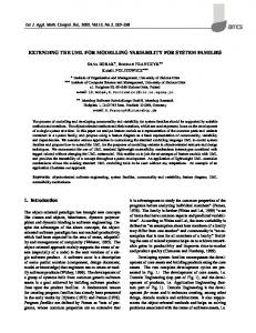
proposed. After the development of an ARISE-aware machine, an arbitrary number and types of CCUs can be easily coupled to the processor. The CCUs can be exploited following a tight, loose, or hybrid model of computation, based on the characteristics of the application(s). This paper presents the ARISE framework, discusses the performed extensions on the processor and study how the above-mentioned limitations are addressed. To evaluate our proposal a MIPS-I processor core was extended and implemented on a Xilinx FPGA. Synthesis results validates that the performed extensions do not affect the timing model of the processor. A set of benchmarks was implemented and the experimental results prove the efficiency of the proposal. Specifically, exploiting the hybrid model of computation, the ARISE machine achieves performance improvements of up to 68% compared to a typical approach where only one of the computational models is supported, while it also addresses the previous-mentioned drawbacks. The rest of the paper is organized as follows. Section II presents the general organization of ARISE machines and the ARISE ISEs. Section III focuses on the micro-architecture, while Section IV discusses, through an example, the general approach followed to program ARISE machines. Experimental results are presented in Section V. Section VI discusses the related work, while conclusions are given in Section VII. II. M ACHINE O RGANIZATION AND ISE Our approach assumes that computation-intensive parts of the application have been identified and each of them can be more efficiently executed on a CCU of an ARISE machine as a single operation, called ARISE operation. Such an operation may be as simple as a few nodes of the application’s DFG or as complex as a kernel. An ARISE machine, which is depicted in Figure 1, consists of: a) the Core Processor (CP), b) the ARISE instruction decoder, c) the ARISE interface, and d) the CCU wrappers. The interface is further divided into: i) the control unit, ii) the Opcode-to-Id table, and iii) the Input/Output Buffer (IOB). The extension of the processor with the interface is performed once. Then, an arbitrary number of CCUs can be attached, via the interface, employing a wrapper for each CCU. Also, a CCU can be a hardwired or reconfigurable unit. To provide CCUs with configuration bits and data, the memory is accessed through the memory ports of the processor. Extra memory ports, dedicated to provide data and/or configuration to the CCUs, can be supported to increase performance. Also, a dedicated memory for storing the configuration bits of the CCUs can be used. To utilize the CCUs, the processor’s ISA is extended once with a set of specific instructions, called ARISE instructions, which control: 1) the execution of the ARISE operations on the CCUs, 2) the data communication between the CP and the CCUs, and 3) the configuration of the CCUs. All ARISE instructions have the same format that includes three fields. These fields define: i) the ARISE instruction (instr), ii) the opcode (opc) of an ARISE operation, and iii) the operands (operands) of the instruction. To extend the CP’s ISA with ARISE instructions these fields are encoded in the
ARISE Instruction Decoder
Control Unit
Memory Hierarchy
Instructions
Core Processor
DataPath
Data
ARISE Interface ARISE Dedicated Configuration Memory
Fig. 1.
Control Unit
ARISE Configuration
Input/Output Buffer
CCU Wrapper
CCU Wrapper
CCU1
CCUn
ARISE Dedicated Memory Ports
Organization of an ARISE machine opcode
One reserved ARISE opcode
Fig. 2.
Opcode-toId Table
operands
sec
instr opc
Processor Instruction Word
operands
ARISE Instruction Word
Encoding of the ARISE instruction word
instruction word of a CP as shown in Figure 2. As an example, a processor’s instruction word format is assumed of which only one opcode, of the available ones of the CP, is reserved for all ARISE instructions. The secondary field, sec, is used to encode both the instr and opc fields, while the operands fields are the same. The operands of an ARISE instruction are accessed via the register file of the CP. It should be noted that the instruction word format in Figure 2 is typical for embedded processors, like ARM, MIPS, and PowerPC. Therefore, the extension is similarly possible for a wide range of embedded processors. Instructions are pre-decoded by the ARISE Instruction Decoder to determine their type (CP or ARISE instructions) and they are issued to the CP or to the interface. Utilizing the Opcode-to-Id Table, the opc field, which has limited bit-width, is assigned to a unique identifier, Id, which can be of arbitrary size. The Id specifies an ARISE operation implemented on a CCU. The table also allows the dynamic (at execution time) re-assignment of the opc to an Id. Thus, the same opc in an ARISE instruction can be assigned to different ARISE operations alleviating in that way the opcode space explosion problem. Also, the assignment of opc to ARISE operations is not fixed. Thus, new CCUs and ARISE operations can be easily included assigning each operation to an Id. In that way, the modularity and scalability of the machine is enhanced. Since an ARISE operation can be referenced through the opc, which is encoded in the instruction word of the processor, the control communication overhead is minimized. The IOB provides temporary storage space for the operands of an ARISE operation. It is exploited (through a sequence of move instructions) to support operations with more operands than the CP’s register file provides/accepts per instruction. It
3
is also configured to utilize the complete bandwidth of the register file (i.e. all register file ports). Thus, the operand limitation problem is addressed with minimum data communication overhead (without considering the case of increasing the register file ports). The wrapper controls the configuration and execution of an ARISE operation. It also serves the memory accesses of the CCUs through the CP’s memory ports. Moreover, it is used for storing the ARISE configuration bitstream for each operation. Two types of configuration bitstreams exist in an ARISE machine. The first is the typical one required by the reconfigurable CCUs and it is provided by the CCU’s vendor tools. The second one, is the ARISE configuration bitstream that specifies the way an ARISE operation is handled by the interface. Specifically, for each operation the ARISE configuration bitstream defines: 1) if it accesses the data memory, 2) if its latency is known or not at compile time, 3) its latency (CP cycles), and 4) its exception policy. Thus, the ARISE operation is handled by the micro-architecture without being exposed to the architecture. The ARISE instructions can be tuned-up at design time to match the characteristics of the CP. The typical configuration presented below assumes that the register file provides at least two read and one write port, which is a typical case for embedded processors. It can be also configured to utilize register files with more ports. The typical configuration contains the following ARISE instructions: confopc2id {opc}, {id}: The “configure opcode-to-id” instruction assigns the opcode of an ARISE operation to a unique identifier Id. This assignment is stored in the Opcode-to-Id table. confld {opc}, {start addr}, {end addr}: The “load configuration” instruction is responsible for loading of ARISE and CCUs (if reconfigurable CCUs are used) configuration bitstreams. The start addr and end addr operands determine the memory space where the bitstreams are placed, while the opc corresponds to the opcode of the ARISE operation. During the execution of this instruction the CP is stalled. An extra instruction, the confld conc {opc}, {start addr}, {end addr} (“load configuration in concurrent mode”) is included to perform the same operation without stalling the CP. movta {src1},..., {srcM}: The “move to ARISE” instruction transfers the contents of registers src1...srcM to the Input Buffer. srcM corresponds to the m-th read port of the register file of the CP. movfa {dest1},..., {destN}: The “move from ARISE” instruction moves the results of an ARISE operation from the Output Buffer to registers dest1...destN. destN corresponds to the n-th write port of the register file. execa {opc}, {dest1},..., {destN}, {src1}, ..., {srcM}: The “execute ARISE” instruction initiates the execution of the ARISE operation defined by the opc field. The input operands are moved from the src1...srcM registers of the CP’s register file to the Input Buffer, while the output operands are moved from the Output Buffer to the dest1...destN registers. Until the completion of the ARISE operation the CP is stalled. The execa conc {opc}, {src1},..., {srcM} (“execute
ARISE in concurrent mode”) that performs the same operation without stalling the CP, is also supported. It does not contain destination operands, while the results of the ARISE operation are returned to CP explicitly through movfa instructions. This movfa instruction acts as a synchronization mechanism between the CP and the CCUs. The compiler can schedule this instruction as late as possible, to allow concurrent operation for the maximum possible time, but before the data produced by the ARISE operation are consumed. Fetching a movfa instruction before the completion of an execa conc instruction breaks concurrent operation of CP and CCU to ensure data consistency. checka {dest}: The “check ARISE status” instruction returns the ARISE Status Register (ASR), which encodes the current status of the ARISE (error, configuring, executing etc) to the register dest of the CP register file. For all the aforementioned instructions the operands are accessed through the register file of the CP. The extension of a general purpose processor with CCUs requires special consideration for exceptions/interrupts. In an ARISE machine three different issues regarding exceptions/interrupts exist, which are treated as follows: Exceptions caused by the AIF. The ARISE interface has the privilege to raise an exception caused by an error (IOB overflow etc.). Such errors are generally non-recoverable and cause the termination of the ARISE machine. Exceptions caused by the CCUs. An ARISE operation can access the ASR to set the status of the ARISE in the case of a CCU exception. Thus, it is possible to implement an exception service routine for exceptions caused by a CCU, based on the ASR value. Interrupts to the CP. The extension of a processor with ARISE does not require any modification of the interrupts policies and services of the CP. However, the interface is granted with the option to block interrupts to the CP. All ARISE instructions which do not return any data to the CP (confopc2id, confld, confld conc, movta, execa conc) do not block interrupts to the CP. On the other hand, ARISE instructions which return data to the CP (movfa, execa, checka) block by default the interrupts to the CP. However, the designer of an operation can alter the default setting. This is performed by setting the appropriate value to the corresponding field of the ARISE configuration bitstream of the operation. In an ARISE machine, a CCU is tightly integrated in the processor’s architecture. However, this CCU can execute operations in a loose computational model by operating concurrently with the CP. Furthermore, using the execa instruction the same CCU can execute operations in a tight computational model with minimum communication and control overhead. In the following we describe in more details the microarchitecture of ARISE machines. III. T HE ARISE M ICRO -A RCHITECTURE The block diagram of Figure 3, presents the microarchitecture of an ARISE machine, which is composed of the CP and the ARISE interface. The interface is organized in a pipeline structure, which was designed to easily extent the
4
From Instruction Memory
Core Processor (CP) IF From Instr. Mem.
ID
EX
MEM
WB
Register File
Execution Units
Data Memory
2
1
3
PRE
ARISE Interface
instr opc
PRO Control Signals
ARISE Control Unit write Opcode-toId
4
Select ARISE/CP
Operation Id
ARISE Reserved Opcode
POST
Control /Status
0
CP Data
ARISE Component
ARISE Control
CP Component
ARISE Data
sec
1 ARISE NOP 0
1 0
Read/ Write/Rst Mem. Addr/Data
Output Buffer
operands sec Modified CP Instruction
instr
opcode
Legend Pipeline Register
Emulation Instruction
opcode
==
Select ARISE/CP
CCU Wrapper
sec
ARISE Instruction Decoder
5
Ex/Rst/ Config. Read/ Write/ Rst Input Buffer
To CP Instruction Decoder
CCUs
Fig. 4. Fig. 3.
CP Instruction operands
opcode ARISE Instr. Dec.
1
opc
To ARISE Interface
The ARISE Instruction Decoder
Micro-architecture of an ARISE machine From CP Register File Write
pipeline of the CP. Specifically, in an embedded processor each instruction is executed in three logic stages which are: a) the pre-processing (PRE) stage, where the instructions are decoded and the operands are fetched, b) the processing (PRO) stage, where the operands are processed, and c) the post-processing (POST) stage, where the results are send back to the register file. Similarly, the pipeline of the ARISE interface follows the above approach. Thus, the ARISE pipeline can be easily integrated to the pipeline of the processor by assigning one or more pipeline stages of the processor to the corresponding ARISE pipeline stage. Thus, the ARISE interface be easily integrated even to processors with deep pipelines. To incorporate the ARISE interface the pipeline of the CP is augmented with a number of extensions, which have been marked with circled numbers in Figure 3. In addition, the interface can stall the CP and block interrupts, as explained before. To pre-decode an instruction, the IF stage of the CP is extended by the ARISE instruction decoder, which produces the ARISE and CP instruction words (explained in the following) and forwards them to the PRE and ID stages, respectively. At the PRE stage, based on the received instr value, the ARISE Control Unit generates the control signals for all ARISE components. The Opcode-to-Id table provides the Id that already has assigned to the opc of the executed instruction or performs a new assignment. The Id is forwarded to the CCU wrapper at PRO stage to define the corresponding ARISE operation. The second extension point (2) is a link from the read ports of the CP’s register file to the PRE stage of the interface. This link provides the operands of an ARISE instruction from the register file. The operands of an ARISE operation are temporary stored into the Input Buffer that operates as a pipeline register between the PRE and PRO stages. Thus, an execa instruction reads the input operands at the PRE stage and initiates the execution of the ARISE operation without increasing latency. The interface access the data memory through points (3) and (4). The wrapper controls the multiplexer at point (3) for sharing the memory between the CP and CCUs. If both the CP and the CCUs request access to memory at the same time the wrapper stalls the CP. Afterwards, via the link (4) the data are
Reset
Address Generation Unit
Write Enable
Input Register Bank
To CP Register File
CCUs
Input Buffer
Fig. 5.
Output Register Bank
Address Generation Unit
Read Reset Write Enable
Output Buffer
Input/Output Buffer organization
accessed by the CCUs. The results of an ARISE operation are stored in Output Buffer, which operates as a pipeline register between the PRO and POST stages. At the POST stage, the results of the ARISE operation are returned to the register file via the multiplexer at point (5). This multiplexer is controlled by the ARISE control unit. The ARISE Instruction Decoder. If the fetched instruction is not an ARISE one, then it is forwarded without modification to CP. Otherwise, the decoder produces the values for the instr and opc fields of the ARISE instruction, as shown in Figure 4. Also, a modified CP instruction is produced by combining an emulation instruction and the operands of the fetched instruction (i.e. the operands of the ARISE instruction). The emulation instruction is part of the CP’s ISA. The modified instruction is issued to the CP and acts as a proxy that drives the CP to: 1) fetch the specified input operands from the register file to the point (2) (see Figure 3) and 2) write the output operand to the register file at WB stage. The value of the output operand is selected between those provided by the ARISE interface and the CP datapath. The selection is performed with the multiplexer at point (5) (see Figure 3). Thus, when an ARISE instruction is executed the result of the CP’s datapath is discarded and the ARISE value is written to the register file. Utilizing the ARISE Instruction Decoder no modification of the control unit and the instruction decoder of the CP is required to incorporate the ARISE ISEs. The Input/Output Buffer. Figure 5 shows the organization of the IOB, which consists of two register banks. When an ARISE operation needs more operands than the register file provides, a sequence of move instructions (movta, movfa) reads and writes the operands to consecutive places in the banks. The data transfer between the CP and CCUs is accomplished utilizing all ports of the register file, which results in fully exploitation of the register file bandwidth. Moreover, since the Input and Output Buffers operate as pipeline registers, see
5
Configure/Execute
Start Address
Config. Config. Word i Controller
Id
End Address
Address in conf. mem.
ARISE Config. word0
CCU Wrapper
wordn
Config. Bits Execution Controller
Stall CP Block Inter./Exc.
Operation Id Config. Bits From CCU (status, mem data/addr etc.)
Fig. 6.
Opcode-to-Id table utilization to alleviate opcode space explosion
Figure 3, no extra latency is introduced. As a consequence, the operand limitation problem is resolved, while the communication overhead is minimized, under the consideration that the register file ports do not increase. The Opcode-to-Id Table. The Opcode-to-Id table, which is utilized as presented in Figure 6, holds the assignment between the opc of an ARISE operation and the unique identifier, Id, of the operation. However, the bit-width of the opc field is limited. Hence, only a limited number of different ARISE operations can be supported (N operations as shown in Figure 6). To overcome this, the Id value is used to identify ARISE operations. As the Id can be of arbitrary bit-width an “unlimited” number of operations (M operations as shown in Figure 6, with N ≤ M ) are supported. To port an operation to the ARISE machine, the designer only needs to associate it with a unique Id. Then, the wrapper is responsible to receive the Id and appropriately control the corresponding CCU. Using the confopc2id instruction the assignment of an opc to an Id can be performed dynamically. Moreover, the same opc can be assigned dynamically to different operations across the application space. For example, the opc1 in Figure 6 is assigned to both operations with Ids 1 and 2 but for different regions of the application space. Thus, the opcode space explosion problem is alleviated. After an assignment has been performed, an execa instruction can execute an operation by referencing its opc value, thus the control communication overhead is minimized. The CCU wrappers. The wrapper, shown in Figure 7, is employed when a new CCU is incorporated. It can be implemented as hardwired unit or hosted on the reconfigurable CCU itself. It maps a range of Ids to the corresponding CCU. Each ARISE operation implemented by this CCU is identified by one of the above Ids. Also, the wrapper is responsible to: 1) configure the CCU and 2) control the execution of the operations implemented on the CCU. To accomplish this, the wrapper includes a table that holds the ARISE configuration bitstream for each operation implemented on the CCU. This bitstream is divided into several words. The size of each word equals to the number of bits provided per cycle by the memory. As explained in Section III, the confld instruction drives the wrapper to load the configuration bitstream. Next, the Configuration Controller of the wrapper undertakes the control and starts fetching the configuration bitstream from the memory. As previously described, the start and end addresses of the bitstream are defined as operands in the confld instruction. The
Fig. 7.
The ARISE CCU wrapper
words of the bitstream are stored in consecutive (between start and end addresses) places in configuration memory allowing the configuration controller to produce their addresses. The first part of the bitstream is the ARISE configuration bitstream which the Configuration Controller stores in the table. The rest is the configuration bitstream for the reconfigurable CCU and it is forwarded to the CCU without storing it in the wrapper. Until the completion of the configuration the CP is stalled, except for the configuration is performed in concurrent mode (confld conc instruction). In this case, if both the CP and wrapper request a memory access concurrently the CP is stalled. The second role of the wrapper is to control the execution of an operation. This is accomplished by the Execution Controller based on the ARISE bitstream. The Execution Controller performs the following actions: i) identify if the latency (cycles) of the operation is provided or not, ii) stalls the CP for the number of cycles, if they are provided; otherwise stalls the CP until the CCU signals the completion of the operation, iii) sets the ARISE Status Register, and iv) blocks interrupts to CP as it is specified in the ARISE configuration bitstream. Also, the wrapper serves the memory access requests by CCUs. Specifically, a CCU provides the address of the data memory that needs to access. If the ARISE operation is executed in concurrent mode and the CP has also requested a memory access, the CP is stalled. The corresponding data are directly accessible by the CCU. Thus, an ARISE operation can be ported to a CCU irrespectively of the implementation technology. The only requirement is the generation of the ARISE configuration bitstream for this operation and the assignment of an Id value. Taking into account the description of the ARISE architecture and micro-architecture it is clear that knowledge of the architecture and the micro-architecture of the CP is demanded to extend a CP following the ARISE approach. However, this extension is accomplished by a systematic way. Specifically, the CP’s micro-architecture must be extended in specific and clearly-defined points (those mention with circled numbers in Figure 3) incorporating a small number of multiplexers. In addition, the ARISE Instruction Decoder is used in the IF stage to decode the ARISE instructions; thus, the control unit and instruction decoder of the processor are not modified. Concluding, knowledge of the processor is needed and the extensions should be performed by the IP supplier. But, due to the proposed systematic manner they can be also performed
6
1. #pragma _ARISE_OPERATION1_ conc\ opc2,Id5,type1,config_size15 2. void func1(int c,int d,int e,int *f,int *g){ 3. int i,x=0,y=0; 4. for(i=c; i