Though most past implementations like Silicon Graphics. Infinite Reality rely only on very high bandwidth memories, most recent accelerators have a small ...
The Best Distribution for a Parallel OpenGL 3D Engine with Texture Caches Alexis Vartanian, Jean-Luc B´echennec and Nathalie Drach-Temam LRI, Universit´e Paris-Sud 91405 Orsay France (alex,jlb,drach)@lri.fr
Abstract The quality of a real-time high end virtual reality system depends on its ability to draw millions of textured triangles in 1/60s. The idea of using commodity PC 3D accelerators to build a parallel machine instead of custom ASICs seems more and more attractive as such chips are getting faster. If image parallelism is used, designers have the choice between two distributions: line interleaving and square block interleaving. Having fixed block shape and size makes chip design easier. A PC 3D accelerator has a cost-effective external bus and an on-chip texture cache. The performance of such a cache depends on spatial locality. If the image is rendered in multiple engines, this locality is reduced. Locality and load balancing depend on the distribution scheme of the machine. This paper investigates the impact of the distribution scheme on the performance of such a machine. We use detailed cache and memory system simulations with virtual reality benchmarks running on different configurations. We show that: (i) Both distributions have the same maximum performance with less than 16 processors but square block has a better speedup with 64 processors. (ii) SLI best block size depends on the number of processors of the machine and is not suitable for a scalable chip with a fixed block size. (iii) Using a big triangle buffer in the texture mapping engine has a very important impact on the performance.
1 Introduction High quality virtual reality used in movie industry or in scientific visualization requires machines able to draw billions of pixels per second. End users are not yet satisfied by today’s most expensive 3D hardware and programmers have to limit the number of objects in the scenes. To reach the best performance, these computers rely on dedi-
cated ASICs, high bandwidth buses and take advantage of parallel computations. It might be interesting to avoid the costly development of dedicated ASICs and to base a high end machine on PC or workstation mainstream commodity 3D components. Doing so, a manufacturer could build such a machine with more processors and take advantage of the continuous performance increase of such chips. 3D accelerators often use texture caches to store the texels (pixel on the texture) used most recently. As texture mapping has a good locality [6, 3, 8], such cache enables manufacturers to reduce the external bus size. However, if such components are used in a multiprocessor configuration, texture locality is reduced because data are used in different processors [13, 7, 14]. This phenomenon highly depends on the distribution scheme used. When building a high performance 3D image rendering system, we have the choice between different sources of parallelism for the texture mapping stage: image parallelism or triangle parallelism. If we use Molnar parallel 3D machine classification [11], a parallel 3D rendering sort-last machine maps the textures on different objects in each engine [4]. A sortmiddle and a sort-first machine maps the texture of the same object in different image engines responsible for the texture mapping stage of a part of the image [12]. In this paper, we investigate the design choices in a sortmiddle architecture. These architectures are very important for three reasons. They have demonstrated their efficiency in many realizations (Silicon Graphics high end machines [12]). These architectures are able to retain the strict
Copyright c 1999 IEEE. Published in the Proceeding of the 6th High Performace Coputer Architecture Conference, January 1999, Toulouse. Personal use of this material is permitted. However, permission to reprint/republish this material for advertising or promotional purposes or for creating new collective works for resale or redistribution to servers or lists, or to reuse any copyrighted component of this work in other works must be obtained from the IEEE.
drawing order among the steps of the pipeline. This is particularly useful for applications written with the OpenGL API as the original specifications of this API supposed that all commands should be processed in strict order. Parallel OpenGL extensions have been proposed [9, 4] and yet many existing applications will remain sequential till they are fully rewritten. On another hand, in the case of a parallel API, the order has also to be taken into account in the texture mapping engine and the sort-middle architecture offers a simple solution to do this as shown in [9]. These architectures are interesting for the API available today and in the future.
This paper compares the performance of two parallel sort-middle architectures with each processor having its private texture cache. In the first architecture, each processor renders a square block of the image (block distribution). In the second architecture, each processor renders a group of adjacent lines (scan-line interleaved or SLI). The block width of the first architecture and the number of lines of the second are two parameters of the study. It is important to know if a scheme is more efficient than the other because the design choice has to be done before the chip is manufactured. Our primary goal is to know if it is possible to build our machine with nearly unmodified 3D PC accelerators. As most sales are made with PC graphics cards, a PC 3D accelerator manufacturer could not afford a cache size or a bus bandwidth increase if they were needed only by the multiprocessor configurations. On the other hand, the bus between the L2 cache (the graphic card memory) and the main memory has been shown by Cox et al. in [3] not to be a bottleneck and increasing its size in a parallel machine is feasible.
Two main factors impact on the performance. As each processor is responsible for a statically interleaved fraction of the tiles, the smaller is the width, the better is the load balancing. On the other hand, the bigger is the block size, the better is the cache efficiency. A good performance is only possible if we can find a good block size. To evaluate both trends, we do detailed cache and memory bus simulations of a sort-middle texture mapping engine with different realistic parameters. The paper is organized as follows. Section 2 provides background information on multiprocessor texture mapping. Section 3 details the model evaluated. Section 4 gives details on the simulation methodology used in this paper. Section 5 and 6 evaluates load balancing and locality. Section 7 presents the impact on the performance of both trends. Section 8 evaluates the role of the triangle buffer in the texture mapping engine and we conclude the paper in section 9.
2 Background 2.1
Texture Cache
A 3D polygonal rendered image is made of a lot of triangles with textures drawn on them. To draw one pixel of a triangle with trilinear filtering, eight texels (pixel on the texture) are needed [6]. It means that texture memory bandwidth is one of the main memory bottlenecks of an engine. Though most past implementations like Silicon Graphics Infinite Reality rely only on very high bandwidth memories, most recent accelerators have a small cache. This industrial trend is not only caused by the increasing number of transistors and by the gap between the internal frequency and the bus speed. The main reason is the efficiency of the texture cache. When a pixel is drawn with trilinear filtering, many texels needed are the same as those that were used to draw its neighbors. In [6], Hakura and Gupta have demonstrated the efficiency of a 16KB texture cache with texture blocking. Cox [3] has evaluated a second level of cache and shown that it requires less memory and gives a better performance than architectures working with a software memory manager. In [8], Igehy et al. have showed that prefetching with a pixel buffer reaches the performance of a zero latency system. Given the results about prefetching, we now consider the cache efficiency only as a problem of bandwidth reduction. To evaluate this bandwidth issue, Igehy et al. have introduced in [8] the notion of texel to fragment ratio. To calculate it, they divide the number of texels fetched from the external memory by the number of pixels drawn. Without a cache, the processor would need 8 texels per pixel. If the cache is efficient, this number is low. This number is directly related to the cache miss rate. The unique texel to fragment ratio is the number of different texels used in the scene divided by the number of pixels drawn. This ratio may only obtained if the cache has an ideal behavior (only compulsory misses happen).
2.2
Sort-Middle Architecture
The graphics pipeline of a real-time 3D engine is made of different stages [13]: geometry processing, triangle setup, texture mapping, hidden surface removal and frame-buffer display. When building a parallel architecture, different data sets can be distributed on the processors. Molnar gives a classification of all kind of parallel renderers in [11]. In this paper, we evaluate the performance of a sort-middle architecture. In this architecture, objects are distributed among different geometry processors and image is cut in different tiles that are then managed separately by different texture mapping processors.
Small Tiles Interleaved
Big Tiles
1111 0000 0000 1111 0000 1111 0000 1111
in Silicon Graphics Infinite Reality, all transformed triangles have to be transferred on a bus. In this texture cache study, we do not address this issue.
1111 0000 0000 1111 0000 1111 0000 1111
00111 11 01 10 1011 00 000 00 11 0 1 00 11 0 1 11 00 0 1 0 1 000 111 00 11 0 1 00 11 0 1 00111 11 00 11 0 1 00 11 00 11 000 00 11 0 1 00 11 00 11 00 11 0011 00011 111 00 0011 00 0 1 0011 11 0 1 Block distribution Small Groups
Processors Assigned Workload
Big Groups
1111 0000 0000 1111 0000 1111 0000 1111
1111 0000 0000 1111 0000 1111 0000 1111
1111 0000 0 1110000 000 00001 1111 1111 0 1
0000 1111 1 0 0000 0000 1111 01111 1 0000 1111 0000 1111 SLI distribution
Processors
2. The second factor is primitive overlap cost [11]. If a triangle does not fit into one tile, it has to be drawn by more than one processor. To understand the cost of triangle overlap, we must understand how a triangle is drawn in the engine. First, the triangle edge slopes are calculated and then the triangle is scanned pixel per pixel. If a triangle is sent to more than one processor, the overall parallel machine does more edge slope calculations and the triangle bandwidth may more often be reached. Analytical models and simulations have been proposed to evaluate precisely its cost [11] In this paper, we suppose the processors able to do clipping while drawing and that they only draw pixels that belong to their image tile or image line. This clipping requires that the distribution is static and that the distribution scheme and its parameters are hard-coded in the chip. The overhead due to the edge slope calculations only occurs when a triangle is very small. This happens only when a tile or a group of lines intersects a small part of a triangle.
Assigned Workload
Figure 1. Impact of the distribution on load balancing.
Image y
Image y
texture blocks
texture blocks
Texture u Texture v
Texture u Texture v
image tiles
image tiles
Different tile shapes might be used in such machines. Either the image is cut into square blocks that are assigned to the processors or a processor is responsible for the drawing of different lines of the screen. To have the best load balancing, interleaving is used. Such a technique is called SLI (scanline interleaving). It is used in 3dfx card Voodoo2 where two cards may be used together to double the screen resolution, the first card rendering the even lines and the second the odd. Such a technique is also used in 3DLabs JetStream architecture [5]: 4 adjacent lines are gathered together to form a block. These big blocks are then distributed interleaved to the processors.
2.3
Sort-Middle Performance Factors
In this section we detail the different factors that impact on the performance of a Sort-Middle machine. 1. The first factor is the communication cost induced by triangle distribution between the geometry stage and the texture mapping stage. If the geometry processor and the texture mapping processor are separated like
Image x
Image x
small tiles
big tiles
Figure 2. Effect of tile size on spatial locality: if the tiles are smaller, more texture blocks (i.e. cache lines) are shared among different processors: a processor does not fully use its cache lines. 3. The third factor is load balancing of pixel scanning illustrated in figure 1. If each processor is able to scan a pixel per cycle, the speedup of the machine is bound by the processor that draws the biggest amount of pixels. In real-world scenes, the pixel depth complexity1 is distributed unevenly in the screen. Depth complexity is subject to locality: if a pixel has an important complexity, its neighbors have too. This is particularly true for virtual reality scenes with lot of different detailed objects and characters. Dynamic load balancing may not be used in such an architecture as it would require too much changes in a PC 3D accelerator. If static assignment of tiles is done to processors, the smaller 1 Pixel depth complexity is the number of triangles that intersect a pixel.
is the tile, the better is the load balancing. This way, big tiles increase discrepancies between complex tiles and nearly empty tiles. With a small tile distribution, a processor gets pixels distributed more evenly in the screen.
representative benchmarks. PCI Bus Triangle FIFO
Setup
4. Another issue is the amount of buffering between the geometry stage and the texture mapping stage. We do not address this issue. We suppose that we have a big buffer. 5. As we have seen before, a texture mapping engine cache works when it reduces the external bandwidth. This happens when there is enough utilization of the texels present in the cache line. If less texels are reused for the same number of pixels, the spatial locality is reduced and the external bandwidth begins to increase. This is what might happen in a multiprocessor engine. If two pixels that share the same texels are drawn in different engines with a different cache, the amount of reuse is reduced and the performance decreases. Such a phenomenon has been observed in [13] and in [7].
2.4
Texel address generator
Texel FIFO Data Bus
SDRAM
Cache Texture Memory
Texture Filtering
Video
Figure 3. A node of our machine integrates one engine, a on-chip L1 cache and off-chip texture memory.
1111 0000 0000 1111 Triangles 0000 1111 0000 1111 Interconnection Network
Load Balancing vs Texture Locality
Figure 2 suggests an intuitive idea of the impact of the tile size on the performance. It represents a very simple case of texture mapping where a flat plane is rasterized. If we suppose that there are no conflicts in the cache, each cache line is fully used in a single processor configuration. We see that in a multiprocessor configuration, a cache line is now shared between different tiles and used by different processors. It means that in one processor not all texels of this line will be used. The miss rate is then increased and the bus could be more often saturated. In figure 2, we also see that the bigger is the tile size, the fewer are the number of cache lines shared among the different processors. The same behavior happens with a SLI distribution: if one processor in only responsible for the drawing of one line, the locality between two adjacent lines is lost. This trend goes against another one. As we said in section 2.1, the bigger is the tile size, the poorer is the load balancing. In [7], Igehy et al. have evaluated two sort-middle architectures with fixed-size blocks. The first uses square block with a width of 32 pixels and does not suffer much from load imbalance or locality reduction. The second architecture uses SLI with blocks made of 2 adjacent lines. With this architecture, load balancing is good but locality is poor. Our evaluations of both architectures with our benchmarks showed that both architectures may suffer from load unbalance and texture cache miss increases. As we want to know how both phenomena impact on performance and since such a machine is not available today, the only way to get the answer is to do simulations with
Address Bus
Tags
SDRAM
11 00 00 11
SDRAM
11 00 00 11
SDRAM
11 00 00 11
SDRAM
11 00 00 11
Video
11 00 00 11 00 11 00 0011 11 00 Screen 11
Figure 4. Our parallel model with a big tile screen subdivision.
3 Proposed Architecture 3.1
Node Architecture
A node of our machine presented in figure 3 integrates memory and a 3D accelerator. This component integrates the 3D engine and a texture cache. It is connected by a memory bus to a dedicated memory that holds all the textures. Instead of having a fixed configuration with typical bus width and memory latency, we choose to fix only the maximum texel to fragment ratio that the bus may transfer. Doing so, our result are still valid while the frequency increases. This is possible because the memory latency may always be recovered [8]. The performance of the machine
Scene Name
Screen Size
room3 teapot.full quake massive11255 32massive11255 blowout775 truc640
1280 � 1024 1280 � 1024 1152 � 870 1600 � 1200 1600 � 1200 1600 � 1200 1600 � 1200
Pixels Rendered (millions) 13 2.8 2 8 8 5.9 8.3
Depth Complexity
Number of Triangles
Number of Textures
9.9 2.1 1.9 4.1 4.1 3 4.3
163000 10000 7400 13000 13000 5947 12195
24 1 954 1055 1055 1778 1530
Texture Used (MB) 1.5 6 5.2 1 3.4 0.8 1.2
Unique texel/ fragment 0.28 1.13 1.3 0.13 0.42 0.1 0.15
Table 1. Benchmark Scene Characteristics is reduced only if a fragment requires more texels than the memory may deliver. We choose to evaluate two different ratios: 2 and 1. 2 is often considered by designers as the right value [10] and should work well with the cache behavior observed in [6]. We also consider a ratio of 1 as it works well with most of our benchmarks and might be found is some configurations. Smaller ratio would lead to frequent bus saturations and bigger ratio would be too big so we believe that most of future implementations will use these figures. A ratio of 1 would be equivalent to a machine drawing 400Mpixels/s using 200MHz SDRAM with a 64 bit bus. The chip receives the primitive to draw from another bus. These primitives are buffered. We suppose in all sections but 8 that the size of this buffer is big enough (10000 entries) to hide local load imbalance of the engines. The edge slopes are calculated by a setup engine with a limited bandwidth. This triangle bandwidth represents the limitation of the triangle bus and the speed of the triangle setup engine. We use an engine able to setup a triangle each 25 pixels, a value considered representative in [2]. The chip also has a video bus that transmits the pixels to the screen. Neither the frame buffer nor the Z-buffer are simulated here because our multiprocessor configuration has no impact on their performance. We use the same cache parameters as [6]. We have a L1 cache of 16KB 4-way set-associative that uses texture blocking with a block width of 4 texels. The cache line size is 64 bytes. A texel takes four bytes. The cache access is pipelined enough to absorb all the memory latency with the different bus ratios considered. As we use trilinear filtering the cache is able to sustain a rate of 8 accesses per cycle. To provide such a bandwidth, we can use a small buffer that holds the last four texels loaded like Winner does in [16] or cut the cache into 2*8KB cache that hold the two Mipmap levels needed for the trilinear filtering like Igehy in [8].
3.2
Parallel Architecture
Our parallel engine is described is figure 4. Each node is made of a 3D engine, its cache and a private texture memory. The nodes are connected by a network that forwards the triangles from the geometry engines. The problem of the geometry performance and the issues involved in the geometry and image networks have been widely studied in [11, 12, 4]. We want to focus on new issues involving only the texture cache so we decided to have an ideal performance for these components. The triangle bus at the entrance of each component has a limited bandwidth. Each node is responsible for the drawing of a part of the screen. The screen is shared into fixed-size blocks. We use either square blocks of group of adjacent lines (SLI). Interleaving is used to distribute the blocks to the processors. As clipping is used, a processor only spends time to draw the pixels that fall in its blocks. If the processor has less than 25 pixels per triangle to draw, it takes 25 cycles to raster the triangle.
4 Methodology 4.1
Simulator
We model accurately the temporal behavior of the memory hierarchy: cache, memory and buses. The results are given by a cycle accurate event-driven simulator. based on ASF, a C++ simulator framework [1]. The simulations are made with triangle traces [13]. We modified the 3D library to extract these traces. The modified library is Mesa, a library that uses an API very similar to OpenGL available with source code2 .
4.2
Benchmarks
The benchmarks often used in 3D graphics are the Viewperf from the Application Performance Characterization 2 More informations on Mesa
can be found at http://www.mesa3d.org.
64 processors / block
64 processors / SLI
300
300 1
1
2
2
4
4
8
8
200
16
16
32
32
%
%
200
64 128
100
100
0
0 32massivblowout7 massive1 quake
room3 teapot_f truc640
32massivblowout7 massive1 quake
Benchmark
70
70 ref 1 2 4 8 16 32 64 128
50 40 30 20
ref 1 2 4 8 16 32
60 50 Speedup
60 Speedup
room3 teapot_f truc640
Benchmark
40 30 20
10
10
0
0 0
10
20
30 40 50 Processors
60
70
0
10
20
30 40 50 Processors
60
70
Block distribution SLI distribution Figure 5. Impact of the distribution scheme on load balancing. The first 2 topmost graphs show the percent difference in the work performed by the busiest processor and the average processor. The parameters are the block width for the block distribution and the number of lines gathered for the SLI distribution. The last two graphs show the speedup with the different parameters for the scene 32massive11255. Project of the SPEC. These benchmarks are representative of the CAD applications and are suitable to evaluate the geometry engine. However they are not representative of the way texture mapping is used in virtual reality applications. We choose different applications where an users interacts with other users (connected on a network) in a virtual world. The SPEC have released such a benchmark based on the game Quake2 from IDSoftware. This game has the ability to record a game (called a demo) and to replay it later. The SPEC benchmark is made of a network demo called massive13 . In this demo, we have selected the most complex frame (number 1255) called in this paper massive11255. As we use the scripts provided by the SPEC, we hope that anybody can use the same frame as ours. We have also taken demos from Half-Life, another popular game which uses a lot of textures and from Quake1 (demo bigass1) under MacOS. We have added two microbencharks presented in [13]: room3 and teapot.full. Each time, we choose the most loaded frame of the demo. As Quake and Quake2 are designed to work well on today’s machines, the texture allocated by the system are small. Many texture appear to be magnified and lead to an
artificial texture locality. We believe that this behavior is not representative of the way texture mapping will be used in the future and we removed it. To do so, we used a simple scheme described in [8]: we multiplied the texture height and width by a factor big enough to remove most of the magnified textures. The resolution of blowout775, truc640 and quake are magnified 4 times. Massive11255 is magnified only 2 times and 32massive11255, 32 times. This schemes only affects texture that are magnified. Other textures have the same cache behavior as mip-mapping is used. Details of the scenes are presented in table 1. As we want to study small L1 cache (16KB), we did our simulations on a single frame like in [8] and in [6]. Cox in [3] has done his evaluations with multiple frames in order to evaluate the ability of a L2 cache (2 to 8MB) to catch inter-frame locality. With a small L1 cache, we do not expect to have inter-frame locality and therefore multiple frames are not required.
3 More informations about this benchmark are available on http://www.spec.org/gpc/apc.static.
In this section, we evaluate the impact of the block size and shape on load balancing. To do so, we first consider a
5 Load Balancing
2.2
1.8
1 2 4 8 16 32
2.2 2
Texel to Fragment ratio
2
Texel to Fragment ratio
2.4
4 8 16 32 64 128
1.6 1.4 1.2 1
1.8 1.6 1.4 1.2 1
0.8
0.8
0.6
0.6 0
10 20 30 40 50 60 70
0
10 20 30 40 50 60 70
Processors
Processors
32massive11255 8
6
1 2 4 8 16 32
10
Texel to Fragment ratio
7
Texel to Fragment ratio
11
4 8 16 32 64 128
5 4 3 2
9 8 7 6 5 4 3
1
2 0
10
20 30 40 50 Processors
60
70
0
10
20 30 40 50 Processors
60
70
teapot full Block distribution SLI distribution Figure 6. Impact of the distribution scheme on texel locality. parallel machine with a perfect texture cache4 . number of processors. If square blocks are used, a width of 16 has a fair load balancing for any processor number. For Figure 5 presents the impact of the different parameters SLI, 4 lines work well with less than 16 processors but the on load balancing. We have measured the amount of work imbalance reaches 50 % with 64 processors. done by the busiest processor (the slowest) divided by the It is very important to find out the biggest block size that average work. Different results are shown on the graphs. does not suffer from load imbalance because small blocks We first notice that imbalance always increases with block have to face two problems. The first problem mentioned in size and processor number. As these two figures grow, the section 2.1 comes from the small triangles that fall between number of non-adjacent blocks assigned to one processor two blocks. If the intersection is smaller than 25 pixels, it decreases. Thus, the processor workload is less evenly distakes more time to setup the triangle than to draw it. If this tributed on the screen. In the worst cases (64 processors happens, the pipeline is limited by the triangle bandwidth. and SLI-32), the processors don’t get the same number of The last two graphs of figure 5 shows that small blocks have blocks and the imbalance reaches 300 %. a reduced speedup. Blocks made of a single line for SLI However, it is possible to find out block sizes that lead and widths of less than 8 for square block distribution suffer to a fair load balancing. If we choose square block distribufrom this phenomenon and have a reduced speedup. tion with a block width of less than 16 pixels, we have an The second problem with small blocks comes from their imbalance smaller than 10 % for 4 or 16 processors and an texture locality. imbalance smaller than 20 % for 64 processors. With SLI, if we gather less than 8 lines for 4 or 16 processors and 4 lines for 64 processors, we have the same imbalance bounds. 6 Locality We notice two differences in the behaviors of SLI and square block distributions. It is obvious that for the same Figure 6 shows the impact of shape and size of blocks block height, square block distribution has a fairer load balon texel locality. Room3, blowout775 and truc640 have ancing than SLI as an SLI block has a bigger width. The the same behavior as 32massive11255 and the behaviors second difference is the growth of the imbalance with proof quake and teapot full are similar. We have simulated cessor number for a block size that works well with a small our architecture with 16KB caches and infinite bandwidth 4 In this paper, a perfect cache is a cache that always hit. We do not take into account the compulsory misses.
buses. We have then measured the average bandwidth required. We see that the texel to fragment ratio always in-
16 processors / block
4 processors / block
1
2
2
4
4
8
8
16 32
2
64
10
16 32 64
128
64 60
1 2
50
4 8
Speedup
1
Speedup
3 Speedup
64 processors / block
16
4
128
40
16 32
30
64 128
20
1 10 0
0 32massivblowout7massive1 quake
room3 teapot_f truc640
room3 teapot_f truc640
32massivblowout7massive1 quake
room3 teapot_f truc640
Benchmark
Benchmark
4 processors / SLI
16 processors / SLI
64 processors / SLI
16 1
2
2
4
4
8
8
16 32
2
Speedup
3
1
10
16 32
64 60
1 2
50
4 8
Speedup
4
Speedup
0 32massivblowout7massive1 quake
Benchmark
40
16 32
30 20
1 10 0
0 32massivblowout7massive1 quake
room3 teapot_f truc640
Benchmark
0 32massivblowout7massive1 quake
room3 teapot_f truc640
Benchmark
32massivblowout7massive1 quake
room3 teapot_f truc640
Benchmark
Figure 7. Speedups of our machine with a bus ratio of 1 texel/pixel. creases if the block size decreases. We have removed results for square blocks with width of 1 and 2 for they often have ratios bigger than 8, the ratio of a cacheless machine. A square block with width of more than 64 pixels and a group of more than 16 lines for SLI are needed if we want to have a bandwidth smaller than 1.5 times the single processor bandwidth. If we want to keep the best sizes found in section 5, a width of 16 for square blocks and a group of 2 lines for SLI, the bandwidth needed is increased between 1.5 and 6 times. The ratio with these figures is always bigger for SLI than the square block ratio. With a block height of 2, each line of the block has an adjacent line managed by another processor, thus reducing inter-line locality. We also notice than if the benchmarks have a very small dataset (if many repeated textures are used like in blowout775), the ratio decreases when the number of processors increases. If enough processors are used, the workload fits in all the caches. It only happens if the block size is big enough to avoid the locality issues. However, it is difficult to predict the performance behavior from average expected bandwidths. As the cache misses often happen in bursts, even if the average bandwidth is smaller than the bus, it may often saturate. It is reasonable to say that highest average bandwidth requirements lead to more saturation times but only bus simulations may give a precise idea.
7 Performance Evaluation We have simulated our architecture with the two different external memory ratios presented in section 3. For all the benchmarks but quake and teapot full, we have seen in figure 6 that we can find out a block size that leads to an external bandwidth smaller than 1 texel/pixels. It is then reasonable to evaluate bus with ratio of 1 or 2 texels/pixels. Figure 7 presents the performance of our architecture with different block shapes and sizes and a bus ratio of 1 texel/pixel. Results for 2 texels/pixel are presented in [15]. We see that three phenomena have an impact on performance. If the block size is too big, the load imbalance decreases the performance. If the block size is too small, the setup overhead of small triangles reduces the speedup. If the block height (or the block width) is too small, the texture caches slow down the machine. For each configuration, we see a local maximum that makes a compromise between these phenomena. However, this maximum has a different behavior on square block and SLI machines. If square blocks are used, the best width is almost always 16 pixels. 16 has been shown to be the best width in a machine with a perfect cache and does not increase the texel to pixel ratio too much. In this distribution the compromise comes naturally. However, if SLI is used, the best number of lines is 16 for 4 processors, 8 for 16 processors and 4 for 64 processors. The best number in a machine with a perfect cache is 2 but is has a poor locality. To keep a good performance, the number of
1 5 10 20 50 100 500 10000
0
20
40
Speedup
Speedup
55 50 45 40 35 30 25 20 15 10 5
60 80 100 120 140 Block Width
55 50 45 40 35 30 25 20 15 10 5
1 5 10 20 50 100 500 10000
0
20
40
60 80 100 120 140 Block Width
Perfect Cache 16KB cache and 2 texels/pixel bus Figure 8. Speedup vs. block size and triangle buffer size for the scene truc640 on a machine with 64 processors and a block distribution. lines has to be increased to find a new compromise between load imbalance. We see that this compromise depends on the number of processors of the machine. With 64 processors, load imbalance has more impact than locality. On a machine with 4 processors, a fair load balancing is possible with bigger blocks. Results are very close with both bus ratios. The only difference is observed with 64 processors and a 2x bus: with this configuration, the cache has less impact and smaller blocks have a better performance. On machines with 4 or 16 processors, both distribution (with the best block size) have close performance. If a greater number of processors is used, square block distribution has better speedup than SLI. The last important result is the fact that with any configuration, the optimal size is almost the best for any benchmark. Otherwise, a dynamic tile adjustment scheme would be required to keep the best performance in any case.
8 Effect of Buffering Another important issue regarding load balancing performance in this architecture is the size of the triangle buffer ahead of the texture mapping engine. A 3D engine is a pipeline with different stages working at different speeds. The speed of the stages is not constant and changes with the rendering state. The speed of the geometry engine depends on the lighting mode. If the texture mapping engine has a fixed speed in term of pixel bandwidth, the number of triangles processed depends on the number of pixels per triangle and changes very often. To avoid pipeline stalls, most rendering systems have a FIFO at the entrance or at the exit of the stages to hide the speed difference. The size of such a FIFO can be quite huge. The Silicon Graphics Infinite Reality [12] can hold up to 65536 vertices in a reorder buffer at the end of the geometry stage. The size of the buffer is not discussed in the literature be-
cause its price is low in such a machine. However, if commodity processors are used, the size of such a buffer should be discussed. The role of this buffer is to reduce the overhead of local load imbalance. Global load imbalance is the fact that the overall depth complexity is not distributed evenly in the screen and is discussed in section 2. As triangle are flowing from the geometry processor in an arbitrary order, local load imbalance happens if one processor gets less pixels to draw than the other processors and stalls. During the drawing of the scene the least busy processor can change very often, adding local load imbalance to the inherent global load imbalance. This could reduce the performance significantly. Figure 8 shows the importance of such a buffer with truc640. The other benchmarks have the same behavior. We first see that a buffer of 500 entries is necessary to reach the performance of the nearly ideal buffer considered previously. The second result is the choice of the best block size. If a small buffer is used, the best performance is reduced and the block size that gives this performance is also reduced. For instance, with square blocks and a perfect cache, if a buffer of 20 entries is used the best width is 2 pixels instead of 16. This is due to the impact of the load balancing on the performance. If the buffer is small, the other phenomena (cache and setup) have a smaller impact on the performance than load balancing and a smaller tile width is necessary to compensate for that. Figure 8 also shows that the impact of the buffer size is more important if the texture cache is considered. For instance, if square blocks are used, with a perfect cache, a buffer of 16 (64) entries has 90 % ( 96 % ) of the best performance. With a 16 KB cache, the figure is 73 % ( 88 % ). This loss is due to the fact that the cache behavior is very irregular and varies during the drawing and among the processors. With a big buffer, a processor that suffers an important period of cache miss does not slow down the processors that have cache hit at the same time.
We see that if a small buffer is used in a parallel sortmiddle engine, the performance is reduced and the best tile width is changed. If texture cache are used, such a buffer has a more important role and our experiments show that a 500-entry buffer should be used.
9 Conclusion and Future Work We conclude that if a multiprocessor 3D engine is built with texture caches, a distribution with square blocks has two advantages over SLI. It has better speedups with a high number of processors and the ideal block size does not depend on the configuration. A scalable machine using SLI would have a good performance only if it is able to change dynamically the size of the block. We have also seen that the triangle buffer should be big enough to handle local load imbalance of the texture cache behavior. Future performance studies should include impact of dynamic load balancing on such a cache and evaluate the trade-offs between the cost of its implementation in a PC 3D accelerator with the performance gains. Even if there is less pressure on a second level (L2) of texture cache, it might also be interesting to investigate its performance in a parallel architecture made of PC 3D graphic cards. This cache works on inter-frame locality [3]. In a multiprocessor configuration, the L2 cache has only a part of the image. The user often translates the viewpoint between frames. If this translation was greater than the tile size, the L2 would reload different textures in the next frame and the efficiency would be reduced.
References [1] J.-L. Bechennec. ASF: A teaching and research objectoriented simulation tool for computer architecture design and performance evaluation. Workshop on Computer Architecture Education of ISCA29, 1998. [2] M. Chen, G. Stoll, H. Igehy, K. Proudfoot, and P. Hanrahan. Models of the impact of overlap in bucket rendering. In 1998 SIGGRAPH / Eurographics Workshop on Graphics Hardware, New York City, NY, 1998. ACM SIGGRAPH / Eurographics, ACM Press. [3] M. Cox, N. Bhandari, and M. Shantz. Multi-level texture caching for 3D graphics hardware. In Proceedings of the 25th Internationnal Symposium on Computer Architecture, 1998. [4] J. Eyles, S. Molnar, J. Poulton, T. Greer, A. Lastra, N. England, and L. Westover. PixelFlow: The realization. In 1997 SIGGRAPH/Eurographics Workshop on Graphics Hardware, pages 57–68, 1997. [5] P. N. Glaskowsky. 3DLabs flies with jetstream. Microprocessor Report, 12(15):20–21, November 1998.
teapot.full
room3
quake
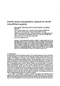
Figure 9. Benchmark images teapot.full, room3 and quake
[6] Z. S. Hakura and A. Gupta. The design and analysis of a cache architecture for texture mapping. In Proceedings of the 24th Internationnal Symposium on Computer Architecture, pages 108–120, 1997. [7] H. Igehy, M. Eldridge, and P. Hanrahan. Parallel texture caching. In 1999 SIGGRAPH/Eurographics Workshop on Graphics Hardware, 1999. [8] H. Igehy, M. Eldridge, and K. Proudfoot. Prefetching in a texture cache architecture. In 1998 SIGGRAPH/Eurographics Workshop on Graphics Hardware, 1998. [9] H. Igehy, G. Stoll, and P. Hanrahan. The design of a parallel graphics inferface. In Computer Graphics (Proceedings SIGGRAPH), 1998. [10] D. Kirk. Unsolved problems and opportunities for highquality, high-performance 3D graphics on a PC platform. In Keynote address in 1998 SIGGRAPH/Eurographics Workshop on Graphics Hardware, 1998. [11] S. Molnar, M. Cox, D. Ellsworth, and H. Fuchs. A sorting classification of parallel rendering. IEEE Computer Graphics and Applications, 14(4):23–32, July 1994.
[12] J. S. Montrym, D. R. Baum, D. L. Dignam, and C. J. Migdal. InfiniteReality : A real-time graphics system,. In Computer Graphics (Proceedings SIGGRAPH), pages 293–302, 1997. [13] A. Vartanian, J.-L. Bechennec, and N. Drach-Temam. Evaluation of high performance multicache parallel texture mapping. In 12th International Conference on Supercomputing, pages 296–303, 1998. [14] A. Vartanian, J.-L. Bechennec, and N. Drach-Temam. Two schemes to improve the performance of a sort-last 3D parallel rendering machine with texture caches. In EuroPar’99, pages 757–760, 1999. [15] A. Vartanian, J.-L. Bechennec, and N. Drach-Temam. The best distribution for a parallel opengl 3D engine with texture caches. Technical Report 1233, LRI, 1999 (http://www.lri.fr/ alex/publis.html). [16] S. Winner, M. Kelley, B. Rivard, and A. Yen. Hardware accelerated rendering of antialiasing using a modified abuffer algorithm. In Computer Graphics (Proceedings SIGGRAPH), pages 307–316, 1997.
�