The DELPHI experiment control system is characterized by a highly decentralized organization: The State Manager Concept processes are distributed over 20 ...
The DELPHI experiment control.
TAdye2), L.Beneteau1), YZ Camporesill, R Chczrpentierl), MD6nszelmunn1), B.Franek2), C.Gaspar1), RGavillet1), A.Grant1), E.LHarris3), Mlonkerll, R.Sekulin2), G.R.Smith2), CERN, CH- 1211 Geneva 23, Switzerland.
Rutherford Appleton Laboratory, Chilton, GB-Didcot OXll OQX, UK. Nuclear Physics Laboratory, University of Oxford, Keble Road, GB- Oxford OX1 3RH, UK.)
The DELPHI detector, which is in operation since the start of LEP in August 1989, consists of 16 different sub-detectors. To provide a high degree of independence to the individual sub—systems, the data acquisition and slow control system has been split into autonomous partitions. The systems which controls the experiment and the subdetector partitions is described.
Introduction
The DELPHI detector [1], a general purpose detector with special emphasis on particle iden tification, is composed of 16 different sub-detectors, which were built by different teams of laboratories of the DELPHI collaboration. To provide a high degree of independence to the individual sub-detectors, the data acquisition and control of the experiment is split into a set of autonomous partitions. Although each detector has its own specific characteristics and function, the organization of these partitions has been standardized up to a high degree. This standardization is extended towards the central readout and trigger. The control of all devices associated with each partition, is organized into so called control domains. There are separate control domains to handle the two aspects of each sub—detector: a) Data-acquisition : i.e. the fastbus embedded readout system [3], and the data iiow handling in the equipment computers [4], and b) Slow-control: i.e. the monitor and control system for technical aspects of the sub-detectors [2] such as gas, volts, pressure, temperature, .... The DELPI·H control systems consists of 18 domains for data acquisition, 17 domains for slow control and a few central control domains. The control domains and their associated driver
processes are distributed over 20 different nodes in the DELPHI online VAX cluster.
The State Manager Concept The DELPHI experiment control system is characterized by a highly decentralized organization: each embedded processor, the equipment computers, and all the tasks running in these computers have a large extent of autonomy. This organization makes the individual components very flexible and maintainable due to their independence. On the other hand it however puts additional strains on the control system. To cope with the complexity of the control a new concept for the coding of the control logic was developed[5][6], with the following design requirements in mind: The system should 1) be able to deal with the distributed nature of the ’driver processes’ (i.e. the processes controlling the external devices); 2) allow for easy modification of the control logic without interference with unrelated driver processes; 3) operate independently from the driver processes and from any interactive run control process. (More specifically, there should
269 OCR Output
bc no logic built into any of thcsc processes); 4) bc ablc to take automatic actions upon changing conditions in thc cxpcrimcnt, indcpcndcnt of any opcrator or intcractivc run control intcrfacc process; and 5) provide concurrent extemal access to a control domain to allow central control domains and a local user interface to access concurrently a local domain.
The approach we adopted is based on the State Manager concept. In this concept, the experiment is described in terms of objects, i.e. logical subsystems, for each of which a number of states are deiined. An object may correspond directly to a concrete entity in the experiment (a computer controlled device) or any abstraction used in describing the experiment provided it can be identiiied by a ’noun’ (e.g. ’run’, ’trigger’,’central detector’, etc.). The control system, which is given by the interaction between the various objects, is specified using a formal language, the State Manager Language (SML). The main characteristic of this language BISZ
Finite state logic. Objects behave as tinite state machines. The only ’variables’ in this language are the states ofthe objects (e.g. RUNNING, PAUSED ,... ). An action applied on an object can bring about a change in its state.
Instruction sequencing. Actions on an abstract object may specify a sequence of instructions, mainly consisting of actions and logical tests on other objects. Actions on concrete objects, are send off as messages to an associated driver process which controls the extemal device.
Asynchronous execution. Several actions may proceed in parallel: an action applied by object-A on object-B, does not suspend the instruction sequence of object—A. Only a test by object-A on the state of object-B suspends the instruction sequence of object-A, if object-B is still in transition. AI like rules. Each object can specify logical conditions based on the state of other objects, which, when satistied, will trigger an action of the local object. This provides the mechanism for an object to respond to unsolicited state changes of its environment.
The logic, specified in the State Manager language is translated by a special compiler to create the State manager. The State Manager runs as an independent process and communicates with its environment using DECNET An interactive control program can be used to control the state manager. This program has access to the specification and states of the objects and may uses this information to dynamically configure its interface.
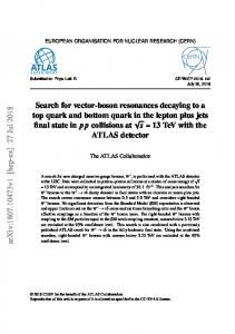
DELPHI Experiment Control Domains To organize the control system of the DELPHI experiment, objects belonging to a specific aspect of the experiment are grouped into an independent State Manager domain (SM-domain). All objects in one SM-domain are managed by their State Manager Process. To coordinate the activities of these individual SM-domains, certain ’abstract’ objects of these domains have been made visible as ’concrete’ objects in the central domains. The following paragraphs describe
the different type of SM-domains participating in the DELPHI experiment control. Each data acquisition partition is controlled by one State Manager. Because of the high degree of standardization, it was possible to write a single package of SML code for all the l8 partitions. There are two main objects in these domains to orchestrate the running of the partition. The OPERATOR object accepts the top level commands (e.g. start.run) from the local operator user interface. The LC object accepts commands from the central control when the partition operates as part of the whole DELPHI detector.
270 OCR Output
` ·—-—- El
obyect 6; LEP domain
==· l t
object
Central ACQ Control wjeet
Xssodated
prg
_ ohjccl ) / ;Associated
°b-l°° yl Wqbjecl
os
"‘1'°° B.2$Z `
Central Slow Control
PIDCSS
?w °”"°‘ Object: LES State: Paused
/ I action: Continue action: End action: Abon
State: Running _ °°’°°`
15*7/ X °"’°°' Md
Local Slow control
Local ACQ control
an JI? €
/ Assmmd_
Bk _
AS°?°d ¤li; `
xsmema Driver
process
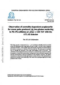
Figure 1: DELPHI experiment control domains. The slow-control domain handles the monitoring and control of technical aspects of a sub—detector. The most important aspect of the slow—¢ontrol domain is the control of the High
Voltage of the gaseous particle detectors. The raising and lowering of these volts have to be coordinated with the status of the LEP accelerator. Uinlike the local data acquisition domains, there is no full standardization in the local slow—control domains. This is mainly due to the
differences in the technical aspects of the individualisub—detectors, such as the requirements on High Voltage control. However, seen from the central control, the individual slow control domains are identical, i.e. they all have a set of identical ’top’ objects with the same states and actions. lntemally these domains are tailored to the environment required by the operation of the specific sub—detector.
The central control logic brings the individual partitions domains together in a coherent
system. By controlling the partition SM-domains, it prepares and supervises the DELPHI detector for global running. There are at present two domains which coordinates the experiment as a whole. The central data acquisition domain qontrols all the detector data acquisition
domains participating in the central run, as well as the central readout control supervisor and the central data logger process. The central slow coritrol domain integrates the partition slow control domains and in particular will provide in the future the interlock between the High Voltage of the detectors with the status of the LEP machine mode. An important aspect at
present being under study is to introduce in the central control the status of the LEP machine. This will allow the central control to take automatic actions triggered by the change of state in LEP machine, such as the automatic end of run and ratnp down of detector high voltages before
LEP prepares a new fill, or the ramp up of detector high voltage and start of run when LEP has
271 OCR Output
finished the preparation of a new Hll and the beam conditions are stable.
Run status and run control interface
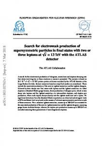
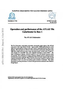
So far only the non interactive aspects of the experiment control system have been described. In theory, such a non interactive system could handle the automatic control of the run. In practice it is necessary to supplement it with interactive tools to monitor and control the experiment by the operator. These tools can also display information which is not taken into account by the mn control logic, e. g. trigger rates, data size ,... ), For this purpose, the Delphi User Interface (DUI) tool[7] has been developed. This graphical interface can access all available information of the experiment using the Distributed Information Manager (DIM) system. Delphi User Interface
The DUI tool allows each operator in DELPHI to set up its own user interface. It merely provides a set of pre—deHned displayable blocks (widget—trees), each of which displays one or more items of the experiment status and control. These blocks are combined, following the specification in the configuration file to form a user interface for a particular application. Many of the blocks use parameters to dynamically (re-)configure themselves (e.g. a block could for instance be read-only or provide a command interface). Each block knows by itself what kind of information to display and how to get it. The configuration file specifies the following standard elements, of which any one can be left out; a menu bar, a pop—up menu, a status area and a work area. The first two are standard MOTIF widgets. The status area shows minimal information of some parts of the experiment control system, either as labels or as pushbuttons. If shown as pushbuttons, a click on them will pop up detailed information. The work area can show one or more detailed blocks. The blocks shown in the status and work area, as well as what pops up if one clicks on a status block, is all defined by the configuration file. Defining new blocks for the DUI system is a three step process. First, the static part of the block is designed in UIL (User Interface Language) or using VUIT (Visual User Interface Tool). Second, a block ’creation’ routine is made to subscribe to the service needed. The same routine
can access parameters of this widget, given in the configuration file, and as such change the structure and or behaviour of the block. It can also take advantage of the information provided by the experiment control system (via DIM) to reconfigure itself. Third and last, an update routine is written to make sure DIM can update the block with the correct information. Since each block is self-contained, any routines belonging to that block will not be executed unless the block is specified in the configuration file. Maintenance of current blocks and introduction of new blocks is done on a block by block basis. So, the DUI system is thus NOT in danger, even if faulty blocks or code are introduced, as long as these blocks are not used in the configuration file.
The DUI system is implemented in C using Xlib, Xtoolkit and Motif routines. UIL is used to specify the static part of the blocks. A parameter system is used as an extension to UIL to make widgets configurable at run time. Apart from the standard Motif widget set two extra widget are used; a matrix widget to display tables of numbers and strings, and a dial widget to display information like trigger rates.
272 OCR Output
31::
Help
TRIGGD L9 Inst. DAQ Status Inst. Rate: DJ? N1
Request. \0\l , VPHV \lA\H.\I \OY`Dh ¤
Ins!. Llvetlmet $8.81 % ‘u~'IN'm°c“ss LEP Genera!
vm qunurv num snow ccnnou.
LEP Manu
LEP Cnrnments
Moda .mi·mi».q cum IDBIUN unlmmw,
s—s:v-ass: was
Tl :**--1 coast na [hi g uysudu
Lzvsquzzzmc
Yntal Current bm] 1382.41 ¤•¤·
n 1 ax an lc v1 ats; umn Huy Q J I nm]
17s.9J 171.uu
Measured Ensrsv [Cov] ·ss.71 ,2 [yn] ¤z.s,7u nux-e td! (G t 0 I b-*1 l. ll n mi [nA) 17-sus vv-s.s=¤
Preuel HD : until · Mnrs.
Next pnyslcs flu mis afmrnoun
separator: [pm] zasmnz I |• [pn] ws.71 mss.-an
1.... ...... EnergyMeasunment Hallrlau-x ,._..;ti_ 1 S UA] 0.00 0.00 mm l S [gm] 0.00 n.u4· FIIIN D
M f +I In ¤¤• un: •s J 17 [M] Mw E no 1 -s h 4 oeunzes Ubmlwm LE7Dat:s
upuae 9-ssv-waz wan °° "
E-Q- ..| nt:) [un] aqua wv u1 mn L- —;
Cummunicttlan ACHVE i ¤uw__Rh! "Ju J9 lb
LD Experimnms
|""'*‘?”‘" Dclphl Status Off I SPS lntcnsnuu [ES)
. L(t) Ildt Bank- Rank- Snlennid Current Exuemn-I
sums
¤ @ ¤~¤¤ E ~~~~¤~~
amusr
Qlazkgmund
Request
LOW
non:
¤+
UM
@
e
UM]
M0
~w\uAL It M w
vetn
(1D" ¢n¤·$-'] [nb'] ground 1 ground 2 [Al
Annu
uwmowx
uxxxowx
¤···¤~·