Sep 23, 1996 - M.Sc. Kari Alho, Helsinki University of Technology. The goal of the thesis is to present ... The focus is on the concepts and the general design,.
HELSINKI UNIVERSITY OF TECHNOLOGY Department of Computer Science Laboratory of Information Processing Science
Casper Lassenius
The Design of the Software Workmate ProcessCentered Software Engineering Environment
Master’s thesis
Supervisor:
Professor
Reijo Sulonen
Instructor:
M.Sc.
Kari Alho
ii
HELSINKI UNIVERSITY OF TECHNOLOGY
ABSTRACT OF THE MASTER’S THESIS
Author and name of the thesis: Casper Lassenius: The Design of the Software Workmate Process-Centered Software Engineering Environment 23.09.1996 86 Date: Number of pages: Department: Professorship: Faculty of Mechanical Engineering, Department Tik-76 of Industrial Management Supervisor: Professor Reijo Sulonen Instructor: M.Sc. Kari Alho, Helsinki University of Technology The goal of the thesis is to present the Software Workmate process-centered software engineering environment. The focus is on the concepts and the general design, but the implementation of the process engine component is also described. The thesis begins with a presentation of the motivations for the work, followed by an overview of the research into the software process: concepts, life-cycle models and modeling formalisms. The discussion on software engineering environments contains requirements, architectures, existing process-centered environments; and issues related to the adoption of software engineering environments and process support technology. The central part of the thesis presents the Software Workmate environment. The conceptual framework it is based upon consists of three principal entity classes: activities, agents and artifacts, and their relationships. The behavior of the entities is described by Finite State Machines. Agents perform activities producing, consuming, modifying and deleting artifacts. The framework is used as a canonical form in order to be able to support process models expressed in different formalisms. The architecture of the system is based on the CORBA standard. The heart of the system is the process engine. Artifacts are stored in artifact servers; the process engine only contains artifact surrogates. Other components in the environment include tool invocation servers, client programs and automated agents carrying out activities intended for automated enactment. The process engine is implemented as a CORBA object. Its interfaces, written in IDL, are described. The last part of the thesis discusses the idealized usage of the environment, evaluates the work, and outlines the future for Software Workmate. Keywords: software engineering, software engineering environment, software process, process support, process modeling
iii
TEKNISKA HÖGSKOLAN
SAMMANDRAG AV DIPLOMARBETET
Författare och arbetets namn: Casper Lassenius Design av Software Workmate: en processorienterad programutvecklingsmiljö 23.09.1996 86 Datum: Antal sidor: Avdelning: Professur: Maskinavdelningen, Utbildningsprogrammet Tik-76 för produktionsekonomi Övervakare: Professor Reijo Sulonen Handledare: DI Kari Alho, Tekniska högskolan Målsättningen med diplomarbetet är att presentera Software Workmate, en processorienterad programutvecklingsmiljö. Huvudvikten har lagts vid koncepten och designen, men implementeringen av processmaskinen beskrivs också. Diplomarbetet börjar med motiveringen till arbetet följd av en översikt av forskningen kring programvaruprocesser: koncept, livscykelsmodeller och modelleringsformalismer. Diskussionen om programutvecklingsmiljöer innehåller krav, arkitekturer, existerande miljöer samt frågor kring ibruktagande av miljöer och teknologi som stöder processer. Arbetets centrala del presenterar miljön Software Workmate. Den konceptuella ramen består av tre entitetsklasser: aktiviteter, agenter och artifakter, samt dessas interna och externa förhållanden. Entiteternas beteende beskrivs med hjälp av finita tillståndsautomater. Agenterna utför aktiviter som producerar, konsumerar, modifierar eller raderar artifakter. Den konceptuella ramen fungerar som en kanonisk form för processmodellering och möjliggör sålunda stöd för modeller uttryckta i olika formalismer. Systemets arkitektur är baserad på CORBA standarden. Miljöns hjärta utgörs av processmaskinen. Artifakterna lagras i artifaktservrar; processmaskinen innehåller endast surrogat. Andra komponenter i systemet är verktygsservrar, klientprogram och automatiska agenter som utför aktiviteter som skall automatiseras. Processmaskinen är implementerad som ett persistent CORBA-objekt. Dess gränssnitt som är definierade i IDL beskrivs. Arbetet avslutas med en diskussion on användningen av miljön, en evaluering av arbetet, samt tankar kring framtiden för Software Workmate. Nyckelord: programutveckling, programutvecklingssystem, programutvecklingsprocess, processtöd, processmodeller
iv
PREFACE This thesis has been written at Helsinki University of Technology as a part of the ProHAKE research project at the Laboratory of Information Processing Science. ProHAKE was a Finnish national research program which aimed at advances in four main areas: process assessment, process modeling, process measurement, and process improvement. The research was carried out by a consortium consisting of Nokia Research Center, the University of Oulu, CCC Software Professionals, VTT Electronics, the Information Technology Development Center (TIEKE) and Helsinki University of Technology. The program was funded by the Technology Development Center of Finland (TEKES) and by the participating companies. At Helsinki University of Technology, the research was concentrated on two areas: assessing and improving the software development process in small companies producing shrink-wrapped software; and developing a framework for process support, including software implementing some of the features of that framework. This thesis is related to the latter. I would like to thank my supervisor, Professor Reijo Sulonen for introducing me to the subject and for his interest in the work. My instructor Kari Alho has been very helpful in scrutinizing the manuscript and his comments have improved the text greatly. A word of thanks also to Kai Risku who has been implementing the process engine component of the system, and whose comments have been very helpful. Pekka Kilponen, who has been working on a client application has also provided valuable feedback on the interfaces.
Otaniemi, 23.09.1996 Casper Lassenius
v
TABLE OF CONTENTS 1 Introduction .................................................................................................................1 1.1 Background .....................................................................................................1 1.1.1 The challenges of Software Engineering................................................1 1.2 Motivation .......................................................................................................3 1.3 Goals and Objectives.......................................................................................3 1.4 Scope ...............................................................................................................4 1.5 Structure of the Thesis.....................................................................................4 2 The Software Process ..................................................................................................5 2.1 Introduction .....................................................................................................5 2.1.1 Approaches to Software Engineering.....................................................5 2.1.2 Product View..........................................................................................5 2.1.3 Process View ..........................................................................................5 2.1.4 Combining the Views.............................................................................6 2.2 Life-cycle Models for Software.......................................................................6 2.2.1 The Waterfall Model ..............................................................................7 2.2.2 The Spiral Model....................................................................................7 2.2.3 Other Approaches...................................................................................8 2.2.4 Pros and Cons.........................................................................................8 2.3 Software Process Engineering.........................................................................9 2.3.1 The Process Cycle ..................................................................................9 2.3.2 Goals of Process Modeling ..................................................................11 2.3.3 Approaches...........................................................................................12 2.3.4 Canonical Form ....................................................................................14 2.4 Process Improvement ....................................................................................14 3 Process-centered Software Engineering Environments............................................17 3.1 Introduction ...................................................................................................17 3.2 CASE Terminology and classification ..........................................................17 3.2.1 Tools.....................................................................................................18 3.2.2 Workbenches........................................................................................18 3.2.3 Environments .......................................................................................18 3.3 Requirements.................................................................................................18 3.3.1 General SEE Requirements..................................................................19 3.3.2 PCSEE-specific Requirements.............................................................22 3.3.3 Requirements for the Software Workmate Environment .....................23 3.4 Architecture...................................................................................................24 3.4.1 APSE ....................................................................................................24 3.4.2 Process-centered Environments ...........................................................25 3.4.3 Distribution ..........................................................................................26 3.4.4 CORBA ................................................................................................26 3.5 Existing Systems ...........................................................................................28 3.5.1 Process-Centered Software Engineering Environments.......................29 3.5.2 Other products ......................................................................................33 3.6 Adoption Issues .............................................................................................34 3.6.1 Benefits of Using CASE Environments ...............................................34 3.6.2 Reasons for the Slow Adoption of CASE Environments.....................35
vi
3.6.3 Solving the Problems ...........................................................................36 4 The Software Workmate Conceptual Framework.....................................................39 4.1 Introduction ...................................................................................................39 4.2 Artifacts.........................................................................................................40 4.2.1 Properties..............................................................................................40 4.2.2 Artifact Servers ....................................................................................41 4.3 Activities .......................................................................................................41 4.3.1 Properties..............................................................................................41 4.3.2 Activity Description .............................................................................42 4.3.3 Execution and Control..........................................................................43 4.3.4 Delegation ............................................................................................44 4.4 Agents............................................................................................................44 4.4.1 Properties..............................................................................................44 4.5 Relationships .................................................................................................45 4.6 Behavior ........................................................................................................46 4.6.1 Artifacts................................................................................................46 4.6.2 Activities ..............................................................................................47 4.6.3 Agents...................................................................................................49 5 The Architecture of the Software Workmate Environment ......................................51 5.1 Introduction ...................................................................................................51 5.2 Object Request Broker ..................................................................................51 5.3 Process Engine ..............................................................................................51 5.4 Artifact Servers .............................................................................................52 5.4.1 File System Server................................................................................52 5.4.2 Configuration Management System .....................................................52 5.4.3 WWW Artifacts ...................................................................................53 5.4.4 Other Artifact Servers ..........................................................................53 5.5 Client Applications........................................................................................53 5.5.1 Process Modeling Clients.....................................................................54 5.5.2 Process Management Clients ...............................................................54 5.5.3 Process Performing Clients ..................................................................54 5.6 Automated Agents.........................................................................................55 5.7 Tools..............................................................................................................55 5.8 Tool Invocation Server..................................................................................55 5.9 OLE Gateway ................................................................................................55 6 Implementation of the Process Engine......................................................................57 6.1 Introduction ...................................................................................................57 6.2 Architecture...................................................................................................57 6.2.1 CORBA Interface .................................................................................57 6.2.2 Interface Implementation Classes.........................................................58 6.2.3 Database Classes and the Object Database ..........................................58 6.3 Interfaces .......................................................................................................58 6.3.1 PSSObject ............................................................................................59 6.3.2 HasACL................................................................................................61 6.3.3 PE .........................................................................................................62 6.3.4 Project...................................................................................................63 6.3.5 Agent ....................................................................................................63 6.3.6 AutoAgent ............................................................................................65 vii
6.3.7 Group....................................................................................................65 6.3.8 Role ......................................................................................................66 6.3.9 FSM......................................................................................................66 6.3.10 UsesFSM ............................................................................................67 6.3.11 Activity...............................................................................................67 6.3.12 AgentBinding .....................................................................................69 6.3.13 Artifact ...............................................................................................69 7 Using Software Workmate ........................................................................................73 7.1 The Framework Builder ................................................................................73 7.2 Tool Vendor/Writer.......................................................................................73 7.3 SEE Customizer ............................................................................................74 7.4 Process Engineer ...........................................................................................74 7.5 Software Development Manager...................................................................74 7.6 Software Developer.......................................................................................75 7.7 SEE Administrator ........................................................................................75 8 Discussion and Future Plans .....................................................................................77 8.1 Introduction ...................................................................................................77 8.2 Evaluation Against the Original Requirements.............................................77 8.2.1 Multiple Formalism Support ................................................................77 8.2.2 Support for Change in the Process .......................................................77 8.2.3 Artifact Support....................................................................................78 8.2.4 Process Support ....................................................................................78 8.2.5 Multiple Simultaneous Users and Group Coordination .......................79 8.2.6 Distribution of Artifacts, Agents and Activities...................................79 8.2.7 Importing Existing Tools .....................................................................79 8.3 Future Directions...........................................................................................80 8.3.1 Process Engine .....................................................................................80 8.3.2 Clients ..................................................................................................80 8.3.3 Artifact Servers ....................................................................................80 8.3.4 Automated Agents................................................................................80 9 Conclusions ...............................................................................................................81
viii
1 INTRODUCTION 1.1 Background 1.1.1 The challenges of Software Engineering Modern society in the developed countries is in many ways dependent on software, that is, computer programs, procedures, and possibly associated documentation and data pertaining to the operation of a computer system [IEEE91]. Most businesses rely on computer systems carrying out many tasks, from product development and production control to ordering, logistics and invoice systems. Banks and credit card companies have large, globally distributed databases containing the data needed for everyday operations. More and more of the products that people use every day, like toasters, washing machines, cellular phones, calculators, airplanes and anesthesia instruments have much of their functionality in software. Malfunction in some critical part of the software might even lead to loss of human lives. It is clear that producing high-quality software in as efficient a manner as possible, on time and within the budget, is a key concern of many companies, and also of utmost importance for the smooth running of society in the post-industrial world. A Historical Perspective The field of software production is very young compared with other engineering fields. At the beginning of the computer era, i.e., in the 1950s, a piece of software was typically developed by one programmer or by very small teams [Somm96]. The enduser was often the programmer himself. As the capacity of computers increased enormously, so did the expectations and the needs for more sophisticated software products. Increased complexity lead to bigger and more complex programs which could no longer be developed by single programmers or very small teams. This meant larger teams working on the same piece of software, which, in turn introduced many new problems with, e.g., modularization and coordination of the work. Also, new problems with understanding and communicating requirements emerged as the endusers no longer wrote their own programs. Making complex software was indeed very hard, and using bigger teams was not at all as easy as was first believed. The term software crisis was invented to describe the situation. Symptoms of the crisis include [BrEa92, Somm96] :
• software projects often run late and deliver products with poor quality • software costs are perceived as unpredictable, and they are often excessive. • delivered computer systems do not meet the needs of the users, • software fails, • software maintenance is hard, expensive, and error-prone, • software migration from one system to another is seldom possible
1
In order to solve the crisis, it was recognized that software production should be approached in an orderly way, similar to the way other products were developed. The term software engineering was invented in the 1960s. The term can be defined as the application of a systematic, disciplined, quantifiable approach to the development, operation, and maintenance of software, that is, the application of engineering to software [IEEE91]. The Situation Today We have now come a long way since the 1960s and the invention of the terms software crisis and software engineering. A great deal of effort has gone into finding the reasons behind the symptoms and solving the problems. New programming languages, methodologies and tools have been invented and used. The idea that computers and computer software can aid in software engineering led to the development of CASE, or Computer Aided Software Engineering. Today, we have much more powerful computers, more advanced programming languages, sophisticated tools for supporting different tasks in software development and a lot more knowledge about software production than thirty years ago. The fact is, however, that we still are faced with many of the same problems that existed in the 60s. It is still not unusual for a software project to be late, or to for the product to contain errors. There is a multitude of examples. A recent incident that received a great deal of attention in the media was the result reporting system for the 1996 Olympic Games in Atlanta. Promoted as one of the most advanced and modern systems in the world, the expectations were very high. Unfortunately, the system did not work as expected: the results from the competitions were late or not at all available. [Hufv96]. Future Prospects How can it be, that we still are not able to deliver high-quality software within the promised budgets and time? In a famous article from 1986, entitled “No Silver Bullet — Essence and Accident of Software Engineering”, reprinted and commented on in [Broo95], professor Fred Brooks argues that “there will be no one single development, in either technology or management, which by itself promises even one order-ofmagnitude improvement within a decade, in productivity, in reliability, in simplicity.” His motivation for this claim is that it is the essence of software, i.e., its complexity, conformity, changeability and invisibility that causes the problems we have, and not the accidental properties that have been addressed by the new languages and approaches that have been developed during the past thirty years. Now, in 1996, it seems that Brooks was right. This does not, of course, mean that it is useless to develop new techniques and methodologies for software engineering. The important message is that no single technology or technique will be perfect, but that, instead of looking for silver bullets, we need to understand that improvement will come in an evolutionary way instead of radically. One could compare this notion of incremental improvement with the Kaizen way of improving business and manufacturing processes, as opposed to radical changes in business processes like business process reengineering. Using total quality management (TQM) and Kaizen principles [Feig91], many businesses have made significant improvements in their processes,
2
over time. The same can be seen in the software engineering world. In other words, research into software engineering certainly pays off. The problem is that we should recognize that the path is long and hard, and that improvements will not come over night. This is usually hard for companies in the Western culture, and especially in the USA, since short-term goals and profits are often considered more important than long-term investments and improvement undertakings. This is something that has to change if we really want to get good at producing software, which is critically important as society grows even more dependent on software and the demand for more complex and high-quality software continues to increase.
1.2 Motivation The motivation for this work stems from the general observations above, from our belief in the gains of supporting software development with computers, and from some observations on existing process-centered software engineering environments. Currently, several process-centered environments have been developed. Most of them are research prototypes, but at least two systems are commercially available. The adoption of this new technology has, however, been very slow. It is our belief that the existing systems suffer from some inherent limitations, e.g.:
• they are built around one specific process modeling formalism, • they provide limited support for process evolution, • they provide limited support for artifacts stored in different servers. 1.3 Goals and Objectives Based upon the above observations and opinions, we set out to design and build a process-centered environment with the goals of solving some of the problems mentioned. Issues that we were especially interested in were multiple formalism support and process change support. These, as well as other requirements are presented in more detail in Chapter 3. The results of the work so far, have been the design of the environment, which we call Software Workmate, and a partial implementation of one of the most central components, called the process engine. Some client applications for the environment have also been developed. The goal of this thesis is to document the Software Workmate Software engineering environment: the motivation, the concepts and the implementation. Specific objectives are to present motivation for the work, the concepts underlying the system, the requirements on the Software Workmate Environment, and its architecture. The implementation of the process engine component of the system, and how the environment could be used will also be discussed. A final objective is to evaluate the system, identifying its strength and weaknesses and to present plans for its future development.
3
1.4 Scope The environment designed in this thesis is limited to having only one process engine. Extensions providing process engine to process engine communication could be added, but are not described in this work. The issues of artifact support and automated enaction are very complex, and are described only to the level we have understood and designed them at the time of this writing. In addition to the process engine, we have implemented some additional components. These are only touched upon in this thesis, and not discussed in any depth.
1.5 Structure of the Thesis The rest of this thesis is structured in the following way: Chapter 2 discusses the software development process: life-cycle models of it, and an emerging discipline called software process engineering. This chapter provides motivation for developing process-centered software engineering environments as well as provides the reader with sufficient conceptual background for understanding the rest of the text. Chapter 3 contains a brief discussion on process-centered software engineering environments. First, a terminology and classification for CASE is presented. Then, requirements for software engineering environments in general, and process-centered environments in particular are presented. Following this, the requirements for the Software Workmate Environment are discussed. An overview of some architectural issues for process-centered software engineering environments and a short discussion of existing systems follows. The chapter concludes with a discussion of issues related to the adoption of process technology in companies. Chapter 4 presents the conceptual framework for the Software Workmate environment. The concepts of the framework are discussed first, followed by more detailed description of the entities and relationships that comprise the framework. Chapter 5 describes the architecture of Software Workmate. First, a general overview is given. Then, each component of the architecture is discussed in greater detail. Chapter 6 reports on our experiences in implementing the Process Engine component of the environment. The implementation is discussed up until the application program interface (API) level of the process engine. Chapter 7 describes how the Software Workmate environment could be used from the perspective of different users. Chapter 8 evaluates the work and discusses the future plans for Software Workmate. Chapter 9 ends the thesis with some final conclusions.
4
2 THE SOFTWARE PROCESS 2.1 Introduction This chapter discusses the software development process and issues related to understanding and documenting it. First, life-cycle models of the software process are presented, and their merits and drawbacks discussed. Then, an emerging discipline called software process engineering is presented. This chapter provides motivation for developing process-centered software engineering environments as well as provides the reader with sufficient conceptual background for understanding the rest of the text. 2.1.1 Approaches to Software Engineering There are basically two approaches to solving the problems of software engineering. One approach is to look at software development from the product point of view, and the other is to view the problems from the point of view of the development process, often referred to by the term software process. 2.1.2 Product View From the product point of view, software engineering creates, modifies, evolves or maintains a complex product. The product can be thought of as a complex compound artifact, whose components evolve individually. New components may be added or deleted. There are lots of different relationships between the components, both structural and semantic that need to be modeled and understood. The product point of view is represented, e.g., by the areas of product modeling and configuration management. From the product point of view, the process is implicit, i.e., it is understood that some work needs to be done in order to create and modify the product, but the process is not explicitly modeled. 2.1.3 Process View Software development, when viewed from a process perspective, is a set of steps — possibly partially ordered — that produce or modify a software product. From this point of view, the process is described explicitly through some formal or semi-formal process model, and the product is typically not modeled in detail. The process models typically consist of some basic process elements and their relationships. The most typical elements found in most process models are activities, agents and artifacts. There are currently no generally agreed upon definitions for these terms, or for any other terms used in the process models, but their intuitive meaning should be quite clear: Agents are the humans or computers carrying out activities that change, delete and produce artifacts. Often, the agents can perform activities in different roles, e.g. “programmer”1.
1
The terms are deliberately introduced informally in order to ease the understanding of the following discussion.
5
Other terms are also sometimes used, e.g. tasks or process elements may correspond to activities. The terms used in the Software Workmate software engineering environment are defined in Chapter 4. Attempts have been made at standardizing the terminology, e.g., in [FeHu89, Long89], but they do not seem to have got the attention they should have deserved. There also seems to be some confusion around very basic terms, a fact which, e.g., Kontio has noted and discussed [Kont96]. 2.1.4 Combining the Views Both the product centered and the process-centered approaches have their merits, and they are often combined in some ways. For example, many organizations view software production at a high level as a sequential process, but inside the steps, the approaches are more product oriented. The combination of the approaches is natural, since there is no product without a process that produces it, and conversely no (meaningful) software process that does not produce or maintain a product2. This dualism between the product and the process perspective has not been much looked into until the recent interest for software process modeling and processcentered software development environments. In order to support actual software development processes, process-centered environments need good models of both the software product being developed and the process used to develop the product. Thus, it seems that the development of such environments is a natural place to further explore this dualism between the product and process view of software engineering. Computer systems providing process guidance and execution support are known as process-centered software engineering environments, and are the focus of this thesis. In order to support a process, there has to exist a formal model which is tailored to the specific project that should be supported. This idea was first proposed by Osterweil in his seminal paper “Software Processes are Software too” [Oste87], where he argues that the software development process could be programmed using the same kind of approach used when writing ordinary programs. This paper got lots of critique, e.g. [Lehm87, Lehm88], but it also inspired a lot of new research around process-centered environments.
2.2 Life-cycle Models for Software The first attempts at modeling and understanding the software process viewed it at a very high level of abstraction. These so called life-cycle models have been generally accepted, and are widely used in organizations that produce software. The idea behind the life-cycle models was to model how software should be produced, i.e. they are prescriptive. Today, it is recognized that there are different ways of producing different kinds of software, and that there is no single life-cycle model that suits all needs. The high level of abstraction in the life-cycle models also limit their usefulness in actually supporting and helping software development.
2
E.g. management processes do not directly produce software products, but they exist only in order to support processes producing or maintaining software (big organizations might have superfluous management processes, but that is out of the scope of this thesis).
6
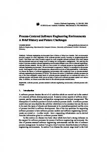
2.2.1 The Waterfall Model The first widely accepted model was the so called waterfall model, presented by Royce [Royc70], and which was derived from other engineering process models. The waterfall model views software production as a sequential process, with each step delivering some documents or products needed in the next phase. A version of the waterfall model is depicted in Figure 2-1 below.
Requirements definition
System and software design
Implementation and unit testing
Integration and system testing
Operation and maintenance
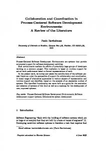
Figure 2-1: The waterfall model Even though the waterfall model is the most well known and widely used life-cycle model, it is often criticized for various reasons. It is nowadays, e.g., recognized that software engineering is an inherently parallel activity, which is not reflected in the waterfall model. General critique of life cycle models is presented in section 2.2.4 below. 2.2.2 The Spiral Model A newer life-cycle model known as the spiral model, and shown in Figure 2-2, was introduced by Boehm in 1988 [Boeh88]. The spiral model explicitly recognizes the risks of software development. The spiral model is very flexible, and has no fixed phases. Instead, the model prescribes a four-step loop that should be executed as many times as needed. The first round could concern the requirements, the second the design of the software etc. In each loop, there following steps should be taken: 1. Objective setting: the objectives for the phase are defined, and the risks are identified;
7
2. Risk assessment and reduction: the risks that are identified are assessed, and steps are taken to reduce them; 3. Development and validation: a development model is chosen and carried out, and the product is verified; 4. Planning: the next loop (if needed) is planned, and the next loop is then started from step 1.
Determine objectives alternatives, contraints
Evaluate alternatives identify, resolve risks Risk analysis Risk analysis Risk analysis
Prototype 3
Operational prototype
Prototype 2 ProtoREVIEW Risk analysis type 1 Requirements plan Life-cycle plan Concept of Operation
Simulations, models, benchmarks S/W requirements
Product design
Development plan Requirement validation
Detailed design
Code
Plan next phase
Integration and test plan
Design V&V Acceptance Service test
Unit test Integration test Develop, verify next-level product
Figure 2-2: The spiral model The spiral model does, in a sense, propose an iterative way of producing software, i.e., evolving it. If the whole process is completed in only one round of the model, the spiral model resembles a risk-aware waterfall model. 2.2.3 Other Approaches There are also other approaches to software development at the life-cycle level. Examples include evolutionary development [BaTu75], formal transformations [Balz81] and reuse-oriented software development. These approaches, though they have important applications, seem not to have become as popular as the waterfall or spiral models. They do exhibit many of the same strengths and weaknesses as the more popular models. As the purpose is to introduce the reader to life-cycle models, and not to describe them into much detail, these other approaches are not discussed any further. 2.2.4 Pros and Cons The main merits of the life-cycle models of the software process are that they have made us aware of the software process and provided a global view of the main activi-
8
ties of software production and their relationships. They do not, however, include process information to the level of detail needed to successfully run software projects. Details not contained in the life-cycle models include: [Madh91]
• triggering and terminating conditions of an activity, • the state of a product component before and after an activity, • tools needed in different process steps, • the inputs and outputs of an activity, • the data flow between activities, • the roles played by the people in the process, • the constraints on the process, • how communication should be supported, and • where parallel and sequential steps exist. The list does not necessarily apply as such to all life-cycle models, e.g., high-level inputs and outputs are sometimes added to the waterfall model. The point should still be clear — that life-cycle models are not good enough for really documenting good software engineering practices. In order to overcome the deficiencies in the life-cycle models of the software process, more detailed descriptions that accurately capture different properties of the real-world process have to be developed. This is the goal of a new discipline, which Madhavji calls software process engineering [Madh91].
2.3 Software Process Engineering 2.3.1 The Process Cycle Madhavji’s process cycle [Madh91] presents the main ideas of process engineering at a high level and in a way that is easy to grasp. The process cycle, shown in Figure 2-3 below, consists of three sectors labeled A, B and C. Together these sectors define the scope of the total set of process steps necessary for the development and evolution of software processes. Engineering Process Models The process engineering work starts in sector A, where process engineers design, construct and improve generic process models, i.e., models that are not tailored to any goals of a specific project but are more general in nature. Different process models may be developed for different kinds of projects, e.g., one model for risky projects and another one for mission critical applications. The project free goals and policies concern the process of developing process models, often called the meta-process, i.e. how the process models are developed. The development of process model is assisted by process engineering tools.
9
Managing Software Processes
E CI LI O
ERS INE G EN
S
PRO CE SS
AN D
OA LS
IES
MANAGERS
ER
TO O L S
INE
PROCESS DESCRIPTIONS
POLIC
IN G
EN G
AND
AG
PROCESS FEEDBACK
P R OCE S S
B LS
IN
E
AN
PROCESS
OC
A GO
RE EG
PR
LS
M
C T -F
T C FI CI
G
O TO
SS
PROJE
OJ EC
PE
A
PR
-S
P
Sector B shows process managers adopting and customizing the generic models for use in specific projects. The process managers take project-specific goals into consideration and use process managing tools in their work. The customized process models are then instantiated with project-specific parameters like, e.g., schedule and resources. Finally, the instantiated process models are released for interpretation, by humans, computers or both, thereby enacting the software process.
ENACTED PROCESS
PR
AP
PR OC ES S PL IC AT I ON
OC
SO F
ESS
P E R F O R MI N G
TW A R
TO
A E- S P E C I F IC G O
OL
S
RS ME R FO S IE PER IC L PO ND LS A
C Figure 2-3: The Process Cycle [Madh91] The process managers also have to identify trouble spots during process enaction, and isolate and fix the problems dynamically without disturbing the other parts of the process. The process engineering tools in sector A deal with generic descriptions within a simulated environment, whereas the tools in sector B work on specific descriptions within both simulated and actual environments. Changes to the process are much easier to introduce in section A, since they do not immediately affect any ongoing project.
10
Performing the Software Process The process performers, i.e., the software engineers shown in sector C carry out, or enact, the software process when developing the software. This is depicted by the arrow pointing from the enacted software process to the process performing tools, which assist the software developers in their work. Feedback A very important aspect of the process cycle is the feedback among the different sectors shown in the picture. Process performers generate feedback which is passed on to project-specific process managers. Feedback can also be automatically generated by process management tools. The process managers can then use the feedback to improve the specific process, or make generalizations about possible improvements to the generic models developed in sector A. The generalizations are finally given to the process engineers in order to get the changes incorporated into the generic models. This feedback cycle is continuous. Madhavji also notes that it is possible that the roles of process engineer, process manager and process performer can be divided in several ways between the people in an organization. One possibility is to have different organizations or persons for each role. The other extreme would be to have one single person act in all three roles for some part of the software process. In between these two extremes, there are lots of room for variations. The process cycle should not be understood as imposing an organizational structure, it merely tries to identify the roles involved. As discussed above, the process cycle starts by process engineers making generic process models of the software process. In order to do this, they have to use some kind of process modeling formalism. There are currently a lot of process modeling formalisms, as we will see later on, but many of them are not capable of capturing the process to the level needed for enaction (either human or automated) of the process. Indeed, there can be lots of other goals for making process models than for enaction support. These diverse goals of software process modeling are discussed next. 2.3.2 Goals of Process Modeling There can be several different reasons for making models of software processes, and different organizations have different reasons for initiating process modeling efforts. The following list of goals and objectives for process modeling is included in [CuKO92]: 1. facilitate human understanding and communication: represent the process in a form understandable by humans, enable communication about and agreement on the software process, formalize the process so that people can work together more effectively, provide sufficient information to allow an individual or team to perform the intended process, and form a basis for training the intended process; 2. support process improvement: identify all necessary components of a highyield software development or maintenance process, reuse well-defined and effective software processes, compare alternative software processes, estimate the impacts of potential changes to a software process without first
11
putting them into actual practice, assist in the selection and incorporation of technology into a process, facilitate organizational learning regarding effective software processes, and support managed evolution of a process; 3. support process management: develop a project-specific software process to accommodate the attributes of a particular project, such as its product, or organizational environment, reason about attributes of software creation or evolution, support development of plans for the project, monitor, manage and coordinate the process, and provide a basis for process measurement; 4. provide automated guidance in performing process: define an effective software development environment, provide guidance, suggestions and reference material to facilitate human performance of the intended process, retain reusable process representations in a repository; 5. provide automated execution support: automate portions of the process, support cooperative work among individuals and teams by automating the process, automatically collect measurement data reflecting actual experience with a process, and enforce rules to ensure process integrity. This list could be viewed as containing a spectrum for goals of modeling, from the easiest goal (number 1) that sets the least requirements on the formalisms used to the ambitious goal of automatically supporting a software process by computers. Today, most organizations seem to be interested mostly in the first two objectives, i.e., facilitation of human understanding and communication, and support for process improvement. An interesting thing is, however, that the majority of the research in the area has focused on the last two objectives. This has led to a wide gap between the state-of-the practice in the software industry, and the state-of-the art in universities and other research centers regarding process modeling [SoRo96]. This fact is further discussed in the next chapter. 2.3.3 Approaches The diverse goals on process modeling are reflected in the many different process modeling formalisms that exist today. The formalisms range from simple, “semiformal” graphical notations to comprehensive textual “process programming languages”. The simpler, graphical formalisms are more typically used for informally documenting a process in the interest of human understanding and improved communication. The textual, more comprehensive formalisms are typically used when working with computerized support of the process. Table 2-1 lists language types and constructs that have been used in process modeling. The right hand column is by no means comprehensive, and is included for illustration purposes only. The ISPW-6 Benchmark Process In order to ease the comparison of different process modeling formalisms, a standard benchmark has been developed [Kell91b]. Known as the ISPW-6 process example, the benchmark includes many carefully chosen aspects of a real world process, such as iteration, different media for communication, creative activities and decision points requiring professional judgment.
12
Base Language Types and Constructs Procedural programming languages Systems analysis and design3 AI languages and approaches4 Events and triggers State transition and Petri-nets Control flow Functional languages Formal languages Data modeling5 Object modeling6 Precedence networks7 Quantitative modeling
Sample Software Process Modeling Approaches APPL/A Statemate AP5, Grapple, Marvel, MVP-L AP5, APPL/A, Statemate Role Interaction nets, Spade, Statemate MVP-L HFSP Context-free grammar APPL/A, PMDB, Statemate AP5, Marvel, MVP-L SPMS Systems dynamics
Table 2-1. Language Types and Constructs Used as Bases for Software Process Modeling [CuKO92] The process example concerns a small fragment of the software change process; more specifically the designing, coding, unit testing and management of a localized change to a software system. The change is prompted by changed requirements, and occurs late in the development cycle. The process starts with the project manager scheduling the change and assigning the work to appropriate staff, and ends when the new changed version of the software has successfully passed the unit tests. The core problem has been simplified by stating, e.g., that there are no resource constraints. This, and other issues, such as several simultaneous changes to the product, and process change have been addressed in extensions to the problem. There are a vast number of solutions to the problem, and it has also been extended a number of times. Comparisons of different process modeling formalisms can be found, e.g., in [ArBa92, CoLi93]. Despite the large number of existing formalisms, it has been pointed out that there is no single language or formalism capable of correctly and thoroughly representing all parts of a real-life software process [ArKe94]. There is a need for multiple-paradigm process modeling, i.e., the intelligent combination of existing formalisms. [Kell91a, ArKe94]. The process example has been criticized for not being representative and not taking organizational and human factors into consideration, even though they are critical for the successful adoption of process technology. They also set requirements on the process modeling formalisms, like need to distinguish between the procedural and non-procedural process fragments, and the possibility to model communication and coordination between humans [SoRo96].
3
including DFD,SADT, structure charts including rules and pre-/post conditions 5 including E/R, relations, structured data declarations 6 including class types and instances, hierarchy, inheritance 7 including PERT and critical path method (CPM) 4
13
Process Perspectives When combining different formalisms, it can be helpful to look at the process from different points of view. Curtis et. al. [CuKO92] propose that we can view the process from four different perspectives: 1. the functional perspective, representing what process elements are performed, and what flows of information are relevant to these process elements, 2. the behavioral perspective, representing when process elements are performed, as well as how they are performed, 3. the organizational perspective, representing where, and by whom in the organization process elements are performed, and 4. the informational perspective, representing the informational entities produced or manipulated by a process. The process can then be modeled using, e.g., one formalism per perspective. Problems with consistency and completeness do naturally arise when using multiple paradigms in this way, since the views are not completely orthogonal. These problems can be helped by using tools which support the formalisms used. These perspectives are not the only possible ones, as pointed out by Kontio [Kont95], who also suggests other possible perspectives. He does, however, agree that these perspectives are among the most important ones. 2.3.4 Canonical Form When modeling a process using a multiple-paradigm approach, a canonical form for process modeling would provide a way of combining the notations. It has been suggested that such a form should be developed [CuKO92, ArKe94]. There are several arguments in favor of a canonical form. With a canonical form, it is also easier to translate from one formalism to another. Without a canonical form, the translation between n languages requires n*(n-1) translators, whereas a canonical form reduces the need for translators to 2n. Some experiences with translation between different process modeling formalisms exist, e.g. [Hein93]. A canonical form is also a possible way of storing data in a processcentered software engineering environment. This idea is utilized in the Software Workmate Environment described later in this thesis.
2.4 Process Improvement As mentioned earlier, many organizations are currently working on improving their software processes. This movement is, at least to some degree, due to the Capability Maturity Model, CMM [PaCC93], developed at the Software Engineering Institute at Carnegie-Mellon University. The CMM classifies software processes into five maturity levels and prescribes a path for getting from the lower (worse, more immature) levels to the higher (better, more mature) levels. The CMM is, in a sense, a reference model, i.e., an idealized, high-level model of what a good software process should contain, and how the supporting organization should work.
14
The CMM improvement path starts by assessing the current process and organization to find out at which maturity level it is, and which its weak points are. The improvement then proceeds according to the CMM. Other process improvement methods include the Quality Improvement Paradigm (QIP) and the Experience Factory concept developed at University of Maryland [Basi93]. A new international standard, known as SPICE, which stands for Software Process Improvement and Capability dEtermination [Dorl93], is also being developed. One of the great hopes of the proponents of process-centered software engineering environments is that they will be useful in software process improvement. The maturity models are, due both to their high level of abstraction and generality, not suitable as such for inclusion into process-centered software engineering environments. They might, on the other hand, be used as a basis for development of more detailed, organization specific models that could be used by such environments.
15
16
3 PROCESS-CENTERED SOFTWARE ENGINEERING ENVIRONMENTS 3.1 Introduction As discussed in the last chapter, the idea of using a process model to guide and automate a software process is one of the main goals of process engineering. In this chapter, we discuss software designed to do this, i.e., process-centered software engineering environments. The next section lays the basis for the rest of the chapter by defining the concepts of tools, workbenches and environments. Section 3.3. discusses requirements for process-centered software engineering environments and presents the requirements for the environment presented in later chapters. Section 3.4. discusses architectural issues, and Section 3.5. presents a brief overview of existing process-centered environments. Finally, Section 3.6. discusses issues related to the adoption of CASE environments and process support technology.
3.2 CASE Terminology and classification Process-centered software engineering environments belong to a group of systems called CASE systems. (Computer-Aided Software Engineering systems). Computeraided software engineering can be defined as the use of computers to aid in the software engineering process. May include the application of software tools to software design, requirements tracing, code production, testing, document generation, and other software engineering activities. [IEEE91] This definition is very broad, and it does very well reflects the current situation, where almost anything from editors and compilers to complete software engineering environments are marketed as CASE tools. Under the CASE umbrella, there exist a lot of terms, many very close to each other. In order to grasp the field and intelligently discuss issues related to it, the technology—both existing and future—has to be classified in some way. There are several ways of doing this, e.g., according to which part of the software process the tools support (e.g. design tools, testing tools), or what kind of functionality they offer (e.g. configuration management tools, editors). In this thesis, I use a classification proposed by Fuggetta, which seems to have gained some acceptance in the software engineering community. In [Fugg93], Fuggetta classifies CASE products in three categories according to the breadth of support for the software process: 1. Tools support only specific tasks8 in the software process, e.g. compiling or editing, 2. Workbenches support one or a few activities, e.g. design or coding, and 3. Environments support (a large part of) the software process.
8
The software process is understood to consist of elementary tasks like compiling and editing, which can be combined into activities.
17
3.2.1 Tools Tools support specific tasks in the software process. Tool classes include editing, programming, verification & validation, configuration management, metrics & measurement and project management tools. Each of the tool classes can be divided futher. E.g. the configuration management tool class includes configuration- and versionmanagement tools, configuration builders, change-control monitors and librarians. 3.2.2 Workbenches Workbenches are integrated applications that support specific software process activities. Workbenches typically provide a homogenous user-interface, easy invocation of different tools and access to a common, centralized data set. These features correspond to presentation integration, control integration and data integration discussed in section 3.3.1. Examples of workbenches include analysis & design workbenches (sometimes referred to as “upper” CASE), programming workbenches and configuration management workbenches. 3.2.3 Environments9 CASE Environments are collections of tools and workbenches which provide support for the whole, or large parts of, the software process. Fuggetta divides environments into toolkits, language centered environments, integrated environments, fourth generation environments and process-centered environments. Process-centered environments are distinguished from the other environments by the fact that they automate, guide and/or enforce a specific software process according to a formal model of the process. The process-centered environments include a component called the process engine, which interprets the process model and automates process fragments, invokes tools, enforces policies etc. Process-centered environments typically handle two separate functions: process model production and enactment.
3.3 Requirements Software engineering environments have many different classes of users, from tool vendors to software developments managers, system administrators and application software developers. All groups of users have their own interests and requirements on an environment. This means that analyzing requirements for a software engineering environment is a very complex task, with many possibly conflicting requirements. One could believe that the one reason for the slow adoption of software engineering environments in companies is that this task has not yet been carried out successfully. Issues related to adoption of software engineering environment technology is further discussed in Section 3.6.
9
CASE Environments are often referred to under different terms that are very close to each other. A recent trend (e.g. [ECMA91, BrEa92, Fugg93] is to ignore the small differences in the definitions and treat the following terms as synonyms to CASE Environment: Software Engineering Environment (SEE), Integrated Project Support Environment (IPSE), Integrated Software Engineering Environment (ISEE), Software Development Environment (SDE), and Integrated Software Factory (ISF). In this thesis, I use the terms Software Engineering Environment (SEE) and Process-centered Software Engineering Environment (PCSEE).
18
This section briefly discusses general requirements for software engineering environments from the point of view of different users. First general requirements for software engineering environments are discussed followed by some additional requirements on process-centered environments. Finally the requirements for the Software Workmate environment are presented. 3.3.1 General SEE Requirements According to Brown et. al. [BrEa92] it can be useful to view requirements for a software engineering environment from the point of view of different users of the system. In order to do this they present a simplified life-cycle model for software engineering environments shown in Figure 2-1. The steps are quite intuitive: first the framework builder builds a CASE framework consisting of the basic services the system provides. Then the system is populated, i.e., tools are added. This task is typically performed by tool vendors or by the CASE framework provider himself. The third step consists of customizing the environment to the needs of the organization going to use the environment. Finally the system is used by the software developers. 1. Framework
2. Population
3. Customization
4. Use
SEE framework builder
Tool vendor/ writer
SEE customizer
Software developer
Software development manager
SEE administrator
Figure 3-1: A simplified SEE life-cycle model [BrEa92] These different users have different, sometimes contradictory requirements on the software engineering environment. Brown et. al. list the following:
• framework builder: provide appropriate services and make them accessible to tool writers, provide integration capabilities for tools, take industry standards into account, take a flexible approach to tool support;
• tool vendor/writer: services provided should be the ones most needed and be easily accessible, the SEE should not impose too much performance penalties, mechanisms for inter-tool communication are provided, SEE is popular and widely used, conforms to standards (present and future), is up-to-date with the latest technology, flexible and provides a measure for consistency;
• SEE customizer/environment builder: the framework services are generic and tailorable, the framework allows locally developed tools to be integrated, has a
19
flexible approach to user interface design, allows different software engineering approaches to be used, and can support the managerial, communication and organizational procedures used in the organization;
• software application developer: the SEE is robust and easy to use, provides help with routine tasks, does not hinder creativity, permits personal tailoring of tools and encourages and supports skills that are of long term benefit to the individual;
• software development manager: there is documented benefit of the use of the SEE, there is a well documented and tested method for introducing the SEE into the organization, there is a well-defined migration path from the current methods to the intended use of the SEE, the SEE conforms to present and future standards, integrates well with the tools that already are in use, make software development more cost-effective, more predictable and the process more visible and thereby more manageable;
• SEE administrator: the SEE exposes the data and process definitions and allows them to be updated, allows tuning to different loads, performance requirements etc., provides appropriate security, privacy, recovery and archiving mechanisms, provides metrics and measurement tools, is sensitive to the problems of installing and maintaining a large, complex piece of software. As can be seen, even at this very high level of abstraction, the list of requirements is very long, and it can of course be extended almost ad infinitum. From each of these high-level requirements several technical requirements can be derived. A derivation of this kind is out of the scope of this thesis, the list has been used like a checklist in order to remember the different kinds of SEE users when deriving the requirements for the Software Workmate Environment. Integration A technical issue that can be read between the lines in the requirements presented above, is the need for integration in software engineering environments. Historically, software engineering environments consisted of collections of tools that typically were not able to inter-operate [Somm96]. The importance of providing coherent, integrated environments is well known today. According to [ECMA91], there are five different kinds of integration in software engineering environments. These are 1. Platform integration (framework integration); the tools and workbenches run on the same platform, i.e., the same computer or computer network, possibly consisting of different kinds of computers running different operating systems. 2. Data integration; the tools and workbenches can exchange data. This can be accomplished, e.g., through shared files, shared data structures or through a common, shared data repository. 3. Presentation integration; the tools and workbenches have a common way of interacting with the user. There are three levels of presentation integra-
20
tion: window system integration, command integration, and interaction integration. 4. Control integration; tools and workbenches can control the activation of other components in the environment. 5. Process integration; the environment has knowledge of the process to be performed and can use that knowledge to schedule tasks, automatically invoke tools, guide the users and enforce conformance to the process. A well integrated system should provide all five kinds of integration. On the other hand, it is also widely recognized that systems need to be open, i.e., allow users to easily “plug in” their own tools into the environment. This is an issue related to both control and data integration. The NIST/ECMA Reference Model A more technical view of the requirements for a software engineering environment is given in the Reference Model for Software Engineering environments jointly developed by the National Institute of Standards and Technology (NIST) in the USA and the European Computer Manufacturers Association (ECMA) [ECMA91]. This model views an environment as a well integrated set of services provided by the system. These services are used by tools and workbenches, i.e., any software using some service provided by the environment. The services listed in the reference model are grouped into the following service groups:
• Object management services: for definition, storage, maintenance, management and access of object entities and relationships between them,
• Process Management Services: for the unambiguous definition and computerassisted performance of software development activities, including management, documentation, evaluation and other non-technical activities,
• Communication Services: mechanisms for inter-tool and inter-service communication,
• User Interface Services: for handling issues related to user interfaces, e.g. security, internationalization etc. services,
• Tool Services: for supporting tool integration into the framework, • Policy Enforcement Services: for issues related to security enforcement, integrity monitoring and object management functions such as configuration management,
• Framework Administration and Configuration Services: for administration of the SEE framework. Each of these service groups contain a number of services that an environment could provide. Currently, this reference model, despite its coverage, seems to be close to ignored by the community developing process-centered environments. This might be due to the fact that most process-centered environments still have been research pro-
21
totypes and the developers simply have not been able to consider all issues in the reference model. The reference model seems to have been used mostly in comparing different systems [BrEa92, Dern93], and comparing the existing process-centered engineering environments in the framework of the reference model would be an interesting undertaking. The comparison does, however, demand a thorough knowledge of both the reference model and of the environments being compared in order to be interesting [BrEa92]. This issue is therefore not pursued further in this thesis, but left as an exercise for the reader. 3.3.2 PCSEE-specific Requirements In addition to the general requirements on a software engineering environment, there are some additional requirements for process-centered environments. According to the levels of integration presented above, process-centered environment provide process integration. In the framework of the ECMA/NIST reference model, these environments provide Process Management Services. Supporting a process in this way requires an explicit model it. The model has to be developed and validated before taken into use. This step, called modeling and carried out by a process engineer, has been added to the simplified life-cycle model for software engineering environments presented earlier, as can be seen in Figure 3-2. 1. Framework
2. Population
3. Customization
4. Modelling
5. Use
SEE framework builder
Tool vendor/ writer
SEE customizer
Process engineer
Software developer
Software development manager
SEE administrator
Figure 3-2: A simplified life-cycle model for a PCSEE A general view is that a process-centered software engineering environment also should provide support for the process of designing, making and refining the process models, often called the meta-process [GaJa96b]. Some additional requirements that can be stated upon process-centered engineering environments in addition to the ones presented by Brown et. al. include: (in the same spirit)
22
• process engineer: support for many process modeling formalisms, simulation and analysis functionality, support for the process modeling process (metaprocess), monitoring of an ongoing process, support for process change.
• software developer: process guidance and automation, customizable userinterface, and a possibility to deviate from the specified process if necessary. Today, no environment fulfills all of the requirements stated [e.g. ECMA91]. Instead, when designing environments, the designers choose a set of requirements and design the system accordingly. The selection of requirements is reflected in the architecture of the system. There are many reasons for not trying to meet all requirements, e.g., complexity of the task, its cost, and the need to differentiate the product in the marketplace. 3.3.3 Requirements for the Software Workmate Environment The requirements for the Software Workmate Environment were derived based on the general requirements for software engineering environments and especially processcentered environments, and a good deal of professional intuition. The requirements for the Software Workmate environment are that it should: 1. Support usage of multiple process modeling formalisms. Current systems are often built around a specific formalism, giving them the strengths and weaknesses of the chosen formalism. 2. Provide support for changing the software process, both on-line (during enaction) and off-line. 3. Have a flexible approach to artifact support. It should be easy to import existing artifacts into the system. It should be possible to use, e.g., existing configuration management systems with the environment. 4. Take a flexible approach to process support. Both non-intrusive process guidance and strict process conformance should be supported. 5. Support multiple simultaneous users and provide group coordination. 6. Support distribution of artifacts, agents and activities. 7. Provide a possibility to import existing tools into the system. The trace from the general requirements to the specific requirements for the Software Workmate environment is not as clear as it could be. This is mostly due to the fact that the requirements for the Software Workmate environment were not stated up front before starting to construct it, but have evolved, and will most likely continue to do so, as progress is made. This clearly shows the evolutionary approach we have taken in developing the environment. We feel that this approach is appropriate due to the complexity of the development task and the number of issues that have to be solved. Many of them, e.g., artifact support and support for process change are demanding research issues in themselves.
23
3.4 Architecture As noted above, currently no software engineering environment fulfills all requirements presented in the previous section. Instead, when building an environment, a subset of the requirements is chosen. This set of requirements is then mirrored in the architecture of the system. Different requirements lead to different architectures. Therefore, there exists no “best” architecture that could be presented here. There is, however, some work that has been very influential in the software engineering environment community. One contribution, which still influences the way people think about SEEs was published in 1980 by Buxton [Buxt80]. 3.4.1 APSE Buxton presented a model for an Ada Programming Support Environment (APSE) which included an evolutionary approach to environment development. Buxton’s model is shown in Figure 3-3.
APSE
MAPSE editor debugger
KAPSE
Level 0 linker/ loader
JCL shell
config. mgr.
Figure 3-3: The organization of an APSE The model has three levels of functionality: a kernel APSE (KAPSE) with infrastructure support for the environment, a minimal APSE (MAPSE), which was basically a programming workbench, and a complete software engineering environment (APSE) providing support for all software engineering activities. A basic idea, in addition to the incremental approach, was that the kernel should be standardized and have a public tool interface. This meant that different environment components could be built on top on the same kernel.
24
These ideas have been very influential, and have, e.g., led to standardization efforts like PCTE (Portable Common Tool Environment) [ECMA94]. 3.4.2 Process-centered Environments There seems to be little agreement on specifics regarding the architecture of processcentered software engineering environments [e.g. PeRi93, GaJa96b]. On the other hand, most existing systems seem to have some components in common. These include [GaJa96b]:
• one or more process engines providing process enactment, • a data repository for storing process and product data, • a set of software tools aiding in various process steps and, • a communication infrastructure supporting communication among the tools and process engines. This “general architecture” of a process-centered software engineering environment is shown in Figure 3-4 below.
Multiuser interface
Messaging subsystem Data repository
Software tools
Process engines
Network operating system
Figure 3-4: General architecture of a PCSEE
25
3.4.3 Distribution Today, computing is becoming more and more decentralized. The need for distribution of large, complex systems is widely understood, and is becoming an explicit requirement for many applications. Distributing systems has been easier by the emergence both of databases with built-in distribution support, and of new languages like Java [Sun96], and new technologies, e.g., OMG’s CORBA, discussed in the next section. Today, most process-centered environments have a single, centralized data repository for storing both process and product data. It has been argued [PeWo93] that both the process model and the artifacts need to be distributed. This requires an architecture with several distributed process engines with local repositories. Some work has been done in this respect, e.g., a protocol for supporting distributed enactment has been developed [BenS95]. 3.4.4 CORBA CORBA, or Common Object Request Broker Architecture [OMG95a], is a recent development in the area of distributed object technology. Developed by the Object Management Group (OMG), a consortium of more than 600 members from industry, research institutions and academia, CORBA promises interoperability between different object systems working on a variety of computer platforms. Actually, the term CORBA refers to the Object Request Broker component of the Object Management Architecture (OMA) [SoSt95] also developed by OMG, and discussed below. Object Management Architecture The basic components of the object management architecture are the object request broker, the application objects, the CORBA facilities [OMG95b] and the CORBA services [OMG96], as shown in Figure 3-5 below.
Application Objects
CORBA Facilities
Object Request Broker
CORBA Services
Figure 3-5. OMA components The application objects provide services to other objects, and use the services of the other components of the architecture. The object request broker is a central component, taking care of object location, naming, parameter marshaling, method invocation in objects etc. The CORBA Services component standardizes the life-cycle management of objects, taking care of issues like object creation, relationship maintenance
26
between groups of objects and access control to objects. The Common Facilities provide generic application functions that can be configured to the requirements of a specific configuration. Examples include printing, database and electronic mail facilities. Object Model The basic object model used in CORBA is classical, i.e., it consists of clients sending messages to objects. Objects are defined as “entities providing services to clients”. A client is “any entity capable of requesting a service from an object”. An object, then, is “an identifiable, encapsulated entity that provides one or more services that can be requested by a client” [OMG95a]. Each object can provide several services to clients. The services are accessed by the clients by calling operations on the objects. The description of the possible operations that a client may request of an object are defined in the objects’ interface. The object interfaces are specified in OMG IDL (Object Management Group Interface Definition Language). Interfaces can also be inherited, allowing an object to implement several interfaces. The basic idea is to completely decouple the implementation (which can be realized in any programming language) from the interface definition (which always is written in IDL). The object model defines two types of execution semantics: at-most-once and besteffort. At-most-once means that if a request returns successfully, it was performed exactly once. If it returns an exception, it was performed at-most-once. At-most-once operations are normally called in a synchronous manner. It is also possible to invoke them in a deferred synchronous mode. Best-effort requests are asynchronous, i.e., they cannot return any results, and are not synchronized with the possible completion of the operation. The Object Request Broker The CORBA architecture is based on a client-server model, with server objects providing services that client objects use. The server objects are called object implementations. The role of the object request broker (ORB) is to take care of finding the object implementation for the request, to prepare the implementation for the request, to communicate the data making up the request and the reply. The idea is, that the client sees the object implementation’s interface in a way completely independent of where the object is located, what programming language it is implemented in, what platform it runs on etc. The structure of an object request broker (ORB) is shown in Figure 3-6 below.
27
Proprietary interface Client
Dynamic Invocation
Client Stubs
Object Imlpementation
ORB Interface
Implementation Skeletons
Object Adaptor
ORB Core
One interface
Proprietary interface
One interface per object adaptor
Normal call interface
One interface per object operation
Up call interface
Figure 3-6. Structure of Object Request Broker Interfaces The client can call the object implementation either using client stubs generated, one for each operation, from the IDL interface specification, or by using the dynamic invocation interface. Additionally, some ORB functionality can be accessed directly by calling the ORB interface. The object implementation receives the requests through up-calls from the ORB, either via a static stub-skeleton or via a dynamic skeleton. The implementation can also call the ORB or object adapter as needed. The role of the object adapter is to provide the primary mechanism for the implementation’s access to the ORB’s services. There can be different object adapters providing interfaces that are suitable for different objects. ORB services provided by the object adapter interface include object reference generation and implementation, object activation and deactivation, security, method invocation and registration of implementations.
3.5 Existing Systems Several process-centered software engineering environments have already been developed, and some of them are generally available. Most existing environments are academic research prototypes, but at least two are commercially available: SynerVision and Process WEAVER. Several comprehensive comparisons and overviews have already been made, e.g., [GaJa95] and [FiKr94], and the reader is referred to them, or to the original references, for more information about the details of any system. The purpose of this section is not to discuss any particular system, but instead to focus on some important issues that have to be taken into consideration when designing and comparing process-centered environments.
28
Section 3.5.1 discusses features of existing process-centered software engineering environments. Section 3.5.2 mention other products that are of some relevance to the area of process support. 3.5.1 Process-Centered Software Engineering Environments Garg and Jazayeri [GaJa95] present an overview of the design features of fourteen existing process-centered environments. Their findings are shown in Table 3-1 and Table 3-2 below. Each of the columns is briefly commented in the subsequent sections. The original tables have been slightly altered in order to make them easier to understand. Thus, all detail of the original tables has not been saved. System
Process Definition
Adele2
Object-oriented, events and triggers Own language (APPL/A= ADA + extensions) Object-oriented, knowledge-based Own language (AP5-first order logic based language) Extended Petri-nets Extended Petri-nets + own extensions (S-Trans., IDL) Object-oriented, rule-based (activity pre- and postconditions, HINTS, Strategies) Object-oriented, OPS5-like rules Prolog-like rules Treaties among processes
Arcadia Articulator CLF Corman K/2R Marvel
Matisse Merlin OZ Process WEAVER
Smart
SynerVision SPADE
Extended Petri-nets (preconditions on transitions), Activity-centered, Co-Shell scripts Object-oriented, knowledge-based; shell scripts + libraries Shell language + Function libraries SLANG (extended Petri-net based language)
Analysis N
Layout N
Simulation N
Execution
N
N
N
APPL/A interpreter
Y
Y
Y
Y
N
Y
Process based interface (PBI) DB update triggers
Y Y
N Y
Y Y
Y
Y
Y
N
N
N
Rule interpretation
Y Y
Y Y
Y Y
Y
Y
Y
Prolog interpreter “Summits” among processes Co-shell interpreter, Petri-net interpreter
Y
Y
Y
Script interpreter
N
P
N
Y
N
P
BMS message interchange, script interpreter ER net interpreter with tool invocation
DB update triggers
Petri-net interpretation Net interpreter, S-Trans., MHS Forward & backward chaining of rules
Table 3-1: PSEE features (1/2) [GaJa95] Process definition Most systems have their own languages in which the process definition has to be specified. The major part of the formalisms used by the environments are text-based. Some Petri-net based systems, e.g., Process WEAVER, allow the user to edit the process in a graphical form.
29
The language approaches used by the systems are many, as already mentioned in Section 2.3.3, ranging from procedural languages, like APPL/A to rule- and knowledgebased approaches. Object-oriented approaches seem to have gained popularity among the newer systems. Analysis and Simulation Ten of the 14 systems support some kind of process analysis, and ten support process simulation (one of them only partially). Process analysis is understood in a broad sense, i.e., analysis with respect to internal consistence, completeness, correctness etc. Process simulation is useful, e.g., for debugging a process before taking it into actual use and committing resources to it. Currently, many process-centered environments are expected to support both the meta-process, i.e., the process of process modeling, and model analysis and simulation. Layout The need for viewing a process from several different perspectives has been generally recognized. Only seven of the systems do, however, support this. The different views can, e.g., be intended for different users. The views are, in a sense, analogous to views in a relational database system — each user can view only the process details that concerns him or her. The various views can also be shown in different formalisms. The trend seems to be heading towards system that support multiple views of the process. Execution Most systems base their execution on having a process engine interpreting the process model and performing actions accordingly. Process automation normally concerns only small and isolated parts of a software process. The mechanisms employed are, naturally, those supported by the process modeling paradigm used in the system.
30
System
Mon.
Adele2
Y
Change Supp. Y
Interoperabiliy Unix compatible Unix compatible Plug-in Unix tools N
Multiuser N
Arcadia
N
Y
Articulator
Y
Y
CLF
Y
Y
Corman
Y
P
Unix tool invocation BMS, Unix Tool envelopes Tool modif. required. N
Y
K/2R Marvel
Y Y
Y Y
Matisse
P
Merlin
N
Upward compat. N
OZ
Y
Y
Unix compatible
Y
Distributed queries
Process WEAVER Smart
Y
Y
Y
Menu selection
Y
P
Unix and DDE compatible BMScompatible
Y
SynerVision
Y
Y
Y
SPADE
P
Y
Unixcompatible, encapsulation Tool invoc.; requires data translation
Object operation selection, task menu selection Tool invocation, menu selection
Y N N
Y Y Y Y
Y
Invocation User command invocation Program execution Menu selection
Task-spec. Work-context Object-oriented operations No I/O resources
Object operation invocation Activity selection
Object-oriented operations Agenda
Activity selection Opportunistic processing Object operation selection Hypertext-based
Agenda Object-oriented operations Object-oriented operations Hypertextbased working context Agenda, persistent tool sessions Agenda
SLANG interpreter invocation
Agenda, object-oriented operations Task encapsulation of products Agenda; decoupled userinterface
Table 3-2: PSEE features (2/2) [GaJa95] Monitoring Process monitoring means being able to monitor the execution of a process and record a trace of its execution. The idea is to use the log and monitor information in future process development and improvement. Process monitoring is a natural requirement for process-centered software engineering environments, and almost all reviewed systems provide it. Change support In real life, processes almost always evolve during execution. The changes might be small, like adding a new artifact, or radical, like changing the life-cycle model used in an ongoing project. Change support functionality, which allows the users to change the process during enactment, without interrupting the work in the organization, is a definite requirement on an environment which is envisioned for use in any real-world situation. Change
31
support is a very hard research problem, but many environments already have some support for it. Interoperability The interoperability column comments on how the system interfaces with its environment, e.g., how tools can be integrated into the system. Most systems provide functionality for simply invoking existing tools without any additional support. The invocation mechanism is analogous to starting the tools from the command line. The tools themselves are in no way integrated with the environment. Better tool integration is achieved in the systems which provide the possibility to write wrappers, or envelopes, around the tools. The envelopes become a communication substrate taking care of the messaging between the tool and the environment. The problem with this approach is that the tools cannot be used as is, i.e., tool modification is required. This means that work has to be done, either by the developers of the process-centered environment, or by the tool vendors, in order to get the tools working in the system. This approach has, due to the improved integration with the environment, become more and more popular. The BMS (Broadcast Message Server) idea, used in HP’s SynerVision has become quite popular. The idea is as follows: The BMS handles all communication in the system. Software components wishing to integrate with the system contact the BMS and inform it of what kinds of messages they are interested in. The BMS receives messages from all components, and broadcasts them to the relevant ones, who have registered interest in the specific message types. Multi-user support A software engineering environment intended for supporting the development of large programs in real-life organizations necessarily needs to support several simultaneous users. As can be seen in the table, most existing systems do so already. It is, however, worth to note that most systems work with only one process engine, and have centralized data storage, meaning that they do not scale well, and quickly become a critical single-point-of failure. Process invocation The process invocation column shows how the process steps are invoked in the system. The most popular method is menu selection, where the user invokes a process step by selecting it from a menu. Some systems providing automated enactment also have mechanisms for starting process steps without user intervention. A process-centered environment supporting both human enacted and automated process steps should be able to start automatic steps without human intervention, as well as provide a possibility for the humans to inform the system that they are performing some process step. Task-specific work context In a task-specific work context, the user sees only the tools, artifacts and other objects that are relevant to the task at hand. The context is built by the system based on its understanding of the process and the user. The work context is intended for the process 32
performers. The most popular way of providing task-specific work contexts seems to be the use of agendas listing activities that the specific user should carry out. Many systems also provide the user with a set of objects, upon which he can invoke objectspecific operations. 3.5.2 Other products In addition to process-centered software engineering environments, there are some other products that are of relevance to the work presented here. Two interesting categories are CWCS (Computer Supported Cooperative Work) systems and advanced project planning tools. These are briefly touched upon in the following sections. CSCW systems In the area of computer supported cooperative work (CSCW), several systems have been developed during the years, mainly for supporting and automating office routines, i.e. “Groupware” and Workflow tools. In 1994, a workshop was held to explore the relationship between software process research and research in CSCW. In the workshop report [KrNa95], it was reported that software process research could benefit from CSCW in the following ways: • By looking into the advances of CSCW systems in the area of human factors issues: modeling negotiation, communication and awareness, and • by studying the indirect and implicit cooperation support, with high degree of dynamism and flexibility found in many CSCW systems. CSCW research has traditionally emphasized the human element and the organizational context, issues which software process research seems to have neglected almost totally. CSCW systems also often support synchronous cooperative activities, like meetings, better than process-centered software engineering environments, which seem to emphasize the performance of asynchronous activities. The CSCW researchers have developed a rich set of cooperation and communications protocols from which the software process researchers could benefit. It is clear that cooperation with CSCW researchers could benefit us in the software process field. Some preliminary work has already been made, e.g., the Oz environment [Bens95] has been integrated with CSCW tools. These attempts have provided some lessons, of which one of the more important ones are that there are some technological barriers that hinder the increased cooperation between the developers of process-centered environments and those implementing CSCW tools. Most CSCW tools are stand-alone in nature. This makes them hard to interface with process-centered environments, in which the tools have to be “open” with respect to the environment. This means that the tools have to “announce” important events that are of interest to other tools and to the environments. Otherwise, it is almost impossible to make the state of the process visible. A possible solution to this is to trap events at a system level, like in the Yeast [BaKr95] project. On the other hand, close cooperation with CSCW developers might also make the CSCW systems more open and suitable for integration with process-centered software engineering environments.
33
Project planning tools Modern project planning tools often include, in addition to planning functionality, like GANT and PERT charts and resource allocation algorithms, support for monitoring and analysis of the project. Project planning tools are typically much more advanced in these areas than most process-centered software engineering environments. Therefore, it would be useful either to integrate existing project planning tools into software engineering environments, or to learn from those tools when building environments. Integration of project planning tools into software engineering environments is problematic mainly for the same reasons as CSCW systems, i.e., they are normally standalone products not intended for integration. On the other hand, many project planning tools are able to export and import data in some format. This means that such tools, one the one hand, could be used for some part of a process modeling (or tailoring) effort; and, on the other hand, could be used for analyzing and reporting of ongoing projects.
3.6 Adoption Issues Despite the great potential of new CASE environments, much of the awaited benefits, e.g., lower development costs and higher productivity, have not been realized in actual organizations using such environments. This is true both for CASE environments in general, and especially for process-centered environments. The actual usage of software engineering environments is not very widespread. On the other hand, stand alone CASE products have been, and continue to be, very popular. The following sections discuss reasons for the low popularity of CASE environments, and lessons learned that should be taken into account both when developing new environments, and when introducing environments in organizations. 3.6.1 Benefits of Using CASE Environments Proponents, and especially vendors of CASE technology often make long lists with proposed benefits of using some new wonderful system. Ranging from promising better productivity, quality and lower cost to finally getting all issues related to software engineering solved once and for all, the marketing efforts of the vendors have on the one hand made the expectations of the customers very high. On the other hand, the delivered benefits have in general not been so huge one could believe by reading the advertisements. In fact, very little published experience on the use of software engineering environments exist. This is a problem for the researcher interested in adoption issues. Some work has, however, been done in this area. Brown et. al. [BrEa92] performed a literature survey on experiences with introducing and using software engineering environments. In the survey, they managed to find 8 studies on introduction and use of software engineering environments, and 7 reports discussing issues related to a specific environment. The survey resulted in the following list of experiences with the use of software engineering environments: • Software or documentation reuse and maintenance is easier. • User expectations change constantly with respect to the environment— evolution of the system is necessary.
34
• There is an unmeasured increase in productivity, cost, time-saving or quality in most cases. Some companies even reported measured increases in productivity, cost, time-saving or quality. • Progress is more visible, and standards are adhered to. • More development reports and system documentation are produced. • Configuration control is important. The above list suggests that there can be real benefits in using software engineering environments. On the other hand, there must be some drawbacks, or inhibitors to the adoption of software engineering environments, since they are not yet in widespread use. The next section discusses some research which has been made in this area. 3.6.2 Reasons for the Slow Adoption of CASE Environments Brown et. al. [BrEa92] present the following reasons for the slow adoption of software engineering environment technology: 1. There is little documented evidence on the cost-effectiveness of using software engineering environments. Cost-effectiveness is a major motivating factor for introducing changes to a process, or introducing a new environment. This fact was also noted by Christie et. al. in a recent research effort into the usage of process automation in the USA [ChLe96]. 2. The complexity of the tasks software engineering environments should perform, make the environments themselves big and complex. This means that they are expensive, hard to customize to the needs of the organization, difficult to manage, and often not stable or mature. Most environments also impose radical changes on the existing software process of the organization, whereas most companies seem to prefer incremental changes to radical ones [ChLe96, SoRo96]. 3. Most environments of today are not flexible enough with respect to customization of tools and processes. Adding new tools is often impossible, and most environments impose a particular process on the company. This is not true of process-centered software engineering environments. 4. Concern about long term investment. The CASE market is very volatile, with new products appearing all the time, and old products disappearing. As the investment in a software engineering environment is of a strategic nature to a company, the availability of long-term support and upgrades is a critical issue. The problems can be eased, e.g., by the adoption of standards in the area. The above list was made for software engineering environments in general, but it is clear that it is, at least partially, applicable also to process-centered environments. The findings of Christie et. al. [ChLe96], who looked into the problems of adopting process technology, are almost identical. One difference between process-centered environments and other environments, are the increased process flexibility of the process-centered environments, since they can support any process modeled in a way the environment can understand. On the other hand, the production, validation and introduction of software process models detailed
35
enough to be used for enaction is a major effort in itself. This was mentioned as one of the main concerns of many companies thinking about introducing process automation [ChLe96]. In addition to the above list, there are important issues related to human and organizational factors that can explain the reluctance of companies to introduce new technology. One reason is that most companies today still have quite immature and chaotic software processes [HeGo96]. It has been suggested that the full benefits of process guidance and execution support can be realized only in more mature organizations with well-defined and engineered software processes [Hump89, BrEa92]. In the business re-engineering community, it is a well-known fact that it is no idea to automate a poor process [e.g. HaCh94]. Another problem with introducing process technology is fear that such systems hinder creativity and limit the freedom of the software developers. A definite requirement on process automation technology is that is should support use of informal information, and present the process to the end-users [SoRo96]. It might also be impossible to convince all members of an organization to follow the same process. There might also be other reasons for not wanting to introduce process technology: small companies cannot afford expensive environments, companies might not want to introduce well-defined processes for some kinds of projects, usage of new technology and languages affect the processes in unknown ways, which makes them hard to define etc. 3.6.3 Solving the Problems What then, can be done to solve the problems and make the technology more attractive? First of all, we need to analyze the existing experience of introducing and using software engineering environments. Then, we have to learn from that experience. This requires feedback both to the developers of software engineering environments and to the people responsible for introducing them into organizations. According to Brown et al., one of the main problems here is the lack of interest of “real-world” issues among the researchers working in the field. This surely has to change if we want the technology to be more popular. End-users should be involved in the design. We should take all user categories into account when designing the systems. There are also some lessons learned from the introduction of software engineering environments. These include [BrEa92]: • All staff need training in using the environment, as well as in the concepts used, in order to ensure that expectations are set correctly. In addition, a plan for breaking down the resistance in the organization should be developed [ChLe96]. • Define the software development process before introducing the environment. • Create a detailed plan for introducing the environment and use it to manage the process of change. Christie et al. recommend using an incremental adoption strategy. 36
• Introduction of an environment takes considerable time and resources, and even support from the environment itself may be required. All of the above items are found in more general studies of introducing change to software development, e.g. [Hump89]. It is clear that they have to be taken into consideration when introducing environments in companies. Popularizing software engineering environments, and process automation technology is certainly one of the greatest challenges faced by the people who work with the technology and believe in it. We have to get out of our chambers, and start reacting to the needs of the real world.
37
38
4 THE SOFTWARE WORKMATE CONCEPTUAL FRAMEWORK 4.1 Introduction This chapter presents the framework upon which the Software Workmate environment is built. The framework is an attempt to capture a minimal set of concepts, which we believe are sufficient but necessary in order to model a process to the level that it is enactable, i.e., can be carried out. The idea is that process models developed in some process modeling formalism can be translated into the concepts defined by the framework. The framework, then, lays the foundation for a canonical form, or common denominator representation, for process modeling, as described in Section 2.3.4. The framework consists of three principal entity classes and their relationships:
• Artifacts: the things created, deleted, modified and used in the process, • Activities: the tasks that are carried out. • Agents: the “doers”, that is, who (or what) perform the activities. In addition, all entity classes have behavioral data described by Finite State Machines (FSMs). At the top level, the framework is similar to the one presented by Armitage and Kellner in [ArKe94]. Each entity class has class-specific attributes and relationships as well as methods for manipulating both the attributes and relationships. In addition to these, the framework implements a general attribute model allowing the user to define his own attributes as needed. When representing a real process with the aid of the entities in the framework, the entity classes are instantiated into objects that either represent specific real-world entities, or “models” of these.
A rtifa c t
Agent
A ctivity
Figure 4-1: Conceptual Framework The entities and their relationships are depicted in Figure 4-1. The rectangles represent the entity classes, and the lines relations. Each entity class has relations to the two other classes, as well as to itself. The rectangles with rounded corners represent FSMs capturing the behavior of the entity classes. Each entity may have several FSMs at-
39
tached to it. In order to support automated enactment, the framework uses a systemdefined life-cycle model which is common to all activities. It is described in section 4.6.2 below. The following sections briefly describe the different components of the framework.
4.2 Artifacts The objects that the process creates, deletes or manipulates are called artifacts. In software projects, the artifacts are typically stored in computer systems. In other application areas, artifacts can also be stored on other media, e.g., on paper. In order to be as general as possible, the artifacts in the framework can represent both kinds of artifacts. This is accomplished by not storing the actual artifacts in the process engine’s data storage, but instead only having artifact surrogates representing the real-world artifacts. 4.2.1 Properties Properties of the artifacts visible through the process engine include:
• A project-specific10 unique name, • a type, which can be used to determine what external tool is used to manipulate the data contents of the artifact. The type can, e.g., be a MIME11-type string,
• data, i.e. the actual contents of the artifact; the data is actually a reference to an artifact server which handles the persistent storage of the artifact,
• a list of components; the framework supports the creation of composite artifacts, • version information, for storing information related to versioning of artifacts, • references to activities using the artifact; the artifact can participate in activities in a number of ways: as input or output, or as an activity description,
• references to FSMs and the state of each FSM, and • user-defined attributes. The artifact has a number of methods for different purposes, like getting and setting properties and the actual data of the artifacts, as well as methods for adding and deleting components, managing new versions, and deleting the artifacts.
10
A “project” defines the name-space in which the name has to be unique. Each process engine can support several projects. 11 Multipurpose Internet Mail Extensions, see e.g. http://www.oac.uci.edu/indiv/ehood/MIME/MIME.html
40
components user-defined attributes
version info
activities using artifact
name Artifact
FSMs & state information
type
artifact data (content)
components
Figure 4-2: Artifact properties Figure 4-2 shows some of the more important properties of an artifact. 4.2.2 Artifact Servers Artifacts stored in computer systems are considered objects handled by Artifact Servers, which provide, at minimum, persistent storage. More advanced artifact servers, e.g., Configuration Management (CM) systems supporting functionality such as versioning and composite object handling, can also be plugged into the system. The framework provides a single interface to different artifact servers. Concepts supported by the interface include persistence, versioning, configurations and composite objects. A specific artifact server does not necessarily support the whole interface, for example, a simple file system artifact server does not support versioning or configurations. On the other hand, it supports composite objects through a directory structure. The surrogate in the process engine contains a URL-type reference [W3C96] to the actual artifact that it represents. The reference can, in some cases, be set by the user to reference an existing artifact. In this way, existing files and structures can be “imported” into the system.
4.3 Activities An activity is a representation of a unit of work. Activities have properties and methods, just like artifacts, as well as relationships with artifacts, agents and other activities. Important relationships include component and artifact-flow relationships. 4.3.1 Properties Some of the properties of an activity are shown in Figure 4-3. They are:
41
sub-activities components user-defined attributes agent bindings
FSMs & state information
name Activity
description pre-condition
input & output artifacts
post-condition
Figure 4-3: Activity properties
• a project-specific name, • a list of subactivities. The possibility to create activity hierarchies is important for division of work and delegation,
• a list of agent bindings. This list specifies what kinds of agents are needed to carry out the activity; this is further explained in Section 4.3.3 below,
• FSMs representing state behavior of the activity, as well as information on the state of each FSM. The system has one pre-defined FSM which is used to support automated enactment; this FSM is automatically attached to each activity; the user may add additional FSMs as needed,
• pre- and post-conditions which state conditions on under which circumstances the activity may begin and when it can be considered complete,
• an activity description which contains the information the agents need in order to carry out the activity,
• input and output artifacts, i.e., the objects needed, created or modified by the activity, and
• user-defined attributes. 4.3.2 Activity Description Each activity has methods that provide access to a special artifact called the activity description, which tells the executing agent what to do. If the activity is to be performed by a human agent, the description can be in the form of informal text or graphics; if the activity is to be executed automatically, the activity description has to be formal, e.g., expressed in a process modeling formalism or a script language. The activity descriptions are normally produced during process modeling, i.e., before the activities actually are carried out. Naturally, an activity without a description is not enactable. The activity description is the key to multiple-paradigm enactment; the activity can be described in any formalism the executing agent can understand. Adding enactment support for a new formalism does require the writing of an agent program (or hiring a 42
person) who can understand the formalism, but modification of the framework is not necessary. Automated enactment is handled by allowing activity descriptions to be typed. Based on the type, the process engine can start the correct agent program for carrying out the activity when it should be started. 4.3.3 Execution and Control Activities are executed, or enacted by one or several agents. When creating an activity, the creator specifies what kind of agents are needed for carrying out the activity by declaring what roles are needed. Roles are declared and assigned to the agents by the user of the process engine. Examples of roles include “project manager”, “technical writer” and “programmer”. The system has two pre-defined roles, “SWM automatic agent”, which is needed for automated enactment, and “owner”, which indicates that the agent has created the activity. When specifying a role that is needed, the creator of the activity also has to specify the authority of the role with respect to the activity. The system has three predefined agent authorities: executor, controller and observer. The executing agents, or executors perform the activity, the controlling agents, or controllers, supervise it, and the observers can view the activity but not actively participate in it. Controllers and executors are useful concepts for supporting delegation of activities. Executing, controlling and observing agents also have different authorities with respect to activities, for example, the executing agent may change the activity’s state to “active”, while the controlling agent may “kill” the activity, i.e., terminate it even if it is currently under execution. These authorities are expressed in the life-cycle model of the activity, see Section 4.6.2 below. Authority controller executor observer
Explanation Controls the activity. Typically the agent who has created the activity and delegated it to another agent. Can terminate the activity. The performer of the activity. Carries out the activity according to the description. Observes the activity. Can view the activity and its properties, but cannot affect the activity in any way.
Table 4-1: Agent authorities
1.
Activity
2. 3.
Binding -role -authority
Agent -roles (capabilities)
Figure 4-4: Assigning agents to activities
43
Figure 4-4 illustrates the concepts of roles and authorities. The agent is assigned to the activity with a binding with the role and the appropriate authority specified. The numbers illustrate the sequence in which this structure is built. First, the activity is created. Then, a role is selected and the appropriate authority specified. Finally, a specific agent is bound to the role. The gray box groups the first two steps together since they are typically performed immediately after each other. The final binding of the actual agent to the activity may be deferred until the activity should be carried out. The criteria for this binding is that the list of roles of the agent should contain the role required by the binding. 4.3.4 Delegation A basic service provided by the Software Workmate process engine is delegation of activities. The idea of delegation relies on the concepts of executing and controlling agents, and on the hierarchical relationships between activities. The hierarchy is dynamic, meaning that an agent executing an activity has the possibility to create subactivities and delegate some part (or the whole) of its own work to other activities, even during process enactment. The agent creating the new sub-activity is automatically bound to the activity in the role of “owner”, and with controlling authorizations. Thus the process engine provides basic “divide and delegate” functionality for all activities as a fundamental service independently of how the activities are internally described. It is also possible to disallow this as a means of enforcing conformance to a defined, process model. This is done through the use of authorization based on access control lists, one ACL for each method. This issue is further discussed in Chapter 6, which discusses the implementation of the process engine.
4.4 Agents Agents represent the “doers”, i.e., the entities executing, controlling or observing the activities. Agents can be either automated or human. Each agent has a set of capabilities, i.e., a list of roles in which it can perform. This is useful for finding agents that can perform a certain activity, for example, all testers. When binding an agent to an activity, it has to have the needed role in its capability list, as discussed in Section 4.3.3 above. 4.4.1 Properties Automated agents always have one predefined role, “SWM auto agent”. Agents can also be assigned to groups. Groups are used mainly for authorization purposes, and are discussed further in Chapter 6. Figure 4-5 shows some agent properties.
44
components user-defined attributes
roles
groups
name Agent
FSMs & state information
description
bindings to activities
password
Figure 4-5: Agent properties The properties of an agent include: • a unique name used to identify the agent, • a description, containing free form information about the agent, • a password, needed for authentication purposes, see Section 6.3.2, • a list of roles, which the agent is capable of performing, • a list of access control groups to which the agent belongs, see Section 6.3.7, • references to FSMs and corresponding state information, • a list of bindings to activities, and • user-defined attributes. Automatic agents have an interface of their own, containing methods for activating and deactivating them, as well as for getting a list of the formalisms they can understand.
4.5 Relationships A mechanism for defining named relationships is included in the process engine. Relationships can be defined both between entities of the same class and between entity classes. The process engine supports some important pre-defined relationships, such as component relationships for activities and artifacts, version relationships for artifacts, and flow of artifacts and temporal relationships for activities. Table 4-2 lists some of the predefined relationships. All relationships are bi-directional. Entities Activity - Activity Artifact - Activity Artifact - Activity Artifact - Activity Artifact - Agent Agent - Activity Artifact - Artifact Activity - FSM Artifact - FSM
Name Subactivity Input Output Description Description AgentBinding Component Uses Uses
Explanation Activity is sub-activity of activity Artifact is an input to the activity Artifact is an output of the activity Artifact contains the activity description Artifact contains the agent description Agent is assigned to activity Artifact is component of artifact FSM describes behavior of activity FSM describes behavior of artifact
Table 4-2: Predefined relationships
45
In addition, the users of the Software Workmate environment can define additional relationships, whose semantics the system does not interpret. Queries can be made on all relationships, also on the user-defined ones. Note, that some of the relationships for artifacts are usually handled by the artifact server, e.g., most configuration management systems provide component relations. This complicates the construction of both the process engine and of the artifact servers, as some kind of callback mechanism is needed in order to guarantee consistency.
4.6 Behavior As shown in Figure 4-1, all entities also have behavioral information. In the process engine, this information is captured by Finite State Machines. The process engine contains functionality for creating FSMs and associating them with activities, agents and artifacts. The FSMs consist of states and state transitions. Each state transition has an associated event, a pre-condition and an operation. The specified event triggers the transition; the pre-condition has to be true in order for the transition to take place, and the operation is performed after the state transition. The pre-conditions are stated using a simple predicate language. The conditions can reference all entities, their attributes and relationships. For example, a pre-condition for a transition from state “ready” to “approved” of a software design artifact may state that the agent performing it has to be bound to the activity in the role of “project manager”, that the design review activity is in state “completed”, and that all components of the design are also in state “ready”. This condition would formally be stated as: _CALLER.role = “project manager” AND design_review.state = “completed” AND ALL(this.components).state = “ready”12
Operations are used to inform other entities of the state transition and for automatic enactment. 4.6.1 Artifacts The FSM attached to an artifact represents the life cycle of the artifact. A typical Life Cycle Model (LCM) for an artifact is shown in Figure 4-6. Tr 3
i initial
T r1
d
T r2
draft
r ready
T r4
a approved
Transition Tr :
Figure 4-6: A Typical Artifact LCM
12
_CALLER is a system-defined variable pointing to the agent who performed the method call.
46
The FSMs are defined by the users and stored in the process engine. As the artifacts themselves are stored in an artifact server, the states of individual artifacts are also stored there, if possible in the particular artifact server. Some problems may arise, e.g., when an artifact server, such as a configuration management system, prescribes a particular life-cycle model for artifacts that it manages. In this case, when the states typically also have a specific semantic meaning to the configuration management system, we must map our life-cycle model to the one used in the configuration management system in order to maintain consistent behavior. For a configuration management system without life-cycle management capabilities, we can use our own lifecycle model without any special mapping. 4.6.2 Activities The typical life cycle models for activities are slightly more complicated than those for the artifacts. The state of an activity may be modeled using several state machines arranged in sub-states and orthogonal components [Hare88], [Cole92]. The states of the activities are always maintained by the process engine. The process engine defines a common life-cycle model that is the same for all activities and used for enactment purposes. The pre-conditions and post-operations are system-defined, as they provide the “hooks” needed for automated enactment. The lifecycle model prescribed by the process engine is shown in Figure 4-7 and described below. Note that the pre-conditions and post-operations have been left out of the picture for reasons of readability. created
define
Enactable
retry
defined
sys-notsys-ready ready
in-time
eligible-to-start
failed
fail
activate
fail
active
deadlinedeadlinenotreached reached
late
disapprove done
agents-done
approve kill ready
killed
Figure 4-7: Activity LCM
47
When an activity is initially created, it enters state “created”. The creator of the activity is automatically attached to the activity as a controller in the role of “owner”. When the roles that are needed are specified and the activity description has been made, one of the controlling agents can change the state of the activity to the composite state “enactable” by posting a “define” event. The system demands that at least one controlling and one executing role has been defined before the transition is enabled. The state “enactable” consists of two orthogonal state machines. One simply indicates whether the activity is in-time, i.e., the deadline has not elapsed, or not. The other state machine is the key to automated enactment and coordination in general. When coming into the composite state “enactable”, this FSM enters state “defined”. The state transition also triggers an operation which attaches any needed automated agents to the activity. In the “defined” state, the system monitors the pre-condition of the activity, i.e. the user-defined condition on when the activity may start. When it is satisfied, and some system defined conditions, e.g., all needed agents have been assigned13, the state system posts a “sys-ready” event, which changes the state of the activity to “eligible-tostart”, and all automatic agents are activated. If, in this state, any condition needed for entering it becomes false, the system changes the state back to “defined” by posting a “sys-not-ready” event. The transition from “eligible-to-start” to “active” can be made by any executing agent who posts an “activate” event. The actual enactment, i.e., carrying out the activity, takes place in state “active”. When an executor posts the event “done”, and the post-condition of the activity is true, the FSM’s state changes to “agents_done”. In this state, a controller can change the state to “ready” by posting an “approve” event, or back to “active” by posting a “disapprove” event. The choice could be based, e.g., on the results of the activity. If the execution for some reason that is due to an executor, cannot start or fails, an executing agent can change the state to “failed” by posting a “fail” event. A controller can then take what action is deemed necessary, e.g., changing agents or the description, and retry the activity by posting a “retry” event, which makes the state change back to “defined”. A controlling agent may at any time terminate the activity and all its sub-activities by posting a “kill” event, which recursively changes the states of a whole hierarchy of activities to “killed”. The system checks the deadline of the activity, and posts a “deadline-reached” event when the deadline is reached. This makes the state of the deadline handling FSM change to “late”. If the deadline if changed, or the time goes backward -, the system posts a “deadline-not-reached” event, and the state changes back to “in-time”.
13
Human agents have to be assigned by a controlling agent.
48
In addition to the above system defined life-cycle model, the user can bind any number of his own FSMs to the activity to extend its behavior. The system does not, however, automatically change the states in the user-defined FSMs. 4.6.3 Agents Agents may also have behavioral information captured by FSMs. The states could express, e.g., availability, and pre-conditions could state restrictions on who is allowed to change the availability status of the agent. Currently, the usefulness of state models for agents is not thoroughly investigated. The possibility to make behavioral models for the agents is included for reasons of model completeness and symmetry.
49
50
5 THE ARCHITECTURE OF THE SOFTWARE WORKMATE ENVIRONMENT 5.1 Introduction This chapter discusses the architecture of the Software Workmate software engineering environment. The main architectural components of the system are a CORBA object request broker (ORB), the artifact servers, the process engine, and the client applications. The components are depicted in Figure 5-1. The rest of this chapter describes each system component in more detail. Human agents
CM System
File System World Wide Web
Client Applications
Process Engine
Artifact Server 1
Artifact Server 2
Artifact Server 3
Object Request Broker
Automated agent
Tool Invocation Server
Wrapper
Gateway
Tool
OLE
Figure 5-1: Components of the Architecture
5.2 Object Request Broker The object request broker is the core communication and distribution mechanism. It takes care of the basic mechanisms needed to use the services of distributed objects: naming, locating, method dispatching, argument marshaling, exception handling, etc. The objects may reside on heterogeneous computing platforms, and the ORB takes care of converting function arguments and return values into correct representations. ORBs were presented in Section 3.4.4 above.
5.3 Process Engine The process engine is the main component of the Software Workmate environment. It supports the functionality described in Chapter 4. Its implementation and interfaces are discussed in the next chapter.
51
5.4 Artifact Servers The storage and management of artifacts used by process activities are abstracted and encapsulated into system components called artifact servers. Each system can have one or more artifact servers. The basic functionality of an artifact server is to store the actual data of the artifacts. Some artifact servers, e.g., servers built upon an existing configuration management system, can provide additional functionality, like versioning, composite artifacts and configurations. The system provides a generic, common interface to the different artifact servers. For every artifact, we create a surrogate in the process engine, which contains a reference to an artifact in an artifact server. This is illustrated in Figure 5-2 below. Process Engine
Artifact Server 1
Artifact Server 2
CORBA Interface
CORBA Interface
CORBA interface
ORB
Artifact surrogate
Artifact data
Reference
Figure 5-2: Artifact surrogates and real artifacts Parts of the interface, like versioning and configurations, may not be supported by all kinds of servers. The next sections briefly describe some types of artifact servers that the system could use. Of these, we have implemented a file system server, and a server for World Wide Web artifacts accessed via the hypertext transfer protocol [W3C96]. 5.4.1 File System Server The most basic artifact server simply stores the artifacts in the normal file system. The actual artifacts are stored as files. The handling of composite artifacts is taken care of by the process engine. File system artifact servers provide a way of integrating existing files into the Software Workmate system. The file system server does typically not support more advanced functionality, like versioning. Artifact servers which store the data directly in the file system and support versioning could be implemented in a straightforward way, utilizing common system tools, like RCS [Tich88] in UNIX. 5.4.2 Configuration Management System A more advanced artifact server can be implemented by constructing a suitable CORBA wrapper on top of an existing configuration management system.
52
It would be easier to view the configuration management system component as a basic artifact storage. A configuration management system does, however, typically have a much richer set of capabilities. A standard definition of software engineering configuration management functionality covers identification, control, status accounting, and audit and review of artifacts [Dart91]. Current systems typically offer an even larger set of capabilities, like consistency maintenance, life-cycle modeling, group-work support, tool integration, etc. [Dart92]. The services of the configuration management system may also be utilized outside the control of the Software Workmate process engine. However, if a request to the configuration management system through a private interface alters the state of an artifact which is also accessed through the process engine, the state of the corresponding meta-data in the process engine must be updated through a callback interface in order to maintain consistency. 5.4.3 WWW Artifacts The World Wide Web (WWW) has quickly gained in popularity, both for intercompany communication, and for data exchange within companies. An artifact server based on the http (hypertext transfer protocol) [W3C96] makes it possible to use data stored anywhere in the World Wide Web14. The minimal functionality of a WWW artifact server provides functionality only for reading WWW documents. Newer http-servers do also provide methods for uploading data to them, in effect making it possible to have read-write artifact also in the case of WWW documents. 5.4.4 Other Artifact Servers Other artifact servers could also be implemented. Many organizations have lots of data stored in relational databases. Providing an artifact server which could be used to access such databases would indeed be very useful. Such an undertaking does have some nontrivial problems, e.g., with “objectifying” the database, i.e., providing a mapping from the relational database schema to the more object or file oriented approach of other artifact servers. Other approaches could also be taken, e.g., simply viewing the tables as artifacts. The benefits of such a simplistic approach would probably not be overwhelming.
5.5 Client Applications Since the services of the process engine are made available through the ORB, they can be accessed by various means. Client-side stubs of the interface functions can be generated (using any programming language supported by the ORB). The functions can then be called from any application that can be linked with the ORB libraries. Another way to call a server’s function is to utilize the CORBA Dynamic Invocation Interface (DII) in which case no static interface code generation is necessary, but the client can call the methods of server objects directly. One advantage of the DII is its dynamic nature (the interface can be modified without needing to recompile the cli-
14
Obstacles like firewalls that restrict the traffic do not impose any conceptual limitations.
53
ent). The DII also makes it possible to construct very generic clients capable of performing actions with virtually any services registered in the ORB. The client applications form a base user interface of Software Workmate. These are typically built on top of generated stubs using a programming language and environment most suitable for user-interface programming, e.g., C++. Some clients that we envision would be useful to provide in the Software Workmate environment are briefly discussed in the following sections. 5.5.1 Process Modeling Clients Process modeling clients are used for constructing process models and converting them into representations in the process engine. There are basically two types of process modeling clients that could be developed. The simpler kind of process modeling clients act as filters, converting process models built using other tools into the concepts used by the Software Workmate environment, and create the corresponding objects in the process engine. The process is a one-way conversion, with no support for updating the models afterwards. Running the client again simply creates another set of objects with the same names in the process engine. A more “intelligent” client would only update the objects in the process engine according, for example, to the changes made in the process model. A more advanced process modeling client provides the user with support for both the process modeling methodology and the inspection and evolution of the processes in the process engine. In effect, this means that the client is capable of two-way conversion between the chosen process modeling formalism and the concepts used in the process engine. 5.5.2 Process Management Clients A process management client provides the project managers with the functionality needed to tailor specific process models for use in a project, and for managing ongoing projects. Process tailoring functions include assigning the activities to real agents, setting deadlines, and creating document templates. Some of the tasks, e.g., the assignment of agents to activities may be performed also during process enactment. Tools for project management support the project manager by giving him good visibility into the process, and by allowing him to make changes to the process as needed. 5.5.3 Process Performing Clients The process performing clients are used by the people carrying out the process. The clients typically contain a list of activities assigned, and provides the necessary functionality for carrying them out. The process performing clients aid the process performers by keeping track of what they should do, provide suitable environments for actually carrying out the activities, and by giving the performers better visibility into the process, enhancing the commu54
nication between both the different performers, and between the performers and the process managers. The division of work between the different kinds of clients presented above is only tentative. Clients supporting all functions discussed could also be constructed. For example, a good process performing tool should probably contain a possibility for deviating from a process in the case of an exceptional situation, and also provide support for process evolution. The point is that it is beneficial to provide different users with separate user interfaces. An all-in-one user interface quickly becomes very complicated, a fact which greatly reduces its usability.
5.6 Automated Agents The automated agents are programs which are capable of performing activities. They are activated by the process engine when an activity should be automatically performed. The automated agents are implemented as CORBA objects, which makes it possible for the process engine to activate them even if they are not located on the same machine as the process engine.
5.7 Tools The “enhanced”, or wrapped, tools are the same software development tools (editors, compilers, CASE-tools, testing tools, etc.) which are used in any regular software development project. The tools must be equipped with extensions that enable them to either use the services of the process engine, or be callable from within the Software Workmate environment. A single tool can, of course, both call the process engine and receive callbacks.
5.8 Tool Invocation Server The tool invocation server provides a way for the process engine to activate nonwrapped tools on remote machines. The tool invocation servers are typically a part of a process performing client application, since this allows the client to start tools on the local machine of the process performer. Tools invocation servers can also be written as stand-alone CORBA applications. Such tool invocation servers can be run on any machine on which it should be possible to start tools. A basic tool invocation server provides a command-line interface to the registered tools. This should be understood as supporting things like argument passing and environment variables between the process engine, tool invocation server and the invoked tools. Normally, the exit codes of the tools are passed back to the process engine. Error conditions can be indicated either by directly passing the exit code back to the process engine, or by having the tool invocation server raise an exception when the tool terminates with an error.
5.9 OLE Gateway The OLE gateway provides a way of using OLE automation in the Microsoft Windows environments. The OLE functionality is typically part of a client running under the Windows operating system.
55
56
6 IMPLEMENTATION OF THE PROCESS ENGINE 6.1 Introduction This chapter discusses the implementation of the process engine component of the Software Workmate software engineering environment. The architecture is presented first, followed by a discussion of the CORBA interfaces that comprise the API of the process engine.
6.2 Architecture The architecture of the process engine is shown in Figure 6-1 below. The main parts are a CORBA interface, the interface implementation, the database interface, and the object database which the process engine uses for persistent data storage. The implementation is made in the C++ programming language. Each of the components are briefly discussed below.
Object database
Database classes Interface impl. classes Process Engine CORBA interface Request
Reply/ Exception
Callback
CORBA interface Client Client implementation
Figure 6-1: Process Engine Architecture 6.2.1 CORBA Interface All interaction with the outer world is handled through the CORBA interface, which is specified in the CORBA interface definition language (IDL). The process engine receives method calls through the CORBA interface and sends replies or exceptions, as appropriate, back to the client. In the context of Figure 6-1, a client is any program that accesses the process engine, i.e., to use the terminology of the previous chapter, it can be a client application, an artifact server or an automated agent, for example. The CORBA interfaces are discussed in detail in Section 6.3 below.
57
6.2.2 Interface Implementation Classes The CORBA interface descriptions are translated from IDL to C++ class headers and stubs, and implemented with C++ classes, one class for each interface. We have used a CORBA implementation called Orbeline from PostModern computing (now sold as Visibroker for C++ by Visigenic Inc.) and Sun Microsystem’s C++ compiler. 6.2.3 Database Classes and the Object Database The data that the process engine needs to store persistently is saved in an object database. We have used the Objectivity/DB object base from Objectivity Inc. We have not been able to make the CORBA object implementations persistent directly. Instead, we have defined corresponding database classes that the CORBA objects have pointers to. The database classes are declared persistent by inheriting from a superclass defined by the object database, and objects instantiated from them are stored in the database. All actual data, as well as the relationships between the objects are stored in the persistent database classes. In effect, the interface implementation classes discussed above only provide CORBA wrappers for the persistent classes. The object diagram for the database classes is included, for reference, in Appendix D. The shaded classes correspond to CORBA classes, and the unshaded ones are used for implementation purposes only.
6.3 Interfaces The CORBA interface structure of the process engine is quite simple. For each entity class described in Chapter 4, there is a corresponding CORBA interface, which supports the functionality of the entity. In addition, there are some classes that are used e.g., for access control. The interface structure of the process engine is shown in Figure 6-2 below. The white interfaces are abstract, i.e., they cannot be called directly.
UsesFSM
Artifact
PSSObject
Activity
AgentBinding
FSM
HasACL
Group
Agent
Role
Project
Figure 6-2: Process engine interface inheritance structure
58
PE
The interfaces and their role is shown in Table 6-1 below. Interface name PSSObject HasACL UsesFSM PE Project Agent Role Group FSM Activity AgentBinding Artifact
Functionality Naming, callbacks Access control Inherited by objects using FSMs Global methods, access point to process engine Projects Agents Roles Grouping agents (for access control) Finite State Machines Activity handling Binds agents to activities Artifact handling
Table 6-1: PE interfaces The functionality of the interfaces, as well as the methods provided are discussed next. A complete listing of the interfaces, specified in CORBA IDL, can be found in Appendix A. 6.3.1 PSSObject The PSSObject interface is an abstract interface inherited by all concrete interfaces. The functionality provided in the PSSObject interface can be grouped into three distinct groups: callbacks, attributes and object naming. Callbacks In order to keep the clients up to date with the state of the objects in the process engine, a callback facility is provided. In the terms of Gamma et. al. [GaHe95], we have implemented an observer pattern. The idea is that clients first inform the process engine of which objects they are interested in, and the process engine registers that interest. When an object is changed, the process engine then sends callbacks to the relevant clients. The callbacks are of attribute-level granularity, i.e., quite detailed. In order to reduce the number of callbacks made, the interface also provides methods for temporarily disabling the callbacks. When callbacks are disabled, they are collected, i.e., redundant callbacks are removed, and others combined when possible. When the client re-enables the callbacks, all “cached” callbacks are immediately sent to the clients. The callback disabling and re-enabling functionality is implemented at the object level. The methods used for callback handling in the PSSObject interface are shown in the table below.
59
Method RegisterCB
Explanation Registers that the client is interested in callbacks for an object and returns a unique Callback-ID which is used to refer to the object in subsequent callbacks. Informs the process engine that the client is no longer interested callbacks for the object. Returns the Callback-ID of the object. Temporarily disables callbacks for the object, enabling callback “caching”. Re-enable callbacks after a HoldCB.
UnregisterCB GetCBID HoldCB ReleaseCB
Table 6-2: PSSObject callback methods Attributes In addition to the predefined properties discussed in Chapter 4, the process engine provides functionality for adding user-defined attributes to each object. The attribute model is very simple: each attribute consists of a name and a list of values. Both the names and values are strings. This is not restrictive, as all kinds of data can be stored in strings. Pointers to other objects in the process engine can be implemented by putting their name (see the next section) as the attribute value. The methods provided for attribute handling are listed in Table 6-3 below. Method SetAttributeValue SetAttributeValues GetAttributeValue GetAttributeValues GetAttributeNames
Explanation Sets the value of an attribute. Adds a new attribute if there currently exists none with the given name. Sets the value list of a multi-valued attribute. Adds a new attribute if there currently exists none with the given name. Gets the value of a named attribute. Gets the value list of a multi-valued attribute. Gets a list of the names of the existing attributes of the object.
Table 6-3: PSSObject attribute handling methods Object naming All objects in the process engine can be named, i.e., given strings that identify them. This is important both for finding objects, and for referring to them in the pre- and post-conditions of the life-cycle models of activities and artifacts. Names of objects have to begin with an alphabetic character, and may contain only letters and numbers. The names are case-sensitive and may not be longer than 31 characters. There are two name scopes: a project scope, and a global scope. All names are unique in their scope. The scoping operator is the same as in C++, i.e., a double colon. Thus, ::cls refers to the global object cls, while just cls refers to the object cls in the current scope15. WriteThesis::cls refers to the object cls in the project WriteThesis.
15
Determined by the object from which the method is called.
60
A project is basically a namespace, to which artifacts and activities belong, whereas all other objects, as well as some system-defined special objects, like _time, belong to the global scope. Table 6-4 lists the methods provided for object naming purposes. Method SetName
Explanation Sets the name of the object. Changing names after they have been assigned invalidates references that use the name of the object. Currently, the responsibility for changing such references are left to the user of the process engine. Returns the name of the object. Returns the project to which the object belongs, possibly none if the object is in the global scope.
GetName GetProject
Table 6-4: PSSObject object naming methods 6.3.2 HasACL The HasACL interface is an abstract interface used by all classes that use access control. Access control is needed for restricting the access to the methods of the objects, e.g., some agents might not be allowed to call methods that alter the structure of an activity hierarchy. The access control in the Software Workmate system is based on access control lists. Objects whose interfaces inherit HasACL have access control functionality in the form of access control lists, one for each such object. Access Control Lists An access control list consists of entries, which each consists of a list of members, which can be agents or agent groups16, and a string of access codes. The access codes are listed in Table 6-5 below17. Right Read Modify Execute Create Administration
Code R M E C A
Explanation Read object attributes, get information about objects Modify attributes and object properties Change the states of objects Create new objects, e.g. sub-activities Administer access control lists and other global objects
Table 6-5: Access control codes Each method is assigned a code, which the caller needs in order to be able to call the method. The list of methods and their associated codes can be found in Appendix B. The actual access control is based upon always knowing who (which agent) is calling a method and checking whether the agent is permitted to make the call.
16
An agent group is simply a set of agents. The group concept was introduced to make it easier to specify the access control lists. 17 This is an early attempt at defining the rights needed. It is probably not in its final form here.
61
Authentication The authentication is based on clients logging in to the process engine, and receiving a cookie for future use. The login procedure first requires the client to contact the PE object on the process engine, and then log in. Logging in consists of giving a valid agent name and corresponding password. If the agent name and passwords match, the caller is given cookie which he uses in subsequent requests to authenticate himself. Authorization The authorization is carried out by the aid of CORBA event-handlers. After getting the cookie from the process engine, the client places it in the CORBA Principal18. The process engine keeps a list of the cookies which have been given out, and the corresponding agents. The CORBA Principal is a part of every call, which makes it possible to authenticate the client. The actual check is performed in the CORBA eventhandler, which gains control before the actual method is invoked. The event-handler also gets information on which method is being called, which makes the actual check quite straightforward. If the caller is authorized to call the specified method, the control is passed on to the actual method. Otherwise, the event-handler returns an exception. Methods The methods provided for administration of access control lists are listed in Table 6-6. Method AddEntry GetEntries DeleteEntry
Explanation Adds an entry to the access control list of the object. Gets the list of access control entries for the object. Deletes an entry from the access control list.
Table 6-6: ACL administration methods 6.3.3 PE The PE interface is the initial access point to the process engine. A client wishing to use the services provided by the process engine has to first gain access to this persistent and named CORBA object. The PE interface inherits from the PSSObject and HasACL interfaces. Methods In addition to the methods of the PSSObject and the HasACL interfaces, the PE interface provides the methods listed in Table 6-7.
18
The principal is an object which is included in each CORBA call, see [OMG95a].
62
Method Login CreateProject CreateRole CreateGroup CreateFSM FindProject/Agent/ Role/FSM GetProjects/Agents/ Roles/FSMs FindObject GetRights
Explanation Úsed to log into the system. Returns a cookie, which is to be placed in the Principal for access control, as explained in the previous section. Creates a new project object. Creates a new role. Creates a new group. Creates a new finite state machine, Finds a project, an agent, a role, or an FSM by name. Returns a list of projects, agents, roles or finite state machines. Finds an object by name. The default scope is the global scope, but scoped names can also be used. Returns a list of the access control codes, as well as a short explanation for each.
Table 6-7: PE methods 6.3.4 Project The project interface provides a way of collecting artifacts and activities into namespaces. The Project interface is derived from the PSSObject and HasACL interfaces. Methods The methods provided by the project interface are listed in Table 6-8. Method CreateArtifact CreateActivity FindObject FindArtifact FindActivity GetRootArtifacts GetRootActivities Delete
Explanation Creates a new artifact, with the project as the default namespace. Creates a new activity in the project name space. Finds an object by name with the project scope as the default scope, but scoped names can also be given. Finds an artifact with the project as the default scope. Finds an activity with the project as the default scope. Gets a list of all root artifacts in the project19. Gets a list of all root activities in the project. Deletes the project and all artifacts and activities that belong to it. Note that the system currently does no garbage collection, which means that, e.g., agents that are referred to only from the project being deleted are not automatically destroyed.
Table 6-8: Project methods 6.3.5 Agent The agent interface provides methods used for manipulating agents. Interfaces PSSObject and HasACL are inherited. The methods provided by the agent interface can be divided into the following groups: general purpose, role handling, group handling and automatic enaction.
19
A root artifact is an artifact that has no parent, i.e. the root of an artifact tree
63
General Purpose The general purpose methods are used for logging in to the system, for accessing and changing the agent description, and for deleting agents. The methods are listed in Table 6-9. Method Login ChangePassword SetDescription GetDescription Delete
Explanation Used to login as an agent. Changes the password of the agent. Changes the agent’s description. Gets the description of the agent. Deletes the agent.
Table 6-9: Agent general purpose methods Automatic Enaction The system takes care of automatic enaction by starting programs known as auto agents. An agent is declared as automatic by registering an auto agent. The auto agents have a CORBA interface of their own, which is explained below. The methods used for registering and unregistering auto agents with an agent are shown in Table 6-10. Method RegisterAutoAgent
GetAutoAgent UnregisterAutoAgent
Explanation Register an AutoAgent (see the next section) program that should be started when this agent should start to perform a task. If no program is registered, the agent is assumed to be human. Returns the AutoAgent associated with the agent. Re-humanify an auto-agent .
-
Table 6-10: Agent enactment methods Role Handling The methods for role handling allows the user to change the list of roles in which the agent can perform. The same functionality can also be accessed via the Role interface, described in Section 6.3.8. The methods provided for role handling in the agent interface are listed in Table 6-11 below. Method GetRoles SetRoles AttachRole DetachRole
Explanation Get a list of roles that the agent can perform in. Change the list of roles. Add a role to the role list. Remove a role from the role list.
Table 6-11: Agent role methods Group Handling The group methods are used for checking which access control groups the agent belongs to, and for adding the agent to, or removing it from groups. Groups and access control lists were described in Section 6.3.2. The same functionality can be accessed through the Group interface, see Section 6.3.7. The methods for group handling in the Agent interface are shown in the table below.
64
Method GetGroups SetGroups AttachGroup DetachGroup
Explanation Get a list of groups to which the agent belongs. Change the list of groups. Add the agent to a group to the list. Remove the agent from a group.
Table 6-12: Agent group methods 6.3.6 AutoAgent The AutoAgent interface provides a general interface to a class of programs known as auto agents. These programs are characterized by the following:
• they communicate with the process engine via its normal CORBA interface, and
• the process engine can activate and deactivate them using the interface described below. The auto agents are given an activity description by the process engine. They perform method calls to the process engine and other activities according to the given description. The activity descriptions are artifacts which have a MIME type explaining their content type. Based on the type of activity description, the process engine can find a suitable automatic agent and start it when the activity should be carried out. Examples of auto agents include CORBA wrapped normal tools, such as UNIX shells, which understand shell scripts, and specialized programs that can understand an activity description written in some kind of process modeling formalism. Methods The AutoAgent interface contains the methods listed in Table 6-13. Method GetCapabilities Execute Deactivate
Explanation Gets a list of the MIME20-types that the auto-agent can understand. Starts the auto-agent. Deactivates an active auto-agent.
Table 6-13: Auto agent methods The AutoAgent interface is not yet in its final form. Some additional methods will also be added to the process engine. For example, currently there is no mechanism for registering auto agents with the process engine. 6.3.7 Group The Group interface provides methods for getting, adding and removing agents from the access control groups used in the access control lists. The Group interface inherits the HasACL and PSSObject interfaces.
20
Multipurpose Internet Mail Extensions, see e.g. http://www.oac.uci.edu/indiv/ehood/MIME/MIME.html
65
Methods The Group interface provides the methods listed in Table 6-14. The same functionality can be accessed via the group methods in the Agent interface, as discussed in Section 6.3.5 above. Method GetAgents AttachAgent DetachAgent Delete
Explanation Gets a lists of the agents that belong to the group. Adds an agent to the group. Deletes an agent from the group. Deletes the group object.
Table 6-14: Group methods 6.3.8 Role Roles are handled through calls to the Role interface. It inherits HasACL and PSSObject. Methods The methods provided by the role interface are listed in Table 6-15 below. The same functionality can be accessed through the Role handling methods in the Agent interface, see Section 6.3.5 above. Method GetAgents AttachAgent DetachAgent Delete
Explanation Gets a list of agents that can perform the role. Adds an agent to the role. Removes an agent from the role. Deletes the role object.
Table 6-15: Role methods 6.3.9 FSM The FSM interface provides functionality for creating, modifying and deleting finite state machines. FSMs are built up of transitions, which each consist of a from-state, a pre-condition, an event and a to-state. In addition, the FSMs have an initial state. The conditions are strings that contain predicates given in SWOPL (Software Workmate Predicate Language). The language design is not completed at the time of this writing, but an example of it was given in Section 4.6.2 above.
66
Methods The methods in the FSM interface are listed in Table 6-16. Method SetInitState GetInitState InsertTransition GetTransitions DeleteTransition GetReferences Delete
Explanation Sets the initial state of the state machine. Returns the initial state of the state machine. Inserts a transition into the state machine. Returns a list of the transitions in the FSM. Deletes a given transition from the FSM. Gets a list of objects that use the FSM. Removes the state machine.
Table 6-16: FSM methods 6.3.10 UsesFSM The UsesFSM interface is an abstract interface which is inherited by the interfaces for objects that use FSMs, currently activities and artifacts. The interface contains methods for attaching FSMs to the object, detaching them, as well as for handling events and getting information on the current state or the event log. The event log contains information on when an event occurred and who initiated it, i.e., which agent made the call. Events are also logged in a global event log, in addition to the object specific ones. Methods The UsesFSM abstract interface provides its functionality through the methods shown in Table 6-17. Method AttachFSM GetFSMs DetachFSM GetFSMCount EvalCondition HandleEvent ResetStates GetState GetEventLog
Explanation Attaches an FSM to the object. Gets a list of all FSMs that the object use. Detaches an FSM from the object. Returns the number of FSMs that are used by the object. Evaluates a condition expressed in SWOPL. Sends an event to a specified FSM for handling and returns the new state of that machine. Changes the state of all attached FSMs to their respective initial state. Returns the state of a specified FSM. Returns the event log for a specified FSM.
Table 6-17: UsesFSM methods 6.3.11 Activity The Activity interface provides methods for handling activities. The methods can be grouped into the following groups: sub-activity handling, description handling, artifact handling, agent binding and general purpose methods.
67
General Purpose There is currently only one general-purpose method. Method Delete
Explanation Deletes the activity object.
Table 6-18: Activity general purpose methods Sub-activity Handling Activities can be hierarchically related through the concept of sub-activities. Each project can contain several activity hierarchies, as explained above. The methods used for handling sub-activities are listed in Table 6-19 below. Method GetSubActs
Explanation Returns a list of the sub-activities of the activity. Only the immediate child activities are returned, Returns the parent activity, Creates a new sub-activity.
GetParent CreateSubAct
Table 6-19: Sub-activity methods Description Handling The activity description contains the actual contents of the activity, i.e., it says what the activity is all about. The activity description is implemented as a typed artifact. The type is a MIME type, which the process engine uses in order to start the correct auto agent program if the activity should be carried out automatically. The methods provided for handling the activity description are shown in Table 6-20. Method GetDescription SetDescription
Explanation Gets the activity description. Sets the activity description.
Table 6-20: Activity description methods Artifact Handling Activities have relationships to artifacts. The process engine provides special methods for attaching input, output and I/O artifacts to an activity. Table 6-21 lists the methods provided for artifact handling by the Activity interface. Method AttachArtifact DetachArtifact GetArtifacts
Explanation Attaches an artifact to the activity. The “mode”, i.e., whether the artifact is used for input, output or for both, is specified in the call. Detaches an artifact from the activity. Gets a list of all artifacts that have been associated with the activity.
Table 6-21: Activity artifact handling methods
68
Agent Handling Agents are bound to activities via AgentBindings, as explained in Section 4.3.3. The Activity interface provides the methods shown in Table 6-22 for handling the bindings. Method GetAgentBindings CreateAgentBinding
Explanation Returns a list of the agent bindings that are associated with the activity. Creates a new AgentBinding object and attaches it to the activity.
Table 6-22: Activity agent handling methods 6.3.12 AgentBinding The AgentBinding interface provides methods for handling the bindings between activities and agents. AgentBinding objects are always created in the context of an activity, which means that the activity in an agent binding cannot be changed. When an activity binding has been created, the creator typically specifies which role is associated with the binding, as well as which authority the agent is given. The creation of the binding and the specification of the role and authority is typically done at the time of creation of the activity. To recap, the agent could have controller, executor or observer authorities, as explained in Section 4.3.3. Later, when the activity needs to be carried out—or indeed, as soon as it is known which agent is supposed to be bound to the activity—the agent field is filled in. Methods Method SetAgent GetAgent GetActivity SetRole GetRole SetAuthority GetAuthority Delete
Explanation Sets the agent that is bound to the activity. Gets the agent. Gets the related activity. Sets the role needed. Gets the role. Sets the authority. Gets the authority. Deletes the agent binding.
Table 6-23: Agent binding methods 6.3.13 Artifact The Artifact interface has methods for handling artifacts from the process engine. The interface inherits from the HasACL and the PSSObject interfaces. The artifact methods can be grouped into the following groups: description and type, data storage, references, components, versioning, and configurations. The artifact interface is currently not in its final form. Specifically, the areas of versioning and configurations have not been implemented, or even designed in detail.
69
Description and Type In addition to the name (provided by the PSSObject interface), the artifacts have a one line description, which is a string of free-form information. The artifacts also have type information. The type is a MIME-string. The type is used both by client programs and by the process engine itself. The client programs can use the type information in order to know, e.g., what tool to use for editing the artifact. The process engine uses the type for determining which automatic agent to start for enacting an activity whose description is of a specific type. The description and type methods in the artifact interface are shown in Table 6-24. Method GetDescription SetDescription GetType SetType
Explanation Returns a one-line description of the artifact. Sets the description of the artifact. Gets the MIME-type of the artifact. Sets the MIME-type of the artifact.
Table 6-24: Artifact description and type methods Data Storage As mentioned earlier, the process engine does not store any artifact data itself. Instead, it calls artifact servers which provide persistent storage. The artifact surrogates in the process engine contain URL-like [Hann96] references to the actual artifacts, in which the protocol part is used to determine the type of artifact server that is used. Table 625 contains some examples of artifact references used in the process engine. Reference http://www.cs.hut.fi/~cls file://foo.txt SWM-CM://mordor.cs.hut.fi/object1
Explanation a WWW artifact a file type artifact an object in the Software Workmate CM system
Table 6-25: Examples of artifact references Currently, we have implemented support for file system artifacts and WWW artifacts. The file system artifacts are stored in the file system of the process engine. The WWW artifacts are accessed via the http-protocol (hypertext transfer protocol), see e.g. [W3C96]. Table 6-26 lists the methods provided for data storage in the Artifact interface.
70
Method SetURL GetDataLen GetData SetData ClearData Delete
Explanation Sets the URL-like reference of the artifact. Makes it possible to “import” existing artifacts into the system. Gets the size of the artifact in bytes. Gets the data of the artifact as a sequence of bytes. Sets (changes) the artifact data. Not supported for all types of artifacts21. Clears the data of the artifact. Deletes the artifact. The user has to specify whether the deletion also should remove the physical instance of the artifact.
Table 6-26: Artifact data storage methods References Artifacts can have references to other objects in the process engine. Artifacts are, for example, used as input and outputs of activities. Currently, there is one method for getting a list of the objects that reference the artifact. This is shown in Table 6-27 below. Method GetReferences
Explanation Gets a list of objects that reference the artifact.
Table 6-27: Artifact reference method Components Composite objects can be handled with the aid of the methods listed in Table 6-28. Note that attaching and detaching components of a composite object does in itself not create or delete the artifacts that make up the components. Methods GetParent GetComponent AttachComponent DetachComponent
Explanation Gets the parent, if existent. Gets a list of components. Attaches an existing artifact as a component. Detaches a component.
Table 6-28: Artifact component methods Versioning Currently, there is no support for artifact versioning. Configurations Currently, configurations are not supported.
21
E.g. all http-servers do not support the put-method.
71
72
7 USING SOFTWARE WORKMATE This chapter discusses an idealized use of the Software Workmate environment. As mentioned in section 3.3.1, the system has many different user categories. Different users use the system in different ways. This chapter is organized around the roles in the simplified life-cycle model for software engineering environments presented in section 3.3.2. The figure is shown again in Figure 7-1 below, for ease of reference. 1. Framework
2. Population
3. Customization
4. Modelling
5. Use
SEE framework builder
Tool vendor/ writer
SEE customizer
Process engineer
Software developer
Software development manager
SEE administrator
Figure 7-1: A simplified life-cycle model for a PCSEE
7.1 The Framework Builder Initially, the framework is built and made available for both tool vendors and end customers. This phase includes tasks like designing and implementing the framework, publishing the application program interface for tool integration. The framework builder could also provide automated client programs that can handle process automation. This task can also be performed by the tool vendor. The framework builder also provides some basic artifact servers to be used in the system.
7.2 Tool Vendor/Writer The environment is populated with tools by either the framework builder, or tool vendors. Tools can either be customized to work with the environment by writing CORBA wrappers around them to make them able to communicate with the process engine, or simply be left as they are. Non-wrapped tools are started by the tool invocation server, after being registered with the server. This task is typically not performed by the tool vendors, but by the SEE customizer. In order for the tools to be really useful in the environment, they have to be wrapped. If the tool vendor does not do this, the end-customer or framework builders might do it instead, if the tool is seen as essential in the environment. The tool vendor can also write automated agents intended for process automation. This would typically be done by vendors developing process modeling tools.
73
7.3 SEE Customizer The SEE customizer tailors the environment to fit the organization in which it is to be used. It includes installing the supporting infrastructure, i.e., CORBA on all machines that are to use the system, installing the process engine and its database, and installing all needed client programs. The customizer also installs the automated agent programs and sets up the tool invocation servers, and artifact servers if such are to be used. In order to do this, he needs to work in close cooperation with both the process engineers, process managers, and especially the software developers, in order to understand the needs and requirements on the installation of the environment. After the initial installation of the system, the SEE customizer takes care of tailoring new tools for use with the environment.
7.4 Process Engineer The process engineer is responsible for developing the process models, and for importing them into the environment. He can take two approaches to the modeling: use external process modeling tools, and import them into the system by the use of translators, or use custom tools written especially for the Software Workmate environment. The Software Workmate environment can, of course, be used to support also the process of modeling, i.e., the meta process, and aid in starting the process modeling tools and translators etc. This does require a model of the meta-process, which could supported by a meta-meta-process and so on... The idea of making models and then importing the models into the process engine is shown in the first two steps of Figure 7-2 below.
PE Translation
Generic Process Model
Instantiated Process Model
Enactable process
Enacting process
Figure 7-2: Process modeling, translation and enactment
7.5 Software Development Manager After the models have been imported into the process engine, other tools can be used to tailor the models to the needs of the specific projects, and for making them ready for enactment. This includes, e.g., assigning agents to the activities, after which the process is enactable. The tailoring of the models is typically performed by the software development manager.
74
During the project, the software development manager uses process management tools to monitor and alter the state of the project. He can also alter the process, as needed, e.g., by adding new activities, and deleting unnecessary ones.
7.6 Software Developer Finally, the agents, i.e., the software developers, carry out the process, possibly modifying it. This is the last step in the picture above.
7.7 SEE Administrator The administrator of the system is responsible for diverse tasks, such as adding agents to the system and taking backups, etc. We have developed a simple client in the Java [Sun96] programming language for handling issues related to the administration of the Software Workmate environment .
75
76
8 DISCUSSION AND FUTURE PLANS 8.1 Introduction This chapter discusses the Software Workmate environment as presented in this thesis and outlines its future directions. The chapter consists of two parts: the first part evaluates the design and implementation of Software Workmate against the requirements presented in Section 3.3.3, and identifies strengths and weaknesses of the system. The second part presents ideas for the future development of the environment.
8.2 Evaluation Against the Original Requirements Section 3.3.3 presented seven requirements for the Software Workmate environment. The following sections briefly discusses each of these and evaluate how the requirements were met by the design and implementation presented in this thesis. 8.2.1 Multiple Formalism Support The presented design supports multiple paradigm process modeling by proposing a set of general concepts to which the entities in the actual process models can be mapped. The concepts presented in this thesis thus lay a foundation for the development of a canonical form for process models. The support for multiple formalisms concern both models intended for enaction by humans and computers. An important research issue that has to be further pursued is the actual writing of translators and automated agents for thoroughly testing the validity of the ideas presented here. Until this has been done, we cannot fully claim to be able to support multiple-paradigm process modeling and enactment. Some mappings might be quite straightforward, e.g., a simple mapping of data flow diagrams could convert processes into activities, data stores into artifacts, actors into agents and data flows into artifact flows. Other mappings might be more complicated since all formalisms might not have well-defined enough semantics. 8.2.2 Support for Change in the Process Support for the change of software processes is currently a very hot research topic. Usually, the changes that a system has to deal with are divided into two categories: off-line, and on-line (on-the-fly) changes. Off-line changes consist of modifications made to a process model not currently under execution. This means changing a process model, e.g., to improve it before using it in a new project. The changes are not propagated to ongoing projects, i.e., enacted processes. On-line, on-the-fly changes concern modifying the process during its enactment. One could think of analogies to self-modifying code or changing a wheel while driving a car. Problems with on-the-fly changes include propagation of the changes and maintenance of consistency in the model. Another question is whether on-line changes
77
should be “propagated” back to the original model. On-line changes to a process can be necessary both due to exceptional conditions, like a sudden change in the goals of the project, and due to normal process evolution, i.e., an effort to perfect the process to make it more effective. It has also been noted that the process performers are likely not to accept a system that does not allow deviations from a strictly defined process. As such, the Software Workmate system does not treat process models and their instances, i.e., projects, differently. All activities, artifacts and agents in the system are instances of the entity classes. This means that they can be changed as needed. The possibility to make changes to the objects are restricted through the use of access control lists. Thus, the whole range of possibilities, from disallowing all changes to an existing project, to allowing all users to add, delete and change activities, agents and artifacts can be supported. The actual concerns of supporting process change are not dealt with in the process engine of the Software Workmate system. Instead, it is left to the client programs to enforce policies for process change. The process engine provides the necessary mechanisms, but it does not imply or support any specific policy for controlling the process changes. We expect to be able to build on the work of others , e.g., [BaNi94] when building the process modeling and enactment tools using the system. 8.2.3 Artifact Support The Software Workmate system takes a generic approach to handling artifacts. The actual data is not stored in the process engine, but in external artifact servers. The benefits of this approach include the possibility to use existing artifacts, stored in their original places, and the ease of adding support for new types of artifacts. On the negative side, it is very difficult to develop a good generic interface for the access to the artifacts, that on the one hand is general enough to support virtually any kinds of artifacts, and on the other hand is specific enough to be usable. Currently, the artifact interface is very simple, and does not support the very important concepts of versions and configurations. We plan to extend the interface to cover these aspects in the near future. 8.2.4 Process Support The requirement on process support was that the approach should be flexible, i.e., both strict process conformance and less strict policies should be supported. As discussed in the section on process change above, the Software Workmate process engine does not enforce any specific policy in this respect. Through the use of access control lists, policies ranging from demanding strict process conformance to allowing the users to freely change the process can be supported. The process engine provides functionality both for human and automated enaction. The automated enaction mechanisms are not yet implemented, which means that the approach still needs to be validated by actually building some automated agents. This is an important issue that we will start working on as soon as possible.
78
8.2.5 Multiple Simultaneous Users and Group Coordination The current system does provide support for several simultaneous users of the process engine. This is very simple, as many clients use one instance of the process engine, which currently runs in a single thread. This means that requests are automatically serialized, and there is no need for concurrent transactions, since there is only one user of the database, i.e., the process engine. This simple model does, naturally, lead to that the process engine quickly becomes a performance bottleneck and critical point-offailure. Group coordination is supported by the use of callbacks from the process engine to the clients using it. This way, the clients are notified of events that are of importance to them immediately as they happen. The current database uses no locking scheme, and all changes made during the lifetime of the process engine belong to one long transaction, which is committed when the process engine is shut down. This scheme was implemented due to the fact that the database we used had only a flat transaction model, and because of performance reasons. Initially, we used one transaction for each call to the process engine, but this provided to be prohibitively slow. The transaction is checkpointed when the process engine has not received any call for 10 seconds. The current transaction model has to be improved, but that would either require changing the database, or writing our own storage manager for the objects. Issues related to this, and requirements for information management in process-centered software engineering environments in general are discussed, e.g., in [BaEm96]. 8.2.6 Distribution of Artifacts, Agents and Activities Currently, the distribution of objects is transparent to the users of the process engine. However, there are reasons why the location of an object implementation might be a concern for the client. In our system, a distributed process might have activities distributed on several sites, but usually we would like to know on which site a particular activity resides, in order to be able to better control it. The resources and artifacts associated with an activity can in theory reside on any site, but for performance reasons it is more practical if they reside at the same site as the activity they are used in. When putting together, into one system, processes that span multiple sites, we must keep in mind that the process engine quickly comes a very critical component in the organization, one whose failure cannot be afforded. Multiple autonomous, coordinating process engines would reduce the risk of a total failure, and would grant more local control to the organizations. However, processes spanning multiple process engines, possibly using inter-ORB communication are currently out of the scope of this work. One possible model for decentralized process enactment is proposed in [BenS95], and it seems feasible to utilize the proposed Summit protocol in our enactment environment. 8.2.7 Importing Existing Tools A requirement was that it should be easy to import existing tools for use with the Software Workmate environment.
79
Usage of existing tool with the environment is supported in three ways: use of wrapped tools, use of tool invocation servers to start non-wrapped tools, and OLE automation in MS Windows environments. In order to fully fit into the environment, tools have to be wrapped with CORBA wrappers that take care of the communication with the process engine. This way, the tools can also utilize the functionality of the process engine to aid in their job. Tools can also be wrapped to perform as automated agents. E.g., a UNIX shell could be extended to provide for automated enactment of activities described in the shell’s scripting language. Tool invocation servers can be used to provide command-line semantics for invoking tools that have not been extended to communicate using CORBA. Clients written in the Microsoft Windows environment can use OLE automation for automatically starting tools, e.g., for editing of artifacts.
8.3 Future Directions Our future plans for the Software Workmate environment include addressing the limitations discussed above. The following sections briefly outline our future plans for the different components of the environment, presented in Chapter 5. 8.3.1 Process Engine The basic functionality of the process engine is implemented. In the future we plan to finish the design of the predicate language used in the conditions of the FSMs, and implement it properly. Currently, only a subset of the language is implemented. The artifact interface has to be extended with support for versioning and configurations. 8.3.2 Clients Our plans for the client programs is to continue the development of the Windows client program, and to write translators from existing process modeling formalisms to the concepts used by the Software Environment. 8.3.3 Artifact Servers We would also be interested in writing a wrapper for some existing configuration management system so it could work as an artifact server. Providing a possibility to access data stored in relational databases would also be useful. 8.3.4 Automated Agents Currently, we have not implemented any automated agents. This is a high-priority task, since the approach still has to be validated by getting real experience with automation.
80
9 CONCLUSIONS This thesis presented the Software Workmate process-centered software engineering environment currently under development at Helsinki University of Technology. Both the requirements of the environment and its design were studied. The implementation of one component, the process engine, was also discussed. The requirements were based on our interest in the emerging field of process engineering, our belief in supporting software development with automated tools, and our observations on some of the existing process-centered environments. The main contributions of this work include the design of a general environment which could be used for process support in software engineering, and also in other areas; the development of a conceptual framework to be used as a basis for a canonical form for process modeling formalisms, and the implementation of a process engine supporting most of the concepts of the framework. I hope to be able to continue this work, and solve some of the issues that are left open. If this work generates any feedback, or stimulates additional research around the issues discussed, the efforts of designing and implementing Software Workmate, as well as writing this thesis, have certainly been worthwhile.
81
REFERENCES [ArBa92]
Armenise, P., Bandinelli, S. et. al. Software Process Representation Languages: Survey and Assessment. In Proceedings of the 4th Conference on Software Engineering and Knowledge Engineering. Reprinted in [GaJa96b], pp. 93-100.
[ArKe94]
Armitage, James W., and Kellner, Marc I. A Conceptual Schema for Process Definitions and Models. In Proceedings of the 3rd International Conference on the Software Process: Applying the Software Process. Reston, Virginia, USA, October 10-11, 1994. Los Alamitos, California, USA: IEEE Computer Society Press, 1994. pp. 153-165. ISBN 0-81866695-1.
[BaEm96]
Barghouti, N.S. et. al. Information Management in Process-Centered Software Engineering Environments. In: Fuggetta, Alfonso & Wolf, Alexander (eds.). Software Process. Chichester, United Kingdom: John Wiley & Sons, 1996. pp. 53-88 (Trends in Software). ISBN 0-47195854-9.
[BaKr95]
Barghouti, N.S. and Krishnamurthy, B. Using Event Contexts and Matching Constraints to Monitor Software Processes. In Proceedings of the 17th International Conference on Software Engineering. Seattle, WA, USA, April 23-30, 1995. Los Alamitos, CA, USA: IEEE Computer Society Press, 1995. pp. 83-92. ISBN 0-89791-708-1.
[Balz81]
Balzer, R. Transformational implementation: an example. IEEE Transactions on Software Engineering 7 (1), 1981, pp. 3-14. ISSN 00985589.
[BaNi94]
Bandinelli, S., Di Nitto, E., and Fuggetta, A. Policies and Mechanisms to Support Process Evolution in PSEE’s. In Proceedings of the 3rd International Conference on the Software Process: Applying the Software Process, Reston, VA, USA, October 10-11, 1994. Los Alamitos, CA, USA: IEEE Computer Society Press, 1994. pp. 9-20. ISBN 0-81866695-1.
[Basi93]
Basili, V.R. The Experience Factory and its Relationship to Other Improvement Paradigms. In Proceedings of the 4th European Software Engineering Conference, Garmisch-Partenkirchen, Germany, September 13-17, 1993. Berlin, Germany: Springer-Verlag, 1993. 516 p. ISBN 0-387-57209-0.
[BaTu75]
Basili, V.R. and Turner, A.J. Iterative enhancement: a practical technique for software development. IEEE Transactions on Software Engineering 1 (4), 1975, pp. 390-396. ISSN 0098-5589.
[BenS95]
Ben-Shaul, Israel Z. A Paradigm for Decentralized Process Modeling and its Realization in the Oz Environment. Ph.D. Thesis, Graduate School of Arts and Sciences, Columbia University, Columbia, USA: 1995. 296p.
82
[Boeh88]
Boehm, B.W. A spiral model of software development and enhancement. IEEE Computer, May 1988, pp. 61-72. ISSN 0018-9162.
[BrEa92]
Brown, Alan W., Earl, Anthony N., McDermid, John A. Software Engineering Environments: Automated Support for Software Engineering. London, United Kingdom: McGraw-Hill, 1992. 326 p. ISBN 0-07707432-7.
[Broo95]
Brooks, Frederick P. The Mythical Man-Month; Essays on Software Engineering, Anniversary Edition. Reading, USA: Addison Wesley, 1995. 322 p. ISBN 0-201-83595-9.
[Cole92]
Coleman, D., Hayes, S. and Bear, S. Introducing objectcharts or how to use statecharts in object-oriented design. IEEE Transactions on Software Engineering 18 (1). New York, NY, USA: IEEE, 1992. pp. 9-18. ISSN 0098-5589.
[ChLe96]
Christie, A.M., Levine, L., Morris, E.J. et. al. A Study into the Current Usage of Software Process Automation. In Proceedings of the National Science Foundation Workshop on Workflow and Process Automation in Information Systems: State-of-the-art and Future Directions. Published on the World Wide Web, http://lsdis.cs.uga.edu/activities/NSFworkflow/Final/NSFPaper1.html
[CoLi93]
Conradi, Reidar, Liu, Chunnian, Jaccheri, Maria Letizia. Process Modeling Paradigms: An Evaluation. In Proceedings of the 7th International Software Process Workshop, Yountville, California, USA, October 1518, 1991. Los Alamitos, California, USA: IEEE Computer Society Press, 1991. pp. 51-53. ISBN 0-8186-4050-2.
[CuKO92]
Curtis, Bill, Kellner, Marc, and Over, Jim. Process Modeling. Communications of the ACM, September 1992, pp. 75-90.
[Dart91]
Dart, S.A. Concepts in Configuration Management Systems. In Proceedings of the 3rd International Workshop on Software Configuration Management. New York, NY, USA: ACM Press, 1991. pp. 1-18.
[Dart92]
Dart, S.A. Parallels ion Computer-Aided Design Framework and Software Development Efforts. Software Engineering Institute Technical Report, CMU/SEI-92-TR-9. Pittsburgh, PA, USA: Software Engineering Institute, 1992.
[Dern93]
Derniame, Jean-Claude. About Software Process-centered Environments. In Proceedings of the 8th International Software Process Workshop. Wadern, Germany, March 2-5, 1993. Los Alamitos, California, USA: IEEE Computer Society Press, 1993. pp. 53-56. ISBN 0-81864060-X.
[Dorl93]
Dorling, A. SPICE: Software Process Improvement and Capability dEtermination. Information and Software Technology 35, pp. 404-406.
[ECMA91]
Anonymous. Reference Model for Frameworks of Software Engineering Environments. Jointly published as ECMA Technical Report TR/55, European Computer Manufacturers Association, Geneva, and
83
NIST Special Publication 500-201, National Institute of Standards and Technology, Gaithersburg, Md, USA, 1991. 105p. [ECMA94]
Anonymous. Portable common tool environment (PCTE) - abstract specification. 3rd ed. Geneva, Switzerland: ECMA, 1994. 359p.
[Feig91]
Feigenbaum, A.V. Total Quality Control, 3rd edition. New York, NY, USA:McGraw-Hill, 1991. 863 p. ISBN 0-07-020354-7.
[Fern93]
Fernström, C. Process WEAVER: Adding Process Support to Unix. In Proceedings of the 2nd International Conference on the Software Process: Continuous Software Process Improvement. Berlin, Germany, February 25-26, 1993. Los Alamitos, CA, USA: IEEE Computer Society Press, 1993. pp. 12-26. ISBN 0-8186-3600-9.
[FiKr94]
Finkelstein, A., Kramer, J. and Nuseibeh, B. (editors). Software Process Modelling and Technology. New York, NY, USA: John Wiley & Sons, 1994. 362 p. ISBN 0-86380-169-2.
[Fugg93]
Fuggetta, Alfonso. A Classification of CASE Technology. IEEE Computer, December 1993, pp. 25-38.
[GaHe95]
Gamma, E., Helm, R. et. al. Design Patterns: Elements of Reusable Object-Oriented Software. Reading, USA: Addison-Wesley, 1995. 395p. ISBN 0-201-63361-2.
[GaJa95]
Garg, Pankaj and Jazayeri, Mehdi. Process-Centered Software Engineering Environments: A Grand Tour. Vienna, Austria: Distributed Systems Department, Technical University of Vienna. Technical report TUV-1841-95-02. 34p.
[GaJa96a]
Garg, Pankaj and Jazayeri, Mahdi. Process-Centered Software Engineering Environments: A Grand Tour. In: Fuggetta, Alfonso & Wolf, Alexander (eds.). Software Process. Chichester, United Kingdom: John Wiley & Sons, 1996. pp. 25-52 (Trends in Software). ISBN 0-47195854-9.
[GaJa96b]
Garg, Pankaj and Jazayeri, Mahdi. Process-Centered Software Engineering Environments. Los Alamitos, California, USA: IEEE Computer Society Press, 1996. 409p. ISBN 0-8186-7103-3.
[Hann96]
Hannah, Michael J. HTML Reference USA: Manual. Sandia National Laboratories, 1996. Published on the World Wide Web, address: http://www.sandia.gov/sci_compute/html_ref.html
[Hare88]
Harel, David. On visual formalisms. Communications of the ACM, 31 (5). New York, NY, USA: Association for Computing Machinery, 1988. pp. 514-530. ISSN 0001-0782.
[HaCh94]
Hammer, Michael and Champy, James. Reengineering the Corporation: a Manifesto for Business Revolution, New York, USA: Harper Business, 1993. 233 p. ISBN 0-88730-687-X.
[HeGo96]
Herbsleb, James D., Goldenson, Dennis R. A Systematic Survey of CMM Experience and Results. In Proceedings of the 18th International Conference on Software Engineering. Berlin, Germany, March 25-29,
84
1996. Los Alamitos, California, USA: IEEE Computer Society Press, 1996. pp. 323-330. ISBN 0-8186-7246-3. [Hein93]
Heineman, George T. Automatic Translation of Process Modeling Formalisms. New York, NY, USA: Columbia University, Department of Computer Science, Technical report TR CUCS-036-93. 20p.
[Huff96]
Huff, K.E. Software Process Modeling. In: Fuggetta, Alfonso & Wolf, Alexander (eds.). Software Process. Chichester, United Kingdom: John Wiley & Sons, 1996. pp. 1-24 (Trends in Software). ISBN 0-47195854-9.
[Hufv96]
Finska Notisbyrån. Atlanta arrangörer får bära hundhuvud för allt som går åt pipan. Hufvudstadsbladet 23.07.1996. Vanda, Finland: Hufvudstadsbladet, 1996. p. 8. ISSN 0356-0724.
[Hump89]
Humphrey, Watts S. Managing the Software Process. Reading, USA: Addison Wesley, 1989. 494 p. ISBN 0-201-18095-2.
[IEEE91]
IEEE Standard Glossary of Software Engineering Terminology. New York, USA, 1991. IEEE Std 610.12-1990. ISBN 1-55937-067-X.
[Kell91a]
Kellner, Marc I. Multiple-Paradigm Approaches for Software Process Modeling. In Proceedings of the 7th International Software Process Workshop. Yountville, California, USA, October 15-18, 1991. Los Alamitos, California, USA: IEEE Computer Society Press, 1991. pp. 82-85. ISBN 0-8186-4050-2.
[Kell91b]
Kellner, Marc I., et al. ISPW-6 Software Process Example. Proceedings of the 6th International Software Process Workshop (ISPW6), Hakodate, Japan. Alamitos, California, USA: IEEE Computer Society Press, 1991. pp. 19-29. ISBN 0-8186-2495-7.
[Kont96]
Kontio, Jyrki. Promises: A Framework for Utilizing Process Models in Process Asset Management. Licentiate’s thesis. Helsinki, Finland: Helsinki University of Technology, Laboratory of Information Processing Science, 1996.
[KrNa95]
Krishnamurthy, B. and Narayanaswamy, K. CSCW 94 Workshop to Explore Relationships between Research in Computer Supported Cooperative Work & Software Process — Workshop Report. In ACM SIGSOFT Software Engineering Notes 20 (2), April 1995. New York, NY, USA: Association for Computing Machinery, 1995. pp. 34-35. ISSN 0163-5948.
[Lehm87]
Lehmann, M. M. Process Models, Process Programs, Programming Support: Response to an ICSE9 keynote address by Lee Osterweil. In Proceedings of the 9th International Conference on Software Engineering. New York, N.Y., USA: ACM Press, 1987. pp. 14-16.
[Lehm88]
Lehmann, M.M. Some reservations on software process programming. In Tully, Colin (ed.). Proceedings of the 4th International Software Process Workshop, Moretonhampstead, Devon, UK, May 11-13, 1988. New York, N.Y., USA: ACM Press, 1988. pp. 111-112.
85
[Madh91]
Madhavji, N.H. The Process Cycle. Software Engineering Journal, September 1991, pp. 234-242. Reprinted in [GaJa96b], pp. 50-58.
[OMG95a]
Anonymous. The Common Object Request Broker: Architecture and Specification. Revision 2.0. Framingham, MA, USA: Object Management Group, 1995.
[OMG95b]
Anonymous. Common Facilities Architecture. Revision 4.0. Framingham, MA, USA: Object Management Group, 1995.
[OMG96]
Anonymous. CORBAservices: Common Object Services Specification. Revised Edition, March 31, 1995, Updated March 28, 1996. Framingham, MA, USA: Object Management Group, 1996.
[Oste87]
Osterweil, Leon. Software Processes are Software too. In Proceedings of the 9th International Conference on Software Engineering. New York, N.Y., USA: ACM Press, 1987. pp. 2-13.
[PaCC93]
Paulk, M.C. et. al. Capability Maturity Model for Software, Version 1.1. Technical Report CMU/SEI-93-TR-24. Pittsburgh, PA, USA: Software Engineering Institute, 1993.
[PeRi93]
Penedo, Maria H., Riddle, William. Process-sensitive SEE Architecture (PSEEA): Workshop Summary. In Proceedings of the 2nd International Conference on the Software Process, Berlin, Germany, February 25-26, 1993. Los Alamitos, California, USA: IEEE Computer Society Press, 1993. pp. 165-169. ISBN 0-8186-3600-9.
[PeWo93]
Peuschel, Burkhard and Wolf, Stefan. Architectural Support for Distributed Process-centered Software Development Environments. In Proceedings of the 8th International Software Process Workshop. Wadern, Germany, March 2-5, 1993. Los Alamitos, California, USA: IEEE Computer Society Press, 1993. pp. 126-128. ISBN 0-8186-4060-X.
[Royc70]
Royce, W.W. Managing the Development of Large Software Systems. In Proceedings of the IEEE WESTCON. Los Alamitos, California, USA: IEEE Computer Society Press, 1970. pp. 1-9.
[SoRo96]
Sommerville, I. and Rodden, T. Human, Social and Organisational Influences on the Software Process. In: Fuggetta, Alfonso & Wolf, Alexander (eds.). Software Process. Chichester, United Kingdom: John Wiley & Sons, 1996. pp. 89-109. (Trends in Software). ISBN 0-47195854-9.
[SoSt95]
Soley, R.M., Stone, C.M. Object Management Architecture Guide. Revision 3.0. New York, USA: John Wiley & Sons, 1995. 164p. ISBN 0471-14193-3.
[Sun96]
Sun Microsystems. Java WWW site. http://java.sun.com/
[Tich88]
Tichy, W.F. RCS—A System for Version Control. Software—Practice & Experience, July 1985. London, UK: Wiley. ISSN 0038-0644.
[W3C96]
Anonymous. Hypertext Transfer Protocol. http://www.w3.org/pub/WWW/Protocols/
86
APPENDIX A: PE IDL-LISTING ///////////////////////////////////////////////////////////////////////// // // pe.idl // ====== // // DESCRIPTION // IDL specification for architecture prototype. // // AUTHOR // Casper Lassenius, 07.11.1995 // // MODIFIED // Casper Lassenius, 30.01.1996 // Kai Risku, 1996// // $Id: pe.idl,v 1.54 1996/09/13 13:57:14 krisku Exp $ // ///////////////////////////////////////////////////////////////////////// // forward declarations interface PSSObject; interface HasACL; interface UsesFSM; interface AgentBinding; interface PE; interface FSM; interface Project; interface Activity; interface Agent; interface Artifact; interface Role; interface Group; #include "client.idl" #include "autoagent.idl" ///////////////////////////////////////////////////////////////////////// // // Type definitions // ================ // ///////////////////////////////////////////////////////////////////////// typedef unsigned long ID_t; typedef typedef typedef typedef
string AttrName_t; string AttrValue_t; sequence AttrNameList_t; sequence AttrValueList_t;
typedef string typedef string typedef string
Identifier; Cookie; MimeType_t;
enum AgentType_t { UNDEFINED, CONTROLLER, EXECUTOR, OBSERVER }; enum ArtType_t { UNDEF_ART, INPUT_ART, OUTPUT_ART, INOUT_ART, DESC_ART, ANY_ART }; typedef typedef typedef typedef typedef typedef typedef typedef typedef
sequence sequence sequence sequence sequence sequence sequence sequence sequence
ObjList_t; AgentList_t; RoleList_t; GroupList_t; FSMList_t; ProjectList_t; ArtList_t; ActList_t; Data_seq;
struct ACLEntry { string rights; ObjList_t members; };
87
typedef sequence ACLEntryList_t; typedef string FSM_state_t; typedef string FSM_event_t; struct FSM_Trans_t { FSM_state_t from_state; FSM_state_t to_state; FSM_event_t event; string condition; }; typedef sequence FSM_TransList_t; struct EventLog_t { long timestamp; Identifier agent; FSM_event_t event; string logtext; }; typedef sequence EventLogList_t; struct Right_t { char right; string description; }; typedef sequence RightList_t; ///////////////////////////////////////////////////////////////////////// // // exceptions // ========== // ///////////////////////////////////////////////////////////////////////// enum pe_error { ACCESS_DENIED, // user has not permission to do that OPER_FAILED, // operation failed OBJECT_NOT_FOUND, // object given as param does not exist DUPLICATE_OBJECT, // object as param is already there OBJECT_DELETED, // object has been deleted ILLEGAL_ARGUMENT, // argument is not valid ILLEGAL_IDENTIFIER, // identifier is illegal IDENTIFIER_EXISTS, // identifier conflict, nonunique name given UNKNOWN_ERROR // ..this should never happen }; exception PEError { pe_error ErrorCode; string reason; }; ///////////////////////////////////////////////////////////////////////// // // interface PSSObject // =================== // // DESCRIPTION // Common base interface for objects in the PSS. // This interface provides callbacks, a general attribute model, // identifiers and optional project belonging. // // Each attribute has a unique name (string) and an associated // value (string) or set of values (sequence of strings). // ///////////////////////////////////////////////////////////////////////// interface PSSObject { // callbacks CBID_t GetCBID();
88
CBID_t void void void
RegisterCB(in CallbackServer cbs) raises(PEError); UnregisterCB(in CallbackServer cbs) raises(PEError); HoldCB() raises(PEError); ReleaseCB() raises(PEError);
// general attributes void SetAttributeValue(in AttrName_t name, in AttrValue_t value) raises(PEError); void SetAttributeValues(in AttrName_t name, in AttrValueList_t values) raises(PEError); AttrValue_t GetAttributeValue(in AttrName_t name) raises(PEError); AttrValueList_t GetAttributeValues(in AttrName_t name) raises(PEError); AttrNameList_t GetAttrNames() raises(PEError); // project Identifier void Project
scoping GetName() raises(PEError); SetName(in Identifier name) raises(PEError); GetProject() raises(PEError);
};
///////////////////////////////////////////////////////////////////////// // // interface HasACL // ================ // // DESCRIPTION // Super-interface for objects that have ACLs. // ///////////////////////////////////////////////////////////////////////// interface HasACL { void AddEntry(in ACLEntry e) raises(PEError); ACLEntryList_t GetEntries() raises(PEError); void DeleteEntry(in ACLEntry e) raises(PEError); }; ///////////////////////////////////////////////////////////////////////// // // interface UsesFSM // ================= // // DESCRIPTION // Super-interface for objects that can have attached FSMs. // ///////////////////////////////////////////////////////////////////////// interface UsesFSM { short AddFSM(in FSM f) raises(PEError); FSMList_t GetFSMs() raises(PEError); void DetachFSM(in FSM f) raises(PEError); short GetFSMCount() raises(PEError); void ResetStates() raises(PEError); boolean EvalCondition(in string condition) raises(PEError); FSM_state_t HandleEvent(in short FSM_number, in FSM_event_t ev, in string logtext) raises(PEError); FSM_state_t GetState(in short FSM_number) raises(PEError); EventLogList_t GetEventLog(in short FSM_number) raises(PEError); }; ///////////////////////////////////////////////////////////////////////// // // interface AgentBinding // ====================== // // DESCRIPTION // A "glue" object to accomodate the associated data in a // binding between an agent and an activity. // ///////////////////////////////////////////////////////////////////////// interface AgentBinding : PSSObject, HasACL { void SetAgent(in Agent a) raises(PEError);
89
Agent
GetAgent() raises(PEError);
Activity
GetActivity() raises(PEError);
void Role
SetRole(in Role r) raises(PEError); GetRole() raises(PEError);
void SetType(in AgentType_t t) raises(PEError); AgentType_t GetType() raises(PEError); void
Delete() raises(PEError);
}; typedef sequence AgentBindingList_t; ///////////////////////////////////////////////////////////////////////// // // interface PE // ============ // // DESCRIPTION // This is a persistent Corba object that any client can // bind to. PE provides the starting point for anything else... // ///////////////////////////////////////////////////////////////////////// interface PE : PSSObject, HasACL { Cookie Login(in Identifier name, in string pass) raises(PEError); Project Agent Role Group FSM
CreateProject(in Identifier name) raises(PEError); CreateAgent(in Identifier name) raises(PEError); CreateRole(in Identifier name) raises(PEError); CreateGroup(in Identifier name) raises(PEError); CreateFSM(in Identifier name) raises(PEError);
Project Agent Role Group FSM
FindProject(in Identifier name) raises(PEError); FindAgent(in Identifier name) raises(PEError); FindRole(in Identifier name) raises(PEError); FindGroup(in Identifier name) raises(PEError); FindFSM(in Identifier name) raises(PEError);
ProjectList_t GetProjects() raises(PEError); AgentList_t GetAgents() raises(PEError); RoleList_t GetRoles() raises(PEError); GroupList_t GetGroups() raises(PEError); FSMList_t GetFSMs() raises(PEError); PSSObject
FindObject(in Identifier name) raises(PEError);
RightList_t GetRights() raises(PEError); }; ///////////////////////////////////////////////////////////////////////// // // interface Project // ================= // // DESCRIPTION // A Project encapsulates artifacts and activities // in a private namespace. // ///////////////////////////////////////////////////////////////////////// interface Project : PSSObject, HasACL { Artifact CreateArtifact(in Identifier name) raises(PEError); Activity CreateActivity(in Identifier name) raises(PEError); Artifact Activity
FindArtifact(in Identifier name) raises(PEError); FindActivity(in Identifier name) raises(PEError);
ArtList_t ActList_t
GetRootArtifacts() raises(PEError); GetRootActivities() raises(PEError);
PSSObject
FindObject(in Identifier name) raises(PEError);
void
Delete() raises(PEError);
};
90
///////////////////////////////////////////////////////////////////////// // // interface Agent // =============== // ///////////////////////////////////////////////////////////////////////// interface Agent : PSSObject, HasACL { Cookie Login(in string pass) raises(PEError); boolean ChangePassword(in string oldpass, in string newpass) raises(PEError); Artifact void
GetDescription() raises(PEError); SetDescription(in Artifact desc) raises(PEError);
void AutoAgent void
RegisterAutoAgent(in AutoAgent aag) raises(PEError); GetAutoAgent() raises(PEError); UnregisterAutoAgent(in AutoAgent aag) raises(PEError);
AgentBindingList_t GetAgentBindings() raises(PEError); RoleList_t void void void
GetRoles() raises(PEError); SetRoles(in RoleList_t roles) raises(PEError); AddRole(in Role role) raises(PEError); DetachRole(in Role role) raises(PEError);
GroupList_t GetGroups() raises(PEError); void SetGroups(in GroupList_t groups) raises(PEError); void AddGroup(in Group group) raises(PEError); void DetachGroup(in Group group) raises(PEError); void
Delete() raises(PEError);
}; ///////////////////////////////////////////////////////////////////////// // // interface Role // =============== // ///////////////////////////////////////////////////////////////////////// interface Role : PSSObject, HasACL { AgentList_t GetAgents() raises(PEError); void AddAgent(in Agent a) raises(PEError); void DetachAgent(in Agent a) raises(PEError); void
Delete() raises(PEError);
}; ///////////////////////////////////////////////////////////////////////// // // interface Group // =============== // ///////////////////////////////////////////////////////////////////////// interface Group : PSSObject, HasACL { AgentList_t GetAgents() raises(PEError); void AddAgent(in Agent a) raises(PEError); void DetachAgent(in Agent a) raises(PEError); void
Delete() raises(PEError);
}; ///////////////////////////////////////////////////////////////////////// // // interface Activity // ================== // ///////////////////////////////////////////////////////////////////////// interface Activity : PSSObject, HasACL, UsesFSM { ActList_t GetSubActs() raises(PEError); Activity GetParent() raises(PEError); Activity
CreateSubAct(in Identifier name) raises(PEError);
AgentBindingList_t GetAgentBindings() raises(PEError); AgentBinding CreateAgentBinding(in Role r, in AgentType_t type,
91
in Agent a) raises(PEError); Artifact void
GetDescription() raises(PEError); SetDescription(in Artifact desc) raises(PEError);
void
ArtList_t
AddArtifact(in Artifact art, in ArtType_t type) raises(PEError); DetachArtifact(in Artifact art, in ArtType_t type) raises(PEError); GetArtifacts(in ArtType_t type) raises(PEError);
void
Delete() raises(PEError);
void
}; ///////////////////////////////////////////////////////////////////////// // // interface Artifact // ================== // // DESCRIPTION // Surrogate object for holding meta-information. The Artifact // internally holds an URL that points to the actual data. // // XXX - This interface needs a lot of polishing... // For reference, see '~krisku/work/oldstuff/common/cm.idl' // Version objects, configurations, locking, states, comments... // ///////////////////////////////////////////////////////////////////////// interface Artifact : PSSObject, HasACL, UsesFSM { string GetDescription() raises(PEError); void SetDescription(in string desc) raises(PEError); MimeType_t GetType() raises(PEError); void SetType(in MimeType_t type) raises(PEError); void
SetURL(in string url) raises(PEError);
unsigned long GetDataLen() raises(PEError); Data_seq GetData() raises(PEError); void SetData(in Data_seq data) raises(PEError); void ClearData() raises(PEError); Artifact ArtList_t void void
GetParent() raises(PEError); GetComponents() raises(PEError); AddComponent(in Artifact comp) raises(PEError); DetachComponent(in Artifact comp) raises(PEError);
ObjList_t
GetReferences(in ArtType_t type) raises(PEError);
void
Delete(in boolean physically) raises(PEError);
}; ///////////////////////////////////////////////////////////////////////// // // FSM // === // // DESCRIPTION // A Finite State Machine. // ///////////////////////////////////////////////////////////////////////// interface FSM : PSSObject, HasACL { void SetInitstate(in FSM_state_t initstate) raises(PEError); FSM_state_t GetInitstate() raises(PEError); void InsertTransition(in FSM_Trans_t tr) raises(PEError); FSM_TransList_t GetTransitions() raises(PEError); void DeleteTransition(in FSM_Trans_t tr) raises(PEError); boolean
IsValid() raises(PEError);
ObjList_t
GetReferences() raises(PEError);
void
Delete() raises(PEError);
};
92
APPENDIX B: PSS.SECURITY: LIST OF RIGHTS # # # # # # # # #
SetType GetType Delete
Security definitions for PSS }
Comments are allowed, whitespace is ignored (including empty lines), but linebreaks are required as placed now. Sanity checks are at a bare minimum, so beware...
PE : PSSObject, HasACL { Login CreateProject CreateAgent CreateRole CreateGroup CreateFSM FindProject FindAgent FindRole FindGroup FindFSM GetProjects GetAgents GetRoles GetGroups GetFSMs FindObject GetRights }
[rights] # First we define what characters are # available # and what they mean... R Read M Modify E Execute C Create A Administration [interfaces] # Next we list all IDL-methods together # with an associated right that # specifies what right an agent must # have to be able to execute the # method. # Leaving out the right means a method # is public. # The IDL-interface is hierarchial, so # methods are inherited # and we need to make this structure # clear here... # Inherited methods can be overridden # if needed. PSSObject { GetCBID RegisterCB UnregisterCB HoldCB ReleaseCB SetAttributeValue SetAttributeValues GetAttributeValue GetAttributeValues GetAttrNames GetName SetName GetProject }
Project : PSSObject, HasACL { CreateArtifact CreateActivity FindObject GetRootArtifacts GetRootActivities Delete } Agent : PSSObject, HasACL { Login ChangePassword GetDescription SetDescription RegisterAutoAgent GetAutoAgent UnregisterAutoAgent GetAgentBindings GetRoles SetRoles AddRole DetachRole GetGroups SetGroups AddGroup DetachGroup Delete }
R R R R R M M R R R R M R
HasACL { AddEntry GetEntries DeleteEntry
A R A
} Role : PSSObject, HasACL { GetAgents AddAgent DetachAgent Delete }
UsesFSM { AddFSM GetFSMs DetachFSM GetFSMCount HandleEvent GetState GetEventLog
A R A R E R R
Group : PSSObject, HasACL { GetAgents AddAgent DetachAgent Delete }
} AgentBinding : PSSObject, HasACL { SetAgent GetAgent GetActivity SetRole GetRole
Activity : PSSObject, HasACL, UsesFSM { GetSubActs
93
GetParent CreateSubAct GetAgentBindings CreateAgentBinding GetDescription SetDescription AddArtifact DetachArtifact GetArtifacts Delete
GetData SetData GetParent GetComponents AddComponent DetachComponent GetReferences Delete }
}
FSM : PSSObject, HasACL { GetInitstate InsertTransition GetTransitions DeleteTransition IsValid GetReferences Delete }
Artifact : PSSObject, HasACL, UsesFSM { GetDescription SetDescription GetType SetType SetURL GetDataLen
94
APPENDIX C: IDL FOR AUTOAGENT ///////////////////////////////////////////////////////////////////////// // // autoagent.idl // ============= // // DESCRIPTION // Interface definition for an automagic agent. // // AUTHOR // Kai Risku, 30.05.1996 // // MODIFIED // $Id: autoagent.idl,v 1.1 1996/05/31 08:40:38 krisku Exp $ // ///////////////////////////////////////////////////////////////////////// interface Activity; // defines what capabilities an automagic agent has struct AgentCap { float weight; string mimetype; }; typedef sequence AgentCapList_t;
///////////////////////////////////////////////////////////////////////// // // AutoAgent // ========= // ///////////////////////////////////////////////////////////////////////// interface AutoAgent { AgentCapList_t GetCapabilities(); void Deactivate(); oneway void Execute(in Activity act); };
95
96
APPENDIX D: P_CLASSES
97