THE FPGA-BASED CONTINUOUS FFT TUNE MEASUREMENT SYSTEM. FOR THE LHC AND ITS TEST AT THE CERN SPS. A. Boccardi, M.Gasior, O.R.Jones, ...
FRPMN073
Proceedings of PAC07, Albuquerque, New Mexico, USA
THE FPGA-BASED CONTINUOUS FFT TUNE MEASUREMENT SYSTEM FOR THE LHC AND ITS TEST AT THE CERN SPS A. Boccardi, M.Gasior, O.R.Jones, K.K.Kasinski, R.J. Steinhagen, CERN, Geneva, Switzerland Abstract A base band tune (BBQ) measurement system has recently been developed at CERN based on a highsensitivity direct-diode detection technique followed by a high resolution FFT algorithm implemented in an FPGA. The FPGA based digital processing allows the acquisition of continuous real-time spectra with 32-bit resolution, while a digital frequency synthesiser (DFS) can provide acquisition synchronised chirp excitation. All the implemented algorithms support dynamic reconfiguration of processing and excitation parameters. Results from both laboratory measurements and tests performed with beam at the CERN SPS will be presented.
SYSTEM OVERVIEW The betatron tune can be measured observing the small oscillation of the beam position at a fixed location. In the BBQ system developed at CERN this is done by using diodes to detect the envelope of the signal from stripline pickups [1]. This signal, filtered and amplified by an analogue front end, is digitized at a frequency multiple of the revolution frequency using a NIM module equipped with a 24bit audio codec. The codec control and all the subsequent processing is performed in the FPGA of a general purpose VME board developed at TRIUMF (Canada). The chirp excitation required to detect the betatron frequency in the spectra is provided by the FPGA via a fully programmable digital frequency synthesizer (DFS) synchronised with the acquisition start. Thanks to the high sensitivity of the direct diode technique this excitation can be kept at or below the micron level, while in some cases just the residual beam motion is sufficient to detect the tune peak in the spectra.
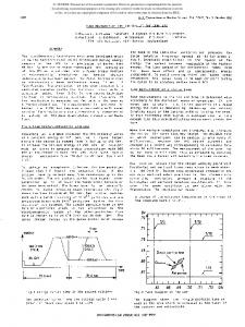
THE DIGITAL PROCESSING CHAIN The data processing architecture implemented inside the FPGA allows real time beam spectra to be continuously calculated while also allowing on-the-fly reconfiguration of all acquisition, processing and excitation parameters.
Low Pass Filtering and Decimation The selected CODEC (Cirrus Logic CS4272) supports sampling frequencies up to 198kHz, allowing digitisation to be performed at up to 16 times the LHC revolution frequency (frev). This can be used to improve the signal to noise ratio in the band of interest (frev/2) with a 32 tap filter implemented in the FPGA to filter out the signals in the uninteresting part of the spectrum. After the filtering stage the data is down-sampled to reduce the data rate in the following stages. As the oversampling factor is not fixed the decimation factor is programmable.
Calculation of FFT Spectra The FFT algorithm implemented in the FPGA is a radix-4 algorithm working with 32bit fixed point data. Particular care was taken during the coding to maximize its precision. The algorithm was tested with a signal containing two sine waves of different frequency and with 186dB of difference in their amplitudes. It was verified that both frequency lines were present with the correct amplitude in the resulting spectrum, i.e. 1 for the lowest amplitude line and 231 for the largest amplitude line. The presence of sharp transitions at the border of a data set can introduce spectral leakage, which can be minimised by using windowed data. The FPGA is therefore pre-programmed with eight available window functions, any one of which can be applied to the data.
Figure 1: Block diagram of the digital processing chain implemented in the DAB64x. 06 Instrumentation, Controls, Feedback & Operational Aspects
4204
T03 Beam Diagnostics and Instrumentation
c 1-4244-0917-9/07/$25.00 2007 IEEE
Proceedings of PAC07, Albuquerque, New Mexico, USA
FRPMN073
The coefficients required to produce the selected window are calculated and applied on-the-fly inside the FPGA while acquiring. The length of the acquisition can be set to any power of 2 up to 218. If the selected value is not a power of 4, as required for the radix-4 FFT algorithm, the data is automatically zero padded after the application of the window function. The FPGA must calculate the spectra of the signals acquired in a given data frame for both the horizontal and the vertical plane. In order to do that in a single FFT the two real signals are combined into a single complex signal. The symmetry properties of FFTs for real signals allows the horizontal and vertical spectra to be extracted from the resulting FFT with simple sum and subtraction operations performed directly in the FPGA. The resulting spectral data is stored in the same data buffer used as input for the FFT. By using two such buffers continuous acquisition can be performed, with a 50% maximum overlap between the acquisition frames. Table 1: Acquisition Length vs. FFT Bin Resolution Acquisition length
Frequency resolution
Measurement rate
1024
1*10-3
21.9 Hz -3
4096
0.24*10
5.5 Hz
16k
61*10-6
1.4 Hz
64k
-6
256k
15*10
-6
3.8*10
0.34 Hz 0.09 Hz
Trigger Generation The acquisition and excitation triggers are internally generated on the basis of either the machine millisecond clock or the turn clock. In both cases the trigger is realigned to the current sampling clock and linked to the turn clock. This avoids jitter between the start of the acquisition and the excitation. The trigger generation can be started immediately after a software command or delayed until the arrival of a “start of cycle” hardware pulse. Several other parameters are also available to control the interrelation between the acquisition and excitation triggers.
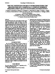
Chirp Generation and BTF Measurement The Chirp signals are generated by a digital frequency synthesizer (DFS) with 40bit phase precision which is capable of generating harmonics between DC and 13 times the LHC revolution frequency. All the parameters of the chirp, namely its length, amplitude, the start and end frequency and the frequency increment, can be configured on-the-fly according to the requirements of the particular machine cycle being measured. The reproducibility of the excitation due to the digital generation, in conjunction with its synchronism to the acquisition, allows the extraction of both the amplitude and phase of the beam transfer function. The phase 06 Instrumentation, Controls, Feedback & Operational Aspects
c 1-4244-0917-9/07/$25.00 2007 IEEE
Figure 2: Test acquisition performed in the laboratory using a tuneable resonator: 1. Spectrogram response while tuning the resonator 2. Amplitude response for the selected slice 3. Uncorrected phase response for the selected slice 4. Corrected phase response for the selected slice response of the system without beam is taken into account by directly connecting the excitation to the acquisition input, taking a reference phase measurement, and then subtracting this response from all subsequent acquisitions. Fig. 2 shows the results from such an acquisition in the laboratory, using a tuneable resonator. Once the reference phase response is taken into account, the 180° phase shift when passing over the resonance is clearly visible.
THE DEVELOPMENT SET-UP During the development of the FPGA code it was essential to be able to modify the software quickly to include and test new features. LabView, from National Instruments, in conjunction with a USB to VME bridge, from CAEN (VX1718) provided the ideal environment for this phase of the project. The selected set-up speeded up the software development phase thanks to the simple graphical design environment and allowed in-situ tests of the new FPGA code to be performed using a standard laptop during initial beam commissioning. Indeed it has T03 Beam Diagnostics and Instrumentation
4205
FRPMN073
Proceedings of PAC07, Albuquerque, New Mexico, USA
proven to be so flexible that it was decided to keep a similar system for the development installation in the LHC.
TEST RESULTS The system was initially tested in the lab to establish its noise performance using a 1024 bin FFT of a reference tone generated by the internal DFS and converted to analogue with the codec’s DAC. The measured noise floor as referred to the full scale was found to be -145dB with only the digitizer in the chain, and -130dB when the analogue front end was also included. In both cases the noise was smaller than that measured in the presence of the beam, showing that electronic noise is not a limiting factor in the measurement. These test result are shown in Fig. 3, including as a reference the FFT result of the same
LHC pilot beam. In this particular case, during the initial cycle set-up, it was possible to track the tune for the whole cycle without applying any additional external excitation. With these conditions the noise floor was at 110dB and the signal to noise ratio was 62dB. With a nominal intensity, 4200 bunch fixed target beam a small external excitation (chirp) was required to identify the tune. Fig. 5 shows the results from such a cycle, where the measured noise floor was -93dB and the signal to noise was 28dB. The use of a digitally generated synchronised chirp allowed the phase response to be obtained, leading to a full beam transfer function.
Figure 3: Noise floor measurements for various stages of the acquisition chain while exciting with a single tone.
Figure 5: Continuous beam transfer functions measurements using chirped excitation on a CERNSPS fixed target beam.
CONCLUSIONS
Figure 4: Acquisition of a single, low intensity bunch without additional external excitation. digital tone when looped back directly inside the FPGA. The system has been tested with beam during the 2006 and 2007 SPS runs as well as during RHIC Run 7, showing good results. Figure 4 shows the results from an SPS acceleration cycle with a single bunch, low intensity, 06 Instrumentation, Controls, Feedback & Operational Aspects
4206
The LHC tune measurement system been successfully tested at both the CERN-SPS and at BNL-RHIC. The combination of BBQ front-end and the implementation of a high resolution FFT algorithm in an FPGA have allowed the acquisition of continuous real-time tune spectra with a 130dB dynamic range. Additionally, the use of a digital frequency synthesiser (DFS) to produce acquisition synchronised chirp excitation has allowed for the measurement of complete beam transfer functions.
REFERENCES [1] M. Gasior and R. Jones, “High Sensitivity Tune Measurement by Direct Diode Detection”, DIPAC05, Lyon, France, 2005. T03 Beam Diagnostics and Instrumentation
c 1-4244-0917-9/07/$25.00 2007 IEEE