Dec 28, 2016 - Please refer to its issue tracker5 for open issues and features that are currently not ... 5https://bitbucket.org/jgreenyer/scenariotools/issues ...
The MechatronicUML Requirements Engineering Method: Process and Language
Technical Report tr-ri-16-351 Jörg Holtmann* , Markus Fockel* , Thorsten Koch* , David Schmelter* , Christian Brenner† , Ruslan Bernijazov* , Marcel Sander‡ *
†
Software Engineering Department, Fraunhofer IEM, Paderborn, Germany
formerly: Software Engineering Group, Heinz Nixdorf Institute, Paderborn University, Germany ‡
formerly: Software Engineering Department, Fraunhofer IEM, Paderborn, Germany
Version: 1.0 Paderborn, December 28, 2016
IEM
Contents 1 Introduction
1
2 The M ECHATRONIC UML Requirements Engineering Process 2.1 Software Requirements Engineering in the Context of Model-based Systems Engineering . . . . . . . . . . . . . . . . . . . . . . . . . . . . . . . . . . . 2.2 Requirements Modeling and Model Analysis in the Context of the M ECHA TRONIC UML Method . . . . . . . . . . . . . . . . . . . . . . . . . . . . . . 2.3 Transition to the Platform-independent Software Design with M ECHATRON IC UML . . . . . . . . . . . . . . . . . . . . . . . . . . . . . . . . . . . . .
5
10
3 M ECHATRONIC UML Requirements Language 3.1 Structure . . . . . . . . . . . . . . . . . . . . 3.1.1 Types (Classes) . . . . . . . . . . . . 3.1.2 Use Cases (Roles) . . . . . . . . . . . 3.1.3 Instances at Runtime (Objects) . . . . 3.2 Behavior: Syntax and Semantics of MSDs . . 3.2.1 Basic Elements of an MSD . . . . . . 3.2.2 Semantics of MSDs . . . . . . . . . . 3.2.3 Advanced Elements of MSDs . . . . . 3.2.4 Timed MSDs . . . . . . . . . . . . . 3.3 MSD Specifications . . . . . . . . . . . . . . 3.3.1 Environment Assumptions . . . . . . 3.3.2 Properties of MSD Specifications . .
. . . . . . . . . . . .
13 14 15 16 17 17 18 20 27 34 37 37 39
. . . . . .
41 41 45 46 49 52 61
. . . . . . . . . . . .
. . . . . . . . . . . .
. . . . . . . . . . . .
. . . . . . . . . . . .
4 Complete Example: Emergency Braking & Evading Assistance System 4.1 Introduction . . . . . . . . . . . . . . . . . . . . . . 4.2 MSD Specification . . . . . . . . . . . . . . . . . . 4.2.1 Use Case GeneralEnvironmentAssumptions . 4.2.2 Use Case ObstacleDetection . . . . . . . . . 4.2.3 Use Case EgoEmcyBrkRearCoordination . . 4.2.4 Use Case EgoEvade . . . . . . . . . . . . . .
. . . . . . . . . . . .
. . . . . .
. . . . . . . . . . . .
. . . . . .
. . . . . . . . . . . .
. . . . . .
. . . . . . . . . . . .
. . . . . .
. . . . . . . . . . . .
. . . . . .
. . . . . . . . . . . .
. . . . . .
. . . . . . . . . . . .
. . . . . .
. . . . . . . . . . . .
. . . . . .
. . . . . . . . . . . .
. . . . . .
. . . . . . . . . . . .
. . . . . .
. . . . . . . . . . . .
. . . . . .
. . . . . . . . . . . .
. . . . . .
6 9
III
IV 5 Related Work 5.1 Message Sequence Charts . . . . . . . . . . . 5.1.1 Basic Message Sequence Charts . . . 5.1.2 High-level Message Sequence Charts 5.1.3 Time . . . . . . . . . . . . . . . . . . 5.1.4 Yet Another MSC Semantics . . . . . 5.2 Live Sequence Charts . . . . . . . . . . . . . 5.3 UML Sequence Diagrams . . . . . . . . . . . 5.3.1 Interaction Overview Diagrams . . . . 5.3.2 Time . . . . . . . . . . . . . . . . . . 5.3.3 STAIRS . . . . . . . . . . . . . . . . 5.4 Property Sequence Charts . . . . . . . . . . . 5.5 Original Modal Sequence Diagrams . . . . .
CONTENTS
. . . . . . . . . . . .
. . . . . . . . . . . .
. . . . . . . . . . . .
. . . . . . . . . . . .
. . . . . . . . . . . .
. . . . . . . . . . . .
. . . . . . . . . . . .
. . . . . . . . . . . .
. . . . . . . . . . . .
. . . . . . . . . . . .
. . . . . . . . . . . .
. . . . . . . . . . . .
. . . . . . . . . . . .
. . . . . . . . . . . .
. . . . . . . . . . . .
. . . . . . . . . . . .
. . . . . . . . . . . .
69 69 69 70 70 71 71 72 73 73 73 73 75
6 Future Work
77
7 Bibliography Own Publications . . . . . . . . . . . . . . . . . . . . . . . . . . . . . . . . . . . Bachelor’s Theses, Master’s Theses, Project Group Documentations, and Ph.D. Theses Foreign Publications . . . . . . . . . . . . . . . . . . . . . . . . . . . . . . . . .
79 79 83 84
CONTENTS
V
Contributors and Acknowledgments M ECHATRONIC UML and especially its requirements engineering (RE) method is the result of many people’s work, who we are greatly indebted to. Furthermore, it was funded within the course of several research projects.
Contributors Today, Prof. Dr. Wilhelm Schäfer is the chair of M ECHATRONIC UML. The M ECHATRON IC UML RE method is jointly developed by the Software Engineering Group of the Heinz Nixdorf Institute (HNI) at the Paderborn University and the Software Engineering Department of the Fraunhofer Institute for Mechatronic Systems Design IEM (Fraunhofer IEM). Prof. Dr. Joel Greenyer, now Junior Professor at the Leibniz Universität Hannover, started the work on our scenario-based RE method while he was with the Software Engineering Group at the HNI. He designed the initial approach and developed the foundations [Gre11], and he still contributes to the project. We thank all former or current students of the Software Engineering Group of the HNI and the Software Engineering Department of the Fraunhofer IEM, who developed previous versions of the tool suite S CENARIO T OOLS MSD and contributed in the context of project groups, theses, and working student jobs. In particular, we thank the students who participated in the student project group “ScenarioTools”1 and developed the first version of the tool suite [BDF+ 10; Gre11; GF12]. In addition, we thank the RE subgroup of the student project group “SafeBots III” [BBG+ 13], who conceived and implemented hierarchical MSDs [HM13] as well as an early version of Real-time Play-out [BGH+ 14]. Furthermore, we thank the students who contributed in the context of their theses [Sch13; Shi14; Jap15]. Finally, we want to thank our former or current working students Sebastian Otutuama and Sergej Japs. The current version of S CENARIO T OOLS MSD234 is joint work of people with different affiliations. We particularly thank Grischa Liebel (Chalmers University of Technology), Dr. Valerio Panzica La Manna (Politecnico di Milano), and Prof. Dr. Matthias Tichy (Ulm University). We thank Prof. Dr. Joel Greenyer, Dr. Matthias Meyer, and David Schubert for their feedback on this technical report. Furthermore, we thank Dr. Harald Anacker for valuable discussions about the integration of the M ECHATRONIC UML RE method into the context of systems engineering (cf. Section 2.1) and Alina Linden for the creation of Figure 2.2. 1
http://www.cs.uni-paderborn.de/index.php?id=scenariotools http://www.mechatronicuml.org/en/download.html 3 http://scenariotools.org/projects2/msd/ 4 https://bitbucket.org/jgreenyer/scenariotools.git 2
VI
CONTENTS
Involved Projects The M ECHATRONIC UML RE method is and was partially developed . . . • . . . in the leading-edge cluster Intelligent Technical Systems OstWestfalenLippe (it’s OWL), which is managed by the Project Management Agency Karlsruhe (PTKA) and funded by the German Federal Ministry of Education and Research (Bundesministerium für Bildung und Forschung, BMBF), • . . . in the ITEA 2 AMALTHEA4public project, which is managed by the Project Management Agency of the German Aerospace Center (PT-DLR), • . . . in the course of the Collaborative Research Centre 614—Self-optimizing Concepts and Structures in Mechanical Engineering—of the Paderborn University, which was funded by the German Research Foundation (Deutsche Forschungsgemeinschaft, DFG), • . . . by PhD students who were funded by the International Graduate School Dynamic Intelligent Systems.
Chapter 1 Introduction Software-intensive systems (e.g., embedded [HS07], mechatronic [Aus96; VDI04], or cyberphysical systems [Poo10; SW07]) have become prevalent in our lives and, thus, people constantly interact with these systems. Whereas malfunctions in simple household appliances may have limited impact, they can lead to life-threatening accidents in cars, planes, and many medical devices, for example. Because the behavior of such safety-critical systems is controlled to a large extent by software, this software must work correctly. One crucial aspect of correct software functionality is a high quality of the requirements on the software. Errors in software-intensive systems are increasingly expensive to fix, the later they are found (e.g., [Boe81; Boe83]). Therefore, the requirements should be elicited, documented, and validated as soon as possible, which is part of the requirements engineering (RE) phase (e.g., [PR11]) within the overall development process. Modern software-intensive systems increasingly consist of multiple distributed components where single system functions are often realized by the coordination of multiple components, and where a single component may be involved in fulfilling multiple functions at the same time. This distributed and concurrent nature of the systems, combined with critical real-time aspects, introduces a substantial complexity that must be mastered during the development of these systems. Being able to precisely and comprehensibly express requirements on the message-based interaction behavior is therefore of particular importance. We call this message-based interaction behavior of the distributed components coordination behavior [PHM+ 14]. The use of models in RE for software-intensive systems is considered beneficial [STP12]. The main advantages of requirements models as documentation format are that they facilitate requirements understanding [NT09] by raising the abstraction level in requirements descriptions [CA07] and foster automatic analysis techniques. One particular form of model-based RE makes use of scenarios. A scenario describes the sequence of events required by the system under development (SUD) to accomplish a certain task [HRD10]. The M ECHATRON IC UML Requirements Engineering Method presented in this report uses a scenario notation based on Modal Sequence Diagrams (MSDs) [HM08]. This scenario notation bases on concepts of Sequence Diagrams as defined in the Unified Modeling Language (UML) [OMG15a] and Live Sequence Charts [DH01], although also other formalisms exist like timed petri nets, for example.
1
2
CHAPTER 1. INTRODUCTION
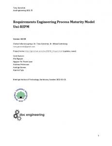
This report illustrates the application of an extended variant of the MSD notation with an advanced driver assistance system, which we introduce in detail in Chapter 4. The system dynamically coordinates several vehicles to avoid mass collisions in the presence of an obstacle on the road. For this purpose, it senses its environment, coordinates its actions with other cars, and actively performs emergency braking or evasion maneuvers. Figure 1.1 shows one scenario called EmergencyBrakingCoordination for this system. It is specified by means of a UML Sequence Diagram. The entities (e.g., a process, an object, a component, a subsystem, etc. of the environment or of the SUD) participating in one scenario are specified by means of lifelines representing these entities. In Figure 1.1, there are three lifelines front:Vehicle, ego:Vehicle, and rear:Vehicle. To specify requirements on the message-based coordination behavior between these entities, messages are specified that are exchanged between the corresponding lifelines. In Figure 1.1, front:Vehicle sends the message emcyBrakeWarning to ego:Vehicle in order to inform the latter one that the front:Vehicle will perform an emergency braking maneuver due to an obstacle on the road. Afterward, the ego:Vehicle negotiates with the rear:Vehicle whether it is safe to also perform emergency braking or whether such a maneuver would result in a potential mass collision. For this purpose, ego:Vehicle sends an emcyBrakeRequest to rear:Vehicle, and rear:Vehicle answers with an emcyBrakeResponse afterward. These messages build a partial order from the top to the bottom of the lifelines and thus a sequence of events that the particular entities of the SUD have to send and receive to fulfill the requirements. Furthermore, many approaches group the overall set of scenarios by means of use cases, which coherently represent higher level functions that can be experienced by an actor external to the SUD (i.e., an user or an external system) [BS02]. sd EmergencyBrakingCoordination
front: Vehicle
ego: Vehicle
rear: Vehicle
emcyBrakeWarning emcyBrakeRequest emcyBrakeResponse
Figure 1.1: Example scenario for an advanced driver assistance system The focus on the inter-component behavior, while abstracting from the intra-component behavior in a scenario-based notation, is well suited to specify requirements on the coordination behavior of a software-intensive system. The actual interpretation of a scenario or a specification encompassing several scenarios depends on the concrete formalism and its semantics
3 (e.g., exemplary vs. mandatory behavior). We survey several scenario-based notations and partially different semantic interpretations of them in Chapter 5. This technical report presents the model-based M ECHATRONIC UML Requirements Engineering Method, which comprises a process as well as the M ECHATRONIC UML Requirements Language. The M ECHATRONIC UML Requirements Language is a formal graphical and scenario-based language for the specification of requirements on the coordination behavior of software-intensive systems and the main focus of this technical report. The M ECHA TRONIC UML Requirements Engineering Method is part of the overall model-driven software engineering method M ECHATRONIC UML. This method comprises a process and several modeling languages for all phases of the model-driven design and development of the software for the coordination behavior of a software-intensive system. We sketch the M ECHATRON IC UML Requirements Engineering Method and the overall M ECHATRONIC UML software engineering method in Chapter 2. The M ECHATRONIC UML Requirements Language adopts the graphical notation of MSDs to express coordination behavior requirements on the SUD and extends the original MSDs as defined in [HM08] with concepts for modeling environment assumptions and real-time constraints. For this purpose, it also covers the definition of basic structural properties by using a subset of the Unified Modeling Language (UML) [OMG15a]. The formal semantics of the MSD dialect presented in Chapter 3 enable automatic analysis techniques. Particularly, these techniques encompass a simulative validation [BGP13; BGH+ 14] and a formal realizability checking approach to ensure the requirements consistency [Gre11; GBC+ 13; Jap15]. We implemented tool support for the specification and analysis of MSDs as a set of plugins for Eclipse1 as part of the S CENARIO T OOLS MSD project234 . Please refer to its issue tracker5 for open issues and features that are currently not implemented. In the next chapter, we present the M ECHATRONIC UML Requirements Engineering Process as well as its embedding into the context of an overall development process for softwareintensive systems. Chapter 3 introduces the M ECHATRONIC UML Requirements Language, and Chapter 4 presents the language applied to the advanced driver assistance system. Afterward, Chapter 5 surveys related work. Finally, we provide an outlook to future work in Chapter 6.
1
http://www.eclipse.org http://www.mechatronicuml.org/en/download.html 3 http://scenariotools.org/projects2/msd/ 4 https://bitbucket.org/jgreenyer/scenariotools.git 5 https://bitbucket.org/jgreenyer/scenariotools/issues 2
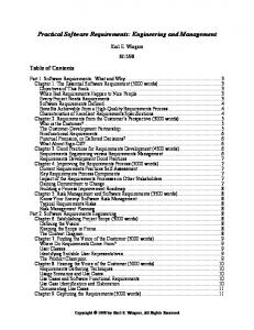
Chapter 2 The M ECHATRONIC UML Requirements Engineering Process In this chapter, we give an overview of the application of our requirements specification language within an overall development process for software-intensive systems, its modeling language aspects, and the applicable analysis techniques. The chapter is intended for readers who are interested in the process aspects of M ECHATRONIC UML and related methods. We refer readers who are mainly interested in the M ECHATRONIC UML Requirements Language directly to Chapter 3. We apply the model-driven M ECHATRONIC UML method to specify requirements on and to design the software of software-intensive systems. M ECHATRONIC UML particularly focuses on the communication behavior part of the software. M ECHATRONIC UML provides a set of domain-specific visual languages as well as a defined development process that is sketched in Figure 2.1. The method has Informal Requirements (artifact 0) as input. In Section 2.1, we sketch the application of our requirements specification language within the context of an overall development process for software-intensive systems, which can be a potential source of Informal Requirements. The M ECHATRONIC UML method starts with the specification of formal software requirements by means of MSDs in step 1, which is described in Section 2.2. Afterwards, the platform-independent software model is specified in step 2. The transition to this M ECHATRONIC UML process step is illustrated in Section 2.3. After the platformindependent design has been finished, the target platform is defined in step 3 [DP14]. This paves the way for the specification of the platform-specific software in step 4 [Bur06; Tee12; Gei15], which outputs the resulting Software Artifacts (artifact 5).
0
1
Informal Requirements
Specify Formal Software Requirements
2
Design PlatformIndependent Software Model
3 Design SW/HW Platform
4 Design PlatformSpecific Software
5 Software Artifacts (Code, Binary)
Figure 2.1: Overview of the M ECHATRONIC UML method
5
6
CHAPTER 2. THE MECHATRONICUML REQUIREMENTS ENGINEERING PROCESS
2.1 Software Requirements Engineering in the Context of Model-based Systems Engineering Software-intensive systems are characterized by the involvement of several engineering disciplines. For instance, the software engineer designs the behavior for the coordination between the SUD and its environment as well as between several subsystems within the SUD, the control engineer designs differential-equation-based controllers for the subsystems, the electrical engineer cares about sensors and actuators, and the mechanical engineer geometrically embeds the physical parts into the actual SUD. Each of these engineering disciplines applies its dedicated design methods and languages. This implicates the need for a holistic and interdisciplinary consideration of the overall system to obtain a common understanding of the SUD for all persons involved in the design. “Systems Engineering is an interdisciplinary approach and means to enable the realization of successful systems” [WRF+ 15] that aims at achieving this common understanding particularly in the early design phase. According to the INCOSE Systems Engineering Vision 2025 [INC14], the current transition from document-based Systems Engineering to Model-Based Systems Engineering (MBSE) will make Systems Engineering the future development paradigm and aspires to overcome the disadvantages of the traditional “throw-it-over-the-wall” development process [SW07]. After the development goals have become clear for all involved engineering disciplines by means of MBSE, the discipline-specific requirements engineering and design can be approached. The embedded software of a software-intensive system is jointly developed by the disciplines software engineering and control engineering. A growing part of the software for software-intensive systems is dedicated to the message-based coordination of systems, for example, car-2-car communication. This coordination behavior is specified by means of discrete, state-based, and event-triggered models [HSS+ 13; DPP+ 16; GRS14; GTS14; PHM+ 14]. We consider the discipline software engineering as the one that designs this eventdiscrete software. In contrast, the discipline control engineering designs software for continuous models based on differential equations [HSS+ 13; DPP+ 16; GRS14; GTS14; PHM+ 14]. The requirements engineering for software is considered as a branch of systems engineering [NE00], and we consider software requirements engineering as requirements engineering for the event-discrete software part of the overall system, i.e., for its coordination behavior. In this section, we outline the software requirements engineering process using MSDs within the context of the general systems engineering process for software-intensive systems as proposed by the VDI2206 [VDI04]. Figure 2.2 jointly sketches these processes by means of the left, constructive side of a V-model. Several MBSE approaches can be applied alternatively within the system design to specify a system model of the SUD in a semi-formal and discipline-spanning manner. Typically, such MBSE approaches closely align a specification method with a modeling language. For this purpose, many of these approaches tailor the Systems Modeling Language (SysML) [OMG15b] w.r.t. to their specification method (e.g., OOSEM [FMS14], SYSMOD [Wei15], or the specification technique C ONSENS [GFD+ 09] that is closely aligned with M ECHATRONIC UML [GRS14]).
2.1. SOFTWARE REQUIREMENTS ENGINEERING IN THE CONTEXT OF MODEL-BASED SYSTEMS ENGINEERING 7
Within the software requirements engineering process, we use MSDs to specify and analyze particularly the communication requirements for distributed components of the event-discrete software part of the overall system (i.e., requirements on the coordination behavior). Since we apply these formal and discipline-specific models including their dedicated analysis techniques within the software requirements engineering, this phase belongs to the modeling and model analysis branch of the VDI2206 V-model. product
n
system design environment and SUD
tegr sys
esig
md
tem in
syste
assurance of properties
atio n
requirements
informal requirements
discipline-specific design
SUD
event-discrete software
modeling and model analysis
MSD specification environment/SUD level
behavior-sequence environment/SUD level
SUD
SUD
othe
active structure SUD/subsystem level 1
r me
SUD
A
chat
B C
ronic aspe
MSD specification SUD/subsystem level 1
A
B
e.g., cts ( ) mics
dyna
.. .
behavior-sequence SUD/subsystem level 1
A
B
.. .
discipline-specific design
software engi
modeling and model analysis
Figure 2.2: Formal software requirements engineering within the context of Model-based Systems Engineering (based on [VDI04]) First of all, the environment of the SUD is specified along with the SUD’s embedding into the environment in typical MBSE approaches as well as in an MSD specification. Thus, this
8
CHAPTER 2. THE MECHATRONICUML REQUIREMENTS ENGINEERING PROCESS
information could be already existing within a system model as the result of a previous system design process. In Figure 2.2, this is depicted by the environment and SUD within the system design phase, where the yellow elements represent environment elements and the blue element represents the SUD. On this topmost hierarchy level, we consider the SUD as a black box. Based on this information, it is possible to specify and analyze an initial set of requirements for the event-discrete software part of the SUD. For this purpose, we specify sequences of events required to accomplish a certain task (cf. the introduction) either directly by means of MSDs (cf. MSD specification environment/SUD level in Figure 2.2) or based on behavioral information in the system model (cf. behavior – sequence SUD/environment level in Figure 2.2). Typically, we specify MSDs on this topmost hierarchy level if the SUD encompasses autonomous agents communicating with each other (e.g., autonomous cars [HM13], autonomous railway vehicles1 [Gre11; GF12; BGP13], delta robots [AGD+ 12], or autonomous miniature robots2 [BBG+ 13]) In the next step, the SUD’s interior structure is specified by means of a system architecture, which is indicated by the active structure SUD/subsystem level 1 in Figure 2.2. On this hierarchy level, the scenarios serve to specify the requirements for the coordination behavior of the SUD’s internal system elements. Again, this can be specified directly by means of MSDs (cf. MSD specification SUD/subsystem level 1 in Figure 2.2) or based on behavioral information in the system model (cf. behavior – sequence SUD/subsystem level 1 in Figure 2.2). An example of MSDs for the SUD’s interior subsystems is the development of an electronic control unit (ECU) of a car [BGH+ 14; KHD14; HS14; HBM+ 15; HBM+ 16; Sch13; Koc13; Shi14; Ber15; Jap15]. In this case, the overall SUD is the car conceived at the original equipment manufacturer, while the ECU—typically developed by another organizational unit like a different department or a supplier—represents one particular subsystem of the car. Nevertheless, from the viewpoint of the organizational unit developing this ECU, the development process is starting again in the left upper corner of the V, where the environment of the SUD consists of other ECUs it is interacting with. The coordination behavior requirements do not have to be formalized by means of MSDs on each of these hierarchy levels but rather in development steps when it is reasonable to analyze these requirements. We consider an advanced driver assistance system as SUD in Chapter 4 of this technical report. This SUD is actually an ECU, but since it communicates with other vehicles influencing the overall behavior of a vehicle platoon we start the system consideration on vehicle level.
1 2
http://www.railcab.de/index.php?L=1 [HSD+ 15] https://www.hni.uni-paderborn.de/en/system-and-circuit-technology/ projects/abgeschlossene-projekte/mini-robot-bebot/ [HWR09; GSD+ 11; JKK+ 14]
2.2. REQUIREMENTS MODELING AND MODEL ANALYSIS IN THE CONTEXT OF THE MECHATRONICUML METHOD
9
2.2 Requirements Modeling and Model Analysis in the Context of the M ECHATRONIC UML Method In this section, we take a closer look into the process steps to be conducted for modeling and analyzing an MSD specification. Figure 2.3 provides an overview of the M ECHATRONIC UML process with the focus on step 1, which we illustrate in the following. 0
1
Informal Requirements
Specify Formal Software Requirements
2
informal requirements
Design PlatformIndependent Software Model
specify use cases
structure of current hierarchy level
1.1
classes
4 Design PlatformSpecific Software
5 Software Artifacts (Code, Binary)
simulation collaborations
1.2 respecify structure
3 Design SW/HW Platform
1.4a specify scenarios
behavior – sequences of current hierarchy level
1.3
validation
scenarios
synthesis 1.4b
check for consistency
scenarios of higher hierarchy level
legend artifact
process step
synchronisation of artifacts
parallelization of process steps
integrated analysis step
Figure 2.3: Scenario-based requirements engineering for event-discrete software The basis for the specification of formal requirements by means of MSDs are Requirements (cf. left upper part of Figure 2.3). These can be either represented by completely informal requirements or a semi-formal system model as explained in the last section. In the following, we focus on the latter case. In terms of Figure 2.2, step 1 corresponds to one hierarchy level (i.e., MSD specification environment/SUD level or MSD specification SUD/subsystem level 1) in the modeling and model analysis part for the event-discrete software. This step is repeated for each hierarchy level. It consists of five substeps, which will be explained in the following. In step 1.1, we specify the structural basis for a MSD specification by means of UML classes [OMG15a] representing software entities. The input of step 1.1 is the structure of the current hierarchy level in a system model. This structure stems from the system design phase within the overall development process (cf. environment and SUD and active structure SUD/subsystem level 1 in Figure 2.2). We have to respecify the structure since a system model encompasses much interdisciplinary information that may be not relevant to software requirements engineering. In step 1.2, partitioning the overall functionality of the SUD into MSD use cases is conducted. We specify them by means of UML collaborations [OMG15a], which structurally capture the particular interaction participants of a use case based on the classes specified in step 1.1. The informal requirements serve as input for this step.
10
CHAPTER 2. THE MECHATRONICUML REQUIREMENTS ENGINEERING PROCESS
In step 1.3, we are now able to specify the actual behavioral scenarios by means of MSDs (cf. Section 3.2) based on the structure. Scenario-based behavior that is potentially specified in the system model may serve as input for this step. Furthermore, if there are MSD scenarios from higher hierarchy levels, this information has to be considered, too. In each case, the informal requirements serve as input for this step. When there is a fully specified an MSD specification on one hierarchy level, it is possible to analyze it in a (semi-)automatic manner due to the formal nature of MSDs. This is indicated by step 1.3a and step 1.3b in Figure 2.3. By means of the Play-out algorithm [HM03], we are able to simulate selected paths of the overall state space induced by an MSD specification in order to validate the requirements in step 1.4a [BGP13; BGH+ 14]. Furthermore, it is possible to check for the consistency of the overall MSD specification by synthesizing a global controller implementing the requirements in step 1.4b [Gre11; GBC+ 13]. If it is possible to synthesize such a controller, we say the MSD specification is consistent (cf. Section 3.3.2). These analysis techniques are not part of this technical report focusing the actual specification language of MSDs, thus we refer to the corresponding literature for detailed information.
2.3 Transition to the Platform-independent Software Design with M ECHATRONIC UML After the requirements have been validated and checked for consistency, the actual design of the software takes place. This is conducted in the M ECHATRONIC UML process in the steps 2-4 (cf. Figure 2.3). The platform-independent software model (M ECHATRONIC UML PIM) [DPP+ 16] is specified in step 2. In this step, the internal behavior of the components is specified based on the formal software requirements specfified by means of MSDs. Figure 2.4 summarizes the modeling languages that are used during steps 1 and 2 and their relationships. MSDs have a structural basis encompassing UML classes as well as collaborations (cf. Section 3.1) and define behavioral requirements (cf. Section 3.2) on Real-Time Coordination Protocols, which are used within the M ECHATRONIC UML platform-independent model to specify the coordination behavior of the system components. We use Real-Time Statecharts (RTSCs) to define the behavior of the Real-Time Coordination Protocol roles and the internal component behavior. We refer to [DPP+ 16] for more information on the M ECHATRONIC UML platformindependent design. We refer the interested reader to three approaches for the transition from RE with MSDs (step 1) to the platform-independent modeling (step 2), which we explain in the following: • Bröker [Brö11] presents the first integration of the RE process based on MSDs (cf. Section 2.2) with the model-based platform-independent software design [DPP+ 16] in M ECHATRONIC UML, which is conducted in a manual way. In step 1, she specifies the UML classes as well as the MSDs. However, she neglects the specification of UML collaborations. For the transition to step 2, she transfers the UML classes to a M ECHA -
2.3. TRANSITION TO THE PLATFORM-INDEPENDENT SOFTWARE DESIGN WITH MECHATRONICUML
11
MechatronicUML Requirements Language Structure typed by
UML Classes
define messages and attributes for
UML Collaborations
represent roles in
Modal Sequence Diagrams define formal requirements for
MechatronicUML Design Language for Platform-Independent Modeling (PIM) Real-Time Coordination Protocol instantiate + refine behavior
define behavior of
Real-Time Statechart
define communication behavior of
Component
Legend
...
Modeling Language
Artifact Relationship
Figure 2.4: Overview of the modeling languages used in M ECHATRONIC UML (based on [DPP+ 16]) TRONIC UML component model. She determines Real-Time Coordination Protocols by encapsulating several similar MSDs into one Real-Time Coordination Protocol. Afterwards, she specifies an implementation of the MSD requirements for the particular Real-Time Coordination Protocol roles by means of Real-Time Statecharts.
• In the course of the student project group SafeBots III [BBG+ 13], we present an automatic approach for the reuse of Real-Time Coordination Protocols based on requirements specified by means of MSDs. For this purpose, MSDs are input to an algorithm that checks whether once specified and stored Real-Time Coordination Protocols fulfill with a certain completeness the specified requirements on the coordination behavior. • In [Bre16], Brenner presents a synthesis of distributed controllers from MSD specifications. He also shows the integration of his work in the M ECHATRONIC UML development process. First, he illustrates how M ECHATRONIC UML software components as
12
CHAPTER 2. THE MECHATRONICUML REQUIREMENTS ENGINEERING PROCESS
well as their behavior in terms of RTSCs can be derived directly from a MSD specification. However, the overall M ECHATRONIC UML process proposes a step-wise development of the component behavior starting with role RTSCs over port RTSCs to component RTSCs. Therefore, secondly, he proposes to model role and port behavior explicitely in the MSD specification by systematically extending it with additional, corresponding lifelines. The described transition techniques have not been implemented yet though.
Chapter 3 M ECHATRONIC UML Requirements Language This chapter defines the M ECHATRONIC UML Requirements Language which is used in the M ECHATRONIC UML approach to specify formal requirements. It allows engineers to define requirements on the behavior of the system under development and assumptions about its environment. It comprises a subset of UML for defining the system structure and a variant of Modal Sequence Diagrams (MSDs) for defining the behavior. An artifact defining requirements and assumptions in the M ECHATRONIC UML Requirements Language is called an MSD specification. The top level elements of an MSD specification are use cases that include MSDs that define the behavioral requirements and assumptions for specific situations. Furthermore, an MSD specification contains a model of the structure of the system and its environment. The MSDs refer to this structure. The model of the system structure defines the subsystems of the system under development, which may further be decomposed on several levels of hierarchy. In the same way, it may define subsystems of the environment. Note hat subsystems developed by third parties must be considered as part of the environment if the concrete implementation cannot be directly controlled. The MSD specification defines subsystems on a type level and uses roles and lifelines to represent instances level. Based on the system structure, engineers can define use cases as part of the MSD specification to define requirements to be fulfilled by the system under development. Each use case defines one specific functionality to be realized. It can also define several special cases for realizing this functionality, e.g., to handle errors or other critical situations. Use cases are defined each by a set of objects or classes and a set of MSDs referring to them. When use cases refer to classes, all objects of these classes must fulfill the requirements defined in them. Use cases can overlap by referring to the same objects or classes. Then, the implementation of each class must ensure that it realizes all use cases involving objects of this class. For each use case, an MSD specification defines on the one hand how the system should behave and, on the other hand how an environment is assumed to behave in which the system may be used. In both cases, we specify the behavior by means of MSDs. We distinguish between requirement MSDs and assumption MSDs. Requirement MSDs define requirements
13
14
CHAPTER 3. MECHATRONICUML REQUIREMENTS LANGUAGE
on the system, while assumption MSDs define assumptions about the environment. We explain assumption MSDs in more detail in Section 3.3.1. MSDs are particularly suited for defining communication behavior, i.e. message exchanges between subsystems and the environment. In addition, they may also define behavior that depends on internal states or performs internal state changes. In the literature, there is a distinction between universal MSDs and existential MSDs [HM08]. While an existential MSD must be fulfilled by at least one execution of the system, universal MSDs must hold for all executions. The M ECHATRONIC UML Requirements Language is used to specify requirements a system shall fulfill. Especially safety requirements should always be fulfilled and not only in some situations. This means, we only consider requirements and assumptions that must hold for all possible system executions. Therefore, we are exclusively using universal MSDs. The MSD specification may omit details that are left to be defined later in the system development. However, it should always be a valid abstraction for the final implementation of the system under development. Both structure and behavior may further be refined in subsequent development steps. On every level of refinement, the system must be free of contradicting requirements, i.e., it must be realizable. While, theoretically, a system with contradicting environment assumptions remains realizable, there can be no environment in which it may be used. Therefore, contradicting environment assumptions are useless and should be avoided. The MSD specification can further be structured by UML packages that contain any of the structural and behavioral models defined in the following sections. These packages can also be re-used by means of merge-relations. These are represented with an arrow pointing from a parent package to a child package. The parent package then semantically includes all elements that are (recursively) contained in its child packages. Figure 3.1 shows an example for a package structure of a MSD specification. Here, the package BasePackage contains elements that are used in both packages PackageA and PackageB. The package IntegratedPackage contains all of the elements defined within any package of the diagram. The remainder of this chapter is structured as follows. Section 3.1 defines, how the engineer can model the system’s structure by using a subset of UML. Section 3.2 defines the particular variant of MSDs used in the M ECHATRONIC UML Requirements Language which allows the engineer to define requirements regarding the system’s behavior and assumptions about its environment. Finally, Section 3.3 explains in more detail under which conditions and for which combinations of environment and system an MSD specification is fulfilled.
3.1 Structure Using the M ECHATRONIC UML Requirements Language, engineers can define the structure of the system and its environment on three levels: type level, use case level and instance level. All elements on a lower level must respect the structural constraints defined by the upper level(s). As mentioned before, on the type level, the M ECHATRONIC UML Requirements Language the requirements engineer can define the system structure encompassing subsystems of the system under development as well as subsystems of the environment. On use case level, the
15
3.1. STRUCTURE
BasePackage «merge»
«merge»
PackageA
PackageB
«merge»
«merge»
IntegratedPackage
Figure 3.1: Example package diagram of a MSD specification M ECHATRONIC UML Requirements Language offers means to define the structure of parts of the system for a particular use case. On instance level, the engineer can define the structure for particular situations at runtime. The M ECHATRONIC UML Requirements Language includes different UML diagrams for each of these three levels, namely class diagrams, collaboration diagrams, and object diagrams. Figure 3.2 shows an example for each of these diagram types for one MSD specification. We will explain the individual diagrams when introducing the elements defined in them. Class diagrams define the structure of the system on type level and the possible messages that each subsystem can receive. The possible messages received by a system correspond to (public) operations of the defining class. Figure 3.2a shows an example for a class diagram. Each class defines a type that can be instantiated. Collaboration diagrams define the structure on use case level. Figure 3.2b shows an example for a collaboration diagram. Collaboration diagrams do not refer to concrete subsystems, but to abstract participants in a use case, called roles. Object diagrams define the dynamic structure of the system on instance level by defining for each subsystem an object to represent it. Figure 3.2c shows an example for an object diagram. Each object diagram corresponds to one particular situation in the system at runtime. Each object has a type corresponding to one of the classes defined in a class diagram. An object may not define any structure in addition to that defined by its class. That is, the structure defined in the object diagrams must not contradict the structure defined in the class diagrams.
3.1.1 Types (Classes) Types are defined by classes within class diagrams, as specified in the UML [OMG15a]. Figure 3.2a shows an example class diagram with three classes. The possible messages received
16
CHAPTER 3. MECHATRONICUML REQUIREMENTS LANGUAGE
Class1
Class2
c1_to_c2 1 * c1 c2
+message4() +message5()
Class3 c2_to_c3 * * c2 c3 -attribute1:Integer
+message1(param:Boolean) +message3()
+message2(param:Boolean)
(a) class diagram Collaboration1
«Environment» Part1:Class1
Part2:Class2
(b) collaboration diagram Collaboration1 c1 «Environment» object1:Class1 c1
c3 c2 object2a:Class2 c2 object3a:Class3 c2_to_c3 c2 c1_to_c2 c2_to_c3 c1_to_c2
Collaboration1
c2 object2b:Class2
c3 c2 object3b:Class3 c2_to_c3 c3
(c) object diagram
Figure 3.2: Example structure of a system by an object or part are restricted by its class: only messages corresponding to (public) operations of the corresponding class are allowed. In the example, each of the classes defines one or several operations, called message1-message5. Operations and the corresponding messages can have parameters, which are also typed. In the example, message1 and message2 each have a Boolean parameter. In MSDs, attributes and references defined for a class can be evaluated and changed for concrete objects of that class. For example, for objects of class Class3, the value of the integer attribute attribute1 can be changed.
3.1.2 Use Cases (Roles) Collaborations define the structure of a particular use case. Therefore, they specify the collection of objects that cooperate with each other to achieve the particular use case. In a Collaboration, only the aspects of an object that are relevant for the use case are incorporated, all other aspects are omitted. Thus, an object may be playing a role in several Collaborations [OMG15a]. Roles are typed by classes and can only represent objects of the corresponding class. Figure 3.2b shows a collaboration diagram with one part for Class1 and another part for Class2. Parts can be controlled by the system or by the environment. A stereotype «Environ-
3.2. BEHAVIOR: SYNTAX AND SEMANTICS OF MSDS
17
ment» attached to environment parts distinguishes them from parts controlled by the system. In the example, Part1 is controlled by the environment.
Collaborations correspond to subgraphs of the object graph that defines the runtime structure of the system (cf. Fig. 3.2c). A collaboration corresponds to several of such subgraphs if its use case occurs several times in the system. For example, the collaboration shown in Figure 3.2b corresponds in Figure 3.2c to the objects object1 and object2a and the association between them. It also corresponds to object1 and object2b and their connecting association.
3.1.3 Instances at Runtime (Objects) Object diagrams define the individual objects that are involved in a particular situation in the system at runtime. However, objects are not part of the overall MSD Specification, but are created for simulation and synthesis purposes. Object diagrams define the runtime structure of a system by a graph, where nodes represent objects and edges represent associations. Figure 3.2c shows an object diagram with one object of Class1 and two objects each of classes Class2 and Class3. Each object defines whether it is controlled by the system or by the environment. The latter case is indicated by the stereotype «Environment», the former case by its absence. In the example (cf. Figure 3.2c), object1 of Class1 is an environment object as indicated by the corresponding stereotype.
3.2 Behavior: Syntax and Semantics of MSDs This section describes the modeling of behavior with the M ECHATRONIC UML Requirements Language by means of the formalism of Modal Sequence Diagrams (MSDs). Using MSDs, engineers can define requirements on the behavior of the system under development and its environment. This section describes the syntactical elements of MSDs and their respective semantics. First, Section 3.2.1 describes the basic elements of MSDs. These constructs allow engineers to define basic message exchanges between subsystems. They are also the foundation for the more advanced constructs described subsequently. This description of the basic elements mainly covers the syntax. Second, Section 3.2.2 explains in more detail the semantics of MSDs. In other words, the section describes how MSDs relate to the runtime behavior of the final system. The descriptions in this section are limited to the syntactical constructs introduced in Section 3.2.1. Third, Section 3.2.3 introduces advanced syntactical constructs of MSDs that provide engineers with means for describing behavior beyond message exchange. While MSDs focus on message-based interactions, some aspects of behavior require referring to the internal state of subsystems or to other variables. The description comprises both, syntax and semantics of these constructs.
18
CHAPTER 3. MECHATRONICUML REQUIREMENTS LANGUAGE
Finally, Section 3.2.4 introduces syntactical elements that allow the definition of time-based behavior within MSDs by referring to special clock variables that model time. The section also explains the semantics of these constructs.
3.2.1 Basic Elements of an MSD This section introduces the basic syntactical elements comprising an MSD. These elements are essential for expressing scenario-based requirements using MSDs. Every MSD contains a set of lifelines that each represent one instance of a subsystem at runtime. Thereby, each lifeline in an MSD corresponds to a role/part defined by its containing collaboration. The message exchange between subsystems is defined by creating messages and relate them to the corresponding lifelines in an MSD. The order of messages in the diagram corresponds to the order of message exchanges in the real system. Every MSD has a name, which is shown on the top left of the MSD. Figure 3.3 shows an example of the MSD with the name BasicMSDExample. The MSD contains lifelines and messages which we will explain in the next subsections. We will explain the dashed lines between the arrows in Sect. 3.2.2. The following two subsections explain in more detail how lifelines and messages can be used to define behavior in MSDs. 3.2.1.1 Lifelines A lifelines represents an object in the system and corresponds to a role of a collaboration, i.e., entities of either the system under development or its environment (cf. Figure 3.2b). They allow engineers to refer to those entities and define their behavior. Most importantly, each message must refer to one lifeline as sender and one lifeline as receiver of the message. Graphically, lifelines are represented by vertical dashed lines with a box at the top. Figure 3.3 shows an example MSD that includes three lifelines. The lifelines represent elements of the structure defined in Figure 3.2. The text in the box has the form < NAME :T YPE >, where NAME (usually lowercase) introduces the name of the lifeline and T YPE A lifeline can also be unnamed, then the text in the box has the form . In the example, the left lifeline is unnamed. 3.2.1.2 Messages Messages are elements of MSDs that represent message exchanges between objects of the system under development and its environment. Such message exchanges at runtime are called message events. An MSD defines valid sequences of message events in the real system at runtime. The correspondence of messages to the message events at runtime is established by a process called unifaction. Please refer to Section 3.2.2 for details about the unifaction of messages and message events. Currently, we only consider synchronous messages. Consequently,
19
3.2. BEHAVIOR: SYNTAX AND SEMANTICS OF MSDS
symbolic lifelines
concrete lifeline
msd BasicMsdExample
:Class1
lifeline2:Class2
object3b:Class3
message1(paramValue1)
(c/m) message2(paramValue1)
message3
(h/e)
(c/e)
(h/m)
message4
(h/e) message5
Figure 3.3: Example MSD for Illustrating the Basic Elements of MSDs
each message exchange, comprising both sending and receiving of the message, is regarded by a single message event. Graphically, a message is represented by an arrow pointing from the sender’s lifeline to the receiver’s lifeline. The arrow is labeled with the name of the message. Figure 3.3 shows an example MSD that includes five messages. Note that sender and receiver lifeline of a message may be the same, like it is the case for message5 in the example. Messages have an execution kind: they are either executed or monitored. Executed messages are required to be sent eventually when the execution of the MSD reaches them. The MSD, and therefore the specification, is violated if they are never sent. Monitored messages never need to occur, i.e. their occurrence is optional. Executed messages are represented by a solid arrow, while monitored messages are represented by a dashed arrow. In Figure 3.3, the messages message1 and message3 are monitored while the others are executed. Messages also have a temperature: they are either hot or cold. If the execution of an MSD reaches a hot message, it must be sent before any other message in the same MSD, as explained in Section 3.2.2. Cold messages, on the contrary, do not prevent other messages from being sent. Therefore, they allow the actually exchanged messages to deviate from the sequences expressed in the MSD. If such a deviation occurs, the system does not anymore need to obey
20
CHAPTER 3. MECHATRONICUML REQUIREMENTS LANGUAGE
the rest of the MSD. Hot messages are represented by a red arrow, while cold messages are represented by a blue arrow. In Figure 3.3, the messages message1 and message2 are cold while the others are hot. In addition to the graphical differences of the arrow, temperature and execution kind can be represented by a label next to the arrow in the form (< TEMPERATURE >/< EXECUTION KIND >). The < TEMPERATURE > is either h for hot or c for cold, the < EXECUTION KIND > is either m for monitored or e for executed. Therefore the possible labels are (c/m), (h/m), (c/e), and (h/e) (cf. Figure 3.3). The textual notation is required in cases where the color of the arrow cannot be shown, like in black-and-white printouts. Messages can generally have any of the four possible combinations of temperature and execution kind. The first message in an MSD, however, must always be cold and monitored. An MSD does not restrict the possible messages in a system until the first message of the MSD has occurred. Therefore, the first message cannot express a requirement by itself but can only be a condition for the requirements expressed in the remainder of the MSD. Messages reference to operations of the class associated with the receiving lifeline. The operation represented by a message must be defined by the class of the receiving lifeline. A message always has the same name as the corresponding operation. Messages that correspond to an operation with parameters are parametrized as well. The number, order, and type of a message’s parameters are the same as for the corresponding operation. Message parameters can either be concrete values (constants) of the parameter’s type, or variables of the same type. In Figure 3.3, the messages message1 and message2 each refer to the variable paramValue1 for their parameter. Variables do not need to be declared explicitly, but rather they are defined starting with the first MSD element that mentions them. Note that the type of the parameter is not shown in the visual representation, but is defined by the corresponding operations in the classes Class2 and Class3 (cf. Figure 3.2).
3.2.2 Semantics of MSDs This section describes the semantics of MSDs, which defines how a given MSD restricts the allowed sequences of message events in the system or its environment. Both requirement and assumption MSDs express these restrictions in the same way, they only differ in whether the system or the environment is responsible for fulfilling them. 3.2.2.1 Messages at Runtime: Message Events At runtime, messages are represented by message events. Each message event corresponds to one message exchange between a sending object and a receiving object. Both, sender and receiver, can either be part of the environment or part of the system. To fulfill the specification, a system must ensure that message events can only occur if the structure supports them. That means that the class of the receiving object must have an operation corresponding to the message event. The message event has the same name as the operation. For example, the
3.2. BEHAVIOR: SYNTAX AND SEMANTICS OF MSDS
21
message message2 in Figure 3.3 corresponds to the operation message2 of class Class2 in Figure 3.2a. Each message event can correspond to several messages across several MSDs, but only to one message in each MSD. If a message event corresponds to one of the next messages expected by an MSD, this message is enabled. This correspondence between a message event and a message is determined by a process called unification. We explain message unification in the following section. The messages enabled at any given time in an MSD define the cut of the MSD. The MSD enters a new cut whenever a different set of messages is enabled. The current cut can be represented visually in the MSD by a horizontal dashed line that crosses all lifelines and is positioned directly above the elements in the MSD that will be evaluated next. Figure 3.3 shows an example MSD with all five cuts that are possible for that MSD. The topmost cut is also called initial cut. It represents the situation that there is no active MSD (c.f., Section 3.2.2.3) for the shown MSD. Figure 3.4 shows a situation where two instances of the same MSD are active. In the upper instance, message3 is enabled, while in the lower instance message4 is enabled. 3.2.2.2 Message Unification Message unification determines, whether a message and a message event correspond to each other. Two types of unifiability are defined for messages and message events. A message event can be message unifiable with a message and it can be parameter unifiable. Any message that is message unifiable with a message in the MSD is subject to the restrictions expressed by the MSD. However, the cut of the MSD only progresses for message events that are also parameter unifiable. To be message unifiable with a message, a message event needs to fulfill all of the following conditions: First, the message event needs to have the same name as the corresponding message, i.e. both must refer to the same operation. Second, the sending lifeline of the message must be able to represent the sending object of the message event. That means that the type of the lifeline must be compatible to that of the sending object and the lifeline either does not represent any object yet (it is unbound), or it already represents the sending object (it is bound to that object). The object represented by a lifeline is determined by the process of binding the lifeline, which we will explain in more detail in Section 3.2.2.4. Third, also the receiving object of the message event needs to be either bound or bindable to the receiving lifeline of the message. Fourth and finally, the order and number of parameters must be the same for message event and message and the types of the parameters must be compatible. The type of a message event’s parameter is compatible to that of a message’s parameter if it is either identical to, or a subtype of, the message’s parameter. For example, in the trace in Figure 3.4, first the message event message1(true) This message event is message unifiable to is sent from object1 to object2a. message1(paramValue1) for the following reasons. First, the (unnamed) sender lifeline is still unbound and can be bound to object1 because the type of object and lifeline is iden-
22
CHAPTER 3. MECHATRONICUML REQUIREMENTS LANGUAGE
Trace: 1. object1-> object2a: message1(true) 2. object2a->object3b: message2(true) 3. object1->object2b: message1(false) 4. object2b->object3b: message2(false) 5. object3b->object2b: message3 :Class1
lifeline2:Class2
object3b:Class3
paramValue1 = true
(c/m)
message1(paramValue1) message2(paramValue1)
message3
(h/e)
(c/e) (h/m)
message4
(h/e) message5
object2a:Class2
object3a:Class3 m es sa ge
«Environment» object1:Class1 me s sa ge4
object2b:Class2
:Class1
(c/m)
3
object3b:Class3
lifeline2:Class2
object3b:Class3
message1(paramValue1) message2(paramValue1)
message3
paramValue1 = false
(h/e)
(c/e) (h/m)
message4
(h/e) message5
Figure 3.4: Example runtime state of the MSD in Figure 3.3 for the structure in Figure 3.2
3.2. BEHAVIOR: SYNTAX AND SEMANTICS OF MSDS
23
tical. Second, lifeline2, the receiver lifeline, is also unbound and typed with Class2. Therefore, it can be bound to object2a. Third, the message name is identical to the event name. Finally, the parameter type of the event is Boolean, which is the same as the parameter type of the message. The message’s parameter type is defined by the corresponding operation in the class of the receiver object, which is message1(Boolean) in Class2 in this case. To be parameter unifiable with a message, a message event needs to be message unifiable with the message. Messages without parameters that are message unifiable are always also parameter unifiable. Messages with parameters are parameter unifiable iff they are message unifiable and the values of the parameters of the message event are compatible to the parameters specified for the message. For each parameter, two cases are possible: either the MSD specifies a concrete value for the parameter, or it specifies a variable. If a message parameter specifies a concrete value, the corresponding parameter value of the message event must be identical. If the message parameter specifies no concrete value, but a variable, the variable can either be already bound to a value (i.e. it represents the value), or it can be unbound (i.e. it represents no particular value yet). If the variable is already bound when the message becomes enabled, the message event’s value must be equal to the variable’s value. Otherwise, if the variable is still unbound when the message becomes enabled, the variable is bound to the message event’s value for the parameter. For example, in the trace in Figure 3.4, the first message event message1(true) is not only message unifiable but also parameter unifiable to the message message1(paramValue1), because paramValue1 is unbound and both paramValue1 and true are Boolean. Therefore, paramValue1 is bound to true after the first message event. The second message event message2(true) in the example trace is unifiable with the message message2(paramValue1). Note, that paramValue1 is bound to true at this point, so it would not be unifiable with a message event with the parameter false. Figure 3.5 shows further examples for parameter and message unifiability of several events with message1 in the top MSD and message2 in the bottom MSD. For each of them, the figure lists whether they are message or parameter unifiable. 3.2.2.3 MSDs at Runtime: Active MSDs At runtime, there can be several instances of each MSD with different progress each. These instances are also called active MSDs. At any point in time, the lifeline bindings and the cut of an active MSD define its runtime state. Lifeline bindings will be explained in the following section. The cut of an active MSD defines the active MSD’s current position on each lifeline, i.e., it defines which message events are expected or required to occur next. Regarding the creation of active MSDs, there exist two different variants of MSD semantics, the invariant interpretation and the iterative interpretation. In the invariant interpretation, each occurrence of a message event that is unifiable with the first message of the MSD leads to the creation of a new active MSD for it. This can lead to the creation of several active MSDs for the same MSD with the same lifeline bindings.
24
CHAPTER 3. MECHATRONICUML REQUIREMENTS LANGUAGE
a) «Environment» object1:Class1
s me
) rue 1( t e s ag
object2a:Class2
object2b:Class2
b)
message1(false)
:Class1
(c/m)
lifeline2:Class2
message1(paramValue1)
Unifiability of events with message1(paramValue1): a) paramValue1=true and lifeline2 bound to object2a b) paramValue1=false and lifeline2 bound to object2b
a) object2b:Class2
paramValue2 = false
(fa ge2 ssa e m
b) c) d)
lifeline2:Class2
lse)
object3a:Class3
object3b:Class3 message2(false) message2(true) message1(false)
object3b:Class3
message1(paramValue2) message2(paramValue2)
(c/e)
Unifiability of events with message2(paramValue2): a) not unifiable (different receiver) b) message and parameter unifiable c) only message unifiable d) not unifiable (different name) ….
Figure 3.5: Example cases for unifiability of events with messages
3.2. BEHAVIOR: SYNTAX AND SEMANTICS OF MSDS
25
In the iterative interpretation, only at most one active MSD exists for each combination of MSD and lifeline bindings. Therefore, for each such combination, a message event that is unifiable with the first message of the MSD only leads to creation of a new active MSD if there is no existing active MSD for that combination (or if the only existing active MSD is terminated by the same message event). Note that for MSDs with only concrete lifelines, the invariant interpretation can still lead to several active MSDs (due to re-occurrence of the initial message), while the iterative interpretation ensures that only one instance of each MSD exists. We use the iterative interpretation because it allows for an easier analysis of MSDs (e.g., by exploring the state space of an MSD specification with a finite state automaton). The cut of an active MSD is always “before” the next element to evaluate and advances after it when the element was evaluated. The most common element on a lifeline is a message. In that case the cut can be advanced to a subsequent position on sender and receiver lifeline when a message event occurs that is parameter unifiable with the message. There can be several enabled message events at the same time. If there is no next element on the lifeline then the cut remains at the end of the lifeline. If the cut of an active MSD advances to the end of all of its lifelines, then the active MSD terminates and becomes obsolete. Like a message, a cut has an execution kind and a temperature. If any active message in a cut is executed, the cut is executed as well. Otherwise, it is monitored. Likewise, if there is any hot message in a cut, the cut is hot as well. Otherwise, it is cold. A violation occurs in an MSD, if a message event occurs that is unifiable (cf. Section 3.2.2.2) with a message that is specified but not enabled (cf. Section 3.2.2.1) in this MSD. If an active MSD is in a hot cut when a violation occurs, it is a hot violation, which violates the requirements. We also call this a safety violation, because a safety property (i.e. something bad may not happen) is violated. It is also a hot violation if an active MSD remains in a hot cut forever. In this case, we also call this a liveness violation, because a liveness property (i.e. something good must happen) is violated. If, however, a violation occurs while all active MSDs are in a cold cut, this is a cold violation. A cold violation terminates all active MSDs which contain a message that is unifiable to the event causing the violation. Figure 3.4 shows a runtime state with two active instances of the MSD in Figure 3.3. The state corresponds to the situation after the events of the trace in the top left have occurred. While the event object1 → object2a: message1(true) instantiated the left MSD instance, the second instance was created due to object1 → object2b: message1(false). The latter event did not lead to termination of the first MSD instance, because the receiver object is a different one, preventing message unifiability. Note that in this example there are two active MSDs due to two possible lifeline bindings, regardless of whether invariant interpretation or iterative interpretation is applied. In the special case that there are several identical MSDs in the same specification, they all define exactly the same behavior and their instances are processed in exactly the same way. Therefore, only one of the identical MSDs needs to be considered.
26
CHAPTER 3. MECHATRONICUML REQUIREMENTS LANGUAGE
3.2.2.4 Lifeline Bindings The object that is represented by each particular lifeline in an active MSD is determined by a lifeline binding. A lifeline which has a (lifeline) binding is called bound, otherwise it is unbound. Lifeline bindings influence whether an active message is unifiable to a message event (cf. Section 3.2.2.2). Vice versa, unbound sender and receiver lifelines of a message become bound after unification with a message event. Then, sender and receiver lifelines become bound to the sender and receiver objects of the message event. For example, after the first message message1 in the active MSDs in Figure 3.4, the unnamed lifeline for Class1 is bound to object1 and lifeline2 is bound to either object2a or object2b, depending on the receiver of message1. The binding for a lifeline in an MSD can be different for each active MSD. While there can be several candidates for a binding before it is established, there can ultimately be only one binding for each lifeline in the same active MSD. Lifelines can be static lifelines. Static lifelines are bound to one specific object for all instances of their MSD. In other words, the binding for each lifeline is determined at design time. Lifelines that are not static lifelines are called symbolic lifelines. Symbolic lifelines are bound dynamically at runtime to an object. Both kinds of lifelines can only be bound to objects with a type compatible to the type of the lifeline. In Figure 3.4, the right lifeline is statically bound to an object, while the other two lifelines are symbolic lifelines. Here, only one instance of Class1 exists, so the left lifeline can only be bound to that object. However, the bindings for lifeline2 are different for both MSD instances, as illustrated by the dashed lines between objects and lifelines. With symbolic lifelines, the sending and receiving lifelines of the initial message are bound by unification even when no active MSD exists yet. When a message event occurs that is unifiable to the initial message of the MSD, then the new active MSD and the corresponding lifeline bindings are created at the same time. Further bindings are determined either by unification or can be defined by OCL expressions that can be attached as a comment to symbolic lifelines. We call these OCL expressions binding expressions and will explain them in Sect. 3.2.3.5.
3.2.2.5 Communication Model The most common form of communication in MSDs is that subsystems exchange messages by message events. We assume a synchronous transmission of messages, where one combined event represents both sending and receiving. While this is a useful assumption that reduces complexity of the simulation, in some cases synchronous communication is unrealistic. Therefore, we plan to extend our approach to also support asynchronous messages. Events always have one sender and one receiver. We do not consider broadcast or groupcast messages. Note that communication can also occur in a less explicit way by some of the more advanced elements of MSDs presented in the following section. Variables can be shared among several
3.2. BEHAVIOR: SYNTAX AND SEMANTICS OF MSDS
27
lifelines and they can be concurrently read and written. Conditions can span several lifelines, enforcing condition synchronization. We compare our communication model with those of similar scenario-based modeling approaches in Section 5.
3.2.3 Advanced Elements of MSDs The syntax elements presented in the preceding sections are usually sufficient for specifying message-based communication. However, in some cases, other constructs can be more suited to the problem at hand. This is usually the case when the problem domain is not easy to express in the message-based paradigm. In the following, we introduce data-centered constructs that refer to attributes of objects and variables that are local to the active MSD. These constructs enable to define behavior based on the current values of attributes and variables and to modify these values. 3.2.3.1 Variables MSDs can define variables, which are typed either by classes or by primitive data types as defined, e.g., in Java. We distinguish two types of variables: diagram variables and lifeline variables. At any point in time, both types of variables can either be unbound, i.e. they have no defined value, or they can be bound to a particular value of their type. Variables may not be read if they are unbound. Diagram variables are introduced within MSDs by using them as a parameter of a message, or by referring to them within assignments (cf. Section 3.2.3.3) or conditions (cf. Section 3.2.3.2). They are only visible within the scope of an active MSD of the MSD that defines the variable. The value of a diagram variable can be different for each active MSD. Diagram variables are assigned a concrete value either by evaluation of an assignment, or by message unification. This way they become bound. Until a concrete value is assigned to a variable, the variable remains unbound. Lifeline variables allow to refer to the object bound to a particular lifeline. For each lifeline, a corresponding lifeline variable is automatically defined. Developers can refer to lifeline variables by the name of the corresponding lifeline. Lifeline variables are bound to the object in the object system that is represented by the corresponding lifeline. Therefore, they are bound iff the corresponding lifeline is bound, unbound otherwise. Lifeline variables can be used to access attributes of the corresponding object and developers may use them wherever variables may be used. Developers can use a syntax similar to Java to refer to attributes of objects that are referenced by lifeline variables. To reference an attribute < ATTRIBUTE > of an object bound to a lifeline variable < LIFELINEVARIABLE >, developers can use a string that matches the regular expression < LIFELINEVARIABLE >(.< SUPERATTRIBUTE >)*.< ATTRIBUTE >. Here, (.< SUPER ATTRIBUTE >)* identifies the object that directly contains the attribute, possibly via several levels of hierarchy. For example, in the MSD shown in Figure 3.3, one can use the expression OB JECT 3 B . ATTRIBUTE 1 to refer to the attribute ATTRIBUTE 1 of the object that is statically bound
28
CHAPTER 3. MECHATRONICUML REQUIREMENTS LANGUAGE
to the rightmost lifeline (cf. the structure defined in Figure 3.2). Alternatively, one can refer to the same attribute by using, e.g., LIFELINE 2. C 3. ATTRIBUTE 1. 3.2.3.2 Conditions Conditions allow engineers to define for an MSD that the cut of an instance of this MSD may only advance under particular circumstances. These circumstances are defined as part of the condition as a Boolean formula. msd ConditionsExample
lifeline2:Class2
object3b:Class3
message2(boolParamValue)
(c/m)
(c)
boolParamValue
(h)
lifeline2.attribute1 > 3
(h/e)
message3
Figure 3.6: Example for the use of conditions Graphically, conditions are represented by convex hexagons with parallel opposing edges, as shown in Figure 3.6. Conditions can be either hot or cold. Like for messages, the temperature of a condition is visually defined by blue color for cold and red color for hot. In Figure 3.6, the upper condition is cold, while the lower one is hot. The graphical representation of a condition includes a text within the hexagon that defines the formula which must hold for the condition to be fulfilled. The formula of a condition must be a Boolean formula. The formula may refer to any variables which are bound before the condition’s evaluation. A condition is fulfilled iff its formula evaluates to true. The cut may only advance past the condition if it is fulfilled. A condition is enabled iff the cut is (directly) before it on all covered lifelines. If a condition (regardless if hot or cold) is fulfilled when it becomes enabled, the cut advances past the condition on all covered lifelines. If a cold condition is not fulfilled when it becomes enabled,
3.2. BEHAVIOR: SYNTAX AND SEMANTICS OF MSDS
29
this is a cold violation of the active MSD, and the active MSD terminates. If a hot condition is not fulfilled when it becomes enabled, the cut remains in front of the condition until it becomes fulfilled. Depending on the formula, it might happen that the condition can never become fulfilled. If a hot condition never becomes fulfilled after being enabled and if additionally the active MSD never terminates due to a cold violation, this is a liveness violation. Like an enabled hot message, an enabled hot condition forbids any non-enabled messages from being sent that are specified in the MSD. If such a message is sent, a hot violation occurs. In Figure 3.6, the topmost condition refers to the Boolean diagram variable boolParamValue that was previously bound to the value of the parameter of message2. As it is a cold condition, the cut only progresses if message2 was sent with the parameter true and otherwise a cold violation occurs. In the former case the second condition is reached, which refers to the value of the attribute attribute1 of the object object3b. Then, because the second condition is hot, the cut must eventually progress past the condition. Otherwise, if attribute1 is never set to a value greater than 3, it is a hot violation of the MSD. Furthermore, it is also a hot violation if message3 is sent before the cut progresses past the condition. 3.2.3.3 Assignments Assignments allow engineers to assign new values to variables. Both diagram variables and lifeline variables can be modified this way. Graphically, assignments are represented by rectangular boxes with a black border, as shown in Figure 3.7. This box contains a text in the form < VARIABLE >=< VALUE EXPRES SION > . Here, < VARIABLE > can be any variable defined for the diagram or for any object bound to one of the lifelines covered by the assignment. The term < VALUE EXPRESSION > can be any OCL expression evaluating to a value of the type of < VARIABLE > (or a subtype of the variable’s type). For example, Figure 3.7 shows an MSD where the diagram variable diagramVariable1 is set to a value of 5 if message2 with the parameter false is sent from an instance of Class2 to an instance of Class3. If message2 is sent with a parameter true afterwards, the value of diagramVariable1 is assigned to the attribute attribute1 of object3b. An assignment is enabled iff the cut is before it on all covered lifelines. An enabled assignment is immediately evaluated. Then, the cut advances past the assignment on all covered lifelines. After evaluating an assignment, the variable < VARIABLE > has a value identical to the result of evaluating < VALUE EXPRESSION >. The variable < VARIABLE > is then bound to that value. For example, after assigning the value 5 to the variable diagramVariable1 in Figure 3.7, the variable is bound to that value. Consequently, diagramVariable1 evaluates to 5 in the second assignment and object3b.attribute1 is also bound to that value. 3.2.3.4 Setter Messages Setter messages are an alternative way for engineers to assign values to the attributes of objects. When they are sent, they assign a new value to an attribute of the receiving lifeline. Compared to assignments, setter messages fit more closely to the message-based paradigm of
30
CHAPTER 3. MECHATRONICUML REQUIREMENTS LANGUAGE
msd AssignmentsExample
lifeline2:Class2
object3b:Class3
message2(false)
(c/m)
diagramVariable1 = 5 message2(true)
(c/m) object3b.attribute1 = diagramVariable1
Figure 3.7: Example for the use of assignments MSDs, but they can only modify lifeline variables, not diagram variables. Setter messages refer to operations that are implicitly defined for all attributes of a class. For an attribute with the name < ATTRIBUTE >, the name of the setter operation is SET (where is < ATTRIBUTE > with the first letter capitalized). Figure 3.8 shows an example where, instead of an assignment, a setter message is used to set the value of attribute1 of object3b. Setter operations each define one parameter of the same type as the corresponding attribute. When an object receives a message corresponding to a setter operation, it sets the attribute referenced in the operation name to the value given by the parameter. For example, in Figure 3.8, after occurrence of the message message2 with the parameter false, the setter message setAttribute1 is sent to lifeline with the parameter value 5. Consequently, the attribute attribute1 of the object is set to the value 5. 3.2.3.5 Binding Expressions Binding expressions allow engineers to specify the objects that a symbolic lifeline can reference. They cannot be specified (and have no use) for concrete lifelines. Binding expressions are graphically represented by an annotation element attached to a lifeline. Figure 3.9 depicts an example of a binding expression for lifeline3. The symbol contains a text defining the binding expression. This text is an OCL expression evaluating to an object or a set of objects each having the same type as the lifeline. Binding expressions may refer to attribute values of objects bound to any lifeline of the same MSD.
3.2. BEHAVIOR: SYNTAX AND SEMANTICS OF MSDS
31
msd SetterMessagesExample
lifeline2:Class2
object3b:Class3
message2(false)
(c/m) setAttribute1(5)
(h/e)
Figure 3.8: Example for the use of a setter message instead of an assignment A binding expression attached to a particular lifeline is evaluated if the first sent or received message of that lifeline becomes enabled during simulation or at runtime. After evaluation of a binding expression, the attached lifeline of the MSD must be bound to an object1 . If a binding expression evaluates to an object o, the lifeline with that expression is bound to the object o. If a binding expression evaluates to a set of objects O, a separate active MSD is created for each object o ∈ O by copying the original active MSD (including all existing bindings) and binding the corresponding lifeline to o. Figure 3.9 shows an MSD with three symbolic lifelines in which the initial message message3 leads to binding of lifeline1 and lifeline2. However, lifeline3 is not bound due to the initial message. Instead, the binding expression lifeline3 = lifeline2.c1 defines that lifeline3 will be bound to the object referenced by the attribute c1 of the object bound to lifeline2. For an example of possible bindings, consider the object system given in Figure 3.2 c). In this example, message3 can be sent either from object3a to object2a, or from object3b to either object2a or object2b. Depending on the first event, the corresponding bindings are created for the first two lifelines, lifeline1 and lifeline2. Thus, lifeline2 can be bound to either object2a or object2b. For both objects, the attribute c1 references object1. Consequently, lifeline3 will bind to object1 in all cases. If, however, c1 could reference more than one object, then the result of the binding expression would be a set of objects. Then, for each object in the set, one copy of the MSD in Figure 3.9 would be created. In each of these copies, the lifeline lifeline3 would be bound to the corresponding object. 1
Note that lifelines only have to be bound if one of their sent or received messages becomes enabled during simulation or at runtime. If, for example, a cold violation in an active MSD always occurs before the cut reaches any message of one of the lifelines, that lifeline may remain unbound in that particular active MSD (but must be bound in others where the cold violation does not occur).
32
CHAPTER 3. MECHATRONICUML REQUIREMENTS LANGUAGE
msd BindingExpressionsExample lifeline3 = lifeline2.c1
lifeline1:Class3
lifeline2:Class2
lifeline3:Class1
message3
(c/m) message4
(h/e)
Figure 3.9: Example for the use of binding expressions
3.2.3.6 Alternative Fragments Engineers can use alternative fragments (as defined in the UML [OMG15a]) to express that the system or the environment has several alternative ways to continue an event sequence in an MSD according to the specification. Graphically, an alternative fragment is represented by a rectangular box around the affected messages with the text “alt” in the upper left corner. It contains several compartments separated by solid horizontal lines. Figure 3.10 shows an example with two compartments. The first messages of all compartments of an alternative fragment must have the same temperature and execution kind. When the cut is directly before an alternative fragment, the cut is monitored/executed if the first message of the compartments are monitored/executed. All of these messages are considered enabled. When the first message of a compartment occurs, the cut continues right after that message within the compartment. The messages within the selected compartment are then handled in the same way as messages directly occurring in the MSD, but all messages in other compartments are ignored. Note that this also means that they cannot cause any violation anymore. When the cut reaches the end of the selected compartment, the cut immediately advances past the alternative fragment. Figure 3.10 shows an example that includes an alternative fragment with two alternatives. According to the MSD, after the event message1(true) has occurred twice, the cut reaches the alternative fragment. The cut is then hot and monitored, as defined by the first messages in the two compartments. Consequently, message1 may not be sent again. However, events for message5 and message2 may both occur, as both messages are enabled. If an event message5 occurs, the cut advances after the end of the alt fragment and the event message1(true) may occur again. Otherwise, if message2(true) occurs, message1(true) may not be sent until message2(true) occurs a second time. Note that message5 may occur as well, as it is part of the other compartment and, consequently, it is ignored by the MSD.
33
3.2. BEHAVIOR: SYNTAX AND SEMANTICS OF MSDS
msd AlternativeExample
lifeline1:Class1
lifeline2:Class2
lifeline2:Class2
message1(true)
(c/m) message1(true)
(c/m) message2(true)
alt
(h/m) message2(true)
(h/m)
(h/m) message5
message1(true)
(c/m)
Figure 3.10: Example for the use of alternative fragments 3.2.3.7 Negative Fragments Engineers can use negative fragments to express that a particular set of messages always cause a hot or cold violation if they occur while an MSD is active. A negative fragment contains messages that have no execution kind, but do have a temperature (i.e. they can be hot or cold). Messages within a negative fragment are called (hot/cold) forbidden messages. The occurrence of a hot forbidden message is a hot violation, while the occurrence of a cold forbidden message is a cold violation. Note that the order of forbidden messages within the negative fragment does not matter. Negative fragments may only be specified at the end of an MSD, i.e. no other elements in the MSD may occur lower on the lifelines. When the cut reaches a negative fragment, the MSD is terminated. Graphically, a negative fragment is represented by a rectangular box around the affected messages with the text “neg” in the upper left corner (cf. Figure 3.11). Messages in a negative fragment are represented by a dashed arrow with red/blue color for a message with a hot/cold temperature. Additionally, the temperature is indicated next to the arrow with (h/c) for (hot/cold). Optionally, negative fragments can contain several compartments that are separated by horizontal line. Then, each compartment must contain exactly one message. This separation in compartments emphasizes that the order of messages within the negative fragment does not matter, but it does not influence the semantics. Figure 3.11 shows an example for the use of negative fragments. Here, the negative fragment contains the hot forbidden message message5 and the cold forbidden message
34
CHAPTER 3. MECHATRONICUML REQUIREMENTS LANGUAGE
msd NegativeExample
lifeline1:Class1
lifeline2:Class2
lifeline2:Class2
message1(true)
(c/m) message1(true)
(c/m) message2(true)
(h/m) neg
(h)
(c)
message5
message1(false)
Figure 3.11: Example for the use of negative fragments
message1(false). Consequently, an event message5 may never occur while the MSD is active, not even in the cold cut after the first message message1(true). On the contrary, an event message1(false) may always occur, even in the hot cut before the message message2(true). Then, it will terminate the MSD with a cold violation.
3.2.4 Timed MSDs For modeling the required behavior of real-time systems or assumed real-time behavior of the environment, we need ways to explicitly express time-dependent behavior. This is supported in MSDs by clock variables and two syntactical constructs that allow to evaluate or modify them. These constructs are called clock resets and clock conditions. MSDs that define clock variables are called timed MSDs. Clock variables are diagram variables that model the passing of time. They continuously increase in value, each with the same rate. Apart from that, they can only be modified by clock resets. Clock resets are a syntactical element of MSDs that reset a clock to 0. Clock variables model the time that passed since their last reset. Clock variables can only be read in clock conditions. Clock conditions are conditions (cf. Sect. 3.2.3.2) that refer to clock variables. The engineer can define any number of clock variables for each MSD. He must define a name for each clock variable that is unique for the containing diagram.
35
3.2. BEHAVIOR: SYNTAX AND SEMANTICS OF MSDS
3.2.4.1 Clock Conditions Like ordinary conditions, clock conditions allow engineers to define that the active MSD may only advance under certain conditions. In the special case of clock conditions, the condition always requires the value(s) of one or several clock variable(s) to be in a specified interval. Graphically, clock conditions are represented like ordinary conditions, but they additionally display a sketch of an hour glass in the upper right corner of their hexagon. Figure 3.12 shows an example that includes three clock conditions for the clock c1, namely c1 > 3, c1 > 5, and c1 < 5. msd ClockConditionsExample
lifeline2:Class2
object3b:Class3
message2(false)
(c/m) (h)
c1 > 3 message2(true)
(h/e) (c)
c1 > 5 message3
(h/e) (h)
c1 < 10
Figure 3.12: Example for the use of clock conditions Like other conditions, clock conditions textually define a formula that specifies the condition for progressing further in the MSD. The clock condition’s formula may refer to any clock variables of the same MSD. The semantics of clock conditions is the same as for ordinary conditions. The only difference is that the passing of time may influence clock values and can therefore change fulfillment of the clock condition’s formula. We only support clock conditions of the form < CLOCK VARIABLE > < RELATIONAL OPER ATOR > < NATURAL NUMBER > , where a clock with the name < CLOCK VARIABLE > is compared with an integer < NATURAL NUMBER > by using an operator < RELATIONAL OPERATOR > ∈ {, ≤, ≥, ==}. Note that more complex conditions can be expressed by chaining several conditions (effectively AND-ing them) or by defining additional MSDs (to support ORing of conditions).
36
CHAPTER 3. MECHATRONICUML REQUIREMENTS LANGUAGE
The MSD in Figure 3.12 defines the following requirements. After any occurrence of an event for the message message2 with the parameter false, neither message2 nor message3 may be sent until at least 3 time units have passed. We also call such a requirement a minimal delay. In this case, it is modeled by the first hot clock condition c1 > 3, which refers to the clock c1. Note that c1 is 0 immediately after the creation of the active MSD. After c1 > 3 becomes fulfilled, message2 must be sent with the parameter true. The following cold clock condition specifies that the rest of the MSD only applies if message2(true) was sent more than 5 time units after message2(false). Otherwise, c1 is less than or equal to 5 and a cold violation occurs. If c1 > 5 is true, the object bound to lifeline2 must send the message message3. Furthermore, it must send the message less than 10 time units after message2(false), as defined by the third and final clock condition. We also call such a requirement a maximal delay. Since the condition is hot, the system must ensure that it eventually becomes true to avoid a liveness violation of the MSD. This, however, is only possible if c1 < 10 is already fulfilled right after message3 occurred. Otherwise, the condition can never be fulfilled and a hot violation of the MSD cannot be avoided anymore. Hot conditions with lower bounds, on the contrary, are guaranteed to eventually become true due to the passing of time.
3.2.4.2 Clock Resets Clock resets allow engineers to reset the current value of a clock variable to 0. After a reset, the value of the clock variable will then increase with time as usual, indicating the time that passed since the last reset. This allows engineers to specify relative timing. Graphically, clock resets are represented like assignments, but they additionally display a sketch of an hour glass in the upper right corner of their box. The label of a clock reset always has the form < CLOCK VARIABLE > = 0, where < CLOCK VARIABLE > is the name of the clock variable to reset. An enabled clock reset is immediately evaluated. After evaluating a clock reset, the cut advances after the clock reset on all covered lifelines. After evaluating a clock reset, the clock variable < CLOCK VARIABLE > has the value 0. An example is shown in Figure 3.13, where the clock c1 is reset to 0. Like an assignment, a clock reset is enabled iff the cut is before it on all covered lifelines. The MSD in Figure 3.13 shows how clock resets can be used to define a timing constraint relative to a message that is not the initial message of the MSD. The MSD requires that after an event message2(false) eventually an event message2(true) must occur. However, it does not define any conditions regarding the amount of time that may pass between these two messages. After message2(true), a clock reset sets the clock c1 to a value of 0. Therefore, c1 now measures the time that passes since message2(true). The following hot condition requires that at least 2 time units must pass before the message message3 may be sent (and before message2 may be sent again).
37
3.3. MSD SPECIFICATIONS
msd ClockResetsExample
lifeline2:Class2
object3b:Class3
message2(false)
(c/m) message2(true)
(h/e) c1 = 0
(h)
c1 > 2 message3
(c/m)
Figure 3.13: Example for the use of clock resets
3.3 MSD Specifications An MSD specification defines both what is required from the system and what is assumed about its environment. As mentioned before, it consists of a specification of the structure (cf. Section 3.1) and of the behavior (cf. Section 3.2) for both, the system and the environment. The system fulfills the specification by fulfilling both the structural and behavioral constraints. However, it is only required to do so if the environment acts according to the specified assumptions. We explain the concepts of environment assumptions in more detail in Section 3.3.1. In Section 3.3.2 we explain the properties of different kinds of MSD specifications and under which conditions they are fulfilled by a system.
3.3.1 Environment Assumptions Often, the requirements on a system can only be fulfilled if assumptions about the behavior of the system’s environment are made. The environment will usually not send all possible messages in any situation. It will instead obey some kind of (sometimes implicit) protocol which restricts the possible order and timing of messages sent by the environment. Consequently, the system can expect the messages to occur only in particular situations and only needs to react on them in these situations. If environment assumptions are specified formally as part of the specification, they can be taken into account in synthesis and simulation of the specification. Using the M ECHATRONIC UML Requirements Language, engineers can formally specify environment assumptions using assumption MSDs. Without environment assumptions, the system would need to define unnecessary behavior to handle messages which can in reality not occur in the given situation for the given environ-
38
CHAPTER 3. MECHATRONICUML REQUIREMENTS LANGUAGE
ment. This is even more important when a correct reaction of the system is not possible due to contradictory requirements in these situations. Then, the system’s specification is even unrealizable without environment assumptions, i.e. there can be no implementation of the system which fulfills the specification. We will explain realizability of specifications in more detail in the next section. Despite the advantages noted above, environment assumptions should not be unnecessarily restrictive as they limit the possible environments in which the system can be used. The system is not required to fulfill its requirements if the environment violates any of the specified assumptions. Therefore, the usage of the system in any such environment must be considered unsafe. Environment assumptions can, for instance, be derived based on physical laws, logical inference, or observations. If the system under development interacts with other man-made components in its environment, engineers can derive environment assumptions from the specification of these components, provided that they are available. Assumptions are specified using assumption MSDs. Assumption MSDs support the usual syntax of MSDs (see Section 3.2). In contrast, MSDs that specify requirements for the system behavior are called requirement MSDs. The only syntactical difference of assumption MSDs to requirement MSDs is that the stereotype «EnvironmentAssumption» is annotated at the top of the MSD. Semantically, the difference is that a hot violation in an assumption MSD is a violation of the environment assumptions while a hot violation in a requirement MSD is a violation of the requirements on the system. In other words, the environment is responsible for fulfilling the assumption MSDs, while the system is responsible for fulfilling the requirement MSDs. Figure 3.14 shows the MSD DoNotResendMessage1BeforeMessage4 as an example for an assumption MSD. It specifies an assumption about the behavior of the environment that is necessary for the system to fulfill the MSD BasicMsdExample in Figure 3.3. Without the assumption MSD, the environment can violate BasicMsdExample by first sending message1, then waiting for the system to send message2 (with the same parameter), and then sending message1 a second time. Since the MSD is in a hot cut after message2, this causes a hot violation of the MSD, i.e. the requirements are not fulfilled. Note that message2 is executed, meaning that the system has to send it eventually after message1, which inevitably leads to the above situation in which the environment can violate the requirements. The assumption MSD DoNotResendMessage1BeforeMessage4 prevents the harmful environment behavior described above. It defines that the environment will only send message1 a second time after message4 has been sent by the system. In more detail, the situation which may not occur is modeled by a hot condition false. If the cut ever reaches this condition, the assumption MSD is violated, since the condition false can never evaluate to true. The condition is only reached if message1 occurs twice without message4 occurring in between. If it does occur in between, a cold violation occurs, leading to termination of the MSD. As a result, the environment can only fulfill the assumption MSD if it waits for the system to send message4 before sending message1 again. Therefore, the requirement MSD
39
3.3. MSD SPECIFICATIONS
msd «EnvironmentAssumption» DoNotResendMessage1BeforeMessage4
:Class1
lifeline2:Class2
message1(paramValue1)
(c/m) message1(paramValue2)
(c/m)
(h)
(c/m)
false
message4
Figure 3.14: Example for an assumption MSD BasicMsdExample can be fulfilled by the system in any environment that fulfills the assumption MSD DoNotResendMessage1BeforeMessage4.
3.3.2 Properties of MSD Specifications As described above, an MSD specification consists of an early definition of the system’s structure and a set of use cases that define the required behavior of the system and the assumed behavior of its environment. The full required behavior of the system is defined by the set of all requirement MSDs that are included in any of these use cases. Likewise, the full assumed behavior of the environment is defined by the set of all assumption MSDs that are included in the use cases. To fulfill an MSD specification, the system must fulfill the structural constraints as defined by the specification. Furthermore, it must fulfill the behavioral requirements expressed in the MSDs. In the following we briefly review some important properties of specifications regarding which combinations of system and environment fulfill the specification. They are mostly derived based on the description in [Gre11]. A specification is satisfiable if there can exist a system that fulfills the specification for a cooperative environment. A cooperative environment always chooses to send messages in a way to help the system fulfill its requirements or, alternatively, attempts to violate the environment assumptions. For realistic systems, a cooperative environment is usually a too optimistic assumption.
40
CHAPTER 3. MECHATRONICUML REQUIREMENTS LANGUAGE
A satisfiable MSD specification is consistent if there can exist a system that fulfills the specification for all possible environments that fulfill all specified assumptions. A consistent specification is also called a realizable specification. A system fulfills the specification iff it fulfills all requirement MSDs for all environments that fulfill all assumption MSDs. In other words, in a given environment that violates at least one assumption MSD, any system fulfills the specification, regardless of its behavior. In an environment that fulfills all assumption MSDs, a system only fulfills the MSD specification if the system fulfills all requirement MSDs. Where not restricted by the assumption MSDs, the environment is assumed to behave arbitrarily. This means that the worst case, i.e. hostile behavior of the environment, must be expected. A consistent specification is consistently executable if the specification is fulfilled by any system that chooses its actions arbitrarily from the allowed ones. The system always sends any message sendable by system objects that is currently enabled in an active MSD as long as there are enabled messages left. This means that the specification may not define any sequence of enabled messages that leads into a situation in which the system can never leave a hot cut by sending enabled messages that are allowed by the specification. In other words, the specification ensures that the system will always fulfill its liveness requirements without violating its safety requirements, regardless of order and timing of the messages it sends.
Chapter 4 Complete Example: Emergency Braking & Evading Assistance System In this chapter, we apply the M ECHATRONIC UML requirements engineering method on a complete and self-contained example. The example is based on the so-called Emergency Braking & Evading Assistance System (EBEAS), which is an advanced automotive driver assistance system. We conceived the idea for EBEAS specifically for this technical report based on current and upcoming real-world driver assistance systems. EBEAS is supposed to reduce the risk of rear-end collisions in case of appearing obstacles in front of the vehicle. The general situation of the example is as follows: The vehicles are driving in a platoon with a constant velocity on a two-lane motorway. Each vehicle is equipped with radar sensors to detect obstacles in front, a car-to-car communication system, and a pre-crash system. In case of an unavoidable accident, the pre-crash system tightens the seat belt, moves the seat in an upright position, and closes the windows of the vehicle. If an obstacle is detected in front of the vehicle, the EBEAS takes over control and communicates with the rear-end cars to negotiate a reaction to this situation. Thereby, the EBEAS is supposed to support the driver in dangerous situations and to prevent damage from the driver and other passengers. The remainder of this chapter is structured as follows: In Section 4.1, we present the functionality of the EBEAS in further detail. In Section 4.2, we present the MSD specification of the assistance system.
4.1 Introduction The EBEAS is an advanced driver assistance system encompassing three basic functions. The radar sensors of the system are supposed to detect obstacles in front of the vehicle. The car-tocar communication system is used to communicate with other vehicles and to negotiate on the reaction to a dangerous situation. Furthermore, the pre-crash system is used to prevent serious damage from the driver and other passengers in cases in which an accident is not avoidable. Figure 4.1 depicts the general situation of the example. The four vehicles (front, ego, rear, and overtaking) are driving in a platoon with a constant velocity of v = 130[ km ] on a two-lane h motorway. The scenario of the EBEAS starts with the detection of an obstacle by the vehicle
41
CHAPTER 4. COMPLETE EXAMPLE: EMERGENCY BRAKING & EVADING ASSISTANCE SYSTEM
42 front.
By default, this vehicle is very close to the obstacle and thus also to its last point to brake. Hence it does not coordinate its reaction, but immediately starts an emergency brake Ausgangssituation des Beispiels to avoid a collision with the obstacle. Furthermore, the vehicle front sends a warning message to the following vehicle. After receiving the message, the vehicle ego has to decide how to react to the dangerous situation. On the one hand, this decision is based on the distance to Zweispurige Autos in Richtung unterwegs) the vehicle front and Autobahn whether it (alle is possible to gleicher brake safely. On the other hand, the decision is based theCar2Car-fähige situation in theFahrzeuge back. Figure 4.2 describes ego’s system behavior by means of a on Vier decision graph as a UML Activity Diagram. In general, weVehicle have toführt distinguish two different Sensorik des Front Vehicle erkennt Hindernis, Front automatische situations based on whether Notbremsung aus ego can brake safely or not. In the following, we briefly describe the situations. overtaking
rear
ego
front
Obstacle
Figure 4.1: Storyboard of the Emergency Braking & Evading Assistance System
© Fraunhofer IPT / Heinz Nixdorf Institut Folie 1
The left part of the UML Activity Diagram describes the possible situations based on the fact that the vehicle ego is able to brake safely. In the next step of the process, the possible situations for the vehicle rear are examined. Again, the decision is based on whether rear can brake safely or not. If both vehicles ego and rear can brake safely, both perform an emergency braking (cf. action (3) Emergency Brake in Figure 4.2). If rear is not able to brake safely, it is necessary to consider the situation on the second lane. If no overtaking vehicle exists, ego can safely evade to the second lane (cf. activity (7) Evade in Figure 4.2) to free up the lane for rear and to enable it to perform an emergency braking. If a vehicle overtaking exists, ego cannot simply evade. Instead, ego performs an emergency brake and activates its pre-crash system, since it knows that a collision with rear is not avoidable (cf. action (6) Emergency Brake + PreCrash (ego) in Figure 4.2). The right part of the UML Activity Diagram describes the possible situations based on the fact that the vehicle ego is not able to brake safely. Again, it is necessary to consider the situation on the second lane. If no overtaking vehicle exists, ego can simply evade on the second lane (cf. action (7) Evade in Figure 4.2). However, if an overtaking vehicle exists, ego cannot simply evade. Instead, ego performs an emergency brake and activates its pre-crash system, since it knows that a collision with rear and front is not avoidable (cf. action (10) Emergency Brake + PreCrash (front + rear) in Figure 4.2). In the following paragraphs, we elicit software requirements on the execution time of the EBEAS in hazardous situations. Therefore, we consider typical human perception-brake re-
43
4.1. INTRODUCTION
ad DecisionDiagram
(1) Decision Making
(2) Rear Coordination
[Ego can brake]
[Rear can brake]
[No overtaking exists] [Rear cannot brake]
(3) Emergency Brake
(8) Evading Determination
[Ego cannot brake]
[Overtaking exists]
(4) Evading Determination
(9) Evading Coordination
[No overtaking exists]
[Overtaking can brake]
[Overtaking exists] (5) Evading Coordination [Overtaking cannot brake] [Overtaking can brake] [Overtaking cannot brake] (6) Emergency Brake + PreCrash (rear)
(7) Evade
(10) Emergency Brake + PreCrash (front + rear)
Figure 4.2: Activity diagram for the decisions of ego
44
CHAPTER 4. COMPLETE EXAMPLE: EMERGENCY BRAKING & EVADING ASSISTANCE SYSTEM
action times and formulas for the calculation of distances covered during the perception-brake reaction time or during an emergency brake. Second, we have a look at the technical details of a car-to-car communication standard called Dedicated Short Range Communication (DSRC) [Com04; E2203] and examine the time for generating, sending, and receiving a message. Finally, we conclude that our proposed EBEAS fulfills the elicited requirements and is, therefore, a valuable addition to current driver assistance systems. The EBEAS is only a valuable addition to current driver assistance systems, if it performs the emergency braking or evading operation at least as fast and as good as the driver. Figure 4.3 visualizes important points in time and time periods in hazardous situations. The two vehicles front and ego are driving with the constant velocity v = vf ront = vego = 130[ km ] in a platoon. h Thus, both vehicles need the same distance for the emergency braking operation. Furthermore, the minimal allowed distance between the two vehicles is equal to 0.5v[m] = 65[m]. After the vehicle front starts a braking operation and activates its lights, it takes some time until the driver of the following vehicle ego recognizes the activated brake lights and fully depresses the brake pedal. This time period is called perception-brake reaction time and, according to [Gre00; ZBM+ 07], the typical human perception-brake reaction time tr is between 0.7 and 0.75 seconds. The point in time, in which the vehicle ego has the last chance to brake safely, ] and the typical is called last point to brake. Depending on the current velocity v = 130[ km h m brake deceleration on a dry driving surface a = 9[ s2 ] [ISS08], it takes tb =
130[ km ] v h = = 4[s] m a 9[ s2 ]
to perform an emergency braking operation. If the vehicle ego missed the last point to brake, it is still able to perform an evading operation to avoid the accident. Respectively, the last point in time, where the evading operation can be terminated successfully, is called last point to evade. According to [ISS08], the length of the evasion maneuver is se = 70.42m in the given scenario. Thus, it takes te =
70.42[m] se = ≈ 2[s] v 130[ km ] s
to evade. If the vehicle ego misses also the last point to brake, it is still able to activate its pre-crash system. For the proposed EBEAS, we can conclude that the system is valuable if its execution time in a hazardous situation is at most the perception-brake reaction time of a typical driver. According to [MCR09], the message delivery time td in a typical car-to-car communication scenario is equal to 1.2ms. Using this value, the driver assistance system is able to send tr 700[ms] = < 583 td 1.2[ms] messages during its execution and remains faster than a human driver. In the next section, we provide the MSD specification of the EBEAS. Thereby, it will become clear, that the pro-
45
4.2. MSD SPECIFICATION
posed system requires significantly less than the 583 messages to coordinate. Hence, we can conclude that the EBEAS is fast enough and increases the safety of the driver and passengers. Brake lights activated
Hard braking perceived
Last point Last point Last point to brake to evade to activate Pre-Crash
ego
Crash
front
≥700ms
ego vehicle can safely emergency brake
>4000ms
ego vehicle cannot safely emergency brake
Figure 4.3: Overview of different reaction times in case of an emergency brake
© Fraunhofer IPT / Heinz Nixdorf Institut Folie 1
4.2 MSD Specification The MSD specification for the EBEAS example is defined within several hierarchical packages (cf. introduction of Chapter 3), as depicted by means of the package diagram Use Cases in Figure 4.4. In this example, each package—except for Integrated—specifies the structure and behavior for one use case of the system under development. The most basic package is GeneralEnvironmentAssumptions, which is transitively included by all other packages via merge relations. It does not contain any requirements, but only assumptions about the environment. ObstacleDetection defines the basic reaction of the system when an obstacle is reported by a sensor, that is, the vehicle shall perform an emergency brake and inform other vehicles in the near periphery. The specific countermeasures to avoid a collision with these other vehicles or reducing the risks resulting from such a collision are defined independently in the packages EgoEmcyBrkRearCoordination and EgoEvade. Finally, the whole specification is combined in the package Integrated that combines all the other packages. We provide the concrete example model as part of our S CENARIO T OOLS MSD Eclipse bundle1 . The actions explained in Section 4.1 correspond to the packages as indicated by the annotated action numbers in Figure 4.4. Note that some actions spread several packages be1
http://www.mechatronicuml.org/en/download.html.
CHAPTER 4. COMPLETE EXAMPLE: EMERGENCY BRAKING & EVADING ASSISTANCE SYSTEM
46 pkg Use Cases
General Environment Assumptions «merge» Action 1 Obstacle Detection
«merge»
«merge»
Actions 2, 3, 4, 5, 6, 7
Actions 8, 9, 7, 10 EgoEmcyBrk RearCoordination
«merge»
EgoEvade
«merge»
Integrated
Figure 4.4: Use Case Overview cause each use case only defines a fraction of the behavior shown in the activity diagram in Figure 4.2.
4.2.1 Use Case GeneralEnvironmentAssumptions The use case GeneralEnvironmentAssumptions specifies general assumptions about the environment that yield for the overall MSD specification. Thus, GeneralEnvironmentAssumptions is the topmost use case in the package hierarchy (cf. Figure 4.4) and is imported by all other use cases. Figure 4.5 depicts the storyboard of this use case. GeneralEnvironmentAssumptions covers two independent interactions of every vehicle v with the environment, represented by the object env. First, after v performed an emergency break, the vehicle stands still at a later point in time. Second, after v performed an evade maneuver, the vehicle changes the lane at a later point in time. Figure 4.6 depicts the class diagram and collaboration diagram of GeneralEnvironmentAssumptions. The class diagram specifies the class Environment representing the environment that all vehicles can physically interact with. For this purpose, the operations emcyBraking and evading are specified within Enviroment for the general environment assumptions. Furthermore, the class Vehicle is specified that encompasses the operations laneChanged
47
4.2. MSD SPECIFICATION
env
1: emcy Braking
2: standstill 1: evade
2: laneChanged
v
Figure 4.5: Storyboard of use case GeneralEnvironmentAssumptions and standstill. The collaboration diagram specifies the part env representing the environment and the generic part v representing any vehicle. cd GeneralEnvironmentAssumptions Environment
Vehicle
+ emcyBraking() + evading()
+ laneChanged() + standstill()
General EnvironmentAssumptions
«Environment» env: Environment
Figure 4.6: Class diagram «EnvironmentAssumption» msd EmcyBrakeCompletionTimeRange
(c/m)
(h) (h/e) (h)
v: Vehicle
and collaboration of use case GeneralEnvironmentAssumptions «EnvironmentAssumption» msd EvadeCompletionTimeRange
The assumption MSD EmcyBrakeCompletionTimeRange in Figure 4.7 specifies the reaction of the environment on an emergency braking of a vehicle. Whenenv: theEnvironment object bound to the v: Vehicle env: Environment v: Vehicle symbolic lifeline v:Vehicle sends the message emcyBraking to env, the MSD gets activated and its clock c is reset to 0. The acknowledging message standstill from env to v repemcyBraking evading (c/m)and has a velocity of zero. Since this resents the fact that the vehicle performed a full stop emergency braking maneuver takes at least tb = 4000ms as described c=0 c = 0 in Section 4.1, there is the minimal delay c > 3500 before standstill. The 3500ms are an assumed value used here to describe that braking always takes some time(h)due tocphysical rules. c > brkCmpltnMin > evadeCmpltnMin standstill c < brkCmpltnMax
(h/e) (h)
laneChanged c < evadeCmpltnMax
General EnvironmentAssumptions
«Environment» env: Environment
v: Vehicle
CHAPTER 4. COMPLETE EXAMPLE: EMERGENCY BRAKING & EVADING ASSISTANCE SYSTEM
48
«EnvironmentAssumption» msd EmcyBrakeCompletionTimeRange
v: Vehicle
env: Environment
emcyBraking
(c/m)
«EnvironmentAssumption msd EvadeCompletionTimeR
v: Vehicle
(c/m)
c=0
(h)
Environment
standstill
(h) (h/e)
Vehicle
Figure 4.7: Environment Assumption MSD EmcyBrakeCompletionTimeRange + laneChanged() + emcyBraking() + evading()
+ standstill()
Figure 4.8 depicts the environment assumption MSD EvadeCompletionTimeRange, which basically specifies the same interaction as EmcyBrakeCompletionTimeRange but for an evaGeneral sion maneuver. That is, the actual event of fully completing a lane change after the start of EnvironmentAssumptions the evasion process takes te = 2000ms as described in Section 4.1. This is formalized in terms of a MSD by a minimal message evading from v to env and a responding message «Environment» laneChanged. The occurrence of the event unifiable with the latter message is constrained v: Vehicle env: Environment by the minimal delay c > 1500. The 1500ms are an assumed value used here to describe that the movement to the other lane always takes some time due to physical rules.
mption» onTimeRange
«EnvironmentAssumption» msd EvadeCompletionTimeRange
env: Environment
king
00
till
v: Vehicle
(c/m)
env: Environment
evading c=0
(h) (h/e)
evading c=0
c > 3500
(h/e) cd GeneralEnvironmentAssumptions
env: E
c > 1500 laneChanged
Figure 4.8: Environment Assumption MSD EvadeCompletionTimeRange
c > 1500 laneChanged
49
4.2. MSD SPECIFICATION
4.2.2 Use Case ObstacleDetection Figure 4.9 shows the interacting vehicles of the use case ObstacleDetection. The front vehicle detects an obstacle (1) that is so near to the last point to brake that there is no time to negotiate with other vehicles about what to do. Thus, the vehicle decides to do an emergency braking and informs the following vehicle ego about it (2,3). ego then has to decide what to do based on whether it itself can brake safely or not.
env
After 2: Decision Making 1: obstacle
3: emcy Braking
4: standstill
2: emcyBrake Warning
ego
front
Figure 4.9: Storyboard of use case ObstacleDetection Figure 4.10 shows the classes and collaboration for the participants of this use case. The example driver assistance system is part of a Vehicle and it interacts with other vehicles via DSRC car-to-car communication and the Environment by detecting obstacles and by braking. In this use case specifically a front vehicle interacts with the environment and a following vehicle ego. The MSD EmcyBrakeTriggering in Figure 4.11 defines, how the front vehicle has to react when detecting an obstacle in front of it. The message obstacle, sent by env, models this detection via the front vehicle’s sensors. As a reaction, the front vehicle must notify the ego vehicle via an emcyBrakeWarning message that it intends to brake. Then, it must initiate the emergency brake, which is represented by sending the message emcyBraking to the environment. The stopping of the vehicle here is represented by a standstill message from the environment. The MSD ObstacleDetectedEmcyBrkDecision in Figure 4.12 defines the first step of the ego vehicle’s reaction on the emcyBrakeWarning message from the front vehicle. After receiving this message, the ego vehicle has to check internally whether it is currently capable of performing an emergency brake. The message isEmcyBrakePossible represents this check. Depending on the outcome of the check, the message’s (out) parameter is set to true when braking is possible, and false otherwise. As the variable emcyBrakePossible is not bound here, the implementation of the ego vehicle may pick any value for the parameter. The assumption MSD ObstacleDetectionTimeBound in Figure 4.13 models the environment assumption that the front vehicle will not detect any further obstacles before obstDetMin time units have passed since the last one. As in MSD EmcyBrakeTriggering (cf.
CHAPTER 4. COMPLETE EXAMPLE: EMERGENCY BRAKING & EVADING ASSISTANCE SYSTEM
50
cd ObstacleDetection Environment
Vehicle
+ emcyBraking()
+ emcyBrakeWarning() + isEmcyBrakePossible(Boolean) + obstacle() + standstill()
cd ObstacleDetection
ObstacleDetection
Environment
Vehicle
+ emcyBraking()
+ emcyBrakeWarning() + isEmcyBrakePossible(Boolean) «Environment» front: Vehicle + obstacle() env: Environment + standstill()
ego: Vehicle
ObstacleDetection
Figure 4.10: Class diagram and collaboration of use case ObstacleDetection msd EmcyBrakeTriggering ego: Vehicle
«Environment» env: Environment
front: Vehicle
env: Environment
front: Vehicle
ego: Vehicle
obstacle
msd EmcyBrakeTriggering c=0
env: Environment
(c/m)
front: Vehicle emcyBraking
obstacle standstill
emcyBrake Warning ego: Vehicle
emcyBrake Warning
(h/e)
emcyBraking c < end2endMax (h/e) standstill (c/m)
«EnvironmentAssumption»
Figure 4.11: MSD EmcyBrakeTriggering : Obstacle is detected ⇒ front warns ego and performs msd ObstacleDetectionTimeBound an emergency brake env: Environment
front: Vehicle
obstacle «EnvironmentAssumption» c=0 msd ObstacleDetectionTimeBound
env: Environmentc > obstDetMin front: Vehicle obstacle (c/m)
c=0 Vehicle
Environment + emcyBraking() (h)
+ emcyBrakeWarning() + isEmcyBrakePossible(Boolean) c > obstDetMin + obstacle() + standstill()
51
4.2. MSD SPECIFICATION ObstacleDetection
msd ObstacleDetectedEmcyBrkDecision ego: Vehicle
«Environment» env: Environment
front: Vehicle
front: Vehicle
ego: Vehicle
emcy BrakeWarning (c/m) msd EmcyBrakeTriggering
env: Environment
isEmcyBrakePossible (emcyBrakePossible)
(h/e)
front: Vehicle
ego: Vehicle
Figure 4.12: MSD ObstacleDetectedEmcyBrkDecision (determines outcome of action 1 in obstacle (c/m) emcyBrake Figure 4.2): ego’s emergency brake decision Warning
(h/e)
emcyBraking (h/e)
Figure 4.11), the obstacle detection is represented by the minimal message obstacle from standstill (c/m) env to front. Below this message, a clock reset and the minimal delay c > 4700 is specified. The minimal delay forbids another occurrence of an event unifiable with obstacle until the minimum time has passed. Thus, env is not allowed to send any number of obstacle messages to ego, which would cause an unnecessary and awkward enlargement of the state space. In this example the scenario takes a maximum time of tr + tb = 700 + 4000s for making a decision and braking (cf. Section 4.1). We assume that another obstacle will not occur during the scenario.
«EnvironmentAssumption» msd ObstacleDetectionTimeBound
env: Environment
front: Vehicle
obstacle (c/m) c=0
(h)
c > 4700
Figure 4.13: Environment Assumption MSD ObstacleDetectionTimeBound: Obstacles are only allowed to occur every 4700ms. msd ObstacleDetectedEmcyBrkDecision
front: Vehicle
ego: Vehicle
emcy BrakeWarning (c/m) (h/e)
isEmcyBrakePossible (emcyBrakePossible)
CHAPTER 4. COMPLETE EXAMPLE: EMERGENCY BRAKING & EVADING ASSISTANCE SYSTEM
52
4.2.3 Use Case EgoEmcyBrkRearCoordination The use case EgoEmcyBrkRearCoordination describes the following scenario: ego receives the emergency brake warning of the vehicle ahead front and wants to do an emergency braking as well. If the following vehicle rear cannot brake safely (would crash into ego), ego will try to evade instead. On the neighboring lane where ego would evade to, there could be an approaching car overtaking. If it also cannot brake safely, then ego will do the emergency braking and prepare for a rear end collision with the following vehicle rear. Figure 4.14 shows the classes and collaboration for the participants of this use case. It is an extension of the classes and collaboration of Figure 4.10. It contains the additional Vehicle instances rear and overtaking and all needed messages/operations for this use case. A vehicle can currently be overtaken by another vehicle or not (cf. association overtakingVehicle in the class diagram).
cd EgoEmcyBrkRearCoordination Environment
Vehicle
+ emcyBraking() + evading()
+ emcyBrakeRequest() + emcyBrakeResponse(Boolean) + emcyBrakeWarning() + evadeRequest() + evadeResponse(Boolean) + evadeWarning() + isEmcyBrakePossible(Boolean) + laneChanged() + preCrashRear() + standstill()
0..1
overtaking Vehicle 0..1
EgoEmcyBrkRearCoordination
overtaking: Vehicle
rear: Vehicle
«Environment» env: Environment
ego: Vehicle
front: Vehicle
Figure 4.14: Class diagram and collaboration of use case EgoEmcyBrkRearCoordination
53
4.2. MSD SPECIFICATION
Figure 4.15 sketches the scenario without an overtaking vehicle, The front vehicle informs the following vehicle ego about its emergency braking (1) and ego and the trailing vehicle rear can both brake safely. ego first determines whether it itself can come to a halt without crashing into front and afterwards asks rear the same question (2). Once ego is informed by rear that it can brake safely (3), ego decides to do so and warns rear about it (4,5).
env
5: emcyBraking
6: standstill
2: emcyBrakeRequest
1: emcyBrake Warning
3: emcyBrakeResponse(true) 4: emcyBrakeWarning rear
ego
front
legend vehicle can perform emergency brake
Figure 4.15: Storyboard (actions 2/3 in Figure 4.2): ego and rear can brake The scenario depicted in Figure 4.15 is specified by the MSDs in Figures 4.16 to 4.18. In Figure 4.16 ego receives the emergency brake warning from front and determines that it can safely brake (self-message isEmcyBrakePossible(true)). Based on this precondition, ego requests permission from rear to actually do the emergency braking. msd EgoEmcyBrkRequest
front: Vehicle
msd RearEmcyBrkDecision
ego: Vehicle
rear: Vehicle
emcyBrake Warning
(c/m)
ego: Vehicle
rear
emcyBrakeRequest (c/m) isEmcyBrake Possible(true)
(c/m)
(h/e)
emcyBrakeRequest (h/e) (h/e)
emcyBrakeRespons (emcyBrakePossible
Figure 4.16: MSD EgoEmcyBrkRequest (action 2 in Figure 4.2): ego decides whether it can perform an emergency brake msd RearCanBrkEgoBrk
msd RearCantBrkEgoEvade In Figure 4.17 rear receives the emergency brake request from ego and thus determines whether it itself can brake safely. The result is used as response to ego’s request. rear: Vehicle
ego: Vehicle
env: Environment
rear: Vehicle
emcyBrakeResponse(true)
emcyBrakeResponse(
(c/m)
(c/m) emcyBrake Warning
(h/e)
e
(c) emcyBraking (h/e)
ego.overtak
CHAPTER 4. COMPLETE EXAMPLE: EMERGENCY BRAKING & EVADING ASSISTANCE SYSTEM
54
msd RearEmcyBrkDecision
ehicle
rear: Vehicle
ego: Vehicle
rear: Vehicle
emcyBrakeRequest (c/m) isEmcyBrake Possible(true)
(c/m)
isEmcyBrakePossible (emcyBrakePossible)
(h/e)
emcyBrakeRequest (h/e) (h/e)
emcyBrakeResponse (emcyBrakePossible)
Figure 4.17: MSD RearEmcyBrkDecision (determines outcome of action 2 in Figure 4.2): rear decides whether it can perform an emergency brake msd RearCantBrkEgoEvade
go: Vehicle
rue)
env: In Environment Figure 4.18
ego receives the emergency brake permission env: from rear and thus warns rear rear: Vehicle ego: Vehicle Environment of actually doing it and brakes until standstill.
Figure 4.19 describes a timing requirement for ego. It prescribes that ego has 700ms to emcyBrakeResponse(false) decide to brake (cf. emcyBraking) after it was warned by front about its emergency brake (c/m) maneuver. As this MSD focuses on theego.overtakingVehicle->isEmpty() timing requirement expressed by the clock condition (c) c < 700 all messages are cold and monitored. The maximum of 700ms stems from the time a emcyBraking evading human driver (h/e) would take to decide tr (cf. Section 4.1). (h/e) laneChanged 4.20 sketches the scenario like in Figure 4.15 with the difference that the rear vehicle (c/m) (c/m) cannot brake safely and ego thus decides to evade. Once ego is informed by rear that it cannot brake safely (3), ego decides to do evade to the next lane (4) (because there is no overtaking vehicle in danger).
standstillFigure
vade
In Figure 4.21 ego receives the emergency brake permission denial from rear (based on the MSD in Figure 4.17). Then, via a cold condition it is checked that there is no overtaking ego.overtakingVehicle msd OvertakingVehicleEmcyBrkDecision vehicle. If that is the case, the precondition of the MSD is fulfilled and ego evades to the next lane. ego: Vehicle
e(false)
overtaking:
FigureVehicle 4.22 sketches the scenario like in ego: Figure 4.20 with overtaking: the difference that there is an Vehicle Vehicle overtaking vehicle on the next lane. Once ego is informed by rear that it cannot brake safely (1), ego asks the overtaking vehicle whether it can brake safely if ego would change to its lane evadeRequest (2). If that is the case, ego will warn overtaking (c/m) and evade (4,5).
akingVehicle->notEmpty() In Figure
4.23 ego receives the emergency brake permission denial from rear (like in FigisEmcyBrakePossible (h/e) (emcyBrakePossible) ure 4.21). Then, via a cold condition it is checked whether there is an overtaking vehicle. If evadeRequest that is the case, and ego requests an evade permission evadeResponse (h/e)the precondition of the MSD is fulfilled (emcyBrakePossible) from the overtaking vehicle. (h/e)
ngCanBrkEgoEvade
msd RearAndOvertakingCantBrkEgoBrk ego.overtakingVehicle
overtaking:
ego.overtakingVehicle
overtaking:
emcyBrake Warning
(c/m)
emcyBrakeRequest (c/m) isEmcyBrake Possible(true)
(c/m)
(h/e)
emcyBrakeRequest (h/e)
4.2. MSD SPECIFICATION
emcyBrakeRespons
55 (emcyBrakePossibl
(h/e)
msd RearCanBrkEgoBrk
msd RearCantBrkEgoEvade
rear: Vehicle
ego: Vehicle
env: Environment
rear: Vehicle
emcyBrakeResponse(true)
e
emcyBrakeResponse(
(c/m)
(c/m) emcyBrake Warning
(c)
(h/e)
ego.overtak
emcyBraking (h/e) standstill
(c/m)
msd RearCantBrkEgoRequestsEvade Figure 4.18: MSD RearCanBrkEgoBrk (action 3 in Figure 4.2): rear accepts emergency braking ⇒ ego brakes ego.overtakingVehicle
msd Over
rear: Vehicle
overtaking: Vehicle
ego: Vehicle
ego:
msd EgoEmcyBrk-LastPointToBrake emcyBrakeResponse(false) (c/m) (c)
(c/m)
ego.overtakingVehicle->notEmpty()
front: Vehicle
ego: Vehicle
env: Environment evadeRequest (h/e)
emcyBrake Warning
(c/m)
(h/e)
c=0 isEmcyBrake msd RearCantBrkAndOvertakingCanBrkEgoEvade Possible(true)
(c/m)
emcyBraking ego.overtakingVehicle (c/m) (h)
c < 700 rear: Vehicle
ego: Vehicle
overtaking: Vehicle
env: Environment
Figure 4.19: MSD EgoEmcyBrk-LastPointToBrake: ego has 700ms to decide to brake. emcyBrakeResponse(false) (c/m) (c)
ego.overtakingVehicle->notEmpty() evadeRequest
(c/m) msd EgoEmcyBrk-LastPointToEvade (c/m) (h/e) front: Vehicle
evadeResponse(true) evadeWarning
ego: Vehicle
env: Environment
evading laneChanged
emcyBrake Warning
(h/e) (c/m)
CHAPTER 4. COMPLETE EXAMPLE: EMERGENCY BRAKING & EVADING ASSISTANCE SYSTEM
56
env
5: laneChanged
4: evading
1: emcyBrake Warning
2: emcyBrakeRequest msd RearEmcyBrkDecision 3: emcyBrake Response(false) rear
e
ego ego: Vehicle
rear: Vehicle legend
front
rear: Vehicle
vehicle cannot perform emergency brake
vehicle can perform emergency brake
emcyBrakeRequest
isEmcyBrake Possible(true)
(c/m)(actions 2/4/7 in Figure 4.2): ego can brake but rear not and there is Figure 4.20: Storyboard no overtaking vehicle ⇒ ego evades isEmcyBrakePossible (c/m) (h/e)
(emcyBrakePossible)
mcyBrakeRequest (h/e) (h/e)
emcyBrakeResponse (emcyBrakePossible)
msd RearCantBrkEgoEvade
ehicle
env: Environment
rear: Vehicle
ego: Vehicle
env: Environment
emcyBrakeResponse(false) (c/m) (c)
ego.overtakingVehicle->isEmpty()
emcyBraking
evading
(h/e)
(h/e) laneChanged
standstill
(c/m)
(c/m)
Figure 4.21: MSD RearCantBrkEgoEvade (actions 4/7 in Figure 4.2): rear declines emergency braking and there is no overtaker ⇒ ego evades ego.overtakingVehicle msd OvertakingVehicleEmcyBrkDecision
: Vehicle
overtaking: Vehicle
ego: Vehicle
e)
overtaking: Vehicle
evadeRequest (c/m)
Vehicle->notEmpty()
(h/e)
evadeRequest (h/e) (h/e)
evadeResponse (emcyBrakePossible)
isEmcyBrakePossible (emcyBrakePossible)
msd EgoEmcyBrkRequest
front: Vehicle
msd RearEmcyBrkDecision
ego: Vehicle
4.2. MSD SPECIFICATION
ego: Vehicle
rear: Vehicle
emcyBrake Warning
(c/m)
(c/m) isEmcyBrake Possible(true)
(h/e)
(h/e)
4: evadeWarning
(h/e)
env 3: evade Response(true)
emcyBrakeResponse (emcyBrakePossible)
5: evading
2: evadeRequest
6: lane Changed
1: emcyBrake Response(false) msd RearCanBrkEgoBrk rear
legend
emcyBrakeRequest
(c/m)
emcyBrakeRequest
overtaking
rear: Vehicl
57
ego rear: Vehicle
front
ego: Vehicle
msd RearCantBrkEgoEvade
env: Environment
vehicle can perform emergency rear: Vehiclebrake
vehicle cannot perform emergency brake
ego: Veh
Figure 4.22: StoryboardemcyBrakeResponse(true) (actions 4/5/7 in Figure 4.2): ego can brake but rear not and there is emcyBrakeResponse(false) (c/m) an overtaking vehicle that can brake ⇒ ego evades (c/m) emcyBrake Warning
(h/e)
(c) emcyBraking
ego.overtakingVeh
(h/e)
standstill
(c/m)
msd RearCantBrkEgoRequestsEvade overtaking=ego.overtakingVehicle
rear: Vehicle
(c/m)
msd OvertakingVe
overtaking: Vehicle
ego: Vehicle
ego: Vehicle
emcyBrakeResponse(false) (c/m)
(c)
e
ego.overtakingVehicle->notEmpty() evadeRequest
(h/e) (h/e)
Figure 4.23: MSD RearCantBrkEgoRequestsEvade (actions 4/5 in Figure 4.2): rear declines emergency braking and there is an overtaker ⇒ ego requests evade permission msd RearCantBrkAndOvertakingCanBrkEgoEvade
ev (emc
msd R
overtaking=ego.overtakingVehicle
rear: Vehicle
ego: Vehicle
overtaking: Vehicle
env: Environment
r
emcyBrakeResponse(false) (c/m) (c) (c/m)
(c/ ego.overtakingVehicle->notEmpty() evadeRequest
(
(c/
Environment
rear: Vehicle
ego: Vehicle
env: Environment
emcyBrakeResponse(false) (c/m)
58
(c)
CHAPTER 4. COMPLETE EXAMPLE: EMERGENCY BRAKING & EVADING ASSISTANCE SYSTEM
ego.overtakingVehicle->isEmpty() evading
(h/e) (c/m)
(h/e)
MSD OvertakingVehicleEmcyBrkDecision in Figure 4.24 handles the evade permission relaneChanged (c/m) quest. ego sends the evadeRequest message to overtaking that is implicitly bound to the corresponding symbolic lifeline. Afterwards, overtaking decides whether it itself can brake safely by means of the self message isEmcyBrakePossible and answers the evade request by means of the message evadeResponse(emcyBrakePossible).
overtakingVehicle msd OvertakingVehicleEmcyBrkDecision
overtaking: Vehicle
ego: Vehicle
overtaking: Vehicle
evadeRequest (c/m)
y()
(h/e)
isEmcyBrakePossible (emcyBrakePossible)
uest (h/e) (h/e)
evadeResponse (emcyBrakePossible)
Figure 4.24: MSD OvertakingVehicleEmcyBrkDecision (determines outcome of action 5 in msd RearAndOvertakingCantBrkEgoBrk Figure 4.2): There is an overtaking car deciding whether it can brake
go.overtakingVehicle
ego.overtakingVehicle
The MSD in Figure 4.25 describes the interactions where overtaking can brake safely and thus allows ego to evade by the message evadeResponse(true). In this case ego warns overtaking:overtaking about the imminent evading to its lane and does so. overtaking: env: Environment rear: Vehicle ego: Vehicle env: Environment Vehicle Vehicle Figure 4.26 sketches the scenario like in Figure 4.22 with the difference that the overtaking vehicle cannot brake safely and ego thus decides to do an emergency braking although the rear emcyBrakeResponse(false) vehicle cannot brake safely. It is considered less hazardous to stay in the lane and prepare for (c/m) rear end collision than to risk a side crash while evading. Once ego is informed by overtakty() (c) ego.overtakingVehicle->notEmpty() ing that it cannot brake safely (3), ego warns rear that it will brake (4), prepares for rear and quest evadeRequest collision and does the emergency braking (5). (c/m) The MSD in Figure 4.27 describes the interactions after rearevadeResponse(false) ’s emergency brake permisponse(true) (c/m) sion denial (emcyBrakeResponse(false)) and overtaking’s evade permission denial arning emcyBrake (evadeResponse(false)). In(h/e) this case ego prepares for rearpreCrashRear end collision via the selfevading Warning message preCrashRear, warns (h/e) rear about the imminent emergency braking (although rear (h/e) emcyBraking (h/e) laneChanged permitted it) and (c/m) finally does the emergency braking. standstill (c/m) Figure 4.28 describes a timing requirement for ego. It prescribes that ego has 2700ms to decide to evade (cf. evading) after it was warned by front about its emergency brake maneuver. As this MSD focuses on the timing requirement expressed by the clock condition c < 2700 all messages are cold and monitored. The maximum of 2700ms stems from the time a human driver would take to decide tr and the time needed to evade te (cf. Section 4.1).
emcyBrakeResponse(false)
evadeR
(c/m)
(c/m) ego.overtakingVehicle->notEmpty()
(c)
evadeRequest (h/e)
4.2. MSD SPECIFICATION
59
(h/e)
msd RearCantBrkAndOvertakingCanBrkEgoEvade
evadeRe (emcyBrak
msd RearAn
overtaking=ego.overtakingVehicle
rear: Vehicle
overtaking: Vehicle
ego: Vehicle
env: Environment
rear: V
emcyBrakeResponse(false) (c/m) (c)
(c/m) ego.overtakingVehicle->notEmpty()
(c)
evadeRequest (c/m)
(c/m) evadeResponse(true)
(c/m)
(c/m)
evadeWarning
(h/e)
(h/e) evading
(h/e)
laneChanged
(c/m)
Figure 4.25: MSD RearCantBrkAndOvertakingCanBrkEgoEvade (actions 5/7 in Figure 4.2): rear declines emergency braking but overtaking can brake ⇒ ego evades
overtaking 5: emcy Braking 3: evade Response(false)
env
6: standstill
2: evadeRequest 1: emcyBrakeResponse(false) 4: emcyBrakeWarning rear
ego
front
legend vehicle cannot perform emergency brake
precrash action for rear side
Figure 4.26: Storyboard (actions 4/5/6 in Figure 4.2): ego can brake but neither rear nor the existing overtaking vehicle ⇒ ego prepares for rear end collision and brakes
(h/e)
msd OvertakingVehicleEmcyBrkDecision
overtaking: Vehicle
60ego: Vehicle
(c/m)
evadeRequest
(h/e)
(h/e)
CHAPTER 4. COMPLETE EXAMPLE: EMERGENCY BRAKING & EVADING ASSISTANCE SYSTEM
isEmcyBrakePossible (emcyBrakePossible)
evadeResponse (emcyBrakePossible)
msd RearAndOvertakingCantBrkEgoBrk overtaking=ego.overtakingVehicle
vironment
rear: Vehicle
ego: Vehicle
overtaking: Vehicle
env: Environment
emcyBrakeResponse(false) (c/m) (c)
ego.overtakingVehicle->notEmpty() evadeRequest
(c/m)
evadeResponse(false)
(c/m) (h/e) (h/e) (c/m)
(h/e)
emcyBrake Warning
preCrashRear emcyBraking standstill
(h/e) (c/m)
Figure 4.27: MSD RearAndOvertakingCantBrkEgoBrk (actions 5/6 in Figure 4.2): rear and overtaking decline emergency braking (they cannot brake) ⇒ ego brakes
e )
(h)
c < 700
61
4.2. MSD SPECIFICATION
msd EgoEmcyBrk-LastPointToEvade
front: Vehicle
(c/m)
ego: Vehicle
env: Environment
emcyBrake Warning c=0 isEmcyBrake Possible(false)
(c/m)
evading (c/m) c < 2700
(h)
Figure 4.28: MSD EgoEmcyBrk-LastPointToEvade: ego has 2700ms to decide to evade.
4.2.4 Use Case EgoEvade
The use case EgoEvade describes the scenario that ego cannot perform an emergency brake in the available time frame without crashing into front. Thus, ego’s most suitable alternative is to evade on the second lane to avoid this crash. But, if there is an overtaking car on the second lane, this evasion maneuver could result in an even more hazardous crash. Therefore, ego has to determine whether there is an overtaking car on the second lane. If so, they have to handle out whether overtaking can perform an emergency break without crashing into ego. If overtaking cannot brake, ego has only the choice between a crash with overtaking or front. The ertaking=ego.overtakingVehicle latter crash will be chosen, since this is probably the less hazardous one because no evasion maneuver is performed at the same time. In this worst case scenario, additional pre crash actions are performed for both the front and rear side of ego. overtaking: env: Environment Figure 4.29 shows the class and collaboration diagram of this use case. They contain the Vehicle same classes and parts as the ones in Figure 4.14 from use case EgoEmcyBrkRearCoordination (cf. Section 4.2.3). However, the class Vehicle lacks the operation emcyBrakeRequest and emcyBrakeResponse, and additionally contains the operation preCrashFront. Empty() Figure 4.30 depicts the storyboard for the first part of the scenario. Here, ego receives the message emcyBrakeWarning and determines that it cannot brake safely within the needed deRequest time frame. Furthermore, it detects no overtaking car. Thus, it can safely perform an evasion Response(false) maneuver. Figure 4.31 shows the corresponding MSD NoOvertakingVehicle for this situation. After CrashRear the occurrence of an event unifiable with the message emcyBrakeWarning, ego deteremcyBraking mines whether(h/e) there is no overtaking car. This is specified by means of the cold condition standstill ego.overtakingVehicle→isEmpty(). By evaluating this condition, it is checked (c/m)
CHAPTER 4. COMPLETE EXAMPLE: EMERGENCY BRAKING & EVADING ASSISTANCE SYSTEM
62 cd EgoEvade
Environment
Vehicle
+ emcyBraking() + evading()
+ emcyBrakeWarning() + evadeRequest() + evadeResponse(Boolean) + evadeWarning() + isEmcyBrakePossible(Boolean) + laneChanged() + preCrashFront() + preCrashRear() + standstill()
0..1
overtaking Vehicle 0..1
EgoEvade
overtaking: Vehicle
rear: Vehicle
«Environment» env: Environment
ego: Vehicle
front: Vehicle
Figure 4.29: Class diagram and collaboration of use case EgoEvade msd NoOvertakingVehicle whether there is an overtakingVehicle link between ego and another :Vehicle. If the cold condition evaluates to false, the MSD progresses and ego has to determine whether it can brake safely. The raise of the corresponding event for this decision is specified by means of the exfront: Vehicle ego: Vehicle env: Environment ecuted message isEmcyBrakePossible(emcyBrakePossible) in the MSD ObstacleDetectedEmcyBrkDecision (cf. Figure 4.12) of the use case ObstacleDetection (cf. Section 4.2.2). The MSD NoOvertakingVehicle only progresses if ego cannot brake safely, i.e., if emcyBrakeWarning (c/m) the parameter of isEmcyBrakePossible evaluates to false. In this case, ego sends a message evading to env.(c/m) The evasion maneuver is completed when env confirms this with isEmcyBrake Possible(false) the message laneChanged. MSD OvertakingVehicleEmcyBrkDecision in Figure 4.32 handles the case that there is an ego.overtakingVehicle->isEmpty() overtaking vehicle. In this (c) case, ego sends an evadeRequest message to overtaking that is implicitly bound to the corresponding symbolic lifeline. Afterwards, overtaking decides evading internally by means of the self message isEmcyBrakePossible and(h/e) answers by means laneChanged of the message evadeResponse(emcyBrakePossible). (c/m) Note that the MSD OvertakingVehicleEmcyBrkDecision in Figure 4.32 is identical to the MSD with the same name of the use case EgoEmcyBrkRearCoordination (cf. Section 4.2.3) in Figure 4.24. Identical MSDs in the same specification do not change the semantics of the msd OvertakingVehicleEmcyBrkPossible ego.overtakingVehicle
msd Ove
front: Vehicle
ego: Vehicle
overtaking: Vehicle
env: Environment
ego
emcyBrakeWarning (c/m) (c/m)
cd EgoEvade
63
4.2. MSD SPECIFICATION Environment
Vehicle
+ emcyBraking() + evading()
0..1
+ emcyBrakeWarning() + evadeRequest() + evadeResponse(Boolean) + evadeWarning() + isEmcyBrakePossible(Boolean) + laneChanged() + preCrashFront() + preCrashRear() + standstill()
env
overtaking Vehicle 0..1
3: laneChanged
2: evading
1: emcy EgoEvade BrakeWarning ego overtaking:
«Environment» front env: Environment
Vehicle
legend vehicle cannot perform emergency brake rear: Vehicle
ego: Vehicle
front: Vehicle
Figure 4.30: Storyboard (actions 8/7 in Figure 4.2): No overtaking car ⇒ ego should overtake
msd NoOvertakingVehicle
front: Vehicle
ego: Vehicle
env: Environment
emcyBrakeWarning (c/m) (c)
ego.overtakingVehicle->isEmpty()
isEmcyBrake Possible(false)
(c/m)
evading
(h/e)
laneChanged (c/m)
Figure 4.31: MSD NoOvertakingVehicle (actions 8/7 in Figure 4.2): No overtaking car ⇒ ego should overtake msd OvertakingVehicleEmcyBrkPossible
ego.overtakingVehicle
msd O
front: Vehicle
ego: Vehicle
overtaking: Vehicle
env: Environment
e
emcyBrakeWarning (c/m) (c)
(c/m)
ego.overtakingVehicle->notEmpty() isEmcyBrake Possible(false)
(c/m
(h/e) (c/m)
CHAPTER 4. COMPLETE EXAMPLE: EMERGENCY BRAKING & EVADING ASSISTANCE SYSTEM
64
specification as both are executed in exactly the same way, i.e. they are always in identical cuts. Thus, at each point in time they allow, require or forbid the same events to occur. msd OvertakingVehicleEmcyBrkDecision
env: Environment ego: Vehicle
overtaking: Vehicle
evadeRequest (c/m) (h/e)
isEmcyBrakePossible (emcyBrakePossible)
evadeResponse (emcyBrakePossible) (h/e)
ng
anged
Figure 4.32: MSD OvertakingVehicleEmcyBrkDecision (determines outcome of action 9 in Figure 4.2): There is an overtaking car deciding whether it can brake (h/e) (c/m)
Figure 4.33 depicts the storyboard of the case that there is an overtaking vehicle that can safely brake when ego would perform an evasion maneuver. ego asks overtaking by means of an evadeRequest message that is confirmed with the message evadeResponse(true). Afterwards, ego evades after sending an evadeWarning to overtaking and performs the evasion maneuver. overtaking 4: evadeWarning rear: Vehicle
env: Environment
3: evade Response(true)
2: evadeRequest
env 5: evading
6: laneChanged 1: emcy BrakeWarning ego
front
legend vehicle cannot perform emergency brake
vehicle can perform emergency brake
Figure 4.33: Storyboard (actions 9/7 in Figure 4.2): There is an overtaking car that can brake ⇒ ego should overtake Figure 4.34 shows the corresponding MSD OvertakingVehicleEmcyBrkPossible for this situation. After the reception of an emcyBrakeWarning, there is the cold condition
(h/e) (c/m)
msd NoOvertakingVehicle
front: Vehicle
4.2. MSD SPECIFICATION (c/m)
ego: Vehicle
env: Environment
65
emcyBrakeWarning
(c) ego.overtakingVehicle->isEmpty() ego.overtakingVehicle→notEmpty(). Thus, the MSD only progresses if there is an overtakingVehicle link and hence an object can be bound to the symbolic lifeline overtaking:Vehicle by means of the OCL expression ego.overtakingVehicle. The determinaisEmcyBrake (c/m) tion that no emergency brake is possible is specifiedPossible(false) by means of the cold monitored message isEmcyBrakePossible(false) as in the MSD NoOvertakingVehicle (cf. Figure 4.31). evading (h/e) Afterward, ego sends an evadeRequest to this overtaking object. The MSD only progresses laneChanged if the parameter of evadeResponse evaluates to true. This decision is made in the MSD OvertakingVehicleEmcyBrkDecision (cf. Figure 4.32) described above.(c/m) Afterwards, ego sends an evadeWarning to overtaking. The actual evasion maneuver is performed as described in MSD NoOvertakingVehicle (cf. Figure 4.31).
msd OvertakingVehicleEmcyBrkPossible
front: Vehicle
overtaking=ego.overtakingVehicle
overtaking: Vehicle
ego: Vehicle
env: Environment
emcyBrakeWarning (c/m) (c)
ego.overtakingVehicle->notEmpty() isEmcyBrake Possible(false)
(c/m)
evadeRequest
(h/e)
evade Response(true)
(c/m)
evadeWarning
(h/e)
evading laneChanged
(h/e) (c/m)
Figure 4.34: MSD OvertakingVehicleEmcyBrkPossible (actions 9/7 in Figure 4.2): There is an overtaking car that can brake ⇒ ego should overtake msd OvertakingVehicleEmcyBrkNotPossible
Figure 4.33 depicts the storyboard of theovertaking=ego.overtakingVehicle case that there is an overtaking vehicle that can not safely brake when ego would perform an evasion maneuver. Thus, in contrast to the storyboard before, overtaking denies egos evadeRequest by means of the message evadeResponse(false). Since ego cannot overtaking: perform neither anrear: emergency norEnvironment an front: Vehicle ego: Vehicle Vehicle brakeenv: Vehicle evasion maneuver, ego has to warn rear and perform precrash operations for the front as well as the rear side in this worst case scenario. (c/m) (c)
(c/m)
(h/e)
emcyBrakeWarning ego.overtakingVehicle->notEmpty() isEmcyBrake Possible(false) evadeRequest evade
CHAPTER 4. COMPLETE EXAMPLE: EMERGENCY BRAKING & EVADING ASSISTANCE SYSTEM
66 overtaking
5: emcy Braking 3: evade Response(false)
env
6: standstill 2: evadeRequest 4: emcy BrakeWarning rear
ego
1: emcy BrakeWarning
front
legend vehicle cannot perform emergency brake
precrash actions for rear and front side
Figure 4.35: Storyboard (actions 9/10 in Figure 4.2): There is an overtaking car that cannot brake ⇒ ego has to prepare precrash actions for front and rear Figure 4.36 shows the corresponding MSD OvertakingVehicleEmcyBrkNotPossible for this situation. It starts to differ from MSD OvertakingVehicleEmcyBrkPossible (cf. Figure 4.34) beginning from the message evadeResponse(false). Thus, the MSD only progresses if overtaking cannot brake. In this case, ego sends a message emcyBrakeWarning to rear and sends the self messages preCrashFront and preCrashRear. Afterwards, the emergency brake menuever is performed as in the use case EgoEmcyBrkRearCoordination (cf. Section 4.2.3). Figure 4.37 describes a timing requirement for ego (same as Figure 4.28). It prescribes that ego has 2700ms to decide to evade (cf. evading) after it was warned by front about its emergency brake maneuver. As this MSD focuses on the timing requirement expressed by the clock condition c < 2700 all messages are cold and monitored. The maximum of 2700ms stems from the time a human driver would take to decide tr and the time needed to evade te (cf. Section 4.1).
(c)
ego.overtakingVehicle->notEmpty() isEmcyBrake Possible(false)
(c/m)
(h/e)
evadeRequest
(h/e)
evade Response(true)
4.2. MSD SPECIFICATION (c/m)
67
evadeWarning
(h/e)
evading laneChanged
msd OvertakingVehicleEmcyBrkNotPossible
front: Vehicle
(c/m) (c)
(c/m)
(h/e) (c/m) (h/e)
(h/e) (c/m)
overtaking=ego.overtakingVehicle
overtaking: Vehicle
ego: Vehicle
rear: Vehicle
env: Environment
emcyBrakeWarning ego.overtakingVehicle->notEmpty() isEmcyBrake Possible(false) evadeRequest evade Response(false) emcyBrakeWarning
(h/e)
preCrashFront
(h/e)
preCrashRear emcyBraking standstill
(h/e) (c/m)
Figure 4.36: MSD OvertakingVehicleEmcyBrkNotPossible (actions 9/10 in Figure 4.2): There is an overtaking car that cannot brake ⇒ ego has to prepare precrash actions for front and rear
(
ertaking Vehicle
CHAPTER 4. COMPLETE EXAMPLE: EMERGENCY BRAKING & EVADING ASSISTANCE SYSTEM
68
e
msd EgoEvade-LastPointToEvade
front: Vehicle
ego: Vehicle
env: Environment
vironment emcyBrake Warning
(c/m)
c=0 isEmcyBrake Possible(false)
(c/m)
evading (c/m) c < 2700
(h)
(h/e) (c/m)
Figure 4.37: MSD EgoEvade-LastPointToEvade: ego has 2700ms to decide to evade.
gVehicle msd OvertakingVehicleEmcyBrkDecision
env: Environment
ading
Changed
ego: Vehicle
overtaking: Vehicle
evadeRequest (c/m) (h/e) evadeResponse (emcyBrakePossible) (h/e)
(h/e) (c/m)
isEmcyBrakePossible (emcyBrakePossible)
Chapter 5 Related Work This chapter compares other scenario-based languages as sketched in the introduction to the MSD dialect presented in this technical report. We first describe Message Sequence Charts (MSCs), one of the earliest scenario notations. Afterwards, we investigate Live Sequence Charts (LSCs), which slightly modify the syntax and semantics of MSCs. Ideas of both scenario notations have found their way into the UML Sequence Diagrams, which are described in Section 5.3. Since the semantics of UML Sequence Diagrams contain some contradictions, an UML-compliant variant of LSCs called Modal Sequence Diagrams (MSDs) originally was introduced by Harel and Maoz [HM08]. The MSDs presented in this document are a slightly modified and extended dialect of these original MSDs, and we explain the differences in the last section. A more detailed and extensive comparison of these and further scenario-based languages can be found in [HRD10].
5.1 Message Sequence Charts Message Sequence Charts (MSCs) originate in the domain of telecommunication. Over the years much research has been done in that field. Some of the ideas have made their way into the standard Z.120 of the International Telecommunication Union [ITU11]. In general, MSCs can be divided into Basic Message Sequence Charts (bMSCs) (cf. Section 5.1.1), which are used to specify the message flow, and High-level Message Sequence Charts (HMSCs) (cf. Section 5.1.2), which are used to specify the control flow between several bMSCs. We present timed MSC variants in Section 5.1.3. With Yet Another MSC Semantics (YAMS) Krüger describes how to make use of MSCs in the different steps of a development process. For this purpose, he introduces different interpretations of MSCs for different purposes (see Section 5.1.4).
5.1.1 Basic Message Sequence Charts Basic Message Sequence Charts (bMSCs) as proposed in the ITU-T recommendation Z.120 [ITU11] are used to specify communication scenarios between multiple system components and between these components and the environment. Each participant in a bMSC has an
69
70
CHAPTER 5. RELATED WORK
instance axis, which is an analogy to a MSD lifeline. “The sending and consumption of messages are two asynchronous events.” [ITU11] The bMSC defines a partial order over all events since all messages a process takes part in are linearly ordered. This means that the messages sent and received by one process have to be sent and received in exactly the order defined by the bMSC. As all scenario-based approaches that are discussed in this chapter a bMSC makes no statement about the ordering of two messages between four communicating processes where communication only takes part between each two of the processes. MSCs also support method calls and returns. This was introduced in the ITU-T recommendation in 1999 [ITU99; Hau01]. Method calls can—in terms of the communication style— either be asynchronous, which means that the caller does not need to wait for the reply, or synchronizing, which means that there are no other events at the caller until the reply returns. Note that these asynchronous and synchronous communication styles are only indirectly related to the asynchronous or synchronous sending and consumption events of a message. The scenarios of the MSCs only define a possible behavior. Thus, they can be used to specify system requirements only in a restricted way as it is not possible to express mandatory behavior like “If A sends message x to B then eventually B must always send message y to A”. This is solved by YAMS (Section 5.1.4), LSCs (Section 5.2), and MSDs (Section 5.5).
5.1.2 High-level Message Sequence Charts The ITU-T recommendation also introduces High-level Message Sequence Charts (HMSCs) [ITU11, Sect. 17]. HMSCs connect several bMSCs with control flow structures. They allow to specify in which order multiple bMSCs occur. The specification means include vertical and horizontal composition (i.e., specification of MSC sequences and parallelism, and matching of lifelines of different bMSCs), alternatives, loops and usage of guarding conditions. “hMSCs are less convenient for scenario-based specification than LSCs/MSDs because the concurrent progress of scenarios must be modeled explicitly, using a notation similar to activity diagrams. Also, hMSCs have no support for modeling cold (allowed) violations of scenarios.” [BGH+ 14]
5.1.3 Time bMSCs also support several ways of defining time-related properties of events by means of timers and delay intervals, which restrict the occurrence of MSC events. The timers [AHP96; ITU96] and delay intervals [Men99; AHP96] were not part of the standard from the beginning but added and extended in the versions of 1996 [ITU96], 2000 [ITU99] and 2004 [ITU04]. Since MSCs originate from the telecommunication domain, they provide means of expression to specify relative timing constraints besides the hard real-time requirements specifiable by our MSD dialect. For instance, one can specify that a message is allowed to take at most a certain percentage of the time it took to process a message or a method call specified prior
5.2. LIVE SEQUENCE CHARTS
71
in the same bMSC. Such relative timing constraints are not feasible in the domain of hard real-time requirements.
5.1.4 Yet Another MSC Semantics MSCs as described before have several drawbacks. The two main drawbacks are on the one hand the missing possibility to define mandatory behavior and on the other hand, which is implied by the latter drawback, there is a big gap towards a full behavioral description of a system, for example in the form of statecharts (cf. [DH01]). In [Krü00] Krüger extended the original ITU-T recommendation [ITU96] to enable MSCs to be an appropriate language for many steps in a seamless system development process. Therefore, he proposes precise syntax and formal semantics for MSCs and introduces some new language means concerning guards for MSCs, concerning the composition of MSCs, concerning preemption (i.e., the specification of exceptional cases), as well as loops and alternatives. However, since Krügers work is based on [ITU96], which is an earlier version of the current standard and does not include object orientation, they do not support method calls nor returns. All messages are asynchronous. Several different ways of interpreting MSCs are defined, so they can be used to specify example use cases as well as complete component behaviors: existential The specified behavior can, but does not need to occur. This is the traditional way of interpreting MSCs. universal The specified behavior must occur eventually in every run. exact The MSC specifies the behavior of the system precisely. No other behavior is allowed. This interpretation mode can be used to specify complete component and system behavior. negative The MSC specifies forbidden behavior. The interpretation mode has to be chosen for a whole MSC, it cannot be chosen for single messages, as it is possible in our MSD dialect. Transformations into assumption/commitment specifications and state-based automata are described in [Krü00, Sect. 7]. While assumption/commitment specifications provide a blackbox view on the components, state-based automata also specify their internal behavior.
5.2 Live Sequence Charts Damm and Harel [DH01] introduced Live Sequence Charts (LSCs), an extension of MSCs (see also [HM03]). Similar to Krügers approach, the goal was to overcome the main drawbacks of MSCs. The main concept of LSCs is inherited from MSCs. The charts show communicating processes by their names. As in MSCs, the lifelines show the participation of the process in the
72
CHAPTER 5. RELATED WORK
communication and time passes downwards on the lifelines. In contrast to conventional MSCs and similar to YAMS, LSCs are interpreted either as universal or as existential. Universal LSCs “are used to specify restrictions that apply to all possible system runs” [HM03], while existential LSCs behave like sample interactions and “must be satisfied by at least one system run” [HM03]. Furthermore, messages can be hot or cold, reflecting mandatory and provisional behavior, respectively. “A hot message must be received after it is sent” [HM03], while “a cold message may be sent and not received” [HM03]. Furthermore, LSCs give additional possibilities to constrain the application of the charts using conditions. Conditions can be hot or cold, too. In a so-called pre-chart one can define a communication scenario before the actual chart. Whenever the behavior specified by this pre-chart occurs within the system, the actual chart has to be executed as well. This gives the possibility to define requirements like “If the system shows a specific behavior A then it has to show behavior B afterwards”. That is, one can define an activation condition for the actual chart. The hierarchical construction of LSCs is enabled by means of subcharts [DH01]. Moreover, subcharts enable to define loop and branching constructs and thus allow to specify simple control flows. In [HM02], Harel and Marelly introduce a Time variable that always contains the current clock value. It is then used like other variables in conditions to specify timing constraints. This includes vertical delays, message delays and timers. The time domain is discrete. In [KW01], Klose and Wittke propose timing annotations, similar to MSCs in [AHP96], which define a lower and upper bound between two consecutive locations on a single lifeline. They also describe an operational semantics of LSCs by transforming them into Timed Büchi Automata. For a comparison of traditional MSDs [HM08] to LSCs see Section 5.5.
5.3 UML Sequence Diagrams The UML [OMG15a] defines Sequence Diagrams (SDs) for interactions between entities with semi-formal semantics. They are supposed to specify use cases, precise inter-process communication and test cases [OMG15a, Sect. 14]. For the sake of simplicity we will assume that SDs mainly consist of lifelines (of interacting entities) and messages between these lifelines. The messages can be either asynchronous signals or synchronous operation calls. Each message has two OccurrenceSpecifications: one represents the send event and one represents the receive event. A sequence of events is called a trace. As SDs do not intend to specify precise behavior, they imply a set of valid traces containing all system executions that are valid according to the specification. Like LSCs, UML SDs also support the specification of special kinds of message sequences. Messages can be put in so-called CombinedFragments which contain a sequence of messages and an operator that specifies the way in which the message sequence should be interpreted. The operator may be a loop- or alternative-operator (i.e., loop or alt), for example.
5.4. PROPERTY SEQUENCE CHARTS
73
Another kind of operators are assert and negate. While the assert operator is used to specify mandatory behavior, the negate operator defines invalid traces. According to Harel and Maoz [HM08], the semantics of these operators are not well-defined (see Section 5.5).
5.3.1 Interaction Overview Diagrams Similar to HMSCs (cf. Section 5.1.2), UML also supports the specification of control flow between multiple sequence diagrams. A variant of activity diagrams is used for this purpose. It supports vertical composition, horizontal composition (fork/join nodes), alternatives (decision/merge nodes) and loops (cycles).
5.3.2 Time The UML also allows the specification of time properties in SDs. The absolute time, as well as the duration between events can be observed and bounded to identifiers. Based on this, one can specify TimeConstraints and DurationConstraints. A typical duration observation would be to bind the duration d to the delay of specific message. Another message could then for example be relatively constrained to be sent after 3 · d has passed (cf. [OMG15a, Fig. 13.15]), which is similar to the relative timing constraints of MSCs (cf. Section 5.1.3).
5.3.3 STAIRS The Steps to Analyze Interactions with Refinement Semantics (STAIRS) approach [HS03; HHR+ 05b; HHR+ 05a] defines formal denotational semantics and refinement for UML SDs. The authors differentiate between mandatory, potential, and negative behavior by using the assert operator, by splitting the alt operator in alt and xalt, and by splitting the neg operator in refuse and veto [RHS08]. Lund [Lun07] defines operational semantics based on the denotational semantics and describes an implementation. [HHR+ 05a] describes time constraints and the refinement w.r.t. these time constraints.
5.4 Property Sequence Charts Another scenario-based requirements specification formalism is introduced by Autili et. al. in [AIP07]. Autili et. al. argue that “the level of inherent sophistication required by [common approaches for specification of temporal properties] too often represents an impediment to move these techniques from ’research theory’ to ’industry practice”’. To overcome this problem, they analyzed MSCs (cf. Section 5.1) as well as UML Sequence Diagrams (cf. Section 5.3) and reused concepts of these languages to define Property Sequence Charts (PSCs). PSCs enable the specification of temporal properties for component-based systems and are meant to provide “the ’right’ balance between expressive power and simplicity of use” [AIP07]. However, in contrast to MSDs, PSCs are used to define temporal properties of the system and not
74
CHAPTER 5. RELATED WORK
requirements for the system. Thus, they do not have an operational semantics and cannot be executed like MSDs (cf. Section 3.2.2). Similar to MSDs, within a PSC the interacting components are represented as rectangles with attached lifelines. The time in a PSC runs from top to bottom. ArrowMSG are used to model the messages exchanged between the involved components. Each arrowMSG has a messageType that allows to distinguish between provisionally, mandatory, and forbidden behavior. The possible messageTypes are regular, required, and forbidden. Regular messages are messages that do not necessarily have to be exchanged, instead “they build up the precondition for required and forbidden messages” [AIP07]. Required messages are messages that have to be eventually exchanged, and fail messages are messages that are not allowed to be exchanged. The distinction between regular and required messages is equivalent to the distinction between monitored and executed messages in MSDs. Fail messages do not have a direct representation in MSDs. However, it is possible to define semantically equivalent constructs using the negative fragments in MSDs (cf. Section 3.2.3.7). The temperature of a message m in an MSD can be represented by the ordering defined for the corresponding message m’ and its predecessor in a PSC. PSC allow to use a partial ordering, i.e., other messages are allowed to happen before m’ or to use a strict ordering, i.e., no other messages are allowed to be exchanged before m’. By default, all messages in a PSC are partially ordered. A strict ordering of messages is defined by the strict operator. This operator can be applied on two consecutive messages or on the first message in a PSC. In contrast to MSDs, PSCs allow to define constraints on messages that are exchanged between two arrowMSG. For example, it is possible to define that a message m is not allowed to be exchanged between two arrowMSG m1 and m2 or that a specific sequence of messages is not allowed to be exchanged between these messages. These constraints do not give PSCs more expressive power than MSDs, but makes them easier to use in some situations. For example, in order to model that a message m is not allowed to occur between m1 and m2 in an MSD, one would have to define a second MSD that consists of several messages, conditions and negative fragments, while the same requirement can be expressed with a single constraint in a PSC. However, in contrast to PSCs, MSDs provide some features that are crucial for the development of embedded systems. For example, in contrast to PSCs, MSDs allow a distinction of environment and system elements, and thus enable the specification of environment assumptions (cf. Section 3.3.1). Furthermore, MSDs allow to use variables and to define conditions over these variables as well as over the attributes of the components. These aspects are not considered in PSCs at all. Because of the missing semantics for variables, it is also not possible to use parametrized messages in PSCs. In addition, they do not provide an operational semantics, and thus it is not possible to simulate a PSC specification. PSCs as introduced above do not support a notion of real-time, instead they use a relative order of messages to express temporal properties of the system. In order to define real-time properties with PSCs, Zhang et. al. extended Property Sequence Charts to Timed Property Sequence Charts (TPSC) in [ZLS08]. Additionally to the constructs of PSCs, TPSCs allow the usage of clock variables. These clock variables can be defined and reset after a message or
5.5. ORIGINAL MODAL SEQUENCE DIAGRAMS
75
within a condition. The value of these clock variables can be checked within clock constraints, which can refer to messages or to constraint. The semantics of clock constraints for messages depends on the message type. Clock constraints on messages restrict these messages to certain message intervals. If a message is not sent within this interval, the semantics is the same as if the message was not sent at all. Similar, clock constraints on conditions restrict these conditions to certain time intervals.
5.5 Original Modal Sequence Diagrams Modal Sequence Diagrams (MSDs) originally were introduced by Harel and Maoz [HM08]. They define formal semantics for UML SDs (cf. Section 5.3) based on the semantics of LSCs (cf. Section 5.2). The authors claim that the semantics of the assert and negate operators of UML SDs are not defined precisely. Beside some unclear wording in the UML specification, they think that for using these operators, a distinction between existential and universal SDs is needed. Therefore, MSDs transfer the concepts from LSCs to UML. In direct comparison to LSCs, MSDs are more expressive since the do not only rely on pre-charts to specify trigger behavior: “MSDs [...] are more flexible than LSCs in the sense that they can have cold messages at arbitrary locations throughout the chart that are only monitored and not actively executed” [Gre10], which is “for example relevant for modeling environment messages that are expected to occur after certain system steps” [Gre10]. A specification equivalent to pre-charts can be achieved using cold messages at the beginning of an MSD. In the original definition [HM08], MSDs miss some specification means that are needed for describing requirements for mechatronic systems. First, there is no distinction between liveness and safety properties, which has been introduced by Greenyer in [Gre11] by means of the distinction into the execution kind and the temperature of messages (cf. Section 3.2.1.2). Second, the original definition does not specify requirements for the environment, under which the SUD must work properly. Therefore, we introduced environment assumptions in [Gre11; BGP13] (cf. Section 3.3.1). Third, we only consider universal MSDs since existential MSDs specify only exemplary behavior. Last, no timing was considered in the original definition. Therefore, we integrated the time concepts from LSCs [HM02] (cf. Section 5.2) into our MSD dialect in [Gre11; BGH+ 14]—but in contrast to [HM02] on a dense time basis. Since MSDs are specified by means of a UML profile, it would be also possible to reuse the time modeling constructs of UML SDs [OMG15a] (cf. Section 5.3.2). Instead, we prefer to keep the LSC time modeling constructs and do not apply the large amount of UML SD time modeling constructs in order to keep the semantics simple but formal.
Chapter 6 Future Work Several already existing parts of our requirements engineering method are currently not included in this technical report. We refer the interested reader to the following related publications until the next revision of this technical report. Hierarchical MSDs base on hierarchical component architectures and communicate via messages sent over ports and connectors [HM13; BBG+ 13]. This in turn enables further analysis methods like the verification of architectural properties against real-time requirements [HS14; Shi14] and the generation of analyzable event chains aligned with the component architecture [KHD14; Koc13]. The future work is diverse. First, we plan to extend the M ECHATRONIC UML requirements engineering method to support the specification and analysis of requirements on functional safety as demanded by standards like ISO 26262 [ISO11a]. Second, our method does not explicitly address certain modeling concerns yet. For instance, first-class modeling entities for modeling behavioral requirements in case of (sub-)system failures do not exist (cf. [KFF+ 10, Section 7.4]). That is, we do not distinguish between requirements for expected application behavior (cf. actions in Figure 4.2) and requirements for failure situations (e.g., failure of certain (sub-)systems). We plan to investigate dedicated views and viewpoints (cf. [ISO11b]) to support both of the aforementioned concerns where applicable. Third, we plan to better align our previous work in order to ease the transition from software requirements engineering with MSDs to software design with M ECHATRONIC UML (cf. Section 2.3). In [Bre16; BGS15], we present a method to synthesize distributed controllers from MSD specifications. However, the aforementioned hierarchical MSDs are not considered in this synthesis yet. Moreover, we intend to allow more control over the synthesis step by means of specifiying, which interactions of a MSD specification should be realized by the same or different Real-Time Coordination Protocols in the M ECHATRONIC UML PIM (cf. Section 2.3), respectively. This allows more design decisions for the developer and promotes a sound integration of MSDs into the existing M ECHATRONIC UML development process. First steps in this direction have been conducted by the student project group “Aramid” [BBB+ 16] which took place at Paderborn University in 2015/2016. In this project group, a transition from hierarchical MSD specifications to an initial M ECHATRONIC UML design model was developed.
77
Chapter 7 Bibliography Own Publications [AGD+ 12]
H ARALD A NACKER; J ÜRGEN G AUSEMEIER; ROMAN D UMITRESCU; S TE FAN D ZIWOK , and W ILHELM S CHÄFER : “Solution Patterns of Software Engineering for the System Design of Advanced Mechatronic Systems”. In: Proceedings of the 9th France-Japan / 7th Europe-Asia Congress 13th International Workshop on Research and Education in Mechatronics (MECATRONICS-REM 2012). 2012.
[BGH+ 14]
C HRISTIAN B RENNER; J OEL G REENYER; J ÖRG H OLTMANN; G RISCHA L IEBEL; G ERALD S TIEGLBAUER, and M ATTHIAS T ICHY: “ScenarioTools Real-Time Play-Out for Test Sequence Validation in an Automotive Case Study”. In: Proceedings of the 13th International Workshop on Graph Transformation and Visual Modeling Techniques (GT-VMT 2014). 2014. URL: http: //journal.ub.tu-berlin.de/eceasst/article/view/948.
[BGP13]
C HRISTIAN B RENNER; J OEL G REENYER, and VALERIO PANZICA L A M ANNA: “The ScenarioTools Play-Out of Modal Sequence Diagram Specifications with Environment Assumptions”. In: Proceedings of the 12th International Workshop on Graph Transformation and Visual Modeling Techniques (GT-VMT 2013). 2013. URL: http://journal.ub.tu- berlin.de/ eceasst/article/view/856.
[BGS15]
C HRISTIAN B RENNER; J OEL G REENYER, and W ILHELM S CHÄFER: “Onthe-Fly Synthesis of Scarcely Synchronizing Distributed Controllers from Scenario-Based Specifications”. In: Fundamental Approaches to Software Engineering (FASE). Ed. by A LEXANDER E GYED and I NA S CHAEFER. Vol. 9033. Lecture Notes in Computer Science (LNCS). Berlin/Heidelberg: Springer, 2015: pp. 51–65. ISBN: 978-3-662-46674-2. DOI: 10.1007/9783-662-46675-9_4.
79
80
OWN PUBLICATIONS
[DP14]
A NDREAS P ETER DANN and U WE P OHLMANN: The MechatronicUML Hardware Platform Description Method – Process and Language. Tech. rep. tr-ri-14336. Version 0.1. Software Engineering Group, Heinz Nixdorf Institute, Paderborn University, 2014.
[DPP+ 16]
S TEFAN D ZIWOK; U WE P OHLMANN; G ORAN P ISKACHEV; DAVID S CHU BERT ; S EBASTIAN T HIELE, and C HRISTOPHER G ERKING : The MechatronicUML Design Method – Process and Language for Platform-Independent Modeling. Tech. rep. tr-ri-16-352. Version 1.0. Software Engineering Department, Fraunhofer IEM / Software Engineering Group, Heinz Nixdorf Institute, Paderborn University, 2016.
[GBC+ 13]
J OEL G REENYER; C HRISTIAN B RENNER; M AXIME C ORDY; PATRICK H EYMANS, and E RIKA G RESSI : “Incrementally Synthesizing Controllers from Scenario-based Product Line Specifications”. In: Proceedings of the 9th Joint Meeting of the European Software Engineering Conference and the ACM SIGSOFT Symposium on the Foundations of Software Engineering (ESEC/FSE). Ed. by B ERTRAND M EYER and L UCIANO BARESI. New York, NY, USA: ACM, 2013: pp. 433–443. ISBN: 978-1-4503-2237-9. DOI: 10 . 1145 / 2491411.2491445.
[GF12]
J OEL G REENYER and J ENS F RIEBEN: “Consistency Checking Scenario-Based Specifications of Dynamic Systems by Combining Simulation and Synthesis”. In: Proceedings of the Fourth Workshop on Behaviour Modelling – Foundations and Applications. BM-FA ’12. New York, NY and USA: ACM, 2012: pp. 1–9. ISBN : 978-1-4503-1187-8. DOI : 10.1145/2325276.2325278.
[GFD+ 09]
J ÜRGEN G AUSEMEIER; U RSULA F RANK; J ÖRG D ONOTH, and S ASCHA K AHL: “Specification technique for the description of self-optimizing mechatronic systems”. In: Research in Engineering Design 20.4 (2009): pp. 201–223. ISSN : 0934-9839 (Print), 1435-6066 (Online). DOI : 10 . 1007 / s00163 008-0058-x.
[Gre10]
J OEL G REENYER: Synthesizing Modal Sequence Diagram Specifications with UPPAAL-TIGA. Tech. rep. tr-ri-10-310. Software Engineering Group, Department of Computer Science, Paderborn University, 2010.
[GRS14]
J ÜRGEN G AUSEMEIER; F RANZ -J OSEF R AMMIG, and W ILHELM S CHÄFER: Design Methodology for Intelligent Technical Systems: Develop Intelligent Technical Systems of the Future. Lecture Notes in Mechanical Engineering. Berlin/Heidelberg: Springer, 2014. ISBN: 978-3-642-45434-9 (Print), 978-3642-45435-6 (Online). DOI: 10.1007/978-3-642-45435-6.
[GSD+ 11]
J ÜRGEN G AUSEMEIER; T HOMAS S CHIERBAUM; ROMAN D UMITRESCU; S TEFAN H ERBRECHTSMEIER, and A LEXANDER J UNGMANN: “Miniature robot BeBot: Mechatronic test platform for self-x properties”. In: Proceedings
OWN PUBLICATIONS
81
of the 2011 9th IEEE International Conference on Industrial Informatics (INDIN). Piscataway, N.J.: IEEE, 2011: pp. 451–456. ISBN: 978-1-4577-0435-2. DOI : 10.1109/INDIN.2011.6034921. [GTS14]
J ÜRGEN G AUSEMEIER; A NSGAR T RÄCHTLER, and W ILHELM S CHÄFER: Semantische Technologien im Entwurf mechatronischer Systeme: Effektiver Austausch von Lösungswissen in Branchenwertschöpfungsketten. München: Hanser, 2014. ISBN: 978-3446436305.
[HBM+ 15]
J ÖRG H OLTMANN; RUSLAN B ERNIJAZOV; M ATTHIAS M EYER; DAVID S CHMELTER, and C HRISTIAN T SCHIRNER: “Integrated Systems Engineering and Software Requirements Engineering for Technical Systems”. In: Proceedings of the International Conference on Software and Systems Process (ICSSP). New York, NY, USA: ACM, 2015: pp. 56–66. ISBN: 978-1-4503-3346-7. DOI: 10.1145/2785592.2785597.
[HBM+ 16]
J ÖRG H OLTMANN; RUSLAN B ERNIJAZOV; M ATTHIAS M EYER; DAVID S CHMELTER, and C HRISTIAN T SCHIRNER: “Integrated and iterative systems engineering and software requirements engineering for technical Systems”. In: Journal of Software Evolution and Process (Special Issue on Best Papers of International Conference on Software and Systems Process 2015) 28.9 (2016): pp. 722–743. ISSN: 2047-7481. DOI: 10.1002/smr.1780.
[HM13]
J ÖRG H OLTMANN and M ATTHIAS M EYER: “Play-out for Hierarchical Component Architectures”. In: Proceedings of the 11th Workshop Automotive Software Engineering. Ed. by M ATTHIAS H ORBACH. Vol. P-220. GI-Edition - Lecture Notes in Informatics (LNI). Bonn: Bonner Köllen Verlag, 2013: pp. 2458– 2472. ISBN: 978-3-88579-614-5.
[HS14]
J ÖRG H OLTMANN and D IMITAR S HIPCHANOV: “Considering Architectural Properties in Real-time Play-out”. In: Proceedings of the 12th Workshop Automotive Software Engineering. Ed. by E RHARD P LÖDEREDER; L ARS G RUNSKE; E RIC S CHNEIDER, and D OMINIK U LL. Vol. P-232. GI-Edition - Lecture Notes in Informatics (LNI). Bonn: Bonner Köllen Verlag, 2014: pp. 2169–2180. ISBN: 978-3-88579-626-8.
[HSD+ 15]
C HRISTIAN H EINZEMANN; DAVID S CHUBERT; S TEFAN D ZIWOK; U WE P OHLMANN; C LAUDIA P RIESTERJAHN; C HRISTIAN B RENNER, and W IL HELM S CHÄFER : RailCab Convoys: An Exemplar for Using Self-Adaptation in Cyber-Physical Systems. Tech. rep. tr-ri-15-344. Software Engineering Group, Heinz Nixdorf Institute, Paderborn University, 2015.
[HSS+ 13]
C HRISTIAN H EINZEMANN; O LIVER S UDMANN; W ILHELM S CHÄFER, and M ATTHIAS T ICHY: “A Discipline-Spanning Development Process for SelfAdaptive Mechatronic Systems”. In: 2013 International Conference on Software and Systems Process (ICSSP). Ed. by J ÜRGEN M ÜNCH; J O A NN L AN,
82
OWN PUBLICATIONS
and H E Z HANG. New York, NY, USA: ACM, 2013: pp. 36–45. 4503-2062-7. DOI: 10.1145/2486046.2486055.
ISBN :
978-1-
[HWR09]
S TEFAN H ERBRECHTSMEIER; U LF W ITKOWSKI, and U LRICH RÜCKERT: “BeBot: A Modular Mobile Miniature Robot Platform Supporting Hardware Reconfiguration and Multi-standard Communication”. In: Progress in Robotics – FIRA RoboWorld Congress. Ed. by J ONG -H WAN K IM; S HUZHI S AM G E; P RAHLAD VADAKKEPAT; N ORBERT J ESSE; A BDULLAH A L M ANUM; S ADASIVAN P UTHUSSERYPADY K; U LRICH RÜCKERT; J OAQUIN S ITTE; U LF W ITKOWSKI; RYOHEI NAKATSU; T HOMAS B RAUNL; JACKY BALTES; J OHN A NDERSON; C HING -C HANG W ONG; I GOR V ERNER, and DAVID A HLGREN. Berlin/Heidelberg: Springer, 2009: pp. 346–356. ISBN: 978-3-64203985-0 (Print), 978-3-642-03986-7 (Online). DOI: 10.1007/978-3-64203986-7_40.
[JKK+ 14]
A LEXANDER J UNGMANN; B ERND K LEINJOHANN; L ISA K LEINJOHANN; C HRISTOPH R ASCHE, and T HOMAS S CHIERBAUM: “Miniature Robot BeBot”. In: Design Methodology for Intelligent Technical Systems. Ed. by J ÜR GEN G AUSEMEIER ; F RANZ -J OSEF R AMMIG , and W ILHELM S CHÄFER . Lecture Notes in Mechanical Engineering. Berlin/Heidelberg: Springer, 2014. Chap. 2.2: pp. 50–55. ISBN: 978-3-642-45434-9 (Print), 978-3-642-45435-6 (Online).
[KHD14]
T HORSTEN KOCH; J ÖRG H OLTMANN, and J ULIEN D E A NTONI: “Generating EAST-ADL Event Chains from Scenario-Based Requirements Specifications”. In: Proceedings of the 8th European Conference on Software Architecture. Ed. by PARIS AVGERIOU and U WE Z DUN. Vol. 8627. Lecture Notes in Computer Science (LNCS). Switzerland: Springer, 2014: pp. 146–153. ISBN: 978-3-31909969-9 (Print), 978-3-319-09970-5 (Online). DOI: 10.1007/978-3-31909970-5_14.
[PHM+ 14]
U WE P OHLMANN; J ÖRG H OLTMANN; M ATTHIAS M EYER, and C HRISTO PHER G ERKING : “Generating Modelica Models from Software Specifications for the Simulation of Cyber-physical Systems”. In: Proceedings of the 40th Euromicro Conference on Software Engineering and Advanced Applications (SEAA). IEEE, 2014: pp. 191–198. DOI: 10.1109/SEAA.2014.18.
[SW07]
W ILHELM S CHÄFER and H EIKE W EHRHEIM: “The Challenges of Building Advanced Mechatronic Systems”. In: Future of Software Engineering. Washington, DC, USA: IEEE Computer Society, 2007: pp. 72–84. ISBN: 0-76952829-5. DOI: 10.1109/FOSE.2007.28.
[VDI04]
V EREIN D EUTSCHER I NGENIEURE (VDI): VDI Guideline 2206 – Design Methodology for Mechatronic Systems. Berlin: Beuth-Verlag, 2004.
BACHELOR’S THESES, MASTER’S THESES, PROJECT GROUP DOCUMENTATIONS, AND PH.D. THESES 83
Bachelor’s Theses, Master’s Theses, Project Group Documentations, and Ph.D. Theses [BBB+ 16]
A INDRILA BASAK; RUSLAN B ERNIJAZOV; PAUL B ÖRDING; H ENDRIK E IK ERLING ; PATRICK E NSTE; A NDREAS F LOHRE; C ONRAD N EUMANN , and F LORIAN S TOLTE: “Project Group Aramid”. Final Documentation. Paderborn: Paderborn University, 2016.
[BBG+ 13]
JANA B RÖGGELWIRTH; C HRISTOPHER B RUNE; FAEZEH G HASSEMI; V INAY A KKASETTY G OPAL; A RGYRIS KOLLIAS; S IJIA L I; S VEN M ERSCHJO HANN ; S IMON S CHWICHTENBERG , and D IMITAR S HIPCHANOV : “Project Group SafeBots III”. Final Documentation. Paderborn: Paderborn University, 2013.
[BDF+ 10]
S ASCHA B URDICK; N ILS D IEKMANN; M ARKUS F OCKEL; J ENS F RIEBEN; L ILIJA K LASSEN; DANIEL L OECHELT; M ATHIAS H ÖCKELMANN, and DANIEL S IMON: “Project Group ScenarioTools”. Final Documentation. Paderborn: Paderborn University, 2010.
[Ber15]
RUSLAN B ERNIJAZOV: “Systems and Software Requirements Engineering for Cyber-Physical Systems”. Bachelor’s Thesis. Paderborn: Paderborn University, 2015.
[Bre16]
C HRISTIAN B RENNER: “Szenariobasierte Synthese verteilter mechatronischer Systeme”. PhD thesis. Paderborn: Paderborn University, 2016.
[Brö11]
K ATHRIN B RÖKER: “Modellierung und Verifikation von Kommunikationsprotokollen für den Betrieb des RailCab Systems”. Master’s Thesis. Paderborn: Paderborn University, 2011.
[Bur06]
S VEN B URMESTER: “Model-Driven Engineering of Reconfigurable Mechatronic Systems”. PhD Thesis. Paderborn: Paderborn University, 2006.
[Gei15]
J OHANNES G EISMANN: “Multi-Core Execution of Safety-Critical ComponentBased Software”. Master’s Thesis. Paderborn: Paderborn University, 2015.
[Gre11]
J OEL G REENYER: “Scenario-based Design of Mechatronic Systems”. PhD thesis. Paderborn: Paderborn University, 2011.
[Jap15]
S ERGEJ JAPS: “Synthese globaler Controller aus szenariobasierten Spezifikationen unter Berücksichtigung von Echtzeitanforderungen”. Bachelor’s Thesis. Paderborn: Paderborn University, 2015.
[Koc13]
T HORSTEN KOCH: “Combining Scenario-based and Architecture-based Timing Requirements”. Master’s Thesis. Paderborn: Paderborn University, 2013.
[Sch13]
DANIEL S CHOLZ: “Refinement of Requirement Specifications for Automotive Systems”. Master’s Thesis. Paderborn: Paderborn University, 2013.
84
FOREIGN PUBLICATIONS
[Shi14]
D IMITAR S HIPCHANOV: “Considering Message Delays in Timed Play-Out”. Master’s Thesis. Paderborn: Paderborn University, 2014.
[Tee12]
A LEXANDER T EETZ: “Werkzeuggestützter Übergang von der plattformunabhängigen zur plattformabhängigen Modellebene für eingebettete Systeme im Automobilbereich”. Master’s Thesis. Paderborn: Paderborn University, 2012.
Foreign Publications [AHP96]
R AJEEV A LUR; G ERARD J. H OLZMANN, and D ORON P ELED: “An Analyzer for Message Sequence Charts”. In: Software Concepts and Tools. 1996.
[AIP07]
M ARCO AUTILI; PAOLA I NVERARDI, and PATRIZIO P ELLICCIONE: “Graphical scenarios for specifying temporal properties: an automated approach”. In: Automated Software Engineering 14.3 (2007): pp. 293–340. ISSN: 0928-8910 (Print), 1573-7535 (Online). DOI: 10.1007/s10515-007-0012-6.
[Aus96]
DAVID M. AUSLANDER: “What is Mechatronics?” In: IEEE/ASME Transactions on Mechatronics 1.1 (1996): pp. 5–9. ISSN: 1083-4435. DOI: 10.1109/ 3516.491404.
[Boe81]
BARRY W. B OEHM: Software Engineering Economics. Englewood Cliffs, New Jersey, USA: Prentice-Hall, 1981. ISBN: 978-0138221225.
[Boe83]
BARRY W. B OEHM: “Seven Basic Principles of Software Engineering”. In: Journal of Systems and Software 3.1 (1983): pp. 3–24. ISSN: 0164-1212. DOI: 10.1016/0164-1212(83)90003-1.
[BS02]
K URT B ITTNER and I AN S PENCE: Use Case Modeling. Amsterdam: Addison Wesley, 2002. ISBN: 978-0201709131.
[CA07]
C HENG , B ETTY H. C. and J OANNE M. ATLEE: “Research Directions in Requirements Engineering”. In: Proceedings of the Conference on The Future of Software Engineering 2007 (FOSE’07). Washington, DC, USA: IEEE, 2007: pp. 285–303. ISBN: 0-7695-2829-5. DOI: 10.1109/FOSE.2007.17.
[Com04]
F EDERAL C OMMUNICATIONS C OMMISSION: FCC 03-324. FCC Report and Order. 2004.
[DH01]
W ERNER DAMM and DAVID H AREL: “LSCs: Breathing Life into Message Sequence Charts”. In: Formal Methods in System Design 19 (2001): pp. 45– 80. ISSN: 0925-9856 (Print), 1572-8102 (Online). DOI: 10 . 1023 / A : 1011227529550.
[E2203]
ASTM E2213-03: Standard Specification for Telecommunications and Information Exchange Roadside and Vehicle Systems-5GHz Band Dedicated Short Range Communications (DSRC) Medium Access Control (MAC) and Physical Layer (PHY) Specifications. 2003.
FOREIGN PUBLICATIONS
85
[FMS14]
S ANFORD F RIEDENTHAL; A LAN M OORE, and R ICK S TEINER: A Practical Guide to SysML: The Systems Modeling Language. 3rd edition. The MK/OMG Press. Waltham, MA, USA: Morgan Kaufmann OMG Press, 2014. ISBN: 9780-12-800202-5.
[Gre00]
M ARC G REEN: ““How Long Does It Take to Stop?” – Methodological Analysis of Driver Perception-Brake Times”. In: Transportation Human Factors 2.3 (2000): pp. 195–216. ISSN: 1093-9741. DOI: 10.1207/STHF0203_1.
[Hau01]
Ø YSTEIN H AUGEN: “MSC-2000 interaction diagrams for the new millennium”. In: Computer Networks 35.6 (2001): pp. 721–732. ISSN: 1389-1286. DOI : 10.1016/S1389-1286(00)00201-2.
[HHR+ 05a]
Ø YSTEIN H AUGEN; K NUT E ILIF H USA; R AGNHILD KOBRO RUNDE, and K ETIL S TØLEN: “Why Timed Sequence Diagrams Require Three-Event Semantics”. In: Scenarios: Models, Transformations and Tools. Ed. by S TEFAN L EUE and TARJA J OHANNA S YSTÄ. Vol. 3466. Lecture Notes in Computer Science (LNCS). Berlin/Heidelberg: Springer, 2005: pp. 1–25. ISBN: 978-3540-26189-6. DOI: 10.1007/11495628_1.
[HHR+ 05b]
Ø YSTEIN H AUGEN; K NUT E ILIF H USA; R AGNHILD KOBRO RUNDE, and K ETIL S TØLEN: “STAIRS towards formal design with sequence diagrams”. In: Software & Systems Modeling 4.4 (2005): pp. 355–357. ISSN: 1619-1366 (Print), 1619-1374 (Online). DOI: 10.1007/s10270-005-0087-0.
[HM02]
DAVID H AREL and R AMI M ARELLY: “Playing with Time: On the Specification and Execution of Time-Enriched LSCs”. In: Proceedings of the 10th IEEE International Symposium on Modeling, Analysis and Simulation of Computer and Telecommunications Systems 2002 (MASCOTS 2002). Ed. by A ZZEDINE B OUKERCHE; S AJAL K. DAS, and S HIKHARESH M AJUMDAR. Los Alamitos: IEEE Computer Society, 2002: pp. 193–202. ISBN: 0-7695-1840-0. DOI: 10.1109/MASCOT.2002.1167077.
[HM03]
DAVID H AREL and R AMI M ARELLY: Come, let’s play: Scenario-based programming using LSCs and the play-engine. Berlin/Heidelberg: Springer, 2003. ISBN : 3540007873.
[HM08]
DAVID H AREL and S HAHAR M AOZ: “Assert and negate revisited: Modal semantics for UML sequence diagrams”. In: Software and Systems Modeling 7 (2008): pp. 237–252. ISSN: 1619-1374. DOI: 10 . 1007 / s10270 - 007 0054-z.
[HRD10]
JAMELEDDINE H ASSINE; J ÜRGEN R ILLING, and R ACHIDA D SSOULI: “An evaluation of timed scenario notations”. In: Journal of Systems and Software 83.2 (2010): pp. 326–350. ISSN: 0164-1212. DOI: 10.1016/j.jss.2009. 09.014.
86
FOREIGN PUBLICATIONS
[HS03]
Ø YSTEIN H AUGEN and K ETIL S TØLEN: “STAIRS – Steps To Analyze Interactions with Refinement Semantics”. In: «UML» 2003 – The Unified Modeling Language. Modeling Languages and Applications. Ed. by P ERDITA S TEVENS; J ON W HITTLE, and G RADY B OOCH. Vol. 2863. Lecture Notes in Computer Science (LNCS). Berlin/Heidelberg: Springer, 2003: pp. 388–402. ISBN: 9783-540-20243-1. DOI: 10.1007/978-3-540-45221-8_33.
[HS07]
T HOMAS A. H ENZINGER and J OSEPH S IFAKIS: “The Discipline of Embedded Systems Design”. In: IEEE Computer 40.10 (2007): pp. 32–40. ISSN: 00189162. DOI: 10.1109/MC.2007.364.
[INC14]
I NTERNATIONAL C OUNCIL ON S YSTEMS E NGINEERING (INCOSE): A World in Motion – Systems Engineering Vision 2025. 2014.
[ISO11a]
ISO: ISO 26262:2011(E): Road vehicles – Functional safety. 2011.
[ISO11b]
ISO/IEC/IEEE: ISO/IEC/IEEE 42010:2011(E): Systems and software engineering – Architecture description. 2011. ISBN: 978-0-7381-7167-8 (Print), 978-0-7381-7142-5 (Online). DOI: 10.1109/IEEESTD.2011.6129467.
[ISS08]
ROLF I SERMANN; M ATTHIAS S CHORN, and U LRICH S TÄHLIN: “Anticollision system PRORETA with automatic braking and steering”. In: Vehicle System Dynamics 46.1 (2008): pp. 683–694. DOI: 10 . 1080 / 00423110802036968.
[ITU04]
T ELECOMMUNICATION S TANDARDIZATION S ECTOR of ITU: ITU-T recommendation Z.120 (04/04): Message Sequence Chart (MSC). ITU, 2004.
[ITU11]
T ELECOMMUNICATION S TANDARDIZATION S ECTOR of ITU: ITU-T recommendation Z.120 (02/2011): Message Sequence Chart (MSC). ITU, 2011.
[ITU96]
T ELECOMMUNICATION S TANDARDIZATION S ECTOR of ITU: ITU-T recommendation Z.120 (10/96): Message Sequence Chart (MSC). ITU, 1996.
[ITU99]
T ELECOMMUNICATION S TANDARDIZATION S ECTOR of ITU: ITU-T recommendation Z.120 (11/99): Message Sequence Chart (MSC). ITU, 1999.
[KFF+ 10]
I NGOLF K RÜGER; C LAUDIU FARCAS; E MILIA FARCAS, and M ASSIMILIANO M ENARINI: “Requirements Modeling for Embedded Realtime Systems”. In: Model-Based Engineering of Embedded Real-Time Systems. Ed. by H OLGER G IESE; G ABOR K ARSAI; E DWARD L EE; B ERNHARD RUMPE, and B ERN HARD S CHÄTZ. Vol. 6100. Lecture Notes in Computer Science (LNCS). Berlin/Heidelberg: Springer, 2010: pp. 155–199. ISBN: 978-3-642-16276-3 (Print), 978-3-642-16277-0 (Online). DOI: 10 . 1007 / 978 - 3 - 642 16277-0_7.
[Krü00]
I NGOLF H EIKO K RÜGER: “Distributed System Design with Message Sequence Charts”. PhD thesis. Technische Universtiät München, Mar. 2000.
FOREIGN PUBLICATIONS
87
[KW01]
J OCHEN K LOSE and H ARTMUT W ITTKE: “An Automata Based Interpretation of Live Sequence Charts”. In: Tools and Algorithms for the Construction and Analysis of Systems. Ed. by T IZIANA M ARGARIA and WANG Y I. Vol. 2031. Lecture Notes in Computer Science (LNCS). Berlin/Heidelberg: Springer, 2001: pp. 512–527. ISBN: 978-3-540-41865-8. DOI: 10.1007/3540-45319-9_35.
[Lun07]
M ASS S OLDAL L UND: “Operational analysis of sequence diagram specifications”. PhD thesis. University of Oslo, 2007.
[MCR09]
X IAOMIN M A; X IANBO C HEN, and H AZEM H. R EFAI: “Performance and Reliability of DSRC Vehicular Safety Communication: A Formal Analysis”. In: EURASIP Journal on Wireless Communications and Networking (2009). ISSN: 1687-1499. DOI: 10.1155/2009/969164.
[Men99]
N. M ENG -S IEW: “Reasoning with timing constraints in message sequence charts”. MA thesis. University of Stirling, Scotland, U.K., Aug. 1999.
[NE00]
BASHAR N USEIBEH and S TEVE E ASTERBROOK: “Requirements Engineering: A Roadmap”. In: Proceedings of the Conference on The Future of Software Engineering. Ed. by A NTHONY F INKELSTEIN. New York, NY, USA: ACM, 2000: pp. 35–46. ISBN: 1-58113-253-0. DOI: 10.1145/336512.336523.
[NT09]
J OAQUÍN N ICOLÁS and A MBROSIO T OVAL: “On the Generation of Requirements Specifications from Software Engineering Models: A Systematic Literature Review”. In: Information and Software Technology 51.9 (2009): pp. 1291– 1307. ISSN: 0950-5849. DOI: 10.1016/j.infsof.2009.04.001.
[OMG15a]
O BJECT M ANAGEMENT G ROUP (OMG): OMG Unified Modeling Language (OMG UML). OMG Document Number: formal/15-03-01. Version 2.5. 2015. URL: http://www.omg.org/spec/UML/2.5/.
[OMG15b]
O BJECT M ANAGEMENT G ROUP (OMG): OMG Systems Modeling Language (OMG SysML). OMG Document Number: formal/2015-06-03. Version 1.4. 2015. URL: http://www.omg.org/spec/SysML/1.4/.
[Poo10]
R ADHA P OOVENDRAN: “Cyber-Physical Systems: Close Encounters Between Two Parallel Worlds”. In: Proceedings of the IEEE 98.8 (2010). Point of View: pp. 1363–1366. ISSN: 0018-9219. DOI: 10.1109/JPROC.2010.2050377.
[PR11]
K LAUS P OHL and C HRIS RUPP: Requirements Engineering Fundamentals. 1st ed. Santa Barbara, CA, USA: Rocky Nook, 2011. ISBN: 978-1-933952-81-9.
[RHS08]
R AGNHILD KOBRO RUNDE; Ø YSTEIN H AUGEN, and K ETIL S TØLEN: How to transform UML neg into a useful construct. Tech. rep. Research Report 326. Department of Informatics, University of Oslo, 2008.
88
FOREIGN PUBLICATIONS
[STP12]
E RNST S IKORA; BASTIAN T ENBERGEN, and K LAUS P OHL: “Industry Needs and Research Directions in Requirements Engineering for Embedded Systems”. In: Requirements Engineering 17 (2012): pp. 57–78. ISSN: 0947-3602. DOI: 10.1007/s00766-011-0144-x.
[Wei15]
T IM W EILKIENS: SYSMOD – The Systems Modeling Toolbox (Version 4.0): Pragmatic MBSE with SysML. Victoria, British Columbia, Canada: Leanpub, 2015. ISBN: 978-3-9817875-1-1.
[WRF+ 15]
DAVID D. WALDEN; G ARRY J. ROEDLER; K EVIN J. F ORSBERG; R. D OU GLAS H AMELIN , and T HOMAS M. S HORTELL, eds.: Systems Engineering Handbook – A Guide for System Lifecycle Processes and Activities. 4th ed. INCOSE–TP–2003–002–04. Hoboken, New Jersey: John Wiley & Sons, Inc, 2015. ISBN: 9781118999400.
[ZBM+ 07]
L EI Z HANG; K EVIN BALDWIN; B EATRIZ M UNOZ; C YNTHIA M UNRO; K ATHLEEN T URANO; S HIRIN H ASSAN; C ONSTANTINE LYKETSOS; K AREN BANDEEN -ROCHE, and S HEILA K W EST: “Visual and Cognitive Predictors of Performance on Brake Reaction Test: Salisbury Eye Evaluation Driving Study”. In: Ophthalmic Epidemiology 14.4 (2007): pp. 216–222. DOI: 10 . 1080 / 09286580701502988.
[ZLS08]
P ENGCHENG Z HANG; B IXIN L I, and M INGJIE S UN: “A Timed Extension of Property Sequence Chart”. In: 2008 IEEE 11th High-Assurance Systems Engineering Symposium (HASE). 2008: pp. 197–206. DOI: 10.1109/HASE. 2008.20.